
Abstract
Dynamic vibration absorber (DVA) with large auxiliary mass has better control performance, but it is also more bulky. Therefore, the mass ratio (the ratio of auxiliary mass of DVA to mass of controlled object) is usually limited to make the DVA easy to install and suitable for engineering practice. In this paper a grounded type DVA with lever component is proposed, which aims to increase the effective mass and reduce unnecessary mass to improve control performance of the DVA. Firstly, the motion differential equations of the DVA are established and solved. Secondly, the optimum parameters are obtained based on H∞ and H2 optimization criterion. Then, the performances of the grounded type DVA equipped with and without the lever are investigated. Finally, the control performance of the DVA is compared with other three typical DVAs under H∞ and H2 criterion. In this type DVA there are no global optimum parameters, and larger frequency ratio will get better control performance. If the amplification ratio (the ratio of lever power arm to lever resistance arm) is greater than 1, the introduced lever will contribute to control performance of the DVA. Its control performance is better than those of other three typical DVAs. The use of the lever can increase the effective mass of the DVA, thereby improving the control performance of the DVA. The DVA can achieve good performance at small mass ratio by adjusting amplification ratio, which may provide theoretical basis for the design of new kinds of DVAs.
Introduction
Dynamic vibration absorber (DVA) or tuned mass damper (TMD) is a vibration control device. Because of its good performance, easy installation and many other advantages, it is widely used in engineering fields.
The traditional DVA is composed of spring, damper and auxiliary mass. However, the first DVA invented by Frahm was an undamped DVA. 1 The undamped DVA is only suitable for the case where the excitation frequency is fixed. Its control frequency band is very narrow. In response to this issue, Den Hartog and Ormondroyd 2 proposed the damped DVA, which is widely known as Voigt DVA. Voigt DVA has a wide control frequency band, which can effectively suppress the resonance in the vibration system. In further research, the pioneers proposed the fixed-point theory to optimize the parameters of the DVA, and derived a very concise design formula.3,4 This classic optimization method has been summarized by Den Hartog in his monograph. 5 Karimi et al. 6 used dimensional analysis method to optimize the DVA and obtained simple design formula for damped and undamped structures.
For different engineering backgrounds, the different DVA structures were proposed by scholars. Grounded type DVA is also a common DVA model.7,8 The damper in this DVA is not installed between the primary system and the auxiliary mass, but is installed between the ground and the auxiliary mass. When the weight of auxiliary mass or damper in the DVA is too large, connecting the damper to the ground may be a more reasonable installation method. It has been proved in some studies that the control performance of grounded type DVA is better than that of Voigt DVA.7–9 Cheung and Wong10,11 conducted a further analysis of the grounded type DVA. They found that the optimum parameter design formulas obtained by Ren 7 and Liu and Liu 8 were only local optimum design formulas and choosing large stiffness will make the grounded type DVA get better control performance. Yuan et al. 12 used the grounded type DVA to control vibration and harvest energy simultaneously, and proved the effectiveness of this method after analysis and experiment. Three-element type DVA is also often studied by many scholars.13–16 In this type DVA, the damper is replaced with a viscoelastic device. The control performance of the three-element DVA is also superior to the Voigt DVA.
Many studies have shown that the application of negative stiffness component and inerter to vibration control device can improve their performance. Shen et al.17,18 proposed two types of DVA with negative stiffness component and optimized the parameters of those two types of DVA. The DVA with negative stiffness component can greatly reduce the system resonance and has excellent performance. Liu and Zhu 19 used DVA with negative stiffness to control the noise and vibration of the ballasted track system. The results show that DVA with negative stiffness is more effective than traditional DVA. Inerter can increase the effective mass of the equipment. Installing the inerter in a suitable position of the DVA can improve DVA’s performance and reduce unnecessary auxiliary mass.20–23 Wang et al. 24 introduced the negative stiffness component and the inerter into the DVA simultaneously, which further improved the performance of the passive DVA. In addition to traditional damper, the different types of damping mechanisms were also used in DVA to dissipate energy such as friction type DVA and pounding type DVA.25–28 They can also obtain good control performance. Huang et al. 29 proposed a flexible DVA placed on the wheel body and analyzed this model. This DVA can effectively suppress the disturbance force generated by the flywheel in different rotational speeds. In some engineering fields, it is more appropriate to simplify some mechanical structures into beams, such as space crafts, the robots, and wind turbine blades. Hua et al. 30 proposed a beam-based DVA and optimized the parameter to minimizing the resonant vibration of a general structure. Ding et al.31,32 investigated the natural frequencies of an axially supercritical moving beam and the steady-state periodic response of supercritical transported viscoelastic beams. The nonlinear coefficient has little effects on the natural frequency. The steady-state response amplitude is more sensitive to the dynamic viscosity in the supercritical regime.
As a simple mechanical component, lever has the function of force amplification. Flannelly 33 introduced lever into the vibration isolator and proposed a lever-type anti-resonant vibration isolator called dynamic anti-resonance vibration isolator (DAVI). The lever amplified the inertial force generated by the lever mass and increased the effective mass of the system, so that the DAVI had good performance and smaller mass. Due to the good control performance of DAVI, the helicopter rotor isolation system based on DAVI has been applied to practice, which makes the isolation system on the helicopter lighter in weight and better in performance.34,35 Liu et al. 36 applied the DAVI to underwater vehicles to reduce vibration transmission. It was demonstrated that the vibration were reduced at the designed frequency without obviously changing the resonance frequency of the shafting system. Based on two-stage and multi-stage DAVI, Yilmaz and Kikuchi37,38 proposed two new types of vibration isolators, which improved the control performance in the low frequency range. In addition to mechanical lever, hydraulic lever was also used in vibration isolator, and it can obtain a stronger force amplification function.39,40 Liu et al.41,42 designed two vibration isolation systems by introducing the X-shape structure into lever-type isolation system. Due to the geometrical nonlinear property of the X-shape supporting structure, the vibration isolation systems achieved excellent low-frequency isolation performance.
Kazuto 43 introduced three vibration control devices that use the lever principle to improve their performance, and optimized the parameters of those three devices. The use of levers to design vibration control device has the potential to reduce the weight of vibration control device. Li and Li 44 studied the lever-type multiple DVA. Compared with traditional hanging-type multiple DVA, it was more suitable for practical requirement when considering installation space. In order to make control system much robust and effective, Li and Zhou 45 proposed and studied the multiple active lever-type DVA. Gu et al. 46 investigated a semi-active lever-type DVA and the corresponding control strategy. Through a case of bridge study, the results show that the semi-active lever-type DVA was much superior to passive DVA in robustness and control performance. Shen et al. 47 proposed a DVA with lever and negative stiffness component and optimized the parameters of this DVA. The performance of passive DVA has been further improved. Zang et al.48,49 proposed a lever-type nonlinear DVA and studied the responses and bifurcations of the system. The lever-type nonlinear DVA had better performance and less weight than the traditional nonlinear DVA. By analyzing responses and bifurcations of this system, it gives a prediction of frequency response and provides a basis for parameter optimization.
In the case of small auxiliary mass, the DVA is difficult to achieve satisfactory control performance. Although the large auxiliary mass can make DVA obtain good control performance, it also makes DVA bulky. In order to make DVA obtain a superior performance while having a small weight, a new DVA model is proposed by introducing the lever into the grounded type DVA. The mathematical model of the proposed DVA is established and the optimum parameters are obtained under H∞ and H2 criterion. The proposed DVA utilizes the principle of lever to obtain excellent control performance at small auxiliary mass.
The rest of this paper is organized as follows. In Section 2, the proposed DVA model is established, and the optimum parameters of the model are obtained based on H∞ and H2 criterion. In Section 3, the effect of the lever on the DVA’s control performance is studied by comparing with the DVA equipped with and without lever. In Section 4, a comparison is made between the proposed DVA in this paper and other three typical DVAs under H∞ and H2 criterion. Finally, the conclusions are drawn in Section 5.
Dynamical model and parameter optimization
Modeling and analytical solution
The proposed DVAs with lever component are shown as in Figures 2(a) and 2(b), which mainly introduces a lever based on the grounded type DVA (as shown in Figure 1).
7
The lever fulcrum can be fixed to the ground or another inertial reference frame. The lever connects the absorber system and primary system through the sliders. For simplicity, the grounded type DVA and the proposed DVA are called as Model 1 and Model 2, respectively. In Figures 2(a) and 2(b), r1 and r2 are the resistance arm and power arm of the lever. m1 and k1 are the mass and the spring stiffness of the primary system. m2, k2, and c2 are the mass, the spring stiffness and the damping coefficient of the absorber system. x1 and x2 are the displacements of the primary system and the absorber system, respectively.
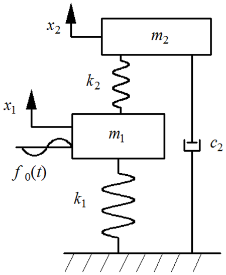
Grounded type DVA.
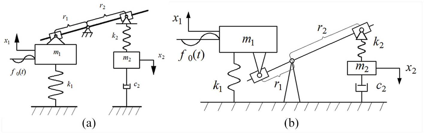
(a) Grounded type DVA with lever component as lever fulcrum fixed at another inertial reference frame and (b) Grounded type DVA with lever component as lever fulcrum fixed at ground.
Defining the amplification ratio of the lever as

Using the following parametric transformation

Equation (1) becomes

Supposing the solution as

where

Accordingly
The frequency response functions of the primary system and absorber system are

H∞ optimization criterion
In the following part, Model 2 will be optimized based on H∞ criterion by using the fixed-point theory. 5 For the convenience of derivation, one can introduce the following parameters

The amplitude amplification factor A of the primary system can be written as

where

According to the fixed-point theory, the amplitude-frequency response curves of the primary system have two fixed points (P and Q), which are independent of the damping ratio, as shown in Figure 3.
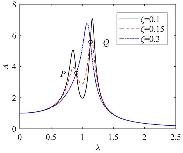
The amplitude-frequency response curves of the primary system for three different damping ratios with the parameters μ = 0.1, ν = 1, L = 1.
In equation (7), A is independent of
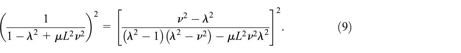
According to this condition, the abscissas at P and Q points can be obtained by derivation. When removing the square and adding a positive sign to the side of the equation (9), one could obtain

One can obtain the abscissa values of P and Q by solving equation (10)

If

Because the amplitudes at the fixed point are independent of the damping, one can get the amplitude at the fixed point by substituting equation (11) into equation (12). It should be noted that P and Q point are in opposite phase. In order to make the amplitude of the Q point positive, a minus sign should be added to Q point.


Because the peaks of the amplitude-frequency response curve can be located near the fixed points by adjusting the damping ratio, the amplitude of the fixed point determines the minimum value of the maximum amplitude of the primary system. If the mass ratio and amplification ratio are constant, the relation between the amplitudes of the two fixed points and the frequency ratio can be obtained by equation (13a) and (13b), as shown in Figure 4. In the classical fixed-point theory, the optimum frequency ratio is obtained by adjusting the two fixed points to the same height, and then the optimum damping ratio is obtained by adjusting the fixed points to the peak value. However, it can be seen that the point M in Figure 4 is only local minimum when the two fixed points are at the same height. The maximum amplitude of primary system can be smaller if the frequency ratio is greater than point N. Thus the abscissa of point M is the local optimum frequency ratio, and one can obtain the local optimum frequency ratio by equalizing equations (13a) and (13b).


The relation between the amplitude of the two fixed points and the frequency ratio with the parameters L2μ = 0.1.
The local maximum amplitude can be obtained by substituting equation (14) into equation (13a) or equation (13b)
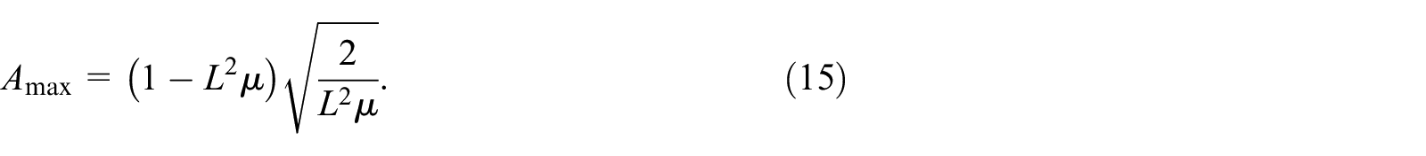
According to equations (13a) and (15) one can obtain the abscissa of point N
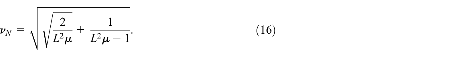
With the increase of the mass ratio and amplification ratio, the intersection of P and Q on the curve will move. It can be seen from Figure 5 that there is no local optimum parameter if the intersection M located at the peak position of the P curve. According to equations (14) and (16) one can obtain the system parameters

The relation between the amplitude of the two fixed points and the frequency ratio with the parameters L2μ = 0.268.
By subtracting (13a) from (13b) one can find

Equation (17) is always negative if
According to the above discussion, the following results can be obtained: (1) When
In order to make P and Q at the highest point of the curve, the derivative value of P and Q should be 0. Squaring A and

Next the procedure will be given to obtain the optimum damping ratio. For the convenient of derivation one can use

Accordingly

Namely

where

If
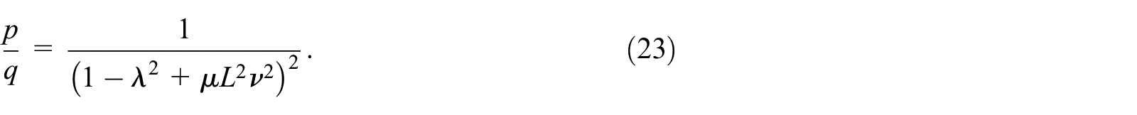
According to equations (18) and (21) one can obtain

The damping ratios that make P or Q at highest point can obtain by substituting equations (13a) and (13b) into equation (24), respectively


By substituting equation (14) into equation (11), the abscissas that let the two fixed points at the same height can be obtained

By substituting equation (26) into equation (24), one can obtain the damping ratio that makes P and Q at the same height that is, local optimum damping ratio

So far, the local optimum damping ratio and the damping ratios that make P and Q at the highest points have been obtained. Table 1 shows the optimum parameters corresponding to the system parameters in different ranges. Although the local optimum parameters will not minimize the response of the primary system in the whole range, its can always keep the two fixed points at the peak position and its expression is simpler. Therefore, the local optimum parameters are still selected to analyze Model 2 in the next part.
The optimum parameters corresponding to the system parameters in different ranges.

H2 optimization criterion
The purpose of H2 optimization is to minimize the mean square displacement of the primary system when it is subjected to random force excitation. The performance index to be optimized is defined as

where I represents the ratio of the response of the primary system to the force excitation with an uniform power spectral density Sf. Constant
The mean square displacement of the primary system is

where

The performance index can be written as

Then I can be solved by using the method in the literature 50

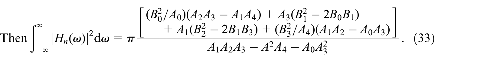
Equation (31) can be written as

Differentiating equation (34) and making its result zero can minimize I
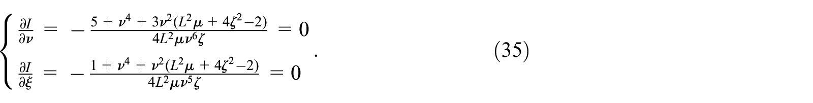
Solving equation (35) can get the optimum parameters for H2 optimization


The optimum parameters and performance of Model 1 based on H2 optimization have been studied in literature.
10
The results show that Model 1 does not have the global minimum mean square displacement. It only has the local minimum mean square displacement and local optimum frequency ratio if
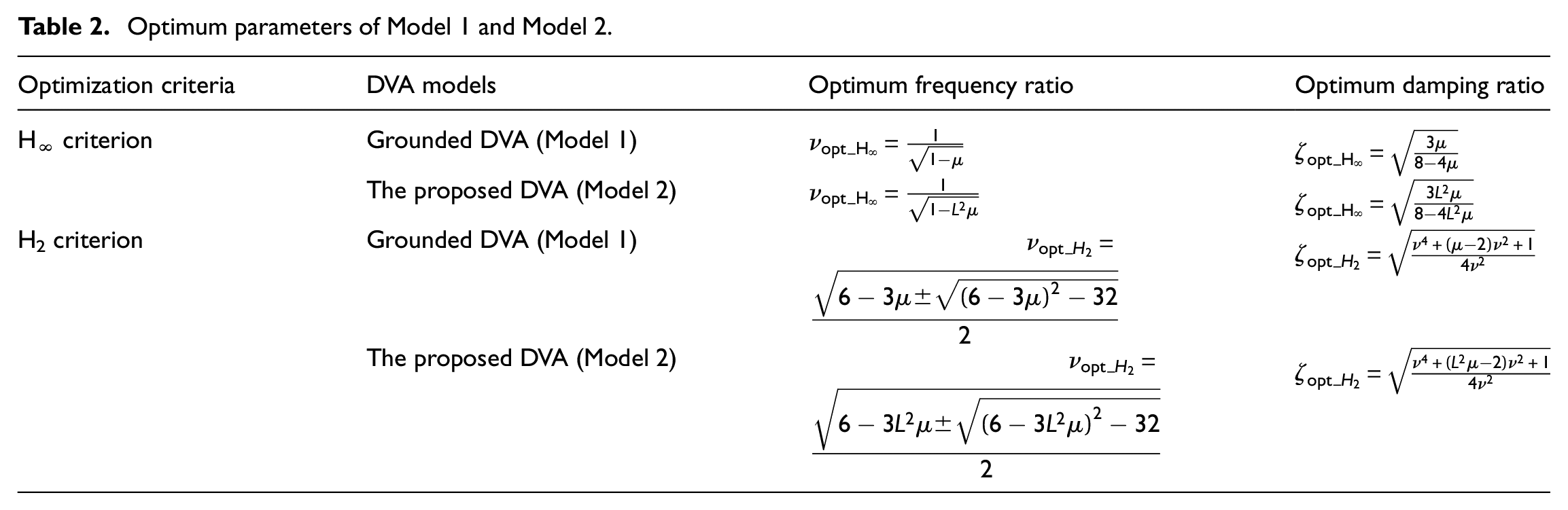
The main change in Model 2 is the introduction of lever into Model 1. One can find that the mean square displacement and optimum parameters of Model 2 are the same as those of model 1 except that

Optimum parameters of Model 1 and Model 2.
The performance indexes of different types of DVAs.

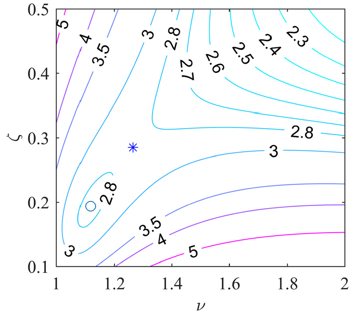
The contours of the mean square displacement of the primary system as L2μ = 0.1.
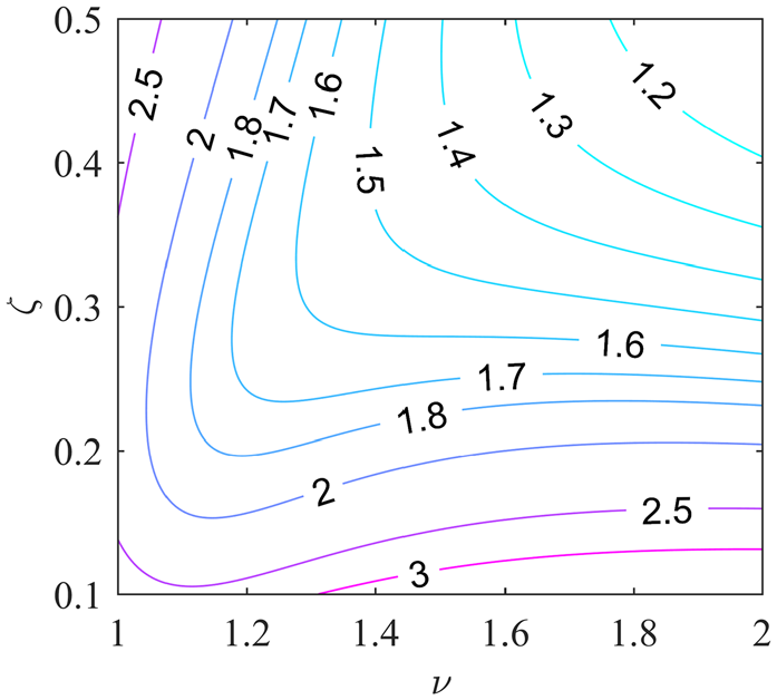
The contours of the mean square displacement of the primary system as L2μ = 0.2.
According to Table 1 and equations (36) and (37), the amplitude-frequency response curves with optimum parameters in H∞ and H2 criteria can be obtained and shown in Figures 8 and 9. The solid line in the two figures corresponds to analytical solution, which is obtained by substituting the optimum parameters into equation (7). The circles denote numerical solution, which is obtained through the numerically integrating for equation (2) by using the 4th-order Runge-Kutta method. It can be seen that the numerical solution is precisely coincide with the analytical solution, which proves the correctness of the analytical results.
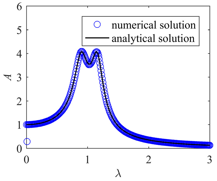
The amplitude-frequency response curves of the primary system by numerical solution and analytical solution with the H∞ parameters μ = 0.1, L = 1, νopt_H∞ = 1.0541, ςopt_H∞ = 0.1987.

The amplitude-frequency response curves of the primary system by numerical solution and analytical solution with the H2 parameters μ = 0.1, L = 1, ν = 1.5, ςopt_H2 = 0.4457.
The effect of lever on the DVA performance
If the amplification ratio is

The amplitude-frequency response curve of primary system for different amplification ratios with the system parameter μ = 0.1 and the parameters in H∞ optimization.

The amplitude-frequency response curve of primary system for different amplification ratios with the system parameter μ = 0.1, ν = 1.5 and the parameters in H2 optimization.
It can also be seen from Figures 10 and 11 that the performance of the DVA is improved in the medium frequency range (0.5–1.5 times the natural frequency of the primary system, that is,
The reason for the performance decline of the DVA in the high frequency range is that the natural frequency of the system has changed after using the lever. The natural frequency expression in dimensionless form can be obtained after solving equation (7)

Figure 12 shows the relation between the natural frequency in dimensionless form and the amplification ratio. It can be seen from the figure that as the amplification ratio increases, one of the two natural frequencies increases and the other decreases. The shift for the natural frequency to the high frequency range causes the performance of the DVA to decline slightly in the high frequency range.

The relation between natural frequency in dimensionless form and amplification ratio as μ = 0.1.
Although the performance of the DVA with lever is slightly decline in the high frequency range, its performance in the medium frequency range has been improved obviously. On the whole, the use of lever is beneficial to the DVA’s performance, because the DVA with lever can greatly reduce the amplitude of the system in the resonance region.
Performance comparison with typical DVAs
In order to investigate and verify the control performance of Model 2, the control performance of Model 2 and other three typical DVAs, that is, the Voigt DVA by Den Hartog, grounded type DVA (i.e. Model 1) by Ren and three-element type DVA by Asami and Nishihara, are compared under H∞ and H2 criteria.5,7,13 According to the results in Section 2 and Section 3, large amplification ratio and frequency ratio will make the amplitude and the area under the curve smaller. However, large amplification ratio also increases the size of the DVA. Considering the installation space of the DVA, the amplification ratio will be selected as 2, and the frequency ratio will be selected as 1.5 in Model 1 and Model 2 in the next investigation.
Performance comparison under H∞ and H2 criteria
The optimum parameters, performance index and amplitude amplification factor of other DVAs can be obtained from the literatures, respectively.5,7,10,13,14 The amplitude-frequency response curves of several DVAs under the H∞ and H2 criteria are shown in Figures 13 and 14. The performance indexes of each DVA under H∞ and H2 are summarized in Table 3. The relationship between their performance index and mass ratio is also given here, as shown in Figures 15 and 16. It can be seen from Figures 13 and 14 that the amplitude and the area under the curve of the proposed DVA (Model 2) are much smaller than other DVAs. Figures 15 and 16 also prove that the performance of the proposed DVA is better than other DVA under H∞ and H2 criterion.
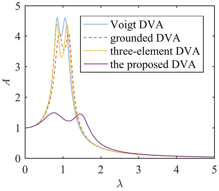
The amplitude-frequency response curves of primary system for different DVA systems with the mass ratio μ = 0.1 and the parameters in H∞ optimization.
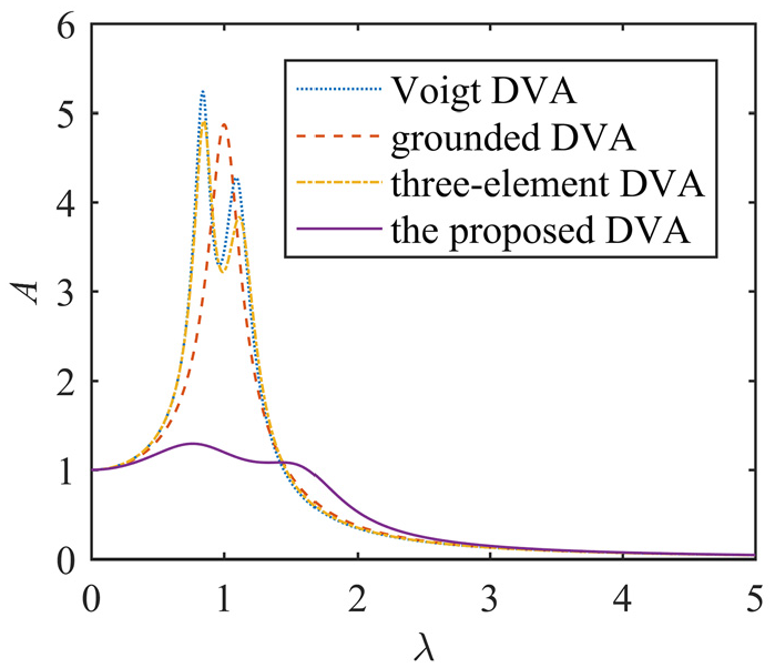
The amplitude-frequency response curves of primary system for different DVA systems with the mass ratio μ = 0.1 and the parameters in H2 optimization.

Performance index of several different DVAs under H∞ criterion.

Performance index of several different DVAs under H2 criterion.
Time history of displacement response of primary system
In order to get more realistic results, a 500s random force excitation is constructed, which is composed of 5000 normalized random numbers with zero mean value and unit variance. The time history of the random force excitation and its power spectrum density function (PSD) are respectively shown in Figures 17 and 18. Under the same system parameters

Random force excitation.
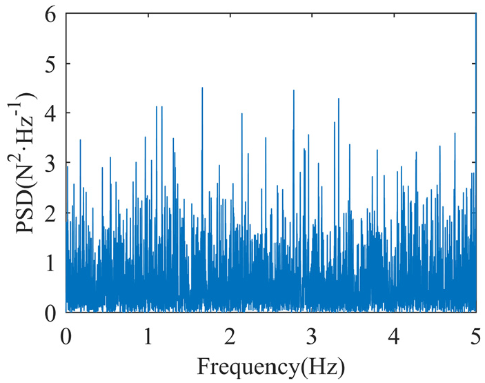
The power spectrum density function corresponding to random force excitation in Figure 17.

Time history of displacement responses of the primary system for without DVA and with the proposed DVA under random force excitation.

Time history of displacement responses of the primary system for with Voigt DVA and the proposed DVA under random force excitation.

Time history of displacement responses of the primary system for with grounded DVA and the proposed DVA under random force excitation.

Time history of displacement responses of the primary system for with three-element DVA and the proposed DVA under random force excitation.
The displacement standard deviation of the primary system is often related to the fluctuation of the vibration energy of the system. One can obtain the standard deviations by calculating the variance of displacement in Figures 19 to 22. The displacement standard deviations and decrease ratios of the primary system for the different DVAs are summarized in Table 4. It can be seen that the standard deviations value of the proposed DVA is smallest. The above investigations demonstrate that the DVA proposed in this paper has excellent control performance.
The standard deviations and decrease ratios of the displacement of the primary system.

Conclusion
A new grounded type DVA with lever component is studied. The DVA is optimized base on H∞ and H2 criterion. The optimization results show that there are no global optimum parameters, and larger frequency ratio will get better control performance. The optimum parameters are summarized in Tables 1 and 2. The effect of the lever on the performance of the proposed DVA is analyzed. Based on the lever principle, the inertial and spring forces acting on the primary system will be amplified or reduced. According to the values of the amplification ratio, it is divided into three cases, that is, the amplitude of the primary system will be reduced, amplified or unchanged when the amplification ratio is greater than 1, less than 1 or equal to 1, respectively. The use of the lever can increase the effective mass of the DVA. There is no optimum value for the amplification ratio, and it has the same effect as the mass ratio. Theoretically speaking, the larger the amplification ratio is, the better response control performance will be. After studying the performance of the proposed DVA and comparing it with other typical DVAs, the results demonstrate that the DVA proposed in this paper can present better control performance and smaller mass by increasing the amplification ratio. The new results of this study provide a solution to solve the problem that the performance of DVA is limited by mass ratio. Further study will focus on using other forms of amplification mechanisms to reduce size of the DVA.
Footnotes
Declaration of conflicting interests
The author(s) declared no potential conflicts of interest with respect to the research, authorship, and/or publication of this article.
Funding
The author(s) disclosed receipt of the following financial support for the research, authorship, and/or publication of this article: The authors are grateful to the support by National Natural Science Foundation of China (No. U1934201, 11772206 and 11672191), the State Scholarship Fund from the China Scholarship Council (CSC), the Cultivation plan for Innovation team and leading talent in Colleges and Universities of Hebei Province (LJRC018), the Program for advanced talent in the universities of Hebei Province (GCC2014053).