
Abstract
In order to study the characteristics of a rolling lobe air spring, a vertical stiffness analytical model is constructed based on thermodynamics and hydrodynamics. The merit of this vertical stiffness analytical model is that an analytical solution of geometric parameters is obtained by an approximate analytic method. Meanwhile, experimental tests are carried out to verify the accuracy of the vertical stiffness analytical model. The vertical stiffness analytical model can be used to qualitatively analyze the influence of geometric parameters on the vertical stiffness characteristics of a rolling lobe air spring. Therefore, the relationship between geometric parameters and the vertical stiffness characteristics is analyzed based on the proposed model. The conclusions show that the vertical stiffness analytical model can well predict the mechanical characteristics of a rolling lobe air spring and provide guidance for parameter design and vehicle ride comfort improvement.
Keywords
Introduction
Rolling lobe air springs have significant advantages, attenuating the harmful vibrations and improving the vehicle’s safety and ride comfort. The rolling lobe air spring as a critical component for the secondary suspension system has been widely used in mainline railway vehicles, high-speed trains, and commercial vehicles. 1 The rolling lobe air spring is located between the car body and bogie frame, and its structure is simple, as shown in Figure 1. It consists of a top plate, a rubber diaphragm, an emergency spring, and a bottom plate. The vertical stiffness and damping characteristics of a rolling lobe air spring exhibit strong nonlinearity. Therefore, establishing an accurate model is the key to study its stiffness and damping characteristics and a vehicle’s mechanical properties.

Structure of a rolling lobe air spring system.
In recent decades, extensive research has been done by many scholars on the air spring stiffness modeling and vehicle dynamics analysis. Quaglia and Sorli 2 and Quaglia and Guala 3 proposed a dimensionless linear model for pneumatic suspension using hydrodynamics, and some design considerations were offered to analyze the effect of parameters on the stiffness characteristics. Liu and Lee 4 derived a theoretical model to investigate the dynamic stiffness and overall equivalent damping of an air spring using energy conservation and gas state equations. Docquier et al. 5 presented a multidisciplinary modeling approach for the bellow–pipe–tank subsystem of railway pneumatic suspension. Nakajima et al. 6 developed a nonlinear model of the air spring system based on thermodynamics, and the coupling effect of the leveling valves and differential pressure valves was considered. Zhu et al.7,8 developed an air spring vertical dynamic model to predict the dynamic characteristics of air springs, in which the thermodynamics of the bellow–pipe–tank pneumatic subsystem, effective friction, and viscoelastic damping of bellow rubber were taken into account. Facchinetti et al. 9 developed two different modeling approaches for air spring suspension, a quasi-static one based upon mechanics analysis and a dynamic one based on thermodynamics. Wang and Zhu 10 derived a dynamic stiffness model of an air spring based on hydrodynamics and thermodynamics. Li and Li 11 and Li et al. 12 deduced an analytical solution to express the vertical stiffness of air springs, and the influence of geometric parameters on vertical stiffness was analyzed in terms of this analytical solution. Chen et al. 13 refined a new bellow model to describe the vertical stiffness of a convoluted air spring, and the structural parameters are processed using a geometrical analysis approach. Wenku et al. 14 built a finite element model (FEM) of an air spring to study its static elastic characteristics, and the impact of geometric parameters on the elastic characteristics was studied using a sensitivity analysis. Alonso et al. 15 constructed a test bench to describe the characteristics of the air spring system, and the relationship between the geometric parameters and ride comfort was explored. Moheyeldein et al. 16 proposed a new dynamical model incorporating the damping characteristics of an air spring to study the performance of the air spring. Mazzola and Berg 17 defined an accurate component model of an air spring based on a combination of laboratory tests and model identification techniques. Jingyue et al. 18 obtained a nonlinear air spring polynomial model based on the polynomial and radial basis curve fitting method.
These studies showed that there are mature research results on the vertical stiffness modeling for air springs, but studies on the vertical stiffness modeling of rolling lobe air springs are less. Furthermore, the geometric parameters were available from manufactures and experimental tests, which is unacceptable for the qualitative analysis of air spring stiffness characteristics. Therefore, a novel vertical stiffness analytical model of a rolling lobe air spring is constructed based on thermodynamics and hydrodynamics in this article, and its geometric parameters such as the effective area, the equivalent volume, and their derivative terms are deduced using an approximate analytical method.
The layout of this article is as follows. First, the motion model of a rolling lobe air spring is analyzed, and a vertical stiffness analytical model is established based on the thermodynamic theory, hydrodynamic theory, and approximate analytical method. Second, experimental tests are carried out to verify the proposed vertical stiffness analytical model. Third, the impact of geometric parameters on vertical stiffness is analyzed using a sensitivity analysis approach, and also the influence of geometric parameters on vehicle ride comfort is evaluated using the Sperling comfort index. Finally, the conclusion is presented showing that the vertical stiffness analytical model can accurately predict the mechanical characteristics of a rolling lobe air spring, and a guideline for the design of these springs and an improvement in vehicle ride comfort is obtained.
Modeling development
From the perspective of control strategy design, the rolling lobe air spring is simplified as a variable stiffness spring and a damper, and its single-degree-of-freedom vertical motion model is shown in Figure 2.

Single-degree-of-freedom model of a rolling lobe air spring.
According to Figure 2, the motion equation of the rolling lobe air spring can be expressed as

where
In order to precisely reproduce the stiffness and damping characteristics of the rolling lobe air spring, a vertical stiffness analytical model is deduced based on thermodynamics and hydrodynamics, and its geometric parameters are obtained through an approximate analytical method.
Vertical stiffness modeling
The rolling lobe air spring is different from the typical bellow–pipe–tank pneumatic system, and its auxiliary chamber is linked to the rubber diaphragm via an orifice. Referring to the literature,2,8 the vertical stiffness model is established on the basis of hydrodynamics and thermodynamics.
The resilience of the air spring

where
The gas in the rubber diaphragm can be assumed as an ideal gas, and thus it satisfies the laws of thermodynamics, which can be expressed as follows


where
According to equation (4), the differential equation of the pressure in the rubber diaphragm

The mass flow rate

where
Differentiating equation (2) and then substituting equation (5) into it, the vertical stiffness of the rolling lobe air spring can be obtained as follows

where
From equation (7), the vertical stiffness
Analytical modeling
As mentioned above, the geometric parameters play a key role in the vertical stiffness of the rolling lobe air spring. In order to qualitatively analyze the relationship between the vertical stiffness characteristics and geometric parameters, an approximate analysis method is used to process the geometric parameters.
Under a small vertical deflection, the rubber diaphragm changes from the initial position (black solid line) to the current state (red solid line). The simplified diagram of the vertical deformation of a rolling lobe air spring is shown in Figure 3.12,13
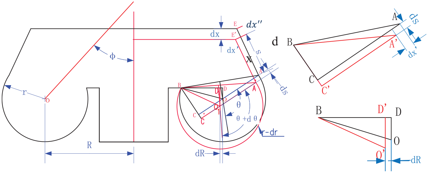
Schematic diagram of the vertical deformation of a rolling lobe air spring.
The symbols in Figure 3 are defined as follows: dR, S, ds, dx′, and dx″ are intermediate variables,
According to Figure 3 and the assumptions, the geometric variable equations can be obtained by comparing the arc length before and after deflection


where ds can be derived by calculating the lengths of BC and BC′ in the triangles ABC and A′BC′, as follows


Combining equations (9) and (11), we obtain

Comparing the lengths of AC and AC′ in the triangles ABC and A′BC′, dx′ can be derived as follows

From the deformation in Figure 3, the following relationship can be obtained


Substituting equations (13)–(15) into equation (12), the following equations can be derived


where

Substituting equations (16) and (17) into equation (18),

The effective area

The effective area after deflection can be expressed as follows

Combining equations (19) and (21), the rate of change of the effective area can be derived as

where

Under a small vertical displacement excitation, the change rate of the rubber diaphragm volume can be simply expressed as follows

Substituting equations (22) and (23) into equation (7) yields the analytical formula for the vertical stiffness of the rolling lobe air spring

where

Experiments and simulation
The rolling lobe air springs studied in this article were designed and manufactured by the CRRC Zhuzhou Locomotive Company, and performance experiments were also performed at this company. In this section, the simulation results were compared with the experimental data to validate the accuracy of the proposed vertical stiffness analytical model.
Experimental data
The structure and working principle of the experimental setup have been described in detail by Li et al. 12 and Li and Qi, 1 as shown in Figure 4. A load sensor was mounted in the upper part of the setup to measure the vertical force. A vibration platform was positioned at the bottom of the setup to simulate the track excitation, and the auxiliary chamber was connected to the air spring through a pipe. The working range of the displacement sensor is 75 mm, the axial sensitivity is 500 ± 5% mV/g, and the response frequency is 0.3–2500 Hz. The geometric parameters of a rolling lobe air spring used in the setup are listed in Table 1.
Geometric parameters of a rolling lobe air spring.


Schematic diagram of the experimental setup.
According to the TB/T 2841-2010 air spring for railway vehicles, 19 the vertical preload is 50–125 kN, representing the empty load case AW0 and the overload case AW3. The vertical excitation displacement was simulated using a set of sinusoidal waves with different amplitudes and frequencies. Table 2 summarizes the main parameters of the vertical excitation.
Excitation parameters.

The experimental tests were conducted under a harmonic displacement excitation with a frequency range of 0–20 Hz and an amplitude range of 2–10 mm. The experimental data are plotted in Figure 5. It can be seen that the vertical stiffness mainly depends on the excitation amplitude and decreases with the increase in the excitation amplitude. The vertical stiffness has a little relationship with the excitation frequency.

Experimental data: (a) the AW0 case and (b) the AW3 case.
Simulation and validation
Figure 6 shows the simulation results of the vertical stiffness analytical model, where the vertical stiffness increases with the increase in pressure. Comparing the simulation results of Figure 6(a) and (b), it can be seen that the vertical stiffness displays a significant reduction of about 61% with the increase in the auxiliary chamber volume.
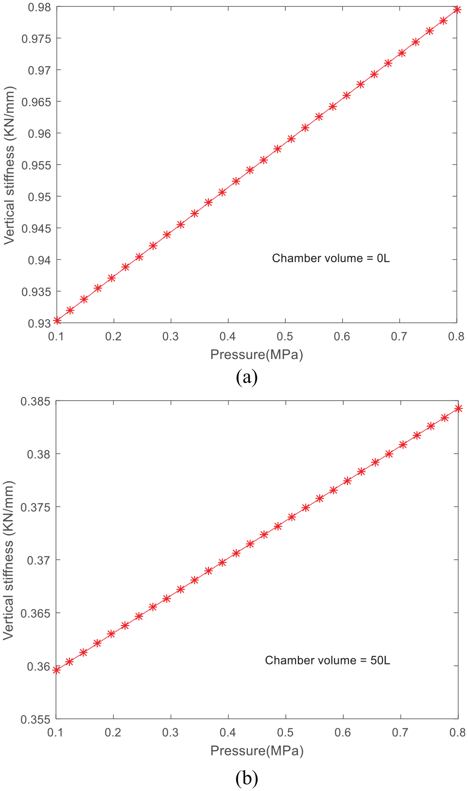
Simulation results: (a) V2 = 0 L and (b) V2 = 50 L.
Figure 7 shows the comparison of the experimental data and simulation results. It is clear that the simulation results of the proposed vertical stiffness analytical model and the experimental data show the same trend. When the auxiliary chamber volume

Comparison results: (a) V2 = 0 L and (b) V2 = 50 L.
When the auxiliary chamber volume
Analysis and discussion
In this section, the impact of the geometric parameters on the vertical stiffness characteristics of the rolling lobe air spring is qualitatively analyzed by a sensitivity analysis method.
Impact of the rubber diaphragm volume
Figure 8 shows the influence of the rubber diaphragm volume on the vertical stiffness. In the case of the auxiliary chamber volume of 0 L, the vertical stiffness decreases dramatically as the diaphragm volume increases. When the diaphragm volume exceeds 30 L, the vertical stiffness reaches a small value and changes slightly, as shown in Figure 8(a). When the auxiliary chamber volume is 50 L, as shown in Figure 8(b), the recession curve of vertical stiffness tends to be smooth as the chamber volume increases. The reason for this behavior is that the damping force generated by the air flow through the orifice effectively alleviates the attenuation of the vertical stiffness. The simulation results show that the optimal rubber diaphragm volume of a rolling lobe air spring is within a range of 20–40 L.
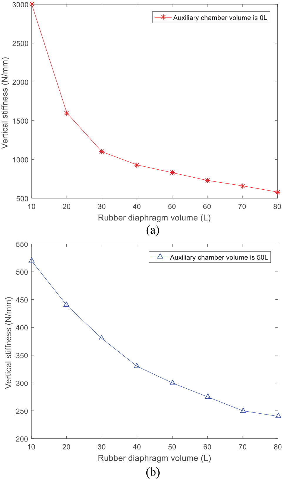
Vertical stiffness versus rubber diaphragm volume: (a) V2 = 0 L and (b) V2 = 50 L.
Impact of the auxiliary chamber volume
One of the principal influences on the vertical stiffness of an air spring is the auxiliary chamber volume. It can be seen from Figure 9 that the vertical stiffness decreases with the increase in the auxiliary chamber volume. According to the discussion in Figure 8, better stiffness and damping performance can be obtained by designing an appropriate volume ratio of the auxiliary chamber and the rubber diaphragm, which can be derived from the following formula


Vertical stiffness versus auxiliary chamber volume.
Impact of the shape coefficient
The shape coefficient

Synergistic relationship of constrain angle and diaphragm angle versus shape coefficient (a), shape coefficient versus diaphragm angle (b), shape coefficient versus constrain angle(c).
Figure 11 shows the relationship between the vertical stiffness and the shape coefficient
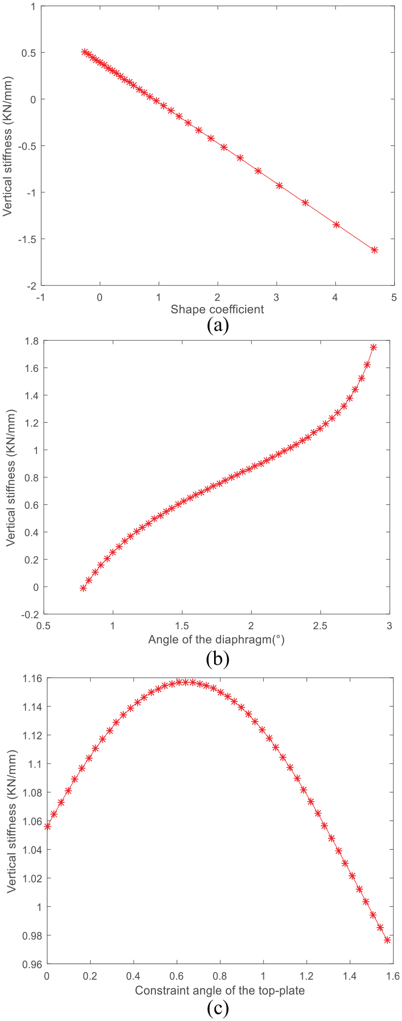
Vertical stiffness versus shape coefficient (a), vertical stiffness versus diaphragm angle (b), vertical stiffness versus constrain angle(c)
From Figure 11(b), it can be seen that the vertical stiffness increases as the angle
Ride comfort analysis
A set of optimal solutions of geometric parameters can be obtained through the vertical stiffness analytical model, and the influence of the geometric parameters on the vertical stiffness characteristics can be quantitatively evaluated by the vehicle comfort index. In this section, the Sperling comfort index is used to assess the influence of the geometric parameters before and after optimization on the vertical stiffness behaviors.
Sperling comfort index
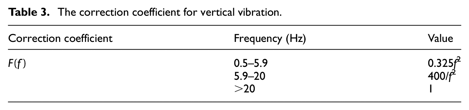
The Sperling comfort index is widely used as an international standard to evaluate the ride comfort of vehicles, 20 which is expressed as
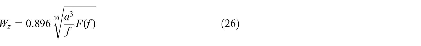
where
The correction coefficient for vertical vibration.
According to the Sperling standard, the ride comfort index is divided into four grades, as shown in Table 4.
Ride comfort classification.

Vibration acceleration
According to the motion equation (1) and vertical stiffness formula (7), the vertical resilience of a rolling lobe air spring

Combining equations (24) and (27), the vibration acceleration of the car body

Through the above analysis and discussion, the geometric parameters with optimization and no optimization are listed in Table 5.
Input geometric parameters.

Substituting the data in Table 5 into equation (28), the magnitude of the car-body acceleration is shown in Figure 12. The simulation results show that the acceleration amplitude obtained in the case of the optimized parameters is obviously smaller than that in the case of nonoptimized ones, and also the ride comfort index is smaller than that in the case of nonoptimized ones, as shown in Figure 12(b).

Simulation results of car-body accelerations (a) and ride comfort index (b).
Conclusion
In this article, a vertical stiffness analytical model of a rolling lobe air spring is constructed based on hydrodynamics and thermodynamics. The main advance of the vertical stiffness analytical model is that the geometric parameters are processed with an approximate analytical method. The proposed vertical stiffness analytical model is verified by comparing with the experimental data of the rolling lobe air spring. Meanwhile, the influence of the rubber diaphragm volume, auxiliary chamber volume, and shape coefficient on the vertical stiffness characteristics is analyzed and discussed, and also the impact of the geometric parameters on the vertical stiffness characteristics is evaluated by the Sperling comfort index; some valuable conclusions are drawn as follows:
The mechanical characteristics of a rolling lobe air spring can be well characterized using the vertical stiffness analytical model.
The geometric parameters of a rolling lobe air spring can be deduced using an approximate analysis method.
An appropriate volume ratio of the auxiliary chamber and the rubber diaphragm can be derived from equation (25).
A quick estimate of the shape coefficient of a rolling lobe air spring can be obtained based on the vertical stiffness analytical model, and the reasonable ranges for the angle of diaphragm
A set of optimized geometric parameters can be obtained using the sensitivity analysis approach.
In summary, the proposed vertical stiffness analytical model can accurately predict the mechanical characteristics of a rolling lobe air spring. Some conclusions are obtained to provide guidance for parameter design and vehicle ride comfort improvement.
Footnotes
Declaration of conflicting interests
The author(s) declared no potential conflicts of interest with respect to the research, authorship, and/or publication of this article.
Funding
The author(s) received no financial support for the research, authorship, and/or publication of this article.