
Abstract
Due to the enormous energy densities of liquid hydrocarbon fuels for future utilization on micro scale, there is a concern about the feasibility of scaling down reciprocating internal combustion engines from small scale to meso scale. By building a specialized test bench, the performance and combustion characteristics of a miniature internal combustion engine with a displacement of 0.99 cc were tested, and the thermodynamic simulation was carried out to achieve a more complete understanding of in-cylinder mass and energy change of the miniature internal combustion engine. The miniature internal combustion engine had higher brake-specific fuel consumption, lower thermal efficiency, lower brake mean effective pressure, and serious cyclic variation; however, friction mean effective pressure seems to be less sensitive to engine speed. Simulation results showed that the miniature internal combustion engine had a poor volumetric efficiency, which was not more than 50%. The step-by-step processes of scaling down the miniature internal combustion engine were also simulated; it was found that the maximum indicated mean effective pressure loss was due to the imperfection of gas exchange processes, and the next was the imperfection of combustion. It is considered that for the scaled-down miniature internal combustion engines, more attention should be pay on improving the processes of gas exchange and combustion, and achieving meso-scale internal combustion engines with cylinder bore less than 1 mm is thermodynamically possible in future if these imperfections, especially that of the gas exchange process, can be effectively perfected.
Keywords
Introduction
High energy density power systems are urgently needed for human portable devices to realize more size reduction and longer running time.1–3 Since the specific energy of hydrocarbon fuels are much greater than that of traditional chemical batteries, the miniature heat engines that use hydrocarbon fuels appear to be a natural choice for high energy density power units.4–6 Up to now, a series of micro engine programs, such as micro gas turbine engine, micro internal combustion engine, Micro-Electro-Mechanical System (MEMS) rotary engine, and MEMS free piston engine, have been developed.7–12 However, scaled-down reciprocating internal combustion (IC) engines should be attracting more attention.13–16
To enable the development of scaling laws for small engine performance, Menon et al. 17 constructed a dynamometer system suitable for measuring the performance of small IC engines and presented detailed performance measurements for a particular engine with a mass of 150 g. Rowton et al. 18 analyzed and created scaling relationships for performance and efficiency among the scaling study IC engines, deduced that when the ratio of cylinder surface area to swept volume is less than 1.5 cm−1, the cylinder wall heat loss is the main mechanism of thermal efficiency loss, and the performance of the scaled-down IC engine will be significantly affected. Sher and colleagues19,20 developed a phenomenological model to consider the relevant processes inside the cylinder of a homogeneous-charge compression-ignition (HCCI) engine, proposed an approximated analytical solution to yield the lower possible limits of scaling down HCCI cycle engines, and indicated the minimum allowed engine size is between 0.3 and 0.4 cc (bore diameter ∼7.5 mm) and the maximum obstacle of scaling down the engines is gas leakage of blow-by. Menon and Cadou21,22 studied the scaling rules which were derived from comprehensive dynamometer investigations of nine of the smallest commercially available miniature IC engines, indicated that the minimum length scale of a thermodynamically viable IC engine is approximately 5 mm and the maximum energy loss is incomplete combustion. However, the conclusions of these existing studies are not completely consistent with the actual situation in some way. Nowadays, the Ronald Valentine Engines has commercially developed a miniature IC engine with a cylinder diameter of 3 mm. 23 So it is urgent to known whether or not the IC engines can be further scaled down.
In the present work, a miniature reciprocating IC engine with displacement of 0.99 cc was experimentally investigated; correspondingly, a thermodynamic numerical model was constructed. By assembling the test data of combustion diagnosis which has never been performed on such a small IC engine into the thermodynamic model, a thermodynamic simulation was carried out to achieve a more complete understanding of in-cylinder mass and energy change of the miniature IC engine, and give the reasons for the low brake mean effective pressure (BMEP) and the poor thermal efficiency. Then the step-by-step process of scaling down the miniature IC engine was simulated, and the factors contributing to the indicated mean effective pressure (IMEP) loss of the scaled-down miniature IC engines were figured out. It is found that for the scaled-down miniature IC engines, most of the IMEP loss is due to the imperfection of gas exchange process, the second is due to the imperfection of combustion, and the third is due to the mass leakage of blow-by; the effect of heat transfer on the IMEP loss is comparatively smaller. Therefore, if these imperfections, especially that of the gas exchange process, can be effectively perfected, achieving meso-scale IC engines with cylinder bore less than 1 mm is thermodynamically possible.
Performance test and combustion diagnosis
A specialized miniature IC engine test bench was constructed as shown in Figure 1, which consists of a high-speed motor, an air-cooled absorber, and a test miniature IC engine. The test bench is driven by the motor, and a frequency converter is used to adjust the motor speed. The power output and the friction loss of the miniature IC engine are obtained by measuring the brake torque change of a hysteresis type brake (AHB-202A), whose brake torque is directly proportional to a supplied current. A cooling duct directs air from a small air compressor into the hysteresis brake. The current to the hysteresis brake is controlled by a DC regulated power supply and measured by an ampere meter. Fuel flow rate is calculated by timing the fuel weight changing in the fuel tank and air flow rate is tested by a vane flow-meter that has an operating range of 100-1200 L/h. A K-type thermocouple and an optical revolution counter are, respectively, used for the measurement of the cylinder head temperature and the engine speed.

The constructed performance test bench of the miniature IC engine.
The test miniature IC engine is a two-stroke, single-cylinder, glow-ignition, no piston ring, and air-cooled reciprocating engine with following dimensions: bore 11.25 mm, stroke 10 mm, and geometric compression ratio 8. It is fueled with a mixture of 67% methanol, 15% nitromethane, and 18% castor oil. Figure 2 shows the test results of the miniature IC engine at full load. The maximum power output of the miniature IC engine is approximately 70 W, while the maximum friction power exceeds 40 W, and the fuel flow rate reaches to 300 g/h near the highest operating speed (around 18,000 r/min). The data also show that cylinder head temperature is approximately at 160°C to 200°C, indicating a minor heat load.

Performance of the miniature IC engine tested at the test bench: (a) output power and friction power; (b) fuel consumption and temperature of cylinder head. Notation: 1—output power; 2—friction power; 3—fuel consumption; 4—temperature of cylinder head.
The in-cylinder combustion pressure of the miniature IC engine was measured by a piezoelectric transducer (Kistler Type 6052B) and a charge amplifier (Kistler Type 5011B), and crankshaft angle was measured by an optic encoder (Kistler Type 2613B). Signals of pressure transducer and encoder were sent into the data acquisition system of DEWE-2010. To install the piezoelectric transducer, the cylinder head of the miniature IC engine was modified. 14 It is verified that the test miniature IC engine with modified cylinder head has almost the same power output as the original unmodified engine.
Figure 3 shows the IMEP and the peak pressure (pmax) of continuously sampled 120 test cycles at the engine speed of 6000 r/min. It can be seen that the miniature IC engine has serious cyclic variation. The coefficients of variation (COV), that is, standard deviation/mean, are around 22% for IMEP, and around 28% for pmax. As seen in Figure 3(a), IMEP of the miniature IC engine is very low (mean value about 280 kPa), and for some test cycles, IMEP is even less than 50% of the overall average IMEP, which indicates poor combustion occurring inside the test engine. In Figure 3(b), it should be noted that the peak pressure of several cycles is even equal to that under motoring condition, which is proved to be relevant to misfire or partial burning by the heat release analysis of combustion diagnosis.

Cyclic variation of IMEP and peak pressure over continuously sampled 120 cycles at 6000 r/min: (a) cyclic variation in IMEP; (b) cyclic variation in peak pressure.
Figure 4(a) shows the severe variation of crank angle at which fuel mass fraction of 5% (CA05) is burned, which usually represents start of combustion. It is deduced that the glow ignition of the miniature IC engine cannot give stable ignition timing, and thus the start of combustion varies considerably from cycle to cycle, bringing about the serious cycle-by-cycle variation of the miniature IC engine. Figure 4(b) shows variation of combustion duration, which also indicates serious cycle-by-cycle variation. Furthermore, the combustion duration of the miniature IC engine seems longer than that of conventional size gasoline engines which is generally about 30°CA, indicating much slower heat release rate.

Cyclic variation of heat release rate over continuously sampled 120 cycles at 6000 r/min: (a) cyclic variation in IMEP; (b) cyclic variation in peak pressure.
Performance analysis and discussion
The performance of the miniature IC engine was compared with that of four types of conventional size IC engines, that is, a 5.9-L six-cylinder diesel engine, a 2.0-L four-cylinder gasoline engine, a 0.15-L single-cylinder gasoline engine, and a 0.1-L single-cylinder gasoline engine. Table 1 gives the specifications of these conventional size IC engines and their performances are shown in Figure 5. As shown in Figure 6, the specific characteristic parameters at full load including the BMEP, the specific power (the ratio of power to volume), the ratio of fuel consumption to volume, the brake-specific fuel consumption (BSFC), the net efficiency, and the friction mean effective pressure (FMEP) were used to evaluated engine performance. It is clear that the BMEP of the miniature IC engine does not exceed 300 kPa, much lower than other types (Figure 6(a)). However, at higher engine speeds, 18,000 r/min for example, the specific power of the miniature IC engine is approximately 70 W/cc, close to that of the 0.15-L single-cylinder gasoline engine, whose specific power performance is the best among those conventional size IC engines. It is also revealed in Figure 6(b) that high operating speed is advantageous for the miniature IC engine.
Specifications of conventional size engines for performance analysis.


Performance of the conventional size IC engines: (a) output power; (b) fuel consumption. Notation: 1—5.9-L six-cylinder diesel engine; 2—2.0-L four-cylinder gasoline engine; 3—0.15-L single-cylinder gasoline engine; 4—0.1-L single-cylinder gasoline engine.

Specific performance characteristics for the miniature IC engine and the conventional size IC engines: (a) brake mean effective pressure; (b) power to volume ratio; (c) fuel consumption to volume ratio; (d) brake-specific fuel consumption; (e) net efficiency; (f) friction mean effective pressure. Notation: 1—5.9-L six-cylinder diesel engine; 2—2.0-L four-cylinder gasoline engine; 3—0.15-L single-cylinder gasoline engine; 4—0.1-L single-cylinder gasoline engine; 5—miniature IC engine.
As shown in Figure 6(c) and (d), the overall level of fuel consumption and BSFC of the miniature IC engine are much higher than that of conventional size IC engines. However, the heat values of methanol and nitromethane are lower than those of gasoline and diesel, and castor oil added to the fuel is mainly used for lubrication of the miniature IC engine. The effective heat value of the fuel mixed with methanol, nitromethane, and castor oil is significantly different from those of gasoline and diesel. To more accurately evaluate the fuel conversion efficiency, net efficiency defined as the ratio of power to fuel thermal energy which is calculated by multiplying the mass flow of fuel and the heat value of fuel together is introduced. As shown in Figure 6(e), the miniature IC engine has very poor efficiency (around 5%).
As shown in Figure 6(f), the FMEP of the miniature IC engine is much lower than those of the conventional size IC engines. Especially, the FMEP does not rise apparently as the increasing of engine speed under higher operating speed condition. It does seem that the FMEP is less sensitive to the engine speed, which is maybe one of the reasons why the miniature IC engine can achieve very high operating speeds.
Thermodynamic modeling and analysis
To achieve a more complete understanding of the operating processes of the miniature IC engine, Cycle Simulation Method was introduced and used to model the real gas flow and combustion process of engine. Cycle Simulation Method uses the appropriate combination of engine test data and thermodynamic equations as well as some theoretic assumptions to permit critical features of engine cycle processes to be analyzed. 24 Two thermodynamic cycle models of the 0.15-L single-cylinder gasoline engine (bore 54 mm, stroke 54 mm, and compression ratio of 10) and the miniature IC engine (bore 11.25 mm, stroke 10 mm, and compression ratio of 8) were constructed simultaneously.
Modeling engine cylinder as an open thermodynamic system is appropriate when gas inside the cylinder can be assumed uniform in composition and state at each point in time. In the open thermodynamic system, the state and composition of working gas vary with time due to heat transfer, work transfer, mass flow through intake and exhaust device, as well as blow-by flow which is the leakage between piston and cylinder wall. The important equations are mass and energy conservations; the first law of thermodynamics for the open thermodynamic system can be written
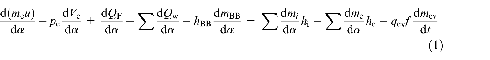
where mc is the mass in the cylinder, u is the specific internal energy, pc is the cylinder pressure, Vc is the cylinder volume, QF is the fuel energy, QW is the wall heat loss, α is the crank angle, hBB is the specific enthalpy of blow-by, mBB is the mass of blow-by, mi is the mass flowing into the cylinder, hi is the enthalpy of the in-flowing mass, me is the mass flowing out of the cylinder, he is the enthalpy of the mass leaving the cylinder, qev is the evaporation heat of fuel, f is the fraction of evaporation heat from the cylinder charge, mev is the evaporating fuel mass, and t is the time. The variation of the mass in the cylinder can be calculated from the sum of the in-flowing and out-flowing masses

Heat transfer affects the performance and efficiency of engine. The Woschni heat transfer model 25 is used to calculate heat fluxes to chamber walls; the calculation of heat transfer coefficient αw is given by

where D is the cylinder bore, Tc is the temperature in the cylinder, c1 = 2.28 + 0.308 cu/cm, cm is the mean piston speed, cu is the circumferential velocity, VTDC is the TDC volume in the cylinder.
For modeling combustion process of engine, Vibe function, 24 which is defined by the start and duration of combustion, a shape parameter and a Vibe parameter, is used to approximate the actual heat release characteristics which were directly obtained from the combustion test. The single Vibe function is described as follows:

where


Q is the total fuel heat input; αo is the start of combustion; Δαc is the combustion duration; m is the shape parameter; a is the Vibe parameter.
The models use equations (1) and (2) to link the in-cylinder processes with the intake and exhaust flows. The one-dimensional unsteady flow equations are used for calculating the details of intake and exhaust unsteady compressible flows, which are numerically solved by the Finite Difference techniques. 26 Moreover, the blow-by mass flow rates are calculated by using an orifice flow modeling, in which the cylinder pressure and temperature are used as the upstream stagnation pressure and temperature while the mean crankcase pressure represents the downstream static pressure.
For the gasoline engine model, these modeling data such as engine torque, fuel flow rate, air fuel ratio, blow-by mass, friction loss, air cleaner performance, the flow coefficient of ports, cylinder pressure, and intake and exhaust dynamic pressures were obtained by a series of rig tests. For the miniature IC engine model, FMEP was calculated from the friction power tested on the bench, and other parameters assembled in the thermodynamic model such as engine configuration, valve timing, equivalence ratio, and so on, were also directly measured or indirectly converted from test data. The simulated combustion pressures are compared with test data in Figure 7, in which the tested combustion pressure is an average of continuously sampled 120 test cycles in combustion diagnosis. The simulation results show a good correlation with the experimental data. Figure 8 demonstrates the comparison of the simulated power and BSFC with those in test data, providing further evidence that the thermodynamic models can well predict the performance of the two IC engines.

The simulation results of combustion pressures compared with the tested combustion pressures: (a) 0.15-L single-cylinder gasoline engine; (b) miniature IC engine. Notation: 1—simulated combustion pressure of the gasoline engine; 2—tested combustion pressure of the gasoline engine; 3—simulated combustion pressure of the miniature IC engine; 4—tested combustion pressure of the miniature IC engine.

Simulation results of engine performances compared with test data: (a) out power; (b) BSFC. Notation: 1—simulated combustion pressure of the gasoline engine; 2—tested combustion pressure of the gasoline engine; 3—simulated combustion pressure of the miniature IC engine; 4—tested combustion pressure of the miniature IC engine.
The thermodynamic numerical models provide a possibility to more completely understand the reasons for the low BMEP and the poor thermal efficiency of the miniature IC engine. Figure 9 indicates the energy conversion path of the miniature IC engine from fuel energy to mechanical energy output. By numerical calculation of the thermodynamic models, the specific characteristic data of in-cylinder mass and energy change on the energy conversion path for both the miniature IC engine and the gasoline engine are indicated in Figure 10.

Conversion path of fuel energy in cylinder.

In-cylinder mass and energy change on the conversion path of fuel energy: (a) gas exchange characteristic ratios; (b) energy conversion characteristic ratios. Notation: 1—fuel trapping efficiency of the gasoline engine; 2—fuel trapping efficiency of the miniature IC engine; 3—volumetric efficiency of the gasoline engine; 3—volumetric efficiency of the miniature IC engine; 5—fraction of mass leakage of the gasoline engine; 6—fraction of mass leakage of the miniature IC engine; 7—indicated power divided by heat energy effectively released in cylinder for the gasoline engine; 8—indicated power divided by heat energy effectively released in cylinder for the miniature IC engine; 9—indicated power divided by actual fuel energy in cylinder for the gasoline engine; 10—indicated power divided by actual fuel energy in cylinder for the miniature IC engine; 11—indicated power divided by trapped fuel energy for the gasoline engine; 12—indicated power divided by trapped fuel energy for the miniature IC engine; 13—output power divided by total energy of fuel added for the gasoline engine; 14—output power divided by total energy of fuel added for the miniature IC engine.
The gas exchange characteristic ratios, including fuel trapping efficiency (the total mass of the fuel effectively trapped in the cylinder divided by the total mass of the fuel added), the fraction of mass leakage (the mass leakage divided by the total mass in the cylinder at start of high pressure cycle), volumetric efficiency (VE), are presented in Figure 10(a). It can be seen that the miniature IC engine (curve 2) has a very poor fuel trapping efficiency (around 60%), that is, more than 40% fuel is lost during scavenging, which makes much greater fuel consumption. The maximum VE of the miniature IC engine (curve 4) is below 50%, much lower than that of the gasoline engine (curve 3). It is why the BMEP of the miniature IC engine is much lower. Also, the mass leakage of the miniature IC engine (curve 6) seems to be more serious than the gasoline engine (curve 5). Both the lower VE and the higher mass leakage have an effect to decrease the net efficiency of the miniature IC engine.
The indicated efficiencies of the gasoline engine (curve 7) and the miniature IC engine (curve 8), which are defined as the indicated power divided by the heat energy effectively released in cylinder, are compared in Figure 10(b). The indicated efficiency of the miniature IC engine is lower than that of the gasoline engine, but it is still exceed 30%, much higher than the test data (around 5%). It seems that the indicated efficiency of the miniature IC engine should not be greatly cut down only due to the lower VE and the higher amount of leakage. Curve 9 (the gasoline engine) and curve 10 (the miniature IC engine) are defined as the indicated power divided by actual fuel energy in cylinder (deducting the fuel energy of blow-by), which consider the effect of incomplete combustion due to the richer mixture on the energy efficiency. It can be seen that the miniature IC engine efficiency is dramatically depressed due to the richer mixture, which is the necessary requirement of stable combustion in the miniature IC engine.
Considering the energy loss due to the leakage, curve 11 (the gasoline engine) and curve 12 (the miniature IC engine), which are defined as the indicated power divided by the energy of the fuel trapped in cylinder (including the fuel energy of blow-by), only negligibly decline compared with the curve 9 and curve 10, respectively. It indicates that the gas leakage has less affection on energy efficiency. Curve 13 (the gasoline engine) and curve 14 (the miniature IC engine) are defined as the output power divided by the total energy of fuel added, which represent thermodynamic net efficiency. For the miniature IC engine, since more than 40% fuel is lost during scavenging, the net efficiency of the miniature IC engine is significantly decreased. It can be seen that curve 14 is significantly decreased compared with curve 12. It indicates that the poor fuel trapping efficiency causes the poor net efficiency of the miniature IC engine. Therefore, besides the gas exchange inefficiency and the gas leakage through the cylinder-piston gap, the more important reasons for the poor net efficiency of the miniature IC engine are the rich mixture and the fuel loss in the scavenging process.
Scaling-down simulation
The thermodynamic models were also used to simultaneously simulate the step-by-step processes of scaling down the 0.15-L single-cylinder gasoline engine and the miniature IC engine, referring to the Similarity Analysis Method of IC engine.27–30 Figure 11 shows the VE and mass flow rate with the different cylinder diameters.

Gas exchange characteristics of the scaled-down IC engines: (a) volumetric efficiency of the scaled-down gasoline engines; (b) volumetric efficiency of the scaled-down miniature IC engines; (c) specific mass flow rate for per unit cylinder volume of the scaled-down gasoline engine; (d) specific mass flow rate for per unit cylinder volume of the scaled-down miniature IC engine. Notation: 1—scaled-down gasoline engine with 40-mm cylinder bore; 2—scaled-down gasoline engine with 30-mm cylinder bore; 3—scaled-down gasoline engine with 20-mm cylinder bore; 4—scaled-down gasoline engine with 10-mm cylinder bore; 5—scaled-down miniature IC engine with 10-mm cylinder bore; 6—scaled-down miniature IC engine with 8-mm cylinder bore; 7—scaled-down miniature IC engine with 6-mm cylinder bore; 8—scaled-down miniature IC engine with 4-mm cylinder bore.
It can be observed from Figure 11(a) that as the engine speed increases, the VE of the gasoline engine quickly declines; but as the cylinder diameter decreases, the VE increases. For example, at the engine speed of 18,000 r/min, the VE increases from 52% to 90% as the cylinder bore are decreased from 40 mm to 20 mm. The effect of engine size on the VE of the miniature IC engine is shown in Figure 11(b). It is clear that engine speed corresponding to the maximal VE is appreciably increased as the cylinder diameter is scaled down. For example, for the cylinder diameter of 8 mm, the engine speed corresponding to the maximum VE is 21,000 r/min; while for the cylinder diameter of 4 mm, the engine speed increases to 46,000 r/min. It seems that the smaller the engine size is, the better the gas exchange characteristic at high engine speed is.
It is interesting to note that the mass flow rate does not always increase linearly as the engine speed increases. As shown in Figure 11(c) and (d), flow chokes apparently at higher engine speeds, which results in the quickly decline of the VE. For per unit cylinder volume, the smaller the cylinder diameter is, the higher the maximum mass flow rate can be reached. For example, in Figure 11(c), the maximum mass flow rate for per unit volume is appreciably increased from 100 g/(s
To research the minimum length scale of a thermodynamically viable scaled-down miniature IC engine, different theoretical assumptions were assembled into the thermodynamic models to calculate the IMEP of the scaled-down miniature IC engines. Figure 12 shows the IMEP of the scaled-down miniature IC engines with cylinder diameters of 6 mm, 5 mm, and 4 mm, including IMEP counting the heat transfer loss and the mass leakage loss (curve 1), IMEP only counting the heat transfer loss (curve 2), IMEP ignoring the heat transfer loss and the mass leakage loss (curve 3), IMEP calculated by ideal Constant Volume Combustion model without the heat transfer loss and the leakage loss (curve 4), IMEP calculated by Otto cycle which is the ideal thermodynamic cycle for the miniature IC engines with 100% volumetric efficiency (curve 5).

IMEP of the scaled-down miniature IC engines: (a) cylinder bore = 6 mm; (b) cylinder bore = 5 mm; (c) cylinder bore = 4 mm. Notation: 1—IMEP counting the heat transfer loss and the mass leakage loss; 2—IMEP only counting the heat transfer loss; 3—IMEP ignoring the heat transfer loss and the mass leakage loss; 4—IMPE calculated by ideal Constant Volume Combustion model; 5—IMEP calculated by Otto cycle.
For the scaled-down miniature IC engines, the most important reason for IMEP diminution is the low efficiency of gas exchange processes, indicated by the difference between curve 5 and curve 4 in Figure 12. The next reason is the imperfection of combustion, indicated by the difference between curve 4 and curve 3. Third is the cutback of IMEP due to the mass leakage of blow-by which is the difference between curve 2 and curve 1. The effect of heat transfer on IMEP is comparatively smaller, which can be shown as the difference between curve 3 and curve 2. As engine speed increases, the effect of imperfect combustion on IMEP increases, and the effect of the mass leakage loss decreases.
As cylinder diameter is scaled down to 4 mm in Figure 12(c), IMEP (curve 1) is only slightly higher in a very small speed range than FMEP (dashed line) which is a fitting curve of the aforementioned test data. It can be deduced that the smallest cylinder diameter is about 4 mm for scaled-down reciprocating IC engine which maybe run at 35,000 r/min to 40,000 r/min. However, because there is so large distance between curve 3 and curve 5 for underway development, it is very possible in future to achieve a meso-scale IC engine with cylinder bore less than 1 mm by improving its gas exchange and combustion processes.
Conclusions
The performance and combustion characteristics of a miniature IC engine with a displacement of 0.99 cc were investigated on a specialized test bench. The power output of the miniature IC engine reaches a maximum of 70 W, and the maximal friction power exceeds 40 W. On the peak power point, fuel flow rate reaches to 300 g/h, and cylinder head temperature increases to 200°C. Combustion diagnosis verifies that the miniature IC engine has high level of cyclic variations, and the combustion behavior is not reasonably well. How to achieve stable combustion in a very small cylinder is an important problem in the development of micro scaled-down IC engine.
The performance of the miniature IC engine was compared with that of four types of conventional size IC engines. It is found that the BMEP of the miniature IC engine does not exceed 300 kPa, which is much lower than that of the conventional size IC engines; and the overall level of fuel consumption and BSFC of the miniature IC engine are much higher than that of conventional size IC engines. However, the FMEP of the miniature IC engine appears to be much less sensitive to the engine speed so that it can run at a higher operating speed, and achieve a superior specific power of 70 W/cc.
A thermodynamic numerical model using the Cycle Simulation Method was developed by combining theoretical and experimental considerations, especially assembling the test data of performance and combustion diagnosis. By numerical calculation of the thermodynamic models, the specific characteristic data of in-cylinder mass and energy change on the energy conversion path are indicated. The important reason for the low BMEP of the miniature IC engine is the poor VE, which is not more than 50%. Besides the gas exchange inefficiency and the gas leakage due to blow-by, dramatic reasons for the poor net efficiency of the miniature IC engine are rich mixture and fuel loss in the scavenging process. Therefore, to develop smaller engines by scaling down conventional size IC engines, efforts should be paid on improving the processes of gas exchange and combustion.
Thermodynamic models were used to simulate the step-by-step processes of scaling down the gasoline engine and the miniature IC engine. As the miniature IC engine is scaled down, gas exchange characteristics become more favorable for higher engine speeds. For the scaled-down miniature IC engines, different thermodynamic theoretical assumptions were used to figure out the factors contributing to the IMEP loss. It is found that the maximum IMEP loss is due to the imperfection of gas exchange processes, the next is the imperfection of combustion, and the third is the mass leakage of blow-by, the effect of heat transfer on IMEP is comparatively smaller.
As cylinder diameter is scaled down to 4 mm, IMEP is almost lower than FMEP in the whole range of engine speed. It can deduced that the smallest cylinder diameter is about 4 mm for the scaled-down reciprocating IC engines, which maybe run at 35,000–40,000 r/min. However, because there is considerable potentiality for improving the gas exchange and combustion processes, it is considered that achieving a smaller IC engine or even a meso-scale IC engine with cylinder bore less than 1 mm is thermodynamically possible.
Footnotes
Declaration of conflicting interests
The author(s) declared no potential conflicts of interest with respect to the research, authorship, and/or publication of this article.
Funding
The author(s) disclosed receipt of the following financial support for the research, authorship, and/or publication of this article: This research was supported by National Natural Science Foundation of China (Grant No. 51175530), Specialized Research Fund for Doctoral Program of Chinese Higher Education (Grant No. 20130191110001), and Science and Technology Research Project of Henan Province (Grant No. 202102210204).