
Abstract
Compared with four-stroke engines, single-cylinder two-stroke engines have the characteristics of small inertia, high rotational speed, and wide excitation frequency range. However, the structural vibration and noise generated by the two-stroke engine are very violent. Hence, it is necessary to reduce the vibration and noise of the single-cylinder two-stroke engine. Based on the design theory of the engine mounting system, the excitation frequency, direction, and magnitude of a single-cylinder two-stroke engine are analyzed. The rubber isolator is selected as the new mount element, and the dynamic model of the engine powertrain mounting system is established based on ADAMS software. Based on the sensitivity analysis of the design variables of the mounting system, the natural frequency of the mounting system is used as an objective, and the three-directional stiffness of the mounting system is taken as design variables for the optimization problem. The optimization model is solved by the sequential quadratic programming method. The results show that the maximum frequency of the mounting system after optimization is less than 1/
Keywords
Introduction
Compared with the four-stroke engine, the single-cylinder two-stroke engine has advantages of simple structure, wide rotating speed range, and high lifting power. However, the structural vibration and noise generated by the two-stroke engine are very violent, which have a great impact on the body of the user and the surrounding environment.1–3 Therefore, it is necessary to reduce the vibration and noise of the single-cylinder two-stroke engine.
Aiming at the problem of large vibration and noise of the two-stroke engine, Mohite and colleagues4–6 used multibody dynamics and finite-element simulation tools to predict the vibration and noise generated by the two-stroke engine for motorcycle, which could effectively predict the vibration and noise in the early design stage and reduce the development cost. The multibody dynamic simulation was used to determine the excitation force and to predict the engine combustion load noise. The vibration reduction balance optimization of the crankshaft is proposed to reduce the vibration of motorcycle touch-sensitive points. Since there are few research studies on the vibration characteristics of small engines, the vibration characteristics of automobile engines can be analyzed for small engines. Aiming at the problem of large vibration of automobile engines, Crocker used the finite-element method to analyze and optimize the vibration and noise characteristics of engines from the perspective of structural optimization. 7 At present, the main method to analyze the vibration characteristics of the single-cylinder two-stroke engine is to use the method of vibration characteristics analysis of an automobile engine.
It is more difficult to reduce the vibration of the engine by optimizing its structure. Therefore, the engine powertrain and its mounting system should be optimized to reduce the vibration transmitted by the engine to the vehicle body. Wu and Shangguan 8 proposed a genetic algorithm and sequential quadratic programming algorithm to optimize the hydraulic engine mounting system, and the vibration transmitted by the engine to the car body was effectively reduced. Kolte et al. 9 used a particle swarm optimization algorithm to optimize the mounting system of a three-cylinder diesel engine. Zhen and Fredrickson 10 analyzed how the mounting system isolates structural energy and the influence of bracket structural stiffness on vibration isolation of the mounting system. Zhang et al. 11 proposed an improved Powell conjugate direction method to optimize the mounting system of a high-speed, heavy-duty engine. Kaul and Dhingra 12 reduced the total transfer rate by optimizing the stiffness, installation direction, and angle of the mounting. Snyman et al. 13 constructed the mathematical model of engine powertrain mounting, taking the mass of a single mounting and the angle of installation as the design variables, taking the vibration transmitted by engine assembly mounting as the objective function, and using the dynamic optimization algorithm to successfully minimize the vibration transmitted by mounting to the support.
To date, many research studies are focused on optimization of the mount system for the four-stroke engine, and there is a lack of published literature in the area of engine mount optimization for the single-cylinder two-stroke engine in a hedge trimmer. In this article, the mount system of a single-cylinder engine used in a hedge trimmer is taken as the research object. Based on the analysis of the vibration characteristics of a single-cylinder two-stroke engine, the engine mounting system is optimized. First, the vibration of the single-cylinder two-stroke engine is analyzed and the vibration isolation of the exiting spring mount system is tested in sections “Vibration isolation theory of a single-cylinder two-stroke engine” and “Vibration analysis of single-cylinder two-stroke engine.” Then, the structure of the mounting system is designed and the dynamic model of the mounting system is established in section “Structural design and dynamic model of mounting system.” Sensitiveness of mounting system parameters is analyzed and optimal design of the mounting system in section “Optimal design of the mounting system.” Giving a brief conclusion, the rubber vibration isolator is selected as the new mounting element. The natural frequency of the mount is used as an objective, and the three-directional stiffness of the mount element is taken as a design variable for the optimization problem. The optimization model is solved by the sequential quadratic programming (SQP) method. The results show that the maximum frequency of the mounting after optimization is less than
Vibration isolation theory of a single-cylinder two-stroke engine
Compared with a four-stroke engine, a single-cylinder two-stroke engine has the advantages of simple structure, wide rotating speed range, and high power per liter. It is often used as a power source of agricultural and forestry equipment, portable generator, water pump, motorcycle, and other equipment. However, the structural vibration and noise produced by the two-stroke engine are very severe, which have a great impact on the user’s body and the surrounding environment.15,16 Optimizing the mounting system is a very effective method to reduce vibration and noise levels for the two-stroke engine. Here, the excitation induced by the single-cylinder two-stroke engine and the vibration isolation design for the mounting system are first analyzed for further optimization.
Excitation induced by single-cylinder two-stroke engine
Figure 1(a) shows a schematic diagram of the crank-connecting rod mechanism of the single-cylinder two-stroke engine. The force diagram of the piston-connecting rod mechanism is illustrated in Figure 1(b). Assuming that the crankshaft rotates at a constant angular speed

where

(a) Movement diagram of the crank connecting rod mechanism and (b) piston linkage force diagram.
For the single-cylinder two-stroke gasoline engine, only reciprocating inertia force and rotary inertia moment can excite the equipment. The reciprocating inertia force of the piston is

where
The excitation frequency range of a reciprocating inertial force is determined by

where nmin is the rotation rate of a single-cylinder two-stroke engine at idle working condition, nmax is the maximum rotation rate of a single-cylinder two-stroke engine, N is the number of cylinders, and Z is the number of strokes.
Mounting system design theory
The single-cylinder two-stroke engine powertrain mounting system is simplified to a 6-degree of freedom (DOF) model, 14 illustrated in Figure 2(a). The engine mount is considered to be composed of three mutually orthogonal one-dimensional elastic materials, with three-direction constant stiffness and damping. The simplified mount element is shown in Figure 2(b). The vibration equation for the engine powertrain mounting system is


(a) Mounting system schematic diagram and (b) dynamic model of mount element.
With the assumption that the mounting system is uncoupled in each direction, the vibration isolation model of the mount system is simplified to a single-degree system, as shown in Figure 3(a). And the amplitude–frequency and phase–frequency characteristics of the system can be easily obtained, as shown in Figure 3(b). It is very apparent that the frequency ratio
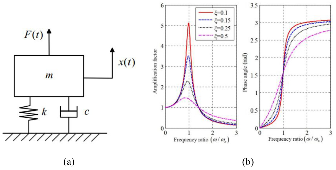
(a) Vibration isolation model of single degree of freedom and (b) amplitude–frequency and phase–frequency characteristics of an elastic system.
Vibration analysis of single-cylinder two-stroke engine
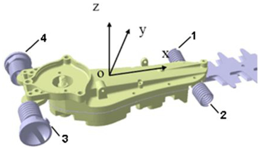
In this article, the mounts for the single-cylinder two-stroke engine in the hedge trimmer are considered. The idle speed of this single-cylinder two-stroke engine is 2600 r/min, and the speed corresponding to the maximum output power is 7000 r/min. Then, the excitation frequency range of the engine varies in 43.33 Hz–116.67 Hz. Four coil springs are taken as the mounts for the single-cylinder two-stroke engine in the hedge trimmer, as shown in Figure 4.

Node position and excitation direction on the engine.
Experimental modal analysis of engine mounting system
The experimental modal analysis is carried out in this section. As shown in Figure 4, the position and direction of the excitation points for the mode experiments are assigned on the engine assembly, and the simplified model in DASP software is given in Figure 5. The method of multiple inputs and single output is employed in this procedure, and node 1 is defined as both the excitation and response points.

Simplified model and nodes on the model.
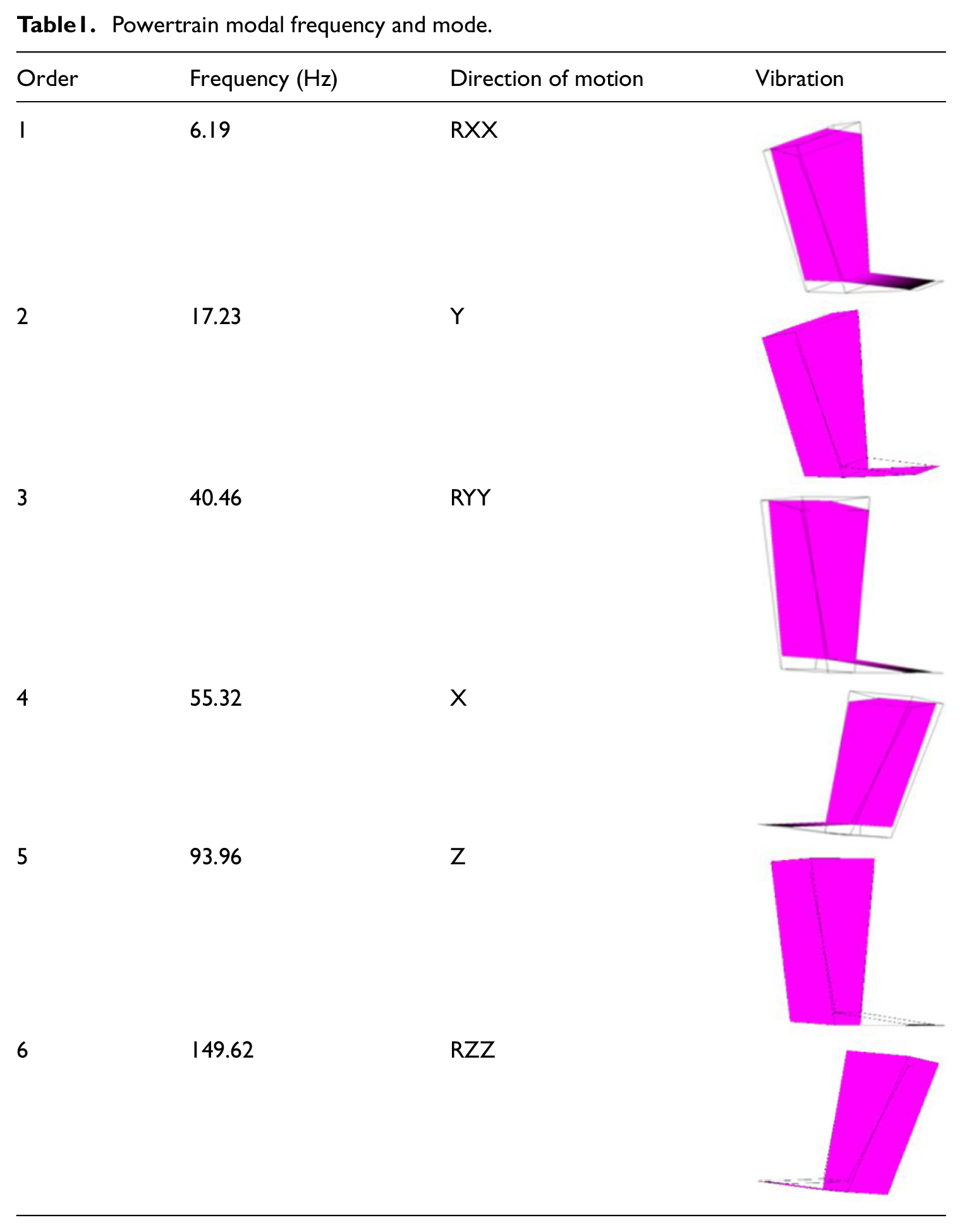
Table 1 lists the natural frequency of the engine mounting system, within the range of 6.19 Hz –149.62 Hz. Obviously, the range is larger than the range of the engine excitation frequency, from 43.30 Hz to 116.67 Hz. It implies that it is easy to cause the resonance of the hedge trimmer, resulting in a strong sense of vibration felt by the users of the hedge trimmer.
Powertrain modal frequency and mode.
Vibration test of hedge trimmer
Figure 6 shows three positions of measuring points for the vibration test of the hedge trimmer. To effectively find the excitation direction that causes the largest vibration, the vibration in different directions is analyzed, under idle and wide-open throttle conditions.

Position of vibration test sensor in the hedge trimmer.
Figure 7(a)–(c) shows the three-direction acceleration of three measuring points under the idle condition. It is very clear that the maximum vibration happens in the X direction. Figure 7(d)–(f) shows the three-direction acceleration of the three measuring points under the wide-open throttle condition. While the excitation frequencies are 55.33 Hz, 93.96 Hz, and 149.62 Hz, the resonances for the engine will happen, and these three frequencies correspond to the natural frequencies of the 4th, 5th, and 6th modes.
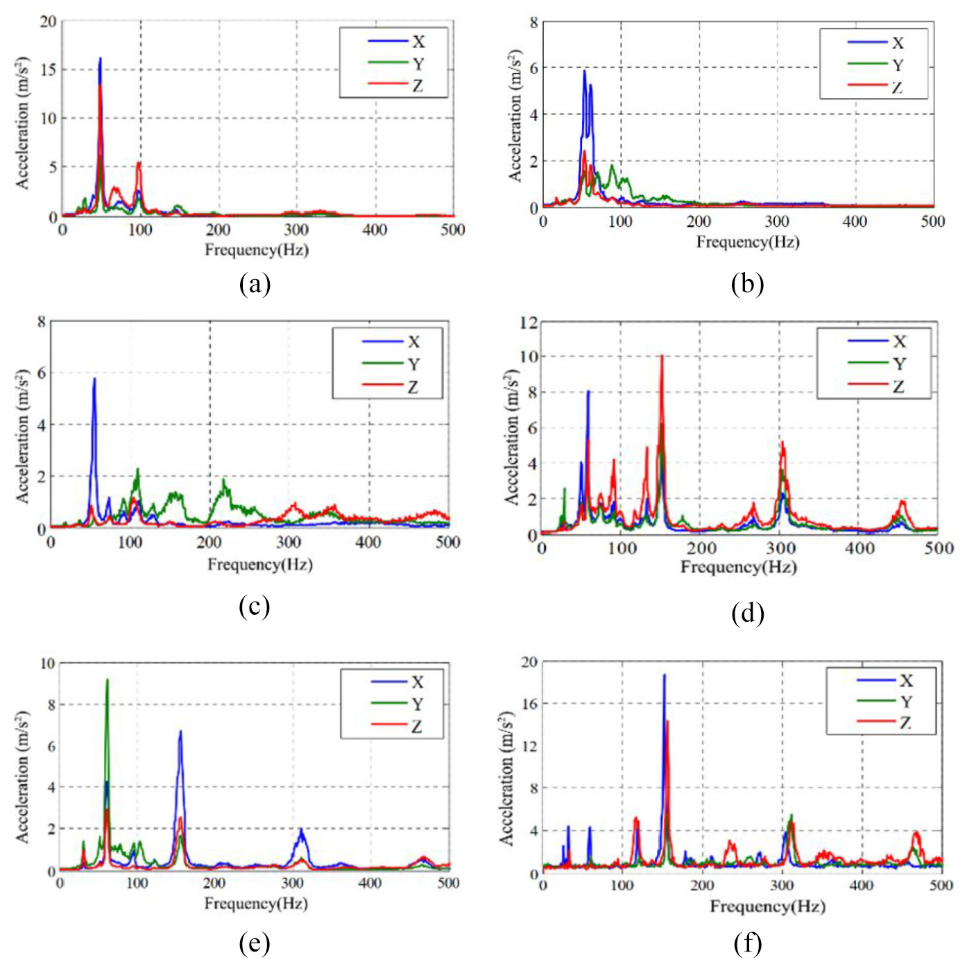
(a) Three-direction acceleration of point 1 under idle condition; (b) three-direction acceleration of point 2 under idle condition; (c) three-direction acceleration of point 3 under idle condition; (d) three-direction acceleration of point 1 under the wide-open throttle condition; (e) three-direction acceleration of point 2 under the wide-open throttle condition; and (f) three-direction acceleration of point 3 under the wide-open throttle condition.
Existing mounting system vibration isolation test
Figure 8 shows the global coordinate system and its numbering for the mounting system. Figure 9 illustrates the local coordinate system of the mount element. The vibration levels of the engine side and the support side of the mount are measured and analyzed. Here, only the vibration accelerations in the X direction are given due to the reciprocating movement direction of a piston is in the X direction.
Installation location of mounting system.

Local coordinate system of mount element.
Figure 10(a)–(d) shows the vibration acceleration of the support side and engine side in the X direction under the idle condition. It can infer that the four spring mounts do not play a role in vibration isolation but increase the vibration acceleration transmitted from the engine to the support. Figure 10(e)–(h) shows the vibration acceleration of support side and engine side in the X direction under the wide-open throttle condition. Similar results can be obtained. Therefore, a mounting system with better vibration isolation is needed.

(a) Mounting 1, vibration acceleration of the X direction under idle condition; (b) mounting 2, vibration acceleration of the X direction under idle condition; (c) mounting 3, vibration acceleration of the X direction under idle condition; (d) mounting 4, vibration acceleration of the X direction under idle condition; (e) mounting 1, vibration acceleration of the X direction under wide-open throttle condition; (f) mounting 2, vibration acceleration of the X direction under wide-open throttle condition; (g) mounting 3, vibration acceleration of the X direction under wide-open throttle condition; (h) mounting 4, vibration acceleration of the X direction under wide-open throttle condition.
Structural design and dynamic model of mounting system
In this section, new mount components are selected, and the corresponding model is established for further optimization. Considering the position and space reserved for the mounting elements on the engine assembly shell and the fixed hedge trimmer support, the newly selected rubber element is installed in the same way as the initial spring elements.18,19,22
Structural design of mounting system
The dynamic coefficient, damping ratio, and the ratio of axial stiffness to radial stiffness of rubber isolators have a large design space. 23 Hence, the JSD rubber vibration isolator is selected as the mount element for the mounting system, as shown in Figure 11(a), and the dimension of the rubber vibration isolator is illustrated in Figure 11(b). For further optimization, the initial parameters are shown in Table 2.

(a) Rubber vibration isolator and (b) size of individual rubber body (mm).
Initial design parameters of vibration isolator.

Dynamic model of mounting system
The dynamic model of mounting system with selected mount elements is established in ADAMS software. The engine assembly and support are simplified as rigid bodies. Hence, the reversal torque caused by the reaction force of four mounting elements can be ignored. Then, the rubber mount component is simplified as a three-direction orthogonal elastic element, without considering the torsional rigidity and torsional damping of the mount. Figure 12 illustrates the dynamic model of the engine powertrain mounting system established in an ADAMS/view module. The blue component represents the engine powertrain, and the red sleeve represents the four mounting elements. Table 3 lists the inertia parameters obtained from the CAD model, and locations of mount elements are listed in Table 4.

Dynamic model in ADAMS platform.
Inertia parameters obtained from CAD model.

Coordinates of mounting elements (mm).

The natural frequency and energy decoupling rate of the mounting system are calculated using the ADAMS/vibration module, and the vibration mode diagram listed in Table 5 can be obtained. The blue model represents the original location of the engine powertrain, and the red model represents the position after vibration. It can be seen from Table 5 that there is a large gap between the natural frequency of each order. Therefore, the energy decoupling rate of the mounting system is close to 100%. Table 5 also lists the natural frequency of the rubber mounting system, from 3.17 Hz to 77.23 Hz. Obviously, the range is more overlap with the range of the engine excitation frequency, from 43.30 Hz to 116.67 Hz. It also implies that it is easy to cause the resonance of the hedge trimmer, resulting in a strong sense of vibration felt by the users of the hedge trimmer. Therefore, the natural frequencies of the mounting system should be reconfigured.
Modal frequency, decoupling rate, and mode distribution of the mounting system.

Optimal design of the mounting system
In this section, the design variables are determined by sensitivity analysis first. And the optimization model for the mounting system is developed. The SQP method is employed to obtain the optimal settings for the mounting system. 20
Sensitivity analysis of mount system parameters
The natural frequencies of the mounting system are selected as design objectives and three-direction stiffness and three-direction damping of the mounting components are considered as initial variables.17,21,24 The sensitivity of the design objective with respect to the design variables are analyzed in the ADAMS/Insight module. Figure 13(a)–(f) shows the results of the sensitivity analysis of the mounting system in terms of natural frequency. It can be concluded that the three-dimensional stiffness of the mounting system has more influence on the natural frequency of the mounting system. Hence, the three-direction stiffness of the mounting elements is determined as the final design variables.

Results of natural frequency sensitivity analysis (a) results of sensitivity analysis in RXX mode; (b) results of sensitivity analysis in RYY mode; (c) results of sensitivity analysis in Y mode; (d) results of sensitivity analysis in RZZ mode; (e) results of sensitivity analysis in Z mode; and (f) results of sensitivity analysis in X mode.
Figure 14(a)–(c) illustrates the results of the sensitivity analysis of the mounting system with reaction force. It can be concluded that the three-dimensional stiffness of the mounting system has more influence on the reaction force of the mounting system. Hence, the three-direction stiffness of the mounting elements is determined as the final design variables.

Sensitivity analysis results of reaction force of mounting system: (a) sensitivity analysis results of average reaction force in the X direction; (b) sensitivity analysis results of average reaction force in the Y direction; and (c) sensitivity analysis results of average reaction force in the Y direction.
Mounting system optimization design
As mentioned earlier, the natural frequency configuration is selected as the design objective, and the natural frequencies of the mounting system should be less than
The optimization model for the mounting system can be stated as follows

Optimization results and discussion
The optimization of the natural frequency of the mounting system is completed by 15 iterations. Table 6 lists the natural frequency of the rubber mounting system after optimization, from 1.12 Hz to 28.31 Hz. It can be concluded that the highest order natural frequency of the mounting system is 28.31 Hz, which is less than 29.55 Hz. Hence, the optimal design of mounting system meets the requirements of vibration isolation.
Modal frequencies and modes of the engine assembly mount system after optimization.
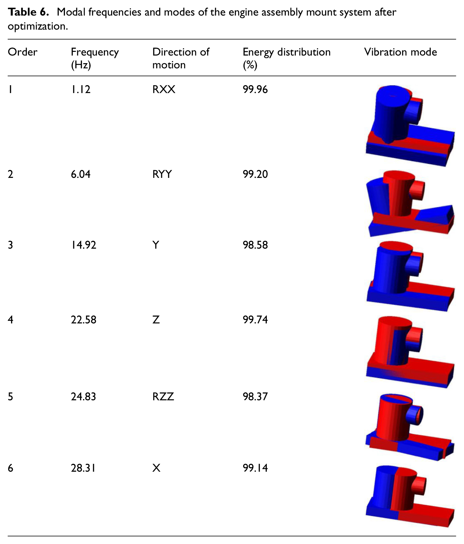
Table 7 lists the stiffness of the mounting system before and after optimization. Then, the support and limit performance of the mounting system is checked. According to the parameters of the single-cylinder two-stroke engine selected in this article, the maximum torque of the engine is 1.2 Nm, which corresponds to the engine speed of 5000 r/min. The maximum power of the engine is 0.85 kW, which corresponds to the speed of 7000 r/min. And the torque at the maximum power can be obtained as 1.16 Nm. The maximum torque was applied to load excitation in the ADAMS model with the excitation frequency of 83.33 Hz and the torque amplitude of 1.2 Nm. According to the excitation expression created in the ADAMS model, the excitation point was located at the center of gravity of the model.
Stiffness values before and after optimization.

Figure 15(a)–(c) shows the results before and after optimization of three-direction reaction force of the mount element. The maximum frequency of the vibration response in the X, Y, and Z directions is 83.33Hz. After optimization, the vibration isolation effect is very well. Figure 15(d) illustrates displacement in the time domain of the mass center of the engine after optimization. The displacement of the centroid in the X and Y directions is less than 0.01 mm, and that in the Z direction is 0.063 mm. Hence, the three-direction displacement is very small, which shows that the optimized mounting system meets the requirements of support and limit.

(a) Comparison of X-direction average reaction force before and after optimization; (b) comparison of Y-direction average reaction force before and after optimization; (c) comparison of Z-direction average reaction force before and after optimization; and (d) displacement of centroid before and after optimization.
Conclusion
Compared with four-stroke engines, single-cylinder two-stroke engines have the characteristics of small inertia, high rotational speed, and wide excitation frequency range. They are often used as a power source of agricultural and forestry equipment, portable generator, water pump, motorcycle, and other equipment. However, the structural vibration and noise generated by the two-stroke engine are very violent, which have a great impact on the body of the user and the surrounding environment. Hence, this article presents a method to reduce the vibration transmitted from engine to engine support by optimizing the natural frequency of the mounting system. Through the vibration test of the hedge trimmer and the vibration isolation performance test of the spring mount element, the natural frequency of the mounting system, within the range of 6.19 Hz –149.62 Hz, is larger than the range of the engine excitation frequency, from 43.30 Hz to 116.67 Hz. It implies that it is easy to cause the resonance of the hedge trimmer. Hence, the rubber vibration isolator is selected as the new mount element. The sensitivity analysis of the natural frequency of the rubber mounting element and the reaction force of the mounting system shows that the three-direction stiffness has the greatest influence on the natural frequency and reaction force of the mounting system. The natural frequency of the mount is taken as a design objective, and the three-direction stiffness of the mount element is taken as a design variable for the optimization problem. The optimization model is optimized by using the SQP method. These results show the natural frequency of the rubber mounting system after optimization, from 1.12 Hz to 28.31 Hz. The highest order natural frequency of the mounting system is 28.31 Hz, which is less than 29.55 Hz. Hence, the optimal design of the mounting system meets the requirements of vibration isolation.
The dynamic model and the optimization method presented in this article would provide a useful tool for the design and optimization of the mounting system for the single-cylinder two-stroke engine to reduce vibration from the engine to the engine support.
Footnotes
Declaration of conflicting interests
The author(s) declared no potential conflicts of interest with respect to the research, authorship, and/or publication of this article.
Funding
The author(s) received financial support for the research, authorship, and/or publication of this article: This study was supported by the Science and Technology Committee of Shanghai Municipal Key Project (18060502400).