
Abstract
With strong demands of energy-saving and environment-friendly vehicles, hydraulic hybrid powertrain is a suitable solution for urban transportation. This article proposes a novel hydraulic hybrid vehicle with wheel motors to improve vehicle power performance and fuel economy. A forward-looking simulation model of the vehicle is built. System parameters are determined according to the power performance demands. A smaller engine is chosen, the peak power of which is reduced by 11.96%. The simulation model is calibrated and verified by experimental tests on the designed test bench. Parameterized simulation results indicate that the acceleration time 0–100 km/h of the designed vehicle is decreased by 36.3% from 19.63 to 12.5 s compared with the conventional vehicle. The maximum vehicle speed is 140 km/h, and the maximum gradeability is 29%. When the engine works in economy mode, fuel consumption is decreased by 35.59% from 15 to 9.66 L per 100 km on the Urban Dynamometer Driving Schedule cycle compared with the conventional vehicle.
Introduction
Energy consumption and environment protection have become increasingly important, and thus are drivers for developing energy-saving and environment-friendly vehicles. New energy vehicles1,2 and hybrid powertrain vehicles3–5 are the main solutions. However, new energy vehicles have not found an acceptable solution with safety, stability and low cost. The hybrid powertrain vehicle has become a concerned technical solution to reduce energy consumption and pollution emissions. 6 The hybrid powertrain vehicle has gained research interest as a short- and mid-term solution worldwide.
Hybrid vehicles refer to vehicles with two or more energy storage systems, both of which must provide propulsion power either together or independently.7,8 Hybrid vehicles mainly use internal combustion engines (ICE) as main power sources and other components as auxiliary energy devices. The main types of hybrid vehicles are electric hybrid, mechanical hybrid and hydraulic hybrid. Hydraulic hybrid is concerned by its high power density. 9 Vehicle fuel economy can be improved by effective regenerative braking, especially for frequent start–stop conditions like city drive cycles. 10 When providing the same output power, hydraulic components have smaller volume and lighter weight compared with others, which are beneficial to achieve spatial layout and vehicle lightweight, respectively.
At present, there are mainly three types of hydraulic hybrid vehicles: series, parallel and series-parallel, as shown in Figure 1. Specific comparison is as follows.
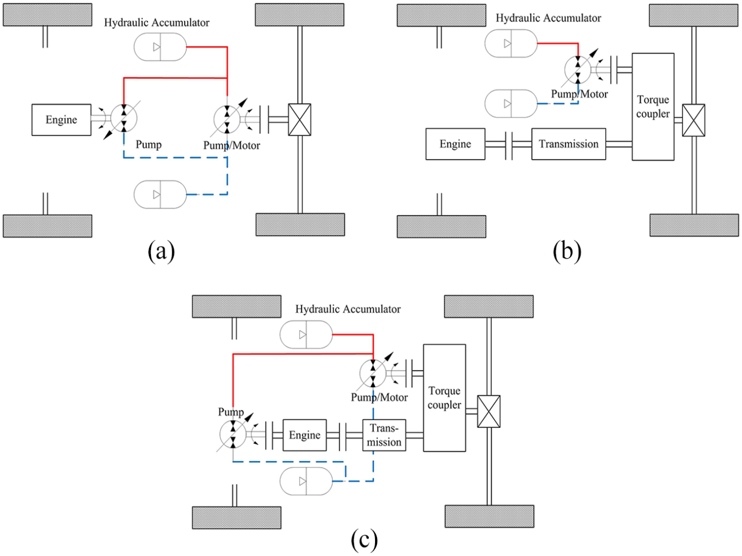
The structure principle of typical hydraulic hybrid vehicles: (a) series type, (b) parallel type and (c) series-parallel type.
A series hybrid can decouple between engine and driving condition. The mechanical transmission parts of a traditional vehicle are annihilated. Engine can work in best performance conditions, which can effectively improve fuel economy and reduce pollution emissions. 11 It is easy to realize the continuously variable transmission (CVT) and drive/brake integrated control. 8
A parallel hybrid has many engineering applications due to its advantages of easy refitting and high transmission efficiency.12,13 However, an engine does not have full freedom to decouple with driving conditions compared with the series type. Therefore, the optimization is limited and the energy-saving efficiency is not as high. Furthermore, it does not possess the advantages of CVT.
A series-parallel hybrid has the advantages of both series and parallel types. 14 It can possess the best performance advantages of a hybrid powertrain under different driving situations. Therefore, fuel economy has the potential to be improved. 15 However, its structure is complicated, and reliability of components is highly required. Its control system should ensure smooth switch during mode changes.
Hydraulic hybrid technology has been applied by medium, heavy and engineering vehicles. In recent years, applications of this technology to light vehicles, urban transport vehicles and sport utility vehicles (SUVs) have also become increasingly popular because of the development of hydraulic components. 16 The United States Environmental Protection Agency (EPA) pays attention to the research of hydraulic hybrid technology over the years.6,17 The hydraulic hybrid technology development process of the EPA is shown in Figure 2. 18 The developing trend is from auxiliary drive used in heavy vehicles to full hydraulic drive applied in light vehicles.

The hydraulic hybrid technology development process of EPA.
In the past, many researchers have performed relevant studies about hydraulic hybrid vehicles. The efficiency of a series hydraulic hybrid vehicle is relatively low. In series hybrids, the internal combustion engine cannot directly drive the wheel, but must pass the two losses of mechanical energy to the hydraulic energy and the hydraulic energy to the mechanical energy. In some cases, the efficiency of the internal combustion engine directly driving the wheel is in fact higher. In addition, a high-power hydraulic motor is required because the motor must be able to drive the vehicle alone in all situations. It is not easy to meet the power performance requirements of a full-size SUV with four-wheel drive. Achten et al. 19 designed a series hydraulic hybrid vehicle with hydraulic transformers to achieve all-wheel drive, but system efficiency was mostly determined by hydraulic transformers. High-efficiency hydraulic transformers are hard to realize. Peter 20 proposed a wheel-drive hydraulic hybrid vehicle with hydraulic transformers and constant pressure system which had the same problem. Wei 21 designed a hydraulic hybrid SUV with all-wheel drive, but front and rear drive axles were still reserved. The efficiency of the system needs to be improved. Therefore, it is meaningful to design a new type structure with simple structure and high efficiency.
Wheel motors are important parts in a hydraulic hybrid vehicle with wheel motors. When driven by in-wheel motors, part of the transmission mechanism is eliminated. The structure of the vehicle is simple and the transmission efficiency is high, which is beneficial to the space layout of the whole vehicle. In addition, the traction force and climbing capacity of the vehicle can be improved by working with in-wheel motors. 22
In this article, a novel hydraulic hybrid vehicle with wheel motors is proposed to improve vehicle power performance and fuel economy. In section ‘System design and operating principles’, the structures and operating principles of the vehicle are introduced. In section ‘System modelling’, a forward-looking simulation model is built. In section ‘Model validation’, a test bench is designed and the simulation model is calibrated and validated by experimental tests. In section ‘Simulation results and analysis’, vehicle acceleration time, maximum vehicle speed, maximum gradeability and fuel economy are simulated and analysed. The results are compared with the conventional vehicle.
System design and operating principles
A novel hydraulic hybrid vehicle with wheel motors is proposed to improve vehicle power performance and fuel economy. The proposal is shown below. This designed vehicle can work in drive and brake mode, and its operating principles are designed.
System configuration
The proposal eliminates the mechanical transmission parts of a traditional vehicle, and hydraulic power system is applied. Four wheels are directly rotated by four variable displacement wheel motors. This vehicle can decouple between engine and driving condition. Engine can be downsized due to the auxiliary drive of high-pressure accumulator. Vehicle fuel economy can be improved significantly by recovering the braking energy. In addition, vehicle dynamics, minimum ground clearance and off-road performance can be improved due to four variable displacement wheel motors. Its simplified schematic is shown in Figure 3.
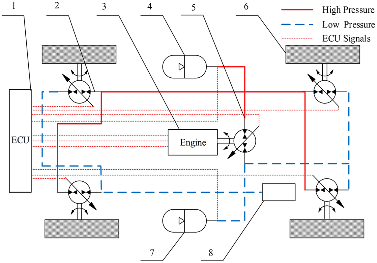
Schematic of a novel hydraulic hybrid vehicle with wheel motors.
Operating principles
The proposed vehicle can work in drive and brake mode, and its energy transfer path is shown in Figure 4.
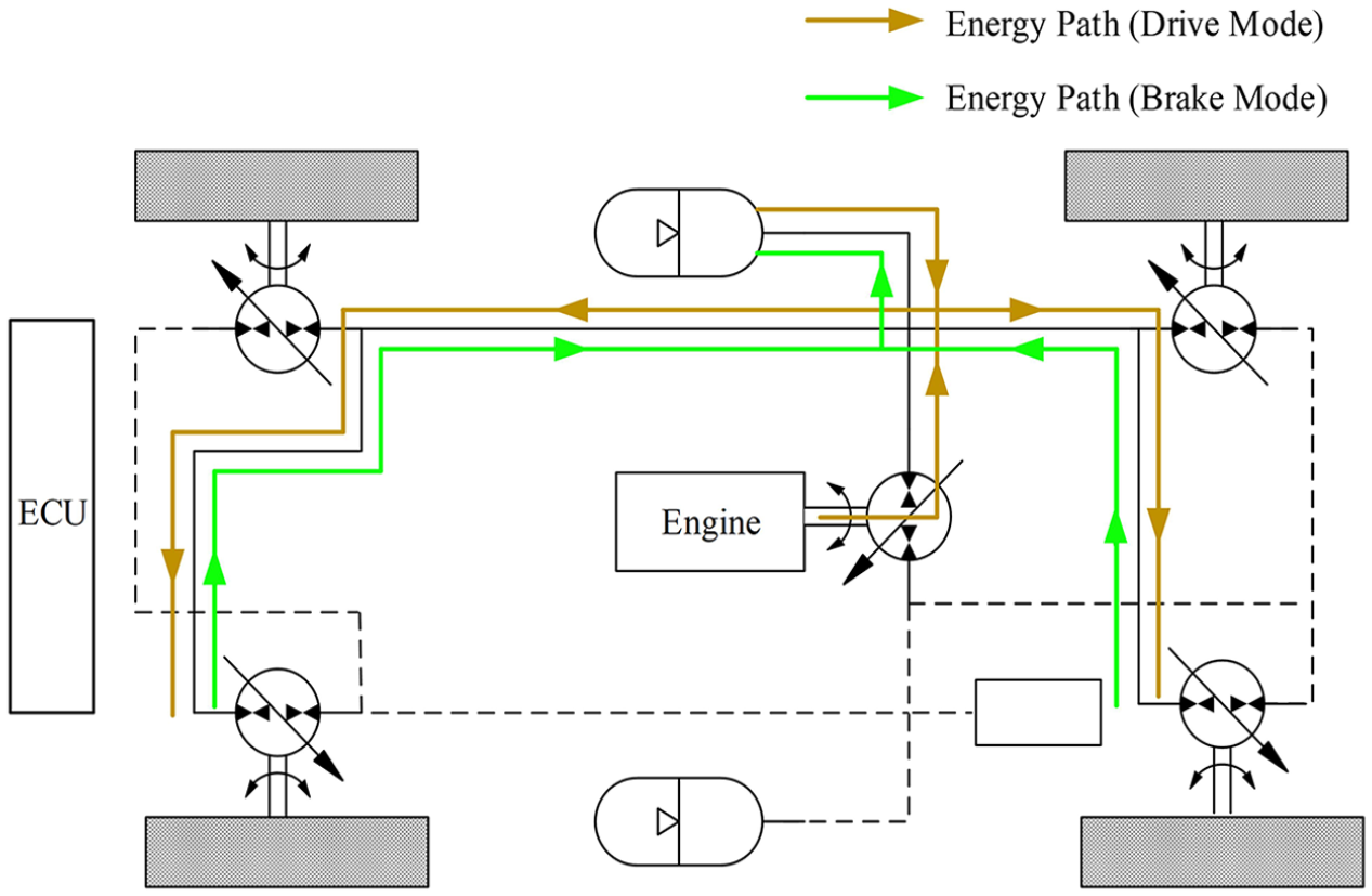
Energy transfer path in drive and brake mode.
Drive mode
(1) The electronic control unit (ECU) detects the pressure of the accumulator when starting or accelerating. If the pressure is lower than a certain lower limit, the engine works and drives the variable displacement pump to supply high-pressure oil to the hydraulic system. If the pressure is higher than the upper limit, the accumulator independently supplies high-pressure oil to drive variable displacement wheel motors; meanwhile, the engine idles or shuts down. The engine and the high-pressure accumulator can work together to offer output power when rapid acceleration occurs. Therefore, engine peak power can be decreased. This proposal can overcome the shortcomings of low efficiency and large pollution emissions of engine during starting and accelerating. (2) When driving at a constant speed, there are two conditions according to the pressure of accumulator. If the pressure is lower than a lower limit, the engine works in best fuel economy area. Excess high-pressure oil is stored in the accumulator. Otherwise, the accumulator releases energy and the engine idles or shuts down. Therefore, the engine works in best performance area intermittently. (3) During reverse driving, the ECU detects reverse gear signal, and then the rotational direction of variable displacement wheel motors is changed. Its energy transfer path is the same as forward driving.
Brake mode
The ECU detects brake pedal signal, and then the engine idles or shuts down immediately. The variable displacement pump no longer provides the hydraulic system with high-pressure oil. The ECU adjusts the displacement of the wheel motor to negative value. The variable displacement wheel motor works as a pump driven by the inertia of vehicle. Therefore, the kinetic energy is converted into hydraulic energy and stored in the high-pressure accumulator. When the high-pressure accumulator is full, excess high-pressure oil will flow back to low-pressure reservoir through relief valve. It causes oil temperature to rise rapidly. At this point, traditional brake system should work immediately.
System modelling
A forward-looking simulation model is designed based on the forward-looking simulation method. A simulation block diagram is shown in Figure 5. The simulation model of the vehicle is divided into three parts: body model, diver model and controller model.

Block diagram of the forward-looking simulation model.
Body model
Body model mainly consists of an engine, a variable displacement pump, variable displacement wheel motors, a hydraulic accumulator and a vehicle dynamics model.
Engine model
A numerical model is built, instead of building a complicated theoretical model of engine. Engine universal characteristic function is obtained by a great deal of data from dynamometer tests. The engine mathematic model is


where
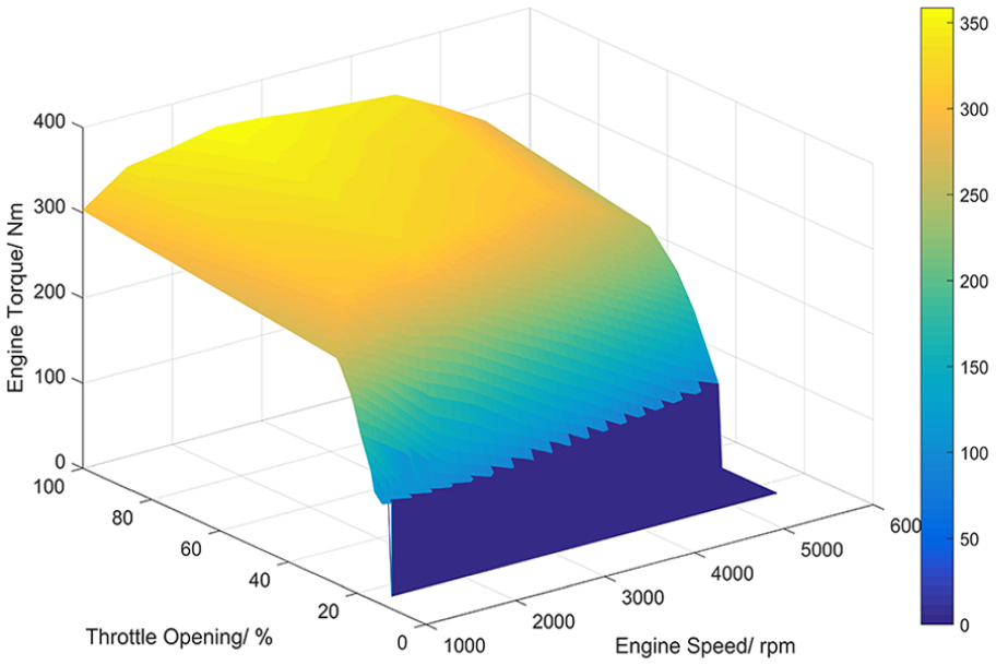
Engine numerical model.
Variable displacement pump and motor model
Hydraulic pump converts mechanical energy into hydraulic energy, and its performance directly affects the reliability and stability of the hydraulic system. The displacement of hydraulic pump and motor can be adjusted according to the working conditions. Variable displacement pump mathematic model is


where


where
Hydraulic accumulator model
The main function of the hydraulic accumulator is to store and release hydraulic energy. Bladder hydraulic accumulator is widely used because of its sensitive reaction, reliable sealing, long cycle life and large energy density compared with other types of accumulators. In this article, bladder hydraulic accumulator is used, and its simulation model is built according to the Boyle–Mariotte law

where
The variation rate of accumulator volume is accumulator flow rate, which is the flow continuity equation. The flow continuity equation is an expression of the law of conservation of energy in fluid mechanics

where
Vehicle dynamic model
When driving, the vehicle has to overcome driving resistance, including rolling resistance, air resistance, gradient resistance and accelerating resistance. The overall driving resistance can be expressed as


where
When accelerating, the vehicle needs to overcome the inertia force produced by its mass acceleration, which is accelerating resistance. The mass of vehicle is simulated by flywheel in the model so that accelerating resistance need not be recalculated.
Driver model
Under real conditions, the driver only needs to operate accelerator pedal, brake pedal, gear selection (forward, neutral or reverse) and mode selection (economy or power). A driver model is established. The function of accelerator pedal stroke and desired vehicle speed is determined. For simplicity, the desired vehicle speed is considered as a linear function with accelerator pedal stroke


where
Similarly, vehicle speed difference is considered as a linear function with brake pedal stroke. The desired vehicle speed is expressed as the current vehicle speed minus vehicle speed difference, as shown in equation (20)


where
Controller model
Driver/brake system
The core component of the drive/brake system is the variable displacement wheel motor. When driving or braking, the vehicle speed controller controls the displacement of the variable displacement wheel motor on the basis of actual vehicle speed and desired vehicle speed. Correspondingly, the variable displacement wheel motor output torque and driving force on wheels are changed, so vehicle speed is controlled by vehicle speed controller. The desired vehicle speed is acquired according to driver’s operation from driver model, and actual vehicle speed is calculated by the vehicle dynamics model. In this article, the vehicle speed controller uses a proportional–integral–derivative (PID) controller (Figure 7).

Simulation block diagram of the drive/brake system.
Power source system
The power source system mainly consists of an engine, a variable displacement pump and a high-pressure accumulator. A simulation block diagram of power source system is shown in Figure 8. The control process is summarized as follows:
The first controller is called upper controller, and it calculates the required power of the variable displacement wheel motor based on signals from oil pressure and flow sensors.
The working status and desired power of engine are determined according to the driver’s gear selection and power management strategy which is decided by the upper controller.
The engine operating mode (economy or power) is decided by the driver’s mode selection. Then, the desired operating point of the engine is determined from look-up tables.
Throttle opening is adjusted by the electronic throttle model. Actual engine output torque is found in look-up tables (see engine model). Then, the torque is applied to variable displacement pump. Engine actual operating point is determined by actual throttle opening and actual engine speed.
The variable displacement pump model calculates actual pump speed that is the actual engine speed.
The engine speed controller makes the engine track aim at engine speed by changing the displacement of variable displacement pump according to engine speed error.
In this article, the engine speed controller uses a PID controller.

Simulation block diagram of the power source system.
The forward-looking simulation model of the vehicle
For simplicity, four wheel motors are the same. A forward-looking simulation model of a novel hydraulic hybrid vehicle with wheel motors is built based on body model, driver model and controller model, as shown in Figure 9.

The forward-looking simulation model of the vehicle.
System parameters
The system parameters are determined based on a conventional vehicle. Table 1 shows the main structural and technical parameters of the conventional vehicle, which are obtained from a series of relevant tests by the automobile manufacturer. Power performance demands of the designed vehicle are the same as the conventional vehicle. The system parameters are determined, as shown in Table 2.
Main parameters of conventional vehicle.

System parameters of the designed vehicle.
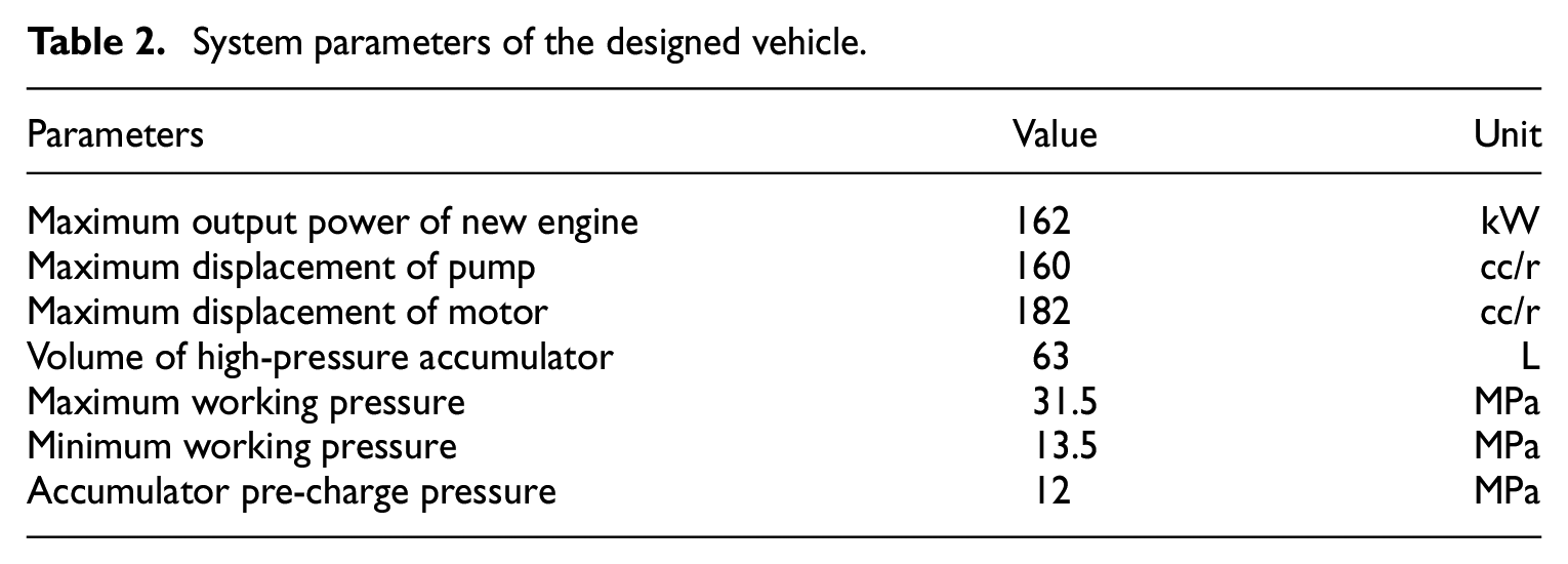
The vehicle mass is a key simulation parameter. The designed vehicle eliminates the mechanical transmission parts of a conventional vehicle. Although the hydraulic drive system is added, its vehicle mass is a little decreased compared with the conventional vehicle. Therefore, the vehicle mass is the same as the mass of the conventional vehicle, which makes sure that the designed vehicle and conventional vehicle have the same conditions for performance comparison.
Model validation
A simulation test platform for semi-physical simulation is of fundamental significance. According to the proposed vehicle structure and its working principles discussed in this article, a hydraulic system test bench is designed. The simulation model is calibrated and verified by experimental tests.
Test bench design
The schematic of the hydraulic system test bench is shown in Figure 10. The variable frequency electric motor is used to simulate the operating conditions of the engine. Motor frequency converter controls the variable frequency electric motor. Magnetic powder brake is used to simulate the driving resistance of the vehicle. Flywheel simulates the vehicle mass. Based on the system parameters presented in Table 2, components are selected to build the physical test bench, as shown in Figure 11.
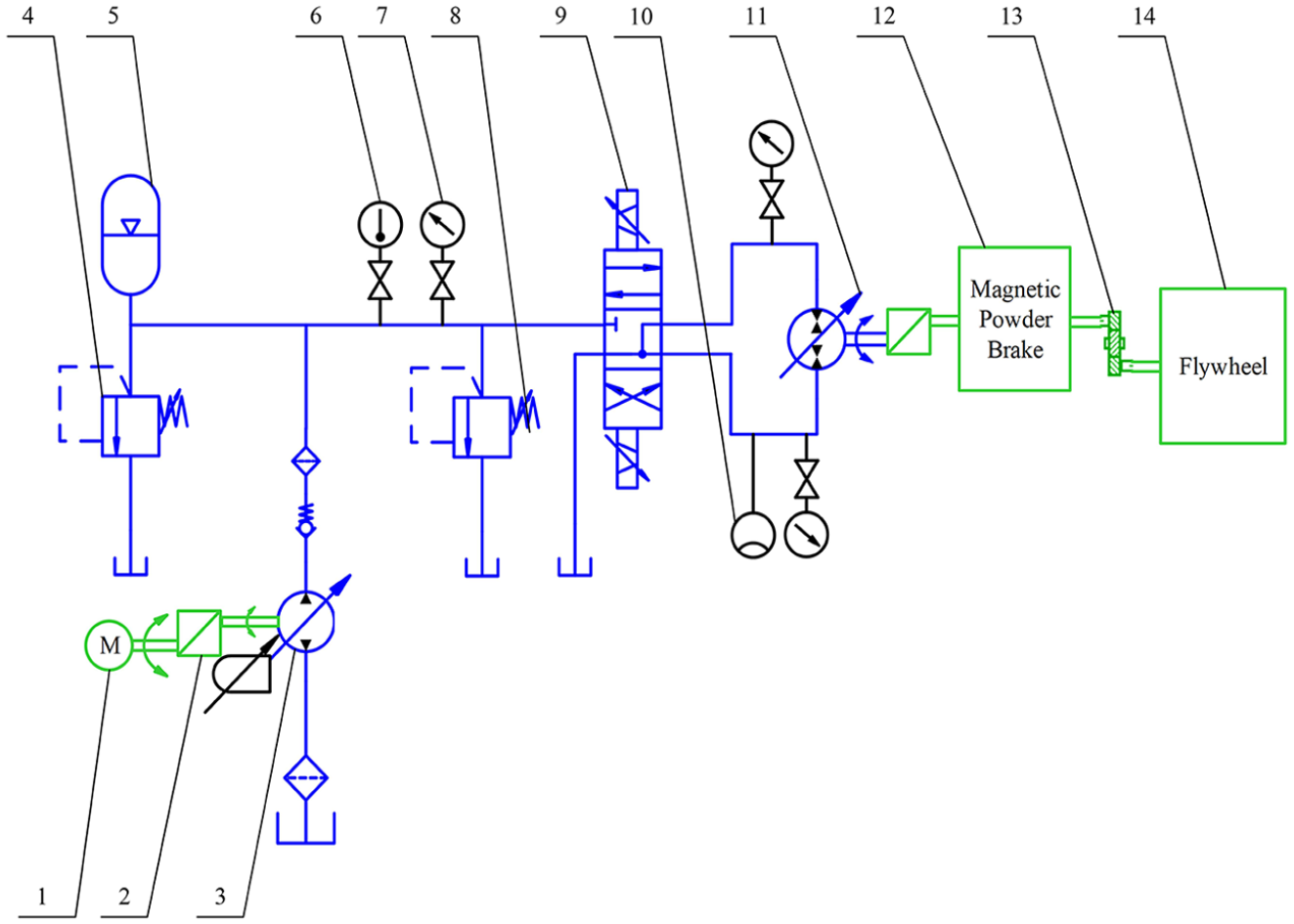
Schematic of hydraulic system test bench.

Hydraulic system test bench.
Results and analysis
The self-designed test bench and simulation model are given the same initial values to calibrate and testify the simulation model. When driven by the high-pressure accumulator alone, the initial conditions are as follows: variable frequency electric motor and engine are off, the pressure of the high-pressure accumulator is 19 MPa, the flywheel speed is 0 r/min and the displacement ratio of the variable displacement wheel motor is 1. Simulation and experimental results are compared in Figures 12 and 13.

Comparison of pressure variation when accelerating.
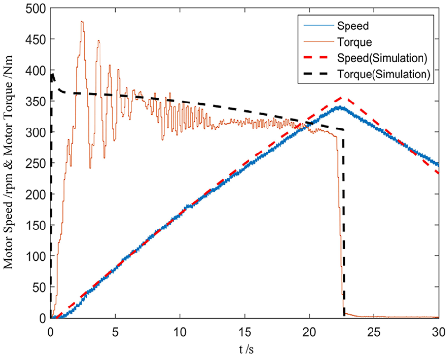
Comparison of motor speed and torque variation.
When charging the high-pressure accumulator from 19 to 25 MPa by electric motor or engine, the initial conditions are as follows: the electric motor and engine speed is 1000 r/min, the pressure of the high-pressure accumulator is 19 MPa, the displacement ratio of the variable displacement pump is 1 and the variable displacement wheel motor is off. The charging performance of the high-pressure accumulator is compared in Figure 14.

Comparison of pressure variation when charging high-pressure accumulator.
Observed from the above comparison diagrams, the curves of experiment and simulation results are nearly matched and the error between simulation and experiment is small. The simulation model is proven to be accurate.
Simulation results and analysis
The simulation model parameters are set up according to Table 2. The designed vehicle must first guarantee to meet the power performance demands when the vehicle is equipped with a smaller engine whose peak power is reduced by 11.96%. The typical cases are simulated and analysed.
Acceleration time
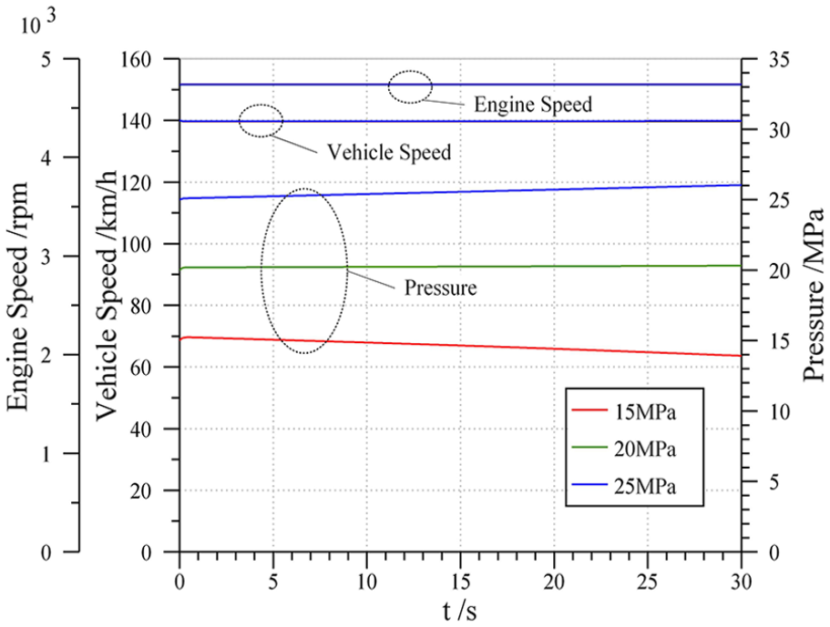
The vehicle is driven by engine and accumulator together. Set the initial state: the engine works at a maximum power of 162 kW and speed of 4736 r/min, the vehicle speed is 0 km/h and the pressure of the high-pressure accumulator is separately set to 15, 20 and 25 MPa. Simulation results are given in Figures 15 and 16.

Variation of engine speed, vehicle speed and pressure with time.
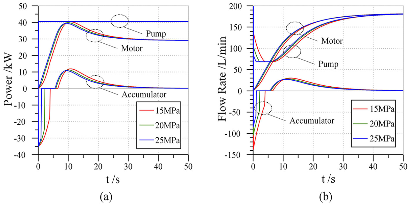
Balance diagram of pump, motor and accumulator at acceleration mode: (a) power balance and (b) flow rate balance.
The higher the initial pressure of high-pressure accumulator, the shorter the acceleration time. The engine works at maximum power all the time. At the beginning, the vehicle-needed power is less than the engine output power. The high-pressure accumulator is charged by excess power, and its pressure rises. When the high-pressure accumulator is full, excess energy flows back to the low-pressure reservoir through a relief valve. When vehicle speed increases, the demanded power is greater than the engine output power. The high-pressure accumulator assists and co-drives with the engine. System pressure drops and the vehicle is accelerated to maximum speed (Figure 17).

Comparison of acceleration time.
The acceleration time of the conventional vehicle from 0 to 100 km/h is 19.63 s and that of the designed vehicle is 12.5 s. The designed vehicle has greater accelerating performance, that is, a 36.3% improvement.
Maximum vehicle speed
Maximum vehicle speed is a long-term stable driving condition. If driven by high-pressure accumulator independently, hydraulic system pressure drops with the release of the hydraulic energy. The energy is limited and vehicle cannot run a long period of time. Therefore, the working state is that the vehicle is driven by the engine alone. Variable displacement pump output power is equal to vehicle-needed power. The engine works at maximum output power. The vehicle speed can be accelerated to 140 km/h under different pressures, as shown in Figure 15.
Set the initial state: the engine maximum power is 162 kW and speed is 4736 r/min, the vehicle speed is 140 km/h and the pressure of the high-pressure accumulator is set to 15, 20 and 25 MPa (Figure 18).
Variation of acceleration, vehicle speed and pressure with time.
The vehicle runs steadily at a maximum speed of 140 km/h. The engine works at maximum output power, and its speed is invariant all the time. High-pressure accumulator pressure and the displacements of motor and pump remain unchanged. Under different pressures, the vehicle is always in a steady state. Maximum vehicle speed has nothing to do with the pressure of the hydraulic system, but is influenced by maximum engine power and motor power.
Maximum gradeability
The vehicle overcomes rolling resistance and air resistance. The surplus power is used to overcome gradient resistance to climb the largest slope.
The initial conditions: the engine works at a maximum power of 162 kW and speed of 4736 r/min, the pressure of the high-pressure accumulator is 31.5 MPa and the wheel motor displacement ratio is 1. The maximum gradeability under different vehicle speeds (the lowest limit of 5 km/h) is calculated (Figures 19 and 20).

Variation of maximum gradeability with vehicle speed.
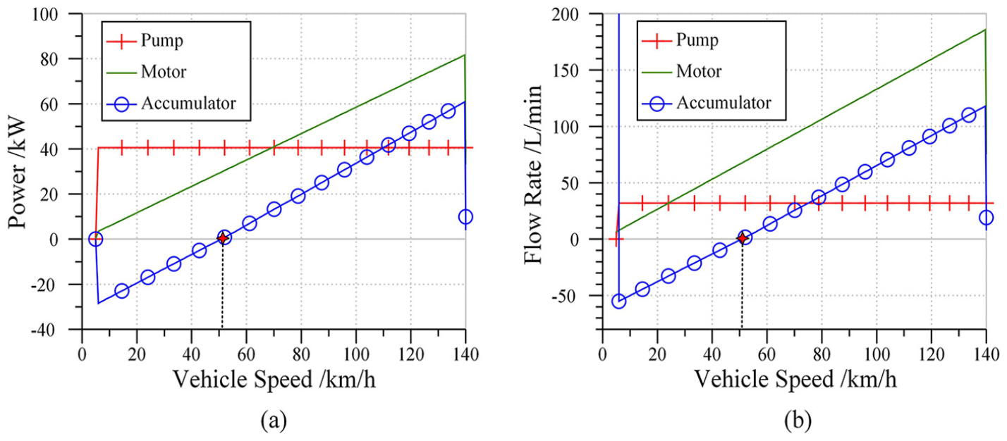
Balance diagram of pump, motor and accumulator at maximum speed mode: (a) power balance and (b) flow rate balance.
The maximum gradeability is 29%, and it decreases as vehicle speed increases. When vehicle speed is low, engine output power is greater than the motor consumed power and the high-pressure accumulator does not release energy. The maximum gradeability is limited by the maximum displacement of wheel motor. The maximum gradeability can be improved by increasing its displacement. When the vehicle speed is 50.5 km/h, maximum engine power is completely consumed by the motor. The power and flow rate of the accumulator are both equal to 0; this is the threshold value of long-term stable operation. If speed is greater than 50.5 km/h, the motor consumed power is greater than the maximum engine power. The high-pressure accumulator assists to drive. The maximum gradeability is still limited by the maximum displacement of motor. However, the auxiliary drive of high-pressure accumulator is not stable. When energy is released, system pressure declines. At this time, maximum gradeability only means that it has the ability to reach that value, but not a stable or long-term situation.
To research the influence of pressure on maximum gradeability, different initial pressures are simulated and compared (Figure 21).
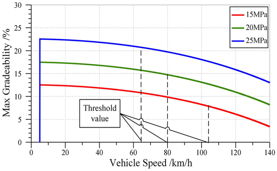
Variation of maximum gradeability under 15, 20 and 25 MPa with vehicle speed.
The initial pressure of the high-pressure accumulator has a great influence on maximum gradeability. The higher the pressure, the greater the maximum gradeability. The vehicle speed threshold values under different pressures are different. The corresponding values of 15, 20 and 25 MPa are 105, 80 and 64 km/h, respectively. The higher the initial pressure, the smaller the stable vehicle speed threshold value. When variable displacement wheel motor output power is constant, its flow rate and pressure are inversely proportional. The flow rate is equal to the product of motor speed and motor displacement. Motor displacement is constant and motor speed is positively related to vehicle speed. Therefore, the threshold vehicle speed is inversely proportional to the pressure.
If the engine is off, the vehicle is driven by the high-pressure accumulator alone, and the vehicle has a very short time duration instead of a steady state.
Fuel economy
Vehicle fuel economy performance is simulated based on the operating principles discussed in section ‘Operating principles’. The lower limit of high pressure is 20.7 MPa and the upper limit value is 24.3 MPa. The simulation cycle is the Urban Dynamometer Driving Schedule (UDDS). This cycle simulates an urban route with frequent starts and stops for light vehicles. 24 The results are shown in Figure 22.

System behaviour of the UDDS cycle.
Actual vehicle speed follows the UDDS cycle. The high-pressure accumulator is charged by an engine at the beginning. The engine works intermittently during the cycle. The UDDS cycle is 1370 s and 11.78 km, and the fuel consumption of the cycle is 1.138 L. Therefore, fuel consumption per 100 km is converted to 9.66 L. The fuel consumption is decreased from 15 to 9.66 L per 100 km compared with conventional vehicle. The fuel economy is improved by 35.59%.
The engine operating mode is selected to economy mode. Engine actual working points are nearby the Min. BSFC (brake-specific fuel consumption) Line during the whole UDDS cycle (Figure 23). The engine is controlled to work intermittently, and the designed controller is validated.

Brake-specific fuel consumption (BSFC) map and working points.
Vehicle performance comparison
Vehicle performance comparison results are listed in Table 3.
Comparison results.

Conclusion
A novel hydraulic hybrid vehicle with wheel motors is designed to improve vehicle power performance and fuel economy. The forward-looking simulation model is built. A test bench is designed, and the simulation model is validated by experimental tests.
Simulation results indicate that the maximum vehicle speed is 140 km/h, the maximum gradeability is 29% and 0–100 km/h acceleration time is 12.5 s. The power performance of the designed vehicle matches demands, and its accelerating performance is improved by about 36.3%. The fuel economy is analysed under the UDDS cycle. Engine actual working points are nearby Min. BSFC Line when the engine works in economy mode. The vehicle fuel economy is improved by 35.59% compared with the conventional vehicle.
In the future study, the complicated energy management strategies of the vehicle will be studied based on the simulation model and test bench designed by this article. A real test vehicle will be designed.
Footnotes
Declaration of conflicting interests
The author(s) declared no potential conflicts of interest with respect to the research, authorship and/or publication of this article.
Funding
The author(s) disclosed receipt of the following financial support for the research, authorship and/or publication of this article: This work was supported by the National Natural Science Foundation of China (Grant No. 51875290).