
Abstract
In order to perceive the state of the process of reverse thinning spinning of the ultra-thin wall tube, a monitoring method based on drum shape is proposed. The method uses the non-uniform rational basis spline curve fitting method based on the moving least squares method to reconstruct the outer contour data of the spinning zone collected by the line laser displacement sensor and extracts the outer contour curve of the drum zone according to the spinning characteristics. Then, the dynamic time warping algorithm is used to analyze the similarity between the current and previous drum curves in order to judge whether the current spinning state is abrupt or not. At the same time, the current spinning state is judged by combining the curvature comb of the drum curve, the number of convex areas of the drum curve, the drum ratio, and the drum change trend. Finally, the drum shape detection and the spinning condition monitoring experiments are carried out. The experimental results show that this method can obtain the outer contour shape of the drum section at one time, and the accuracy is 0.05 mm with respect to the measured value of the three coordinates. The method can realize the visual monitoring of the abrupt change of the spinning process by judging the similarity of the drum curve at the adjacent time under different spinning states. In the state of instability, the curvature comb of the drum curve is discontinuous, the curve is G0 continuous, the drum ratio exceeds the critical drum ratio 2.0, and there is more than one convex region, which realizes the monitoring of spinning state more accurately. The experimental results verify the correctness of the proposed method and prove that the method can be used as a new method to judge the stability of the ultra-thin-walled cylinder spinning process.
Keywords
Introduction
The thinning spinning has the advantages of complete structure, good comprehensive performance, high material utilization rate and short spinning stroke, and so on. It has become one of the preferred manufacturing methods for thin wall tubes used in aviation, aerospace, and nuclear power fields. In the spinning process of an ultra-thin wall cylinder, the combination of simulation and experiment and the quality of spinning forming are studied around the process method, process parameters, and spinning wheel geometry parameters. The spinning deformation mechanism of a thin-walled cylinder is discussed, and the stability of spinning process is improved by various process means and experimental methods. However, due to the low rigidity of the ultra-thin wall cylinder, the parameters obtained from the experiments have poor adaptability to the spinning process system, and the spinning process is prone to abnormal conditions. In order to grasp the spinning situation more intuitively and assist the stable spinning process, a research scheme for monitoring the state of the ultra-thin wall cylinder spinning process is proposed.
In the condition monitoring of thin-walled cylinder spinning process, scholars mainly take the spinning pressure, spindle position, and spinning wheel status of thin-walled cylinder as the monitoring object and study the relationship between spinning parameters and forming quality, in order to optimize the process parameters and the boundary conditions, so as to enhance the stability of spinning process, which has become one of the research directions for the monitoring of the spinning condition of thin-walled cylinders. For example, Romero et al. 1 used infrared imaging and moment monitoring technology to detect the forming process, which provided detection methods and reliability data for laser-assisted spinning. Sugita and Arai 2 used the rotary encoder and pressure sensor to obtain the position of the spinning wheel and the spinning pressure during the spinning of the metal plate into a cylindrical cup, which generates the track of the roller and assists in the stable spinning of the shaped member. Sangkharat and Dechjarern 3 used a pressure sensor to measure the spinning force and studied the influence of key parameters such as spindle speed, feed rate, and reduction on the spinning force and deformation. By adjusting the parameters to control the spinning pressure, stable spinning was achieved. The above research established the relationship model between the forming quality and the stress state of spinning process by simulation. The spinning force is used as the monitoring quantity to realize the auxiliary determination of the spinning process state, but the determination of the state is not clear and needs a lot of experimental data to verify the model. The process detection based on product shape and position information is more visual, and the corresponding spinning state determination is more reliable to assist in the stabilization of the spinning process. For example, Polyblank and Allwood 4 set a laser scanner to monitor the shape of the current workpiece, determine the position of the three internal support rollers, and compensate the rebound amount in real time in combination with the error requirements to achieve more accurate spinning. Xu et al. 5 indirectly deduced the force of the spinning wheel by measuring the position of the spindle through the mandrel deviation acquisition system, in order to maintain the balance of the mandrel, control the feed and the thinning value of the spinning wheels, and improve the forming accuracy of the thin-walled cylinders. Rentsch et al. 6 used the optical three-dimensional digital technology to measure the intermediate process of the spinning workpiece and the geometrical information of the final result, evaluate the quality and effectiveness of different numerical modeling methods, and combine the numerical simulation to obtain the optimal process parameters to guide the stable spinning of the metal sheet.
According to the research ideas of Polyblank and Allwood4 and Rentsch et al. 6 and the spinning characteristics of thin-walled cylinder, the change of workpiece shape in spinning can better reflect the change of spinning state, so the spinning state can be judged by monitoring the workpiece shape. In the spinning process of thin-walled cylinder, the drum phenomenon occurs in the non-spinning area in front of the spinning wheel, which accompanies the thinning spinning process of the thin-walled cylinder. This drum phenomenon is related to the state of spinning process7,8 and can be used as a process feature of state detection and judgment.
The nuclear power CAP1400 stator shielding sleeve has the large length-to-diameter ratio and the large diameter-to-thickness ratio characteristics (outer diameter (ϕ) 624 ± 0.07 mm, wall thickness 0.4–0.5 mm, material C-276), and the spinning process is easy to lose stability, which affects the quality of spinning products. Therefore, under the background of CAP1400 stator shielding sleeve, taking the spinning process of the ultra-thin wall cylinder with small diameter (from 2 to 0.5 mm) as the research object, the monitoring and stability determination method of spinning process based on the drum detection is discussed, which provides methods and data for improving the production of products with a large aspect ratio and a large diameter-to-thickness ratio.
Spinning and drum shape
Thinning reverse spinning
The principle of the ultra-thin wall tube thinning reverse spinning is shown in Figure 1. The ultra-thin wall cylinder is set on the mandrel, one end is restrained, one end is free, and rotates with the spindle of the spinning machine rotating at an angular velocity ω. The single or multiple spinning wheels radially extrude the thin-walled cylinder and then feed in the axial direction, causing local plastic deformation of the contact area between the spinning wheel and the thin-walled cylinder; as the loading position of the spinning wheel is continuously changed. The thin-walled cylinder produces continuous plastic deformation to achieve thinning.

The principle of ultra-thin wall tube thinning reverse spinning.
Drum shape and spinning state
As shown in Figure 1, when the thin-walled cylinder is spinning, the contact area between the spinning wheel and the workpiece is plastically deformed. As the loading position of the spinning wheel changes continuously, the workpiece undergoes continuous plastic deformation, and the material continuity is squeezed to the front side of the spinning wheel, creating a “wedge effect” between the mandrel and the workpiece7,8 (Figure 2).

Wedging effect.
Due to the effect of the wedging effect, the flow direction of the material in the upper and lower layers on the front side of the spinning wheel is changed. A “locking ring” in close contact with the mandrel appears in the rolling deformation zone at the bottom of the spinning wheel.7,8 The upper layer material flows toward the restraining end to form a “drum shape,” and the longitudinal cross-sectional contour shape is skewness distribution, the two ends are low, the middle is high, and the characteristics are single peak and left and right asymmetry. The drum shape and the clamping ring are two phenomena appearing in pairs in the thin-walled cylinder spinning. The formation of the corresponding clamping ring has a very important influence on the formation of local dynamic effective boundary constraints and guiding material flow orientation during the spinning process.
In the process of thinning spinning, a loading cycle is completed, and the geometric interference zone formed by the relative movement of the spinning wheel and the workpiece constitutes a transfer unit of the thinned material. The axial, radial, and tangential projection surfaces of the material transfer region are the contact areas of the spinning wheel for axial, radial, and tangential loading of the workpiece. The feed rate, reduction, and geometry of the spinning wheel determine the three directions’ contact area and the proportional relationship. The three-directional projection of the material transfer unit in spinning process is shown in Figure 3. The clamping ring, the spinning wheel, and the mandrel together form a constraint boundary of the extrusion zone. Wherein, the circumferential sides and the restraining end of the extrusion zone provide deformation resistance, and the material of the extrusion zone is directed to the free end for directional rheology, so that the material restraint boundary of the local pressing zone and the metal flow deformation form a real-time equilibrium state. Under the strong constraint of the stable boundary, the equivalent stress of the deformation zone presents a neat boundary; there is a high stress gradient in the three constraint directions, and the material flows to the free end stably due to the low stress gradient at the free end, and the spinning process is stable (Figure 4(a)). When the mode-locking ring is uneven and the shape of the drum changes, the effective boundary constraint of the spinning zone is missing, and the equivalent stress flow caused by the extrusion plastic deformation penetrates the spinning wheel extrusion control zone. The rheological zone cannot establish a convergent stress–strain field, the boundary is disordered, the rheological direction of the material is out of control, and the spinning process is unstable (Figure 4(b)).

The three-directional projection of the material transfer unit in spinning process: (a) axial direction projection, (b) tangential direction projection, and (c) radial direction projection.

Stress field of the deformation zone: (a) stability and (b) instability.
The shape of the drum that occurs during the thinning process of the thin-walled cylinder is the most direct reflection of the spinning state, and it is also the product of the boundary constraint and the real-time dynamic balance of the metal rheology during the spinning process. It reflects the adaptability of the thin-walled cylinder spinning process parameters to the current working conditions. The continuity of the drum shape means the stationary state of the spinning process. The sharpness, unevenness, and drum height of the drum shape reflect the stability of the current spinning. Therefore, in the spinning process of the ultra-thin wall cylinder, the spinning process monitoring method using the drum shape as the research object is adopted.
The drum profile detection
Detection system
Combining the shape and position of the drum, the line laser displacement sensor based on the laser triangulation measurement principle is selected, and the drum shape detection system based on the horizontal spinning machine is built. The drum monitoring model of the spinning zone is shown in Figure 5. The system is mainly composed of a set of line laser displacement sensor, three sets of eddy current displacement sensors, angle encoders, data transmission modules, and data-processing modules. When the spinning starts, the trigger pulse signal is sent to the sensor by the angle encoder. From this, the trigger line laser displacement sensor detects the shape of the drum outline and the eddy current displacement sensor detects the rotation error.9,10 The data collected by the sensor is transmitted to the computer via Ethernet. The rotation error in the line laser displacement sensor is removed,9,10 and the drum curve data are acquired.

Drum monitoring model of the spinning zone.
Setting and measurement
According to the detection model, the outer contour information of the drum longitudinal section during the spinning process is obtained by the line laser displacement sensor. The relationship between the line laser displacement sensor and the workpiece coordinate system is shown in Figure 6.

Drum profile curve detection.
As shown in Figure 6, the distance H between the linear laser displacement sensor and the mandrel is adjusted by taking the mandrel with radius R as the reference and combining the axial and radial measurement range of the linear laser displacement sensor (H value is determined by the Z measurement range of the linear laser displacement sensor), so that the measurement data of the linear laser displacement sensor on the mandrel are 0. The measurement coordinate system of the laser displacement sensor is set to Osxszs, the end face is set to the z-axis zero point, and the x direction is the width direction of the beam, the vertical mandrel axis, and the zs positive direction away from the mandrel direction. In this coordinate system, the change of the distance between each point of the line laser in the z direction and the core axis is measured. Combined with the x-coordinate data of each point, the shape of the outer contour of the longitudinal section of the drum is obtained by the curve fitting method. If a three-dimensional model of the drum outer contour is required, the axial distance Lj of the sensor and the mandrel restraining end, the mandrel radius R value, and the height value of each detecting drum curve can be converted into three-dimensional coordinate values in the Omxmzm coordinate system and combined with this three-dimensional coordinate value; the three-dimensional model of drum shape in a certain position state is obtained by using the surface reconstruction algorithm.
Curve fitting
Based on the characteristics of the non-uniform rational basis spline (NURBS) curve shape preservation and smoothness, and combined with the local processing ability of moving least squares method,11–13 the NURBS curve fitting method based on the moving least square method is selected to fit the profile curve of the spinning section.
NURBS is a non-uniform rational B-spline curve, and the kth NURBS curve expression is14,15
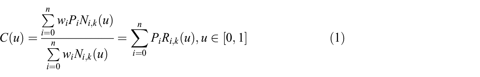
where
According to the Debord-Cox recursion formula,

Specify 0/0 = 0.
When constructing a moving least square NURBS curve, it is necessary to parameterize the parameter values
The moving least squares method constructs an approximate objective function by minimizing the weighted sum of squares of the differences between the corresponding node function values C(uj) and the data points. In the case where, given m+1 measurement data points,

where
A minimum value for

Finishing the above formula

Let
In order to test the accuracy of the method for the discrete point fitting curve, three typical curves (parabolic curve, oscillation curve, and normal probability distribution curve) were selected, and 800 points(the number of points collected by the line laser displacement sensor) were randomly collected at a certain interval. The curve is fitted and compared with the theoretical curve. The fitting accuracy is shown in Table 1.
The accuracy of the typical curve fitting.

It is known from Table 1 that the fitting accuracy of the parabolic curve is about 0.012 mm, that the normal distribution curve is about 0.015 mm, and that the oscillation curve is about 0.022 mm; the fitting accuracy of the corresponding curve decreases as the complexity of the curve increases. The drum curve appearing during the spinning process of the thin-walled cylinder is relatively simple, and the shape is like a normal distribution curve under the condition of stable spinning, and the oscillation curve is equivalent to the oscillation curve under the state of spinning instability. According to the fitting precision of the above curve, the NURBS curve fitting method based on the moving least squares method can be applied to the fitting application of the drum profile curve.
Drum shape extraction
In order to ensure the integrity of the spinning zone, the data collected by the line laser displacement sensor include the free end spin section, the spinning section, the drum section, and the section where the restraining end has no spinning. Combined with the characteristics of spinning, the diameter of the spin section is expanded due to the elastoplastic deformation and the stress release of the material. In the spinning section, due to the extrusion of the thin-walled cylinder by the spinning wheel, the wall thickness becomes thinner and is tightly attached to the mandrel. The drum section has different degrees of convex state due to various parameters of the spinning process and the influence of the process system. The constrained end section is basically in the initial state because the deformation is not obvious.
According to the above feature, the drum portion is between the two critical points between the spinning portion and the undeformed portion of the restraining end. According to the characteristics of the boundary on both sides of the drum section, the maximum points of the fitting curve are determined first, and then, the extreme points of the curves on both sides of the point are obtained by taking the point as the demarcation point, and the minimum points on both sides are taken as the starting and ending points of the drum region, respectively. The drum curve extraction results are shown in Figure 7.
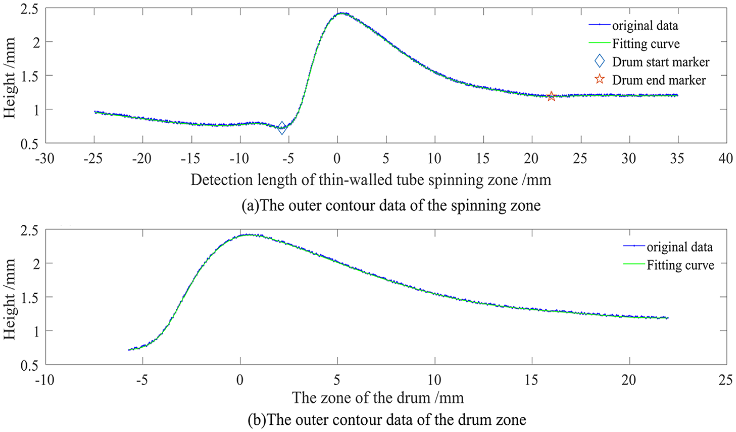
Drum curve extraction.
Evaluation of spinning state based on drum shape
Mutation monitoring in spinning process
During the spinning process of the thin-walled cylinder, the drum-shaped state on the front side of the spinning wheel changes in real time as the spinning progresses. In the stable spinning state, the drum shape changes in the adjacent short time range have continuity and similarity; if the drum shape changes greatly, there may be a sudden change in the spinning process, which will cause the spinning process instability.
The detected drum curve can be regarded as a time series, and the comparison of the drum curves at adjacent moments becomes a similarity measure of two time series. The most common is the point-to-point lock-step 16 metric based on the Euclidean distance (ED). 17 However, the ED requires the two sequences to be measured to be equal in length. For a large time series of datasets, it is difficult to calculate the corresponding ED, and the accuracy is low. 18 For this reason, an extended method based on ED is not to use the original time series directly but to use the features extracted from the original time series, that is, to use Fourier coefficients to represent the time series. Fourier descriptor is widely used in medical field because of its rotation, scale, and translation invariance. 19 In addition, the similarity between time series can be calculated using the feature model extracted from the time series. 20 The core is to study the feature model of two time series and then use its parameters to calculate the similarity value. For example, Ramoni et al. 21 proposed a Bayesian algorithm for clustering time series. They transform each sequence into a Markov chain and then cluster similar chains to produce a process set. If the two sequences or curves to be compared have sequence asymmetry, the above method is inaccurate. For this reason, scholars have proposed a measurement method based on editing distance and dynamic time warping (DTW), which can compensate for the two time series to achieve similarity comparison. For example, in Kholmatov and Yanikoglu, 22 some symbols (i.e. gaps) are added to the two sequences, and the two sequences with different lengths are arranged into the same lengths, thus realizing one-to-one comparison. Marteau 23 takes into account the difference of time stamps, which can deal with time series with different sampling rates and has faster retrieval speed. The DTW method is a classical method of calculating the similarity between two time series. It also allows the points in the time series to undergo equal-length matching after self-replication, supports time series translation, and can flexibly process multi-phase time series. It has been used in countless jobs such as retrieving similar shapes from large image databases, 24 matching incomplete time series in medical applications, 25 aligning signatures in identity authentication tasks, 22 and so on.
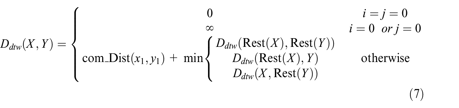
Therefore, according to the time-varying of the drum shape in spinning process, by comparing the drum shape at the current spinning moment with that at the previous moment, the DTW algorithm 26 is chosen to determine the similarity of the drum curve formed at two moments in order to judge the inheritance of the spinning state between the current moment and the previous moment. Therefore, according to the time-varying of the drum shape in spinning process, by comparing the drum shape at the current spinning moment with that at the previous moment, the DTW algorithm is chosen to determine the similarity of the drum curve formed at two moments in order to judge the continuity of the spinning state between the current moment and the previous moment. The DTW algorithm is a method to measure the similarity between the two time series. It is widely used in speech recognition, behavior recognition in computer vision, image processing, data mining, and information retrieval,27,28 Based on the idea of template matching, it can solve the similarity between any two time series. The principle of the DTW algorithm is shown in Figure 8.

DTW principle.
The two solid lines shown in Figure 8 represent two data sequences, and the dashed lines connect the similar points between the sequences. The DTW algorithm calculates the composite value of the distance between all similar points to measure the similarity between the two sequences. The formula for calculating distance is as follows
where
The steps of using the DTW algorithm to determine the similarity of drum contour curves obtained at two different times are as follows:
Let the drum contour discrete data at two different times be sequence
Calculate the ED
In the matrix D, the shortest path from d11 to dnm is searched by the recursive algorithm, and the length of the shortest path Lmin(n, m) is calculated. The length of the initial position is set to Lmin(1, 1) = D(1, 1). The length of the any position is set to Lmin(i, j) = min{Lmin(i, j− 1), Lmin(i− 1, j), Lmin(i− 1, j− 1)} +D(i, j).
The length Lmin(n, m) of the shortest path is taken as the similarity of the drum profiles X and Y at two times.
Spinning state determination
Monitoring the similarity of drum curve at the adjacent time of spinning process can realize the judgment of spinning process smoothness, but it cannot accurately judge the current spinning process state. Combining the relationship between the spinning state and drum shape, the curvature, concave convexity, and drum height of the fitting curve in drum area are analyzed, and the shape characteristics of the curve are evaluated to provide more representative data for judging the current spinning process state. The stability judgment process of spinning process based on drum shape is shown in Figure 9.
Curvature and curvature comb of the drum curve.
29
Curvature and curvature comb can better reflect the curve quality and provide important information for the shape of the spinning drum. Where the curvature is larger, the shape of the curve is more complex, whereas the smaller is relatively flat. The more uniform the curvature comb line shows, the smoother the curve is. When the curvature comb has an obvious angle at some local positions and the length of the curvature comb changes obviously, the drum curve is in G0 continuity and is in danger of folding. First, the fitted drum curve is uniformly discretized, and the first derivative


where

Combining formula (9) and formula (10), and selecting d as the scaling factor, the expression of the curvature comb is obtained as shown in formula (11)

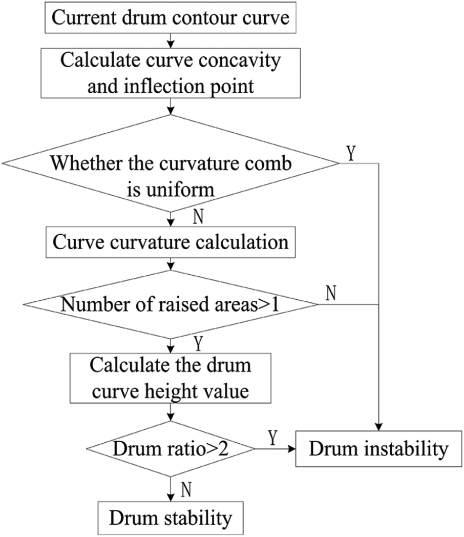
Drum shape judgment process.
During the stable spinning process of the thin-walled cylinder, the shape change of drum outline is continuous, and the drum curve is smooth and without sharp points. When unstable factors occur, the drum curve has sharp and wrinkle characteristics, indicating that the process of spinning has been unstable.
2. The number of the convex areas on the drum curve. The drum curve in the stable spinning state is high in the middle and low in both ends and is shaped like a skewed distribution. Combining the curve concavity and derivative knowledge, the second derivative of the drum curve is calculated, and the concave and convexity of the drum curve is discriminated by comparing the magnitude relationship between the second derivative and zero; the number of convex areas of the curve is also calculated. If the number of convex areas exceeds 1, the spinning process is unstable. Based on the above judgments, the state of the spinning process is judged from the shape of the drum.
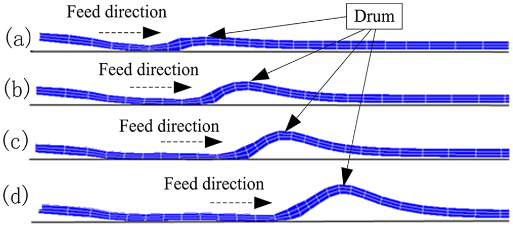
3. Drum height and the drum shape ratio. According to the spinning characteristics of the thin-walled cylinder, when the drum height reaches a certain critical value, the drum shape instability will cause the spinning process to be unstable. Therefore, the drum height can be further used as a quantitative standard for judging stability. However, the thin-walled cylinders of different wall thicknesses have the different drum heights during the spinning process and thus have different critical drum heights, so that the more accurate judgment of the spinning process state does not form a uniform standard value. Combined with the research in Li et al., 8 the drum ratio (h/t) 7 combines the characteristics of wall thickness and drum height, which can reflect the deformation degree of the drum-shaped area and has a relatively constant value. In order to determine the uniformity of the reference, the critical drum ratio can be used as a quantitative criterion for discriminating the spinning state. Therefore, according to the characteristics of material C276, the spinning simulation and spinning test are carried out on thin-walled cylinders with initial wall thickness of 2, 1.5, and 1 mm, respectively (Figure 10). The critical drum height and critical drum ratio of spinning process are extracted and calculated. The corresponding statistical values are shown in Table 2.

The phenomenon of drum shape in the process of spinning: (a) stable drum shape and (b) unstable drum shape.
The drum shape data of thin-walled cylinders with different wall thicknesses in spinning simulation and actual processing mode.

Table 2 shows that although the critical drum height of the thin-walled cylinders with different initial wall thicknesses varies greatly during spinning, the critical drum shape ratio is basically around 2.0 and relatively fixed, and because the critical drum shape ratio takes into account the information of the wall thickness and the drum height of thin-walled cylinders, it can reflect the deformation degree of the drum and the state of spinning process. Therefore, the critical drum ratio is chosen as the quantitative evaluation criterion for the stability of the current spinning process. Combining with the safety of spinning process and spinning experience, the critical drum ratio of the material is 2.0.
Experiments
According to the principle of drum shape detection and the judgment method of spinning process, a set of laser displacement sensor LJ-V7200 (Z axis range: 200 ± 48 mm, repeat accuracy: 1 µm, X: shaft width: 62 ± 11 mm, repeat accuracy: 0.02 mm), three sets of eddy current displacement sensor ZA21 (China Aviation Corporation, within the range 0–4 mm, and the linearity is ±0.3%), and angle encoder SF60A (Incremental encoder of SICK company in Germany) are selected to build a simple test bench for drum shape detection and spinning process state monitoring (Figure 11).

Spinning machine and detection device.
The thin-walled cylinder with diameter of 200 mm and initial wall thickness of 2 mm is selected. The thin-walled cylinder with a thickness of about 0.5 mm is planned to be thinned by three-pass spinning. The drum shape of the thin-walled cylinder during thinning spinning is completed by the spinning test bench and detection device mentioned above.30–32 In this article, the shape of the outer contour of the spinning zone during the third pass spinning process is selected to analyze the spinning process state of the thin-walled cylinder.
Drum curve detection
The drum curve is the data basis for the monitoring of the thin-walled cylinder spinning process. The accuracy of the detection indirectly affects the accuracy of the spinning state evaluation. The linear laser displacement sensor and coordinate-measuring instrument are used to detect the same drum section of the thin-walled cylinder after the third spinning, and the measured difference between the two methods is obtained by the curve matching method.
Early matching technology mainly focused on using the contour of the curve itself to match, which is sensitive to the shape of the curve. For example, Gueziec and Ayache 33 pre-smooth and resample the curve when matching the curve; Kishon et al. 34 mainly approximated curves by splines and then searches similar curves by the least squares hashing technique. Later, scholars considered the characteristic properties of the curve and applied some feature-based methods to the curve matching. For example, Sebastian et al. 35 comprehensively considered arc length and curvature as two attribute comparison curves. Alt et al. 36 studied the geometry matching algorithm based on the Hausdorff distance. The algorithm can achieve better matching of point set and line set data, but it is easy to be interfered by noise points and proportional transformation. Cohen and Guibas 37 put forward the problem of partial-to-partial matching under Euler transformation and proposed that curvature of the arc length should be regarded as an invariant identifier. However, this method cannot make similar changes (translation, rotation, and scaling) but can only make Euler transformation (translation and rotation).
In order to reduce the dependence of the curve on its shape and features, the researchers proposed a curve-matching method based on texture characteristics. For example, Wang et al. 38 proposed mean–standard deviation line descriptor (MSLD) based on the idea of scale-invariant feature transform (SIFT) gradient histogram and extended it to curve matching. In order to obtain a more ideal matching curve, the minimum correlation distance between the two curves should be used as the evaluation index, and the minimum matching error should be found by iterative calculation. One of the typical important research results is the iterative closest point (ICP) algorithm. 39 The theoretical basis is the least squares method. The method is to repeat the process of “determining the optimal rigid body transformation calculation of the corresponding relationship point set,” and finally satisfies the convergence criterion of a matching. Therefore, the data obtained from the three coordinates are used as the matching target, and the ICP algorithm is selected to match the data measured by the line laser displacement sensor.
ICP algorithm is proposed by Besl and Mckay.
40
It is a point registration method based on contour features. This method is commonly used for the contour shape detection, defect detection, and point cloud data stitching. The idea is to establish the corresponding point pairs between the source point cloud and the target point cloud. Aiming at the minimum distance between the source point cloud and the target point cloud, the rotation and translation matrices (rigid transformation or Euclidean transformation) of the transformation between the two groups of point clouds are obtained, and the source point cloud is transformed into the same coordinate system as the target point cloud to achieve registration. The corresponding point cloud registration principle can be expressed as P =

Drum section data matching based on ICP algorithm.
After registration, the difference between the two measurement methods at the corresponding points is calculated. The results are shown in Figure 13.
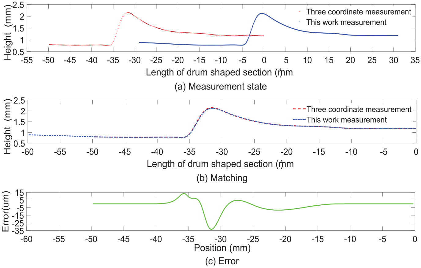
Comparison of circumferential shape detection in drum-shaped region.
The detection of the drum section shows that the drum phenomenon exists in the spinning process of the thin-walled cylinder. The drum section data collected by the two methods are matched by the ICP algorithm, and the detection accuracy of the method used in this article is about 0.05 mm based on the three-coordinate measurement data. The corresponding detection accuracy can meet the drum shape detection requirements during the spinning process.
The detection data of the thin-walled cylinder in the third spinning section were extracted by 1- and 10-s intervals, respectively, and the change trend of drum shape with spinning process was studied. The outer contour data of the extraction drum section are shown in Figure 14.

The profile curve of the longitudinal section of the drum-shaped region of each position.
It can be seen from Figure 14 that in the stable spinning of the thin-walled cylinder, the drum shape appearing on the front side of the spinning wheel does not change significantly in a short time interval and is basically maintained in one shape. Observing the drum curves at a longer interval, it was found that the height of the drum curve increased significantly with the progress of the spinning, which was basically consistent with the phenomenon observed in the numerical simulation (Figure 15). The change of drum shape will cause the change of stiffness and stability of drum region, which will affect the stability of spinning process.
Changes in the axial displacement of a drum-shaped rotating wheel.
Detection of abrupt change in spinning process based on drum shape similarity
It is known from the characteristics of the thin-walled cylinder spinning that during the stable spinning process, the drum curve changes less at adjacent moments and its shape has a high similarity and under the unstable spinning state, the drum curve changes turbulently and the shape similarity is low. In order to test the feasibility of drum similarity detection in judging the sudden change of spinning process, the DTW algorithm was used to analyze the drum data at the adjacent time of stability and instability. The DTW algorithm analysis of drum data at adjacent time in two states is shown in Figures 16–19.

The similarity of the two drum contours at adjacent moments in stable spinning process.

Matching accuracy of two drum profile curves at adjacent time in stable spinning process.
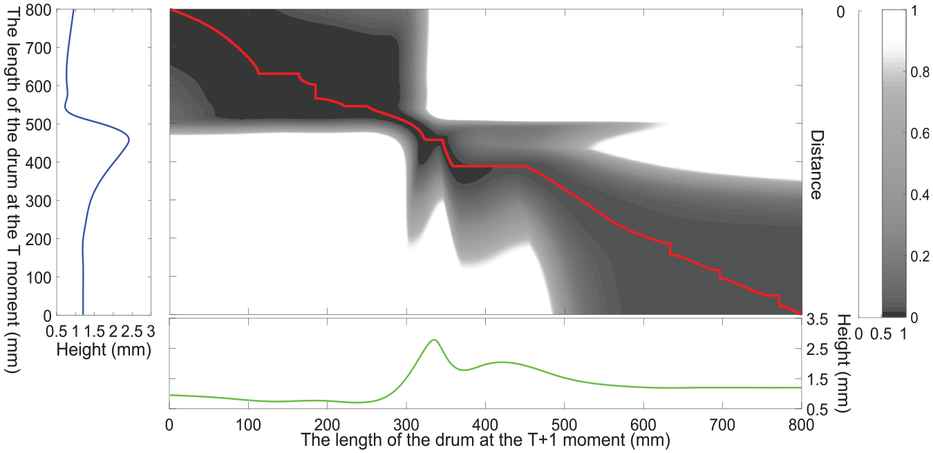
The similarity of the two drum contours at adjacent moments in unstable spinning process.

Matching accuracy of two drum profile curves at adjacent time in unstable spinning process: (a) original data, (b) warped data, and (c) error.
In the process of stable spinning of thin-walled cylinder, the shape of drum changes little at the adjacent time. The drum curve at the adjacent time is analyzed by the DTW, and the distance error of similarity points is within ±0.025 mm, and the total ED of two drum curves is 0.13 mm. The optimal distance path calculated is approximately straight line. The corresponding analysis data show that the similarity of the two drum curves at the adjacent time is high. The current spinning state inherits the previous one, and there is no sudden change in the spinning process within this short time interval. The continuous data acquisition of drum section in spinning process is carried out by linear laser displacement sensor, and the similarity of the drum curve at adjacent time is determined in real time; thus, the stability of spinning process is monitored.
As shown in Figures 17 and 18, when the spinning process becomes unstable from stability, the shape of the drum section changes greatly. The total ED of the drum curve at two times is 2.452 mm by the DTW analysis. The starting and ending lines of the distance path are far from the straight line, and the optimal distance path obtained by the matching becomes complicated, and the similar point corresponding distance error is about ±0.3 mm. The similarity of the drum shape at the time of the two spinning moments is poor, the spinning process is abrupt, and the current spinning pressure is unstable. In the spinning process, combined with the data collected continuously for the drum at the adjacent time, the similarity of the drum curve at the adjacent time is evaluated in real time, thereby realizing the monitoring of the spinning process based on the shape of the drum.
State determination of spinning process based on drum shape
Combining with the characteristics of spinning process, the curvature of drum curve, the number of bulge sections, and the height of drum are analyzed to realize the determination of the current spinning state. In order to make the spinning process of the ultra-thin wall cylinder unstable in a short time, a large reduction amount and a feed ratio are used for spinning, and the spinning is ended after the instability. The drum curves of the instability, the pre-stability, and the intermediate stable moment are extracted separately, and the curvature, the convex region, and the drum ratio are analyzed. The results of the analysis under the corresponding three states are shown in Figure 20.

Drum shape curve under different conditions: (a) stable state, (b) critical state, and (c) instability state.
Figure 19(a) shows the drum curve at the time of stable spinning, the curvature of the curve changes continuously, the whole section tends to be gentle, the curve of the drum section has an upward convex area, and the shape of the drum is skewed, conforming to G2 continuous; combining the maximum and minimum data of the drum region with the initial wall thickness, the drum ratio at the current moment is about 1.716, which is less than the critical drum ratio at stable spinning.
Figure 20(b) shows the results of drum curve analysis in the critical state. The curvature comb length of the curve of the drum section gradually changes in the peak position, and the curve reaches G1 continuous. At the same time, the curvature gradually becomes larger, and the radius of curvature gradually becomes smaller; slight wrinkles gradually appear along the peak of the drum shape, but the total number of bulges is always maintained at one. Combining the maximum and minimum data of drum curve with its initial wall thickness, the drum ratio at the current moment is 2.083, which is equivalent to the critical drum ratio mentioned above.
Figure 20(c) shows the results of drum curve analysis in the unstable state. The curvature comb length gradually changes greatly at the peak position, the curve can only reach G0 continuous, wrinkles begin to appear, and there are two upward bulges in the drum section. By extracting the maximum and minimum values of the height direction of the drum zone and combining the initial wall thickness, the drum ratio in the current instability state is about 3.390, which exceeds the critical value of the stable spinning pressure, indicating that the spinning process has been unstable.
Through the analysis of the drum shape in the spinning zone, the stability of the drum shape is judged by curvature comb and the number of bulge areas, and the state of the spinning process is further evaluated by combining the critical drum ratio. The monitoring of the spinning state based on the drum shape is achieved.
Conclusion
In this article, the linear laser displacement sensor is used to detect the drum curve during the spinning process of the thin-walled cylinder. The similarity analysis of the drum curve at the adjacent time and the analysis of the drum shape are used to realize the monitoring of the spinning state based on the shape of the drum. The following key conclusions are obtained:
The linear laser displacement sensor has the ability to acquire the local features of the detected body at the same time and can be used for the drum profile detection of the thin-walled cylinder spinning section. Based on the measured values of industrial coordinate-measuring machines, the accuracy of this method for measuring the drum shape is about 0.05 mm.
The shape change of the drum changes the spinning state, and the linear laser displacement sensor is used to continuously detect the outer contour shape of the drum at any time. The DTW algorithm is used to calculate the similarity between the current moment and the previous moment of the drum contour curve, so as to obtain the shortest cumulative ED value and the optimal path. The optimal path approximation straight line obtained by the DTW analysis is a similar evaluation criterion, which realizes the visual monitoring of the current spoilage state abrupt change.
The current drum shape reflects the state of the mode-locking ring, thereby embodying the state of the spinning process; the current spinning process state is judged by combining the curvature comb of the drum curve, the number of convex regions, and the drum shape analysis result. When the curvature comb of the drum curve changes uniformly, the curve is G1 continuous and the number of convex regions is 1. In this case, the spinning process is stable. When the curvature comb of the drum curve varies unevenly, the curve is G0 continuous and the number of bulge areas is more than 1. In this case, the drum curve is prone to axial folding and spinning instability. The above description realizes the spinning state determination based on the drum shape monitoring.
Future research
Based on the research of this article, the next step can be to study the optimization of process parameters in the spinning process as follows:
The multi-parameter spinning scheme will be formulated by the orthogonal experimental method. 41 At the same time, the parameter simulation based on MARC software and the spinning detection experiments under the corresponding parameters will be carried out, and the drum shape data in the simulation and experiment will be extracted and analyzed. Combining with the measured drum data, the three-dimensional model of the thin-walled cylinder under various parameters will be reconstructed by the implicit surface reconstruction algorithm. 42 The stress of the reconstructed model is analyzed by ANSYS software, and the critical value of drum stiffness in spinning process under various parameters will be obtained, which will provide a new evaluation index for the optimization of the process parameters. Combining simulation and spinning experiments, the study of the influence of the workpiece size, mandrel size, set clearance, wheel size, and process parameters (feed rate, reduction and speed, etc.) on the drum shape will be studied, which will provide a single factor rule for the optimization of the process parameters.
On the basis of the influence analysis of process parameters, aiming at reducing the height of drum, increasing the stiffness of drum and the stability of spinning process, and taking the feed rate, reduction, and rotational speed as variables, the multi-objective optimization algorithm based on genetic algorithm 43 can be used to establish the parameter optimization model and obtain optimal spinning process parameters through iterative calculation. Since the spinning process of the thin-walled cylinder is affected by various parameters, and there is still a relationship between the corresponding process parameters, the change of one parameter will inevitably affect the change of other parameters. For this reason, swarm intelligence algorithm (e.g. particle swarm optimization, ant colony optimization algorithm, and so on) can also be applied to the optimization of spinning process parameters by using Agirbas’ idea of applying swarm intelligence algorithm to conceptual design. 44
Footnotes
Authors’ contribution
X.W. is responsible for the experimental design and operation, the analysis and discussion of the experimental results, and the writing of the paper. J.-p.T. is responsible for the design and financial support of the experimental method. S.-q.L. participated in the experimental operation of this paper. X.-h.L. analyzed the spinning mechanism of the thin-walled cylinder and provided experimental venues.
Declaration of conflicting interests
The author(s) declared no potential conflicts of interest with respect to the research, authorship, and/or publication of this article.
Funding
The author(s) disclosed receipt of the following financial support for the research, authorship, and/or publication of this article: The current thesis was supported by the National Key Basic Research Special Foundation of China (2015CB057305).