
Abstract
Meso-scale numerical simulation of composite coupons is often defined using a ply-by-ply discretisation, where a large number of material properties are required to define the orthotropic elastic and failure behaviour of each ply. The interrelations observed between Tsai’s modulus and ply (intralaminar) material properties of several carbon-epoxy systems are used to devise a procedure that enables the fast estimation of meso-scale parameters. The predicted intralaminar strength and fracture toughness values are in good agreement with the experimental values. Furthermore, the utilisation of Tsai’s modulus paves the way for a unified approach, where a minimum set of experiments allows for estimating the material card required to achieve meso-scale simulations (e.g., open-hole tension) with good accuracy.
Keywords
Introduction
When the first philosopher, Thales of Miletus, posited,“All things are from water, and all things are resolved into water.”, 1 he pioneered a shift towards explaining the nature of matter through naturalistic-secular and rational arguments. 2 This shift laid the foundational groundwork for the development of both natural and applied sciences, influencing methodologies and perspectives that continue to shape scientific inquiry today.
While his theory about water is no longer valid, Thales’ approach to explaining one material property through the interrelationships of other material properties still resonates in the domain of engineering. This is particularly true for the characterisation of composite laminates, especially carbon fibre-reinforced plastics (CFRPs). CFRPs are comprised of different materials, carbon fibre and epoxy resin, to achieve a unified structure with a distinctive blend of properties, including a high strength-to-weight ratio, modulus-to-weight ratio, and exceptional corrosion resistance. This enables the design of lightweight structures, enhancing fuel efficiency and reducing emissions. 3 Consequently, they are becoming widely used in the aircraft industry. However, the mechanical characterisation and the generation of design allowables for CFRPs are challenging, expensive, and time-consuming, 4 which has been a recurring impediment for the cost-effective and fast characterisation and certification of composite aerospace structures. Therefore, there is an increasing interest in methods that rely on computational simulations to reduce the amount of experimental tests.
Finite element models (FEMs) are widely employed for computational simulations in the aircraft industry for design purposes. 5
Meso-scale models are typically employed to predict the progressive failure of coupons. They rely on ply-by-ply finite element models, where each ply is modelled as a homogeneous material with appropriate intralaminar constitutive laws, and delamination is predicted by cohesive elements in between.
Continuum damage models6–10 or smeared crack approaches5,11,12 have been developed to model the intralaminar behaviour. It should be noted that these models rely on a large number of properties, and acquiring these properties from experiments or through inverse calibration is challenging. These inputs comprise not only the elastic properties but also the strength values for different stress states (longitudinal tension and compression, transverse tension and compression, in-plane and out-of-plane shear) and toughness values (longitudinal and transverse tension and compression). Obtaining these values often includes extensive experimental investigations and complex data reduction techniques. 13 Consequently, exploring alternative approaches to compute material parameters without relying on a large amount of experiments or inverse calibration has become a crucial aspect of characterisation within the aircraft industry.
This issue is tackled in the present contribution by exploring the potential of invariant-based approaches to estimate material input parameters. The concept of invariance has proven useful in laminate design, as invariant properties remain unaffected by ply orientation, and because it is a quick way to make estimations with only a few experimentally determined properties. In the literature, Tsai and Pagano 14 presented stiffness transformation equations for ply rotation in a laminate based on invariants. Subsequently, Grédiac et al. 15 proposed a method for measuring invariants that describe the elastic response of anisotropic plates in bending.
More recently, Tsai and Melo
16
proposed a novel invariant-based approach to describe the stiffness of composite plies and laminates that uses the trace (or Tsai’s modulus, as renamed by Arteiro et al.
17
) of the plane stress stiffness matrix of a unidirectional ply,
The
This work is an extension of the concept developed by Tsai et al.16–20 over the past decade, extending the potential of the proposed invariant-based model (determination of laminae and laminates stiffness values) to include the estimation of intralaminar strength and longitudinal toughness parameters, which will further reduce experimental characterisation of CFRP laminae/laminate and enable the explanation of intralaminar toughness and strength parameters in terms of Tsai’s modulus. By reducing variables, this concept will simplify composite laminate design, analysis, and optimisation, resulting in lighter, stronger, and better parts. Additionally, reducing the number and type of tests for the characterisation of composite laminates will reduce the regulatory certification burdens (e.g., aerospace industry).
A new invariant-based model for predicting intralaminar strength and toughness
In this section, the proposed invariant-based (Tsai’s modulus-based) model is explained using quantitative (data-driven) analyses of intralaminar strength and toughness values in relation to the changes in Tsai’s modulus. CFRP materials were found to demonstrate common interrelationships with respect to their Tsai’s modulus,
This study defined its
Intralaminar strength and elastic modulus measurements of various CFRP laminae.
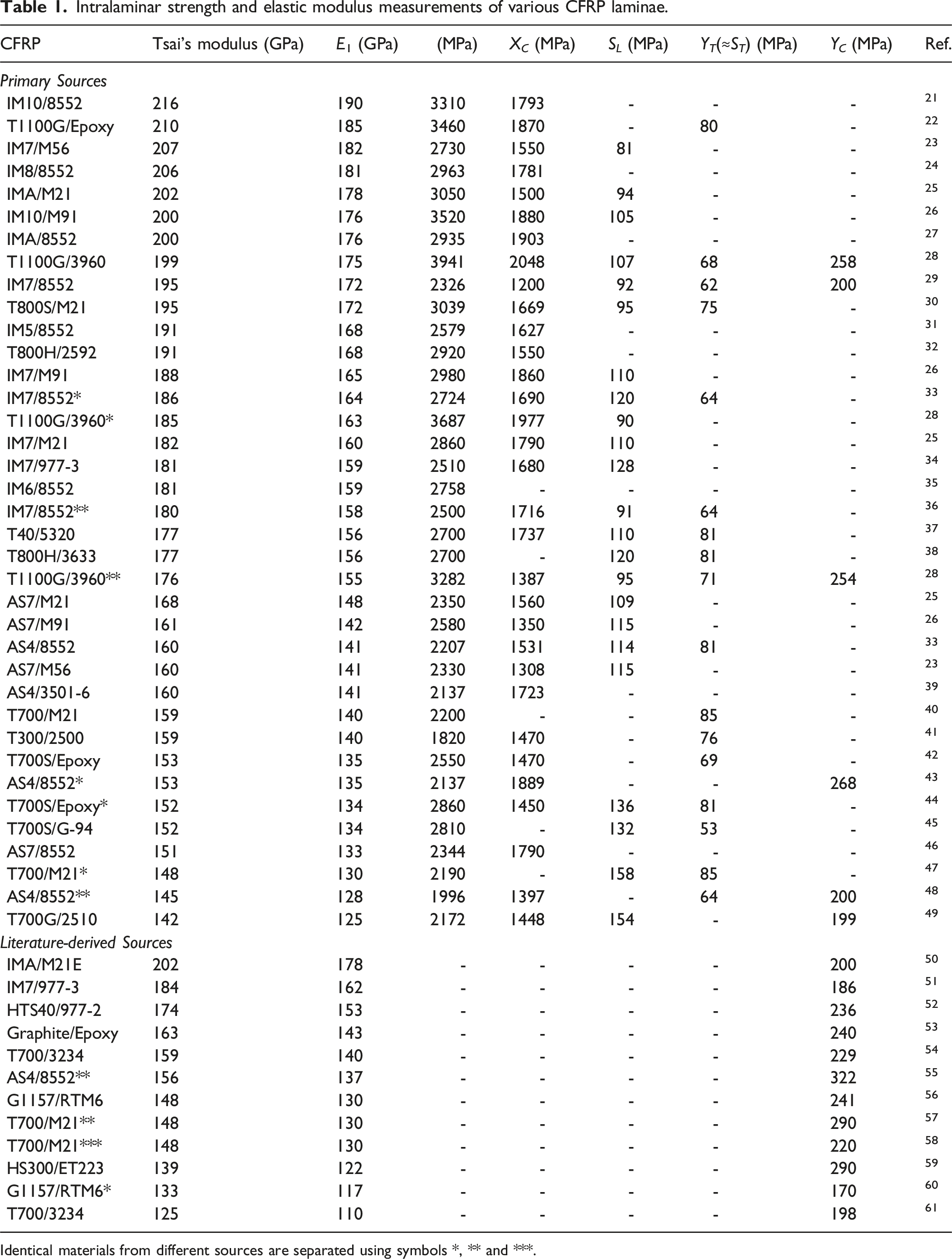
Identical materials from different sources are separated using symbols *, ** and ***.
Intralaminar longitudinal tensile fracture toughness, elastic moduli, and strength measurements of various CFRP materials.
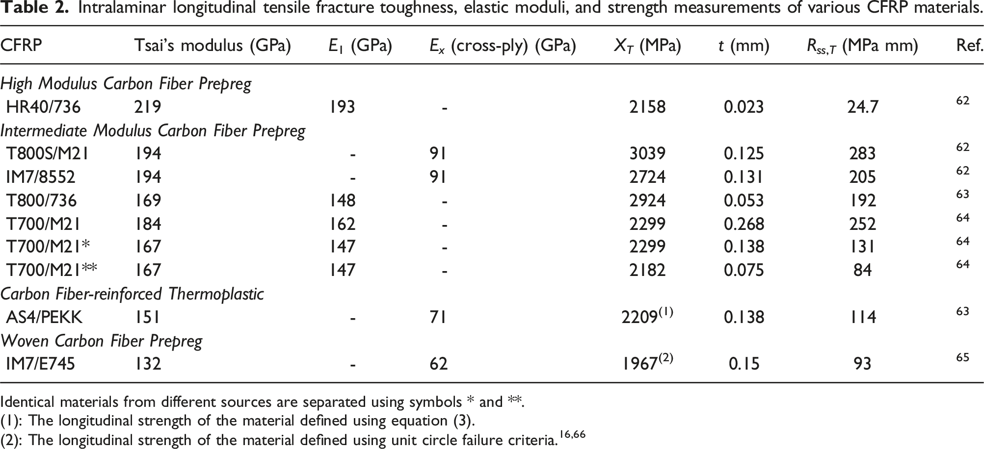
Identical materials from different sources are separated using symbols * and **.
(1): The longitudinal strength of the material defined using equation (3).
Fiber-dominated strengths
Using data-driven analyses, CFRP materials were found to share common longitudinal strength factors if the longitudinal tensile and compressive strengths are normalised by their respective Tsai’s modulus. The median values of these factors defined
In Figures 1(a) and (b), the relationship between tensile and compressive strength along the fibre direction (longitudinal direction) (X
T
and X
C
) with the respective Tsai’s modulus values are shown using the dataset provided in Table 1. Figures 1(a) and (b) show clear linear correlations between longitudinal strength and modulus values. Based on this relationship, the definition of Distribution and trends of longitudinal tensile (a) and compressive (b) strengths. Gaussian distribution and histogram of the 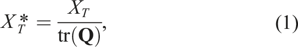
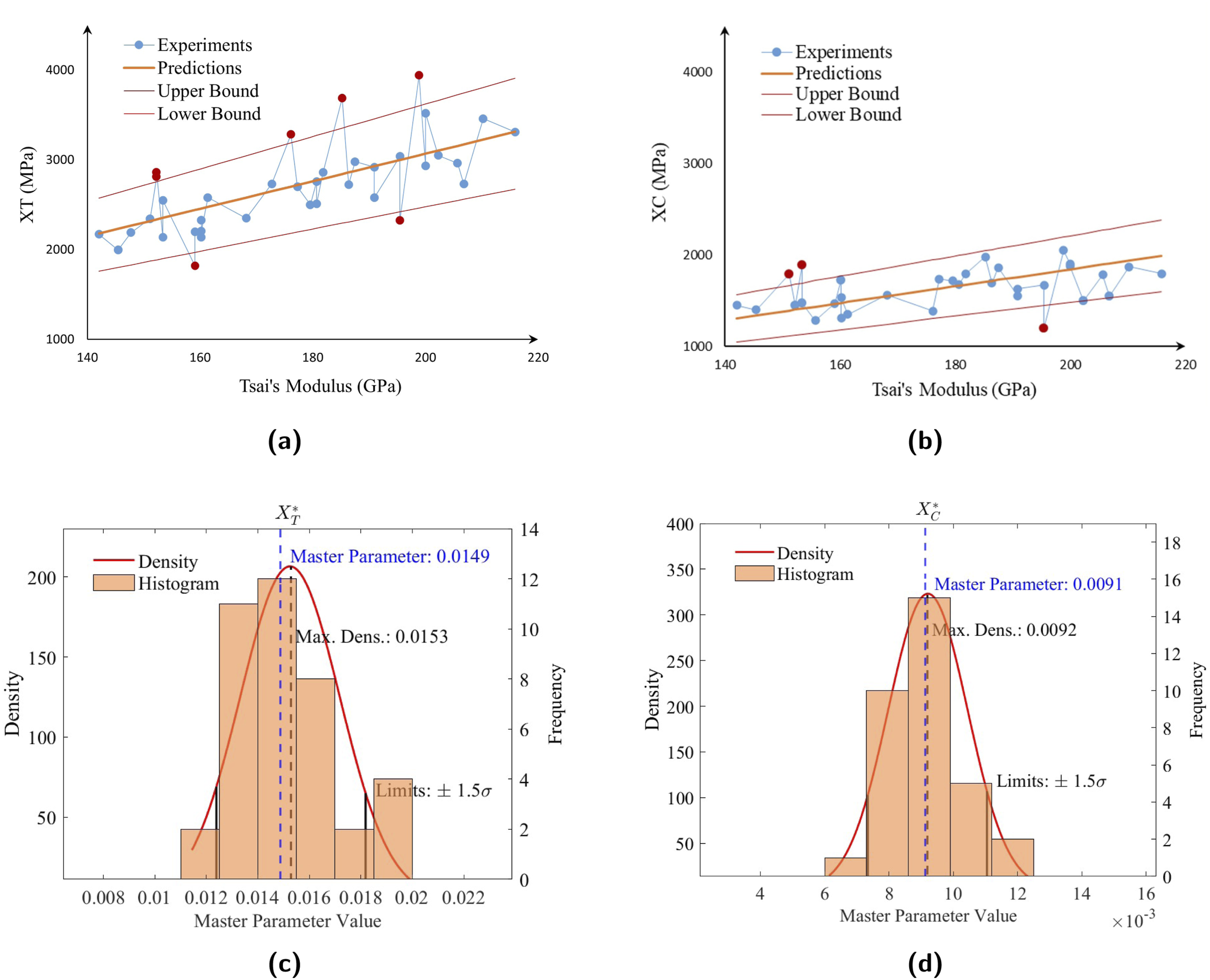
Additionally, Figures 1(a) and (b) show that some longitudinal strength values deviated from the general trend line. These outlier data points are either notably lower or higher compared to similar CFRPs with equivalent modulus values. To systematically identify these outliers, boundaries representing 1.5 times the standard deviation from the trend line were highlighted in Figures 1(a) and (b). Values outside these ranges (outliers) were highlighted in red and excluded from the calculation of
The histogram and the probability density functions corresponding to the defined 

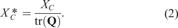
The defined Longitudinal tensile strength predictions were compared with the corresponding experimental measurements. Longitudinal compressive strength predictions were compared with the corresponding experimental measurements.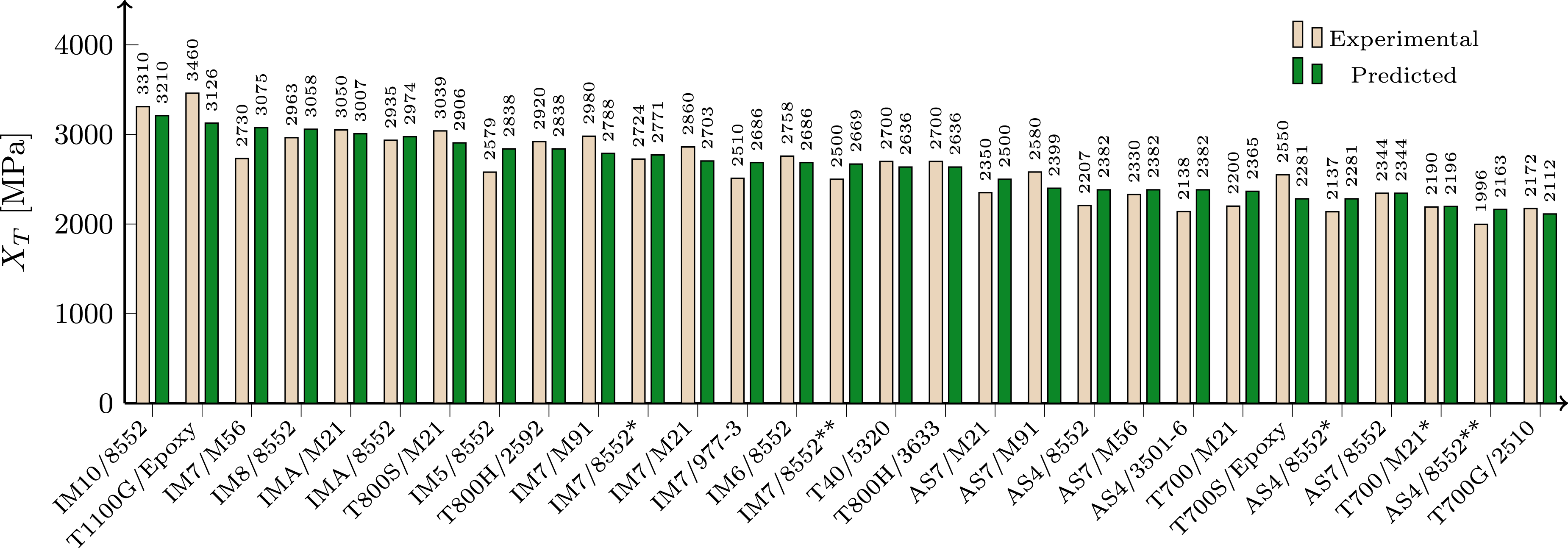
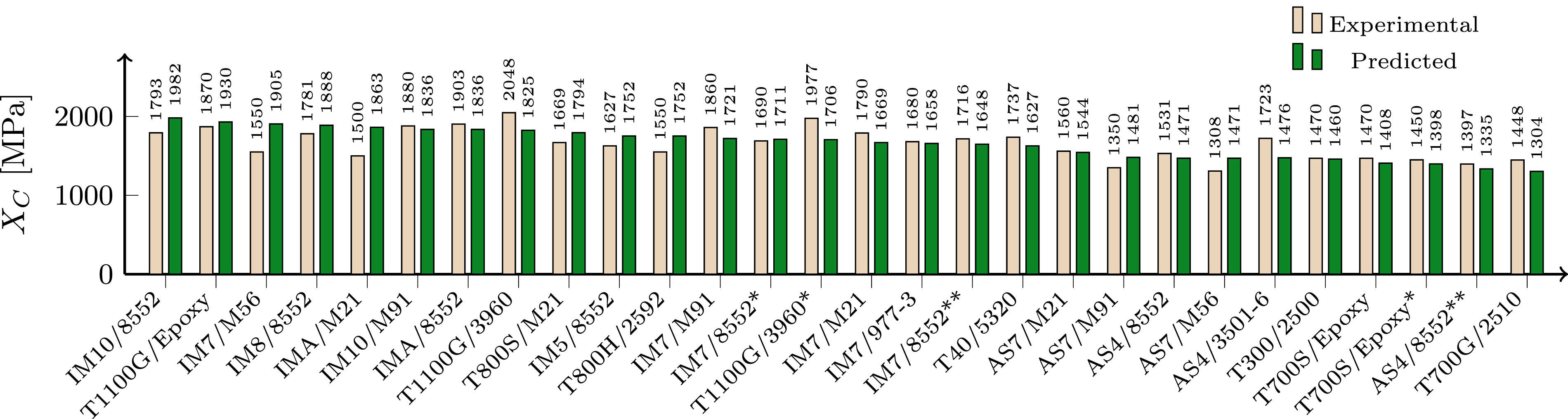
In Figure 3, the predicted compressive strength values have a 8.1% mean error with a CV of 9.5%, which is within the acceptable range in many engineering applications.
It was worth noting that the calculated longitudinal strengths can be used to determine the strength of laminates in the longitudinal direction of loading based on the relationship between stiffness (or engineering constants) and strength of the lamina/laminates, which can be derived using the
Matrix-dominated strengths
The matrix-dominated stiffness moduli contribute to the Tsai’s modulus of a CFRP lesser than the longitudinal elastic modulus of lamina/laminate.
16
However, the variations of matrix-related
For example, tests such as in-plane shear, due to fibre re-orientation (fibre scissoring), instead of the ultimate strength, the shear strength is approximated as the stress at the 5% strain displacement. Furthermore, multiple standards were proposed to observe more uniform in-plane shear stress concentration, where the ±45° in-plane (ASTM D3518 68 ), Iosipescu (ASTM D5379-12 69 ), and V-notched rail shear tests (ASTM D7078-12 70 ) are recognised as the most promising among the various ASTM shear test standards. 71 However, these three standards can yield different strength values. 71 Therefore, when creating the strength dataset in Table 1, the ±45° in-plane testing standard (ASTM D3518 68 ) was selected as the single preferred standard to maintain dataset consistency. Additionally, the ±45° in-plane test provides the largest dataset for data-driven analysis due to its widespread use in material characterisation (i.e., because of its straightforward testing procedure).
For the compilation of the transverse compression dataset, due to the scarcity of established experimental sources (e.g., HEXCEL, TORAY, and NIAR), the dataset included values from numerical studies that use the transverse compression of CFRPs. The literature-derived sources were separated from the experimental dataset − referred to as primary sources − in Table 1. Although this reduces the reliability of the data-driven analysis, it provides a general insight into the distribution of transverse compression values for CFRP materials. Consequently, no
During the out-of-plane shear, mode I failure is observed due to the stress transformation, leading to a similar failure mechanism as the transverse tensile stress. This similarity also allows their strength values to be comparable. Hence, out-of-plane strength and tensile strength are accepted as approximately equal in Table 1.
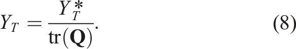
Regarding transverse tensile and in-plane shear strengths, the dataset in Table 1 reveals that they can be approximated as a function of Tsai’s modulus (c.f. Figure 4). Two different functions, (i) a linear approximation and (ii) an inverse relationship are fitted and their suitability is compared in Table 3, with their standard deviations, CVs, and error percentages. Both functions show acceptable accuracy, but the second function has the most accurate representation of the dataset (lower error). Furthermore, inverse relationship requires only one coefficient to be determined, whereas the linear function requires two. Hence, based on accuracy and simplicity, the function of type Distribution and trends of in-plane shear (a), transverse tensile (b), and mean transverse compressive (c) strengths. Gaussian distribution and histogram of the Comparison of different functions to approximate matrix dominated strength properties from Tsai’s modulus.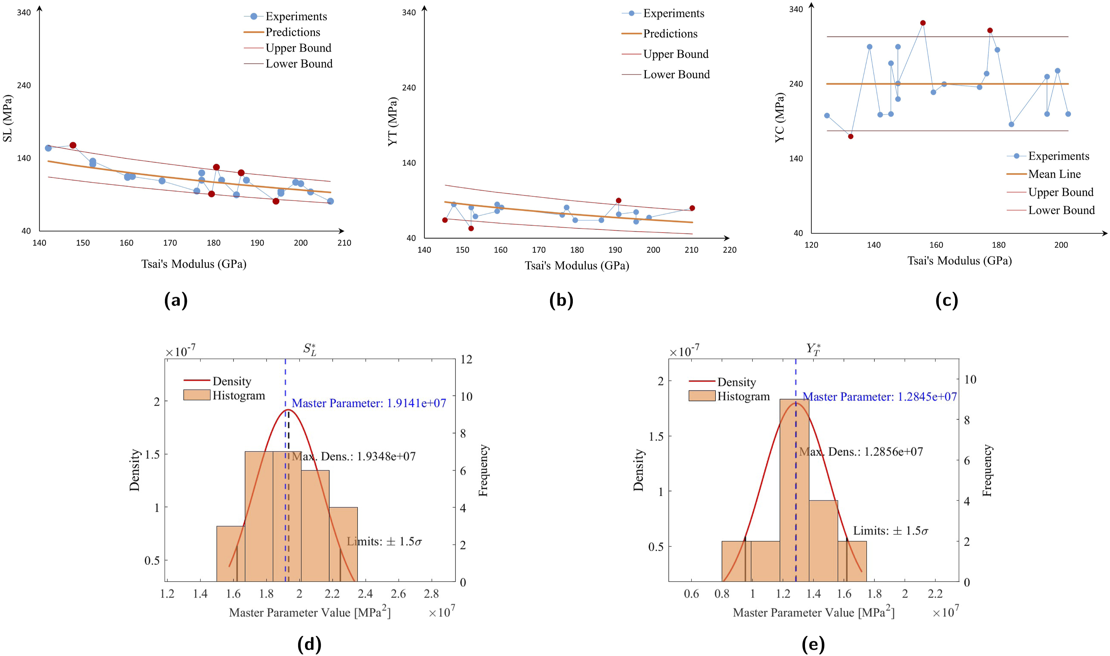
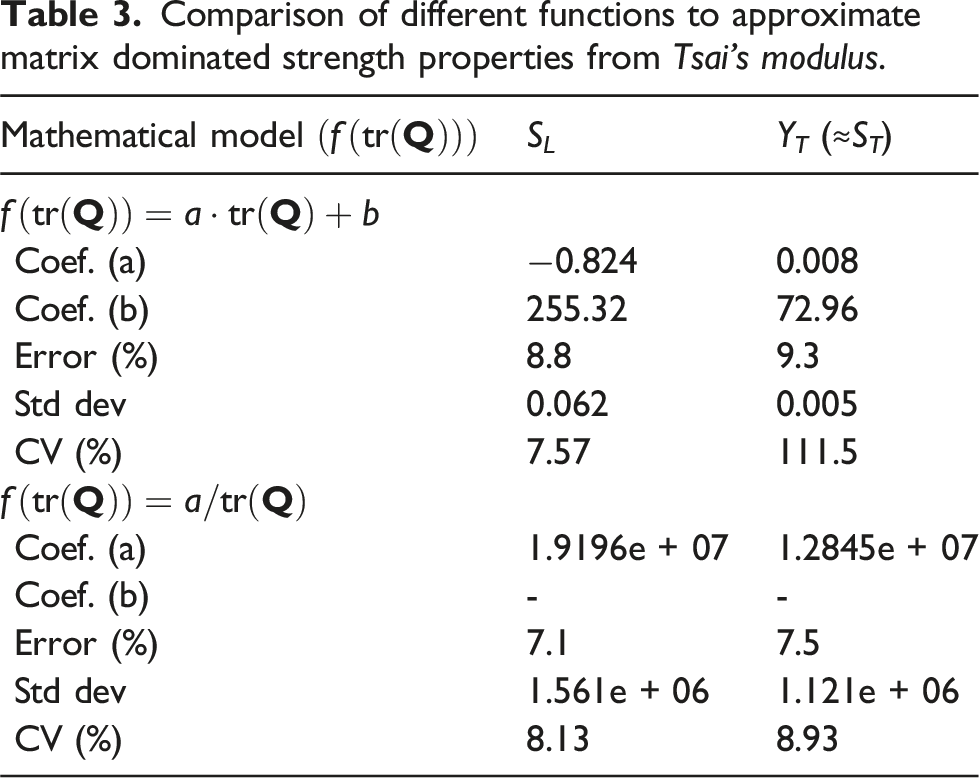
Figure 4(a)–(c) show the relation between in-plane shear, transverse tensile, and transverse compression (S
L
, Y
T
(≈S
T
), and Y
C
) and their corresponding Tsai’s modulus values, along with the aforementioned functions employed for the approximation. The 

Using the same method for finding outliers (as in Section 2.1), data points that are more than 1.5 times the standard deviation were marked in red and left out of the
In Figure 4(c), the experimental strengths are compared with the mean strength (i.e., 236 MPa) with a maximum deviation of 54 MPa and a CV of 14.1% which indicates a crucial need for additional experimental data. Expanding the dataset would enhance the model’s accuracy and reliability across a wider range of materials. Furthermore, more data would help minimise potential biases and ensure that the model remains accurate when applied to new materials.
Figures 4(d)–(e) display the histograms and probability density functions for the matrix-dominated 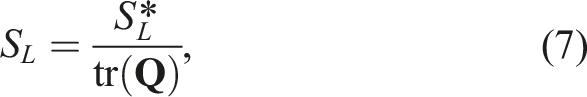
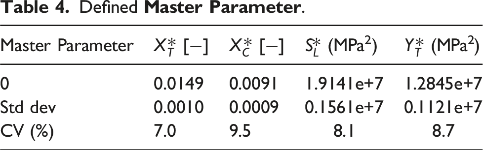
Defined
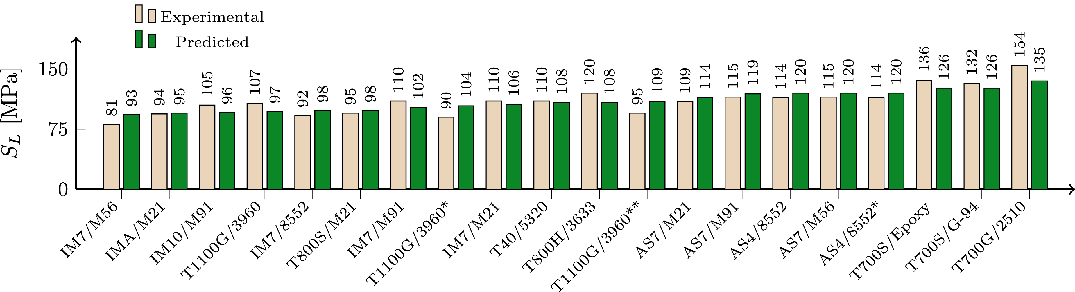
In-plane shear strength predictions are compared with the corresponding experimental measurements.
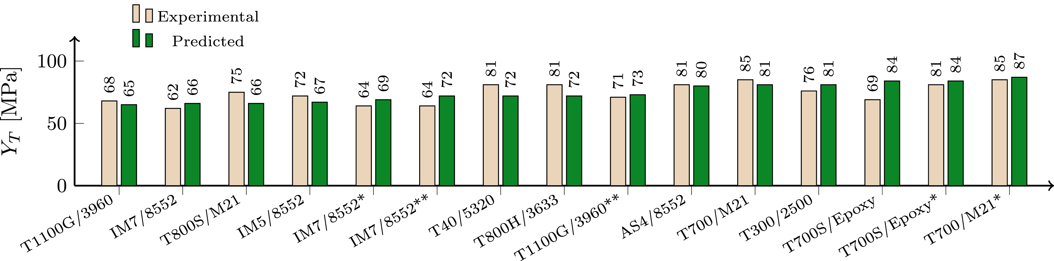
Transverse tensile strength predictions are compared with the corresponding experimental measurements.
In Figure 5, the 7.1% mean error with a maximum deviation of 18.9 MPa and CV of 8.1%, indicates that the in-plane shear strength predictions are generally reliable, especially given the complexity of modelling shear strength due to the intricacies of material behaviour. This level of accuracy further suggests that the model can be used in design and analysis.
In Figure 6, the 7.5% mean error with a maximum deviation of 15 MPa and CV of 8.7%, when estimating the transverse tensile strengths of composite materials, reflects the robust predictive capability of the invariant-based model.
Fiber-dominated toughness
The longitudinal intralaminar tensile fracture toughness does not have a standardised testing method. However, the double-edge notch tensile (DENT) test combined with the size-effect law, proposed by Catalanotti et al., 62 was used in industry (e.g., by AIRBUS) for material characterisation. 72 Therefore, data-driven analyses were conducted using experimental data obtained from DENT specimens. 73
Additionally, the measured apparent fracture toughness was reported as a function of the ply thickness.74,75 The study of Furtado et al.
64
found that effective tensile fracture toughness increases linearly with the ply thickness (due to thick plies observing split cracking in the vicinity of the notch, resulting in a stress redistribution that blunts the notch, leading to higher notched strengths). Thus, in the data-driven analysis for tensile fracture toughness, a reference ply thickness value (i.e., t
ref
= 0.135 mm) was defined for all materials, and their respective fracture toughness values were adjusted to this reference thickness in Figure 7(a). (a) Adjusted tensile intralaminar fracture toughness and linear trend. (b) Comparison of measured tensile intralaminar fracture toughness and predictions.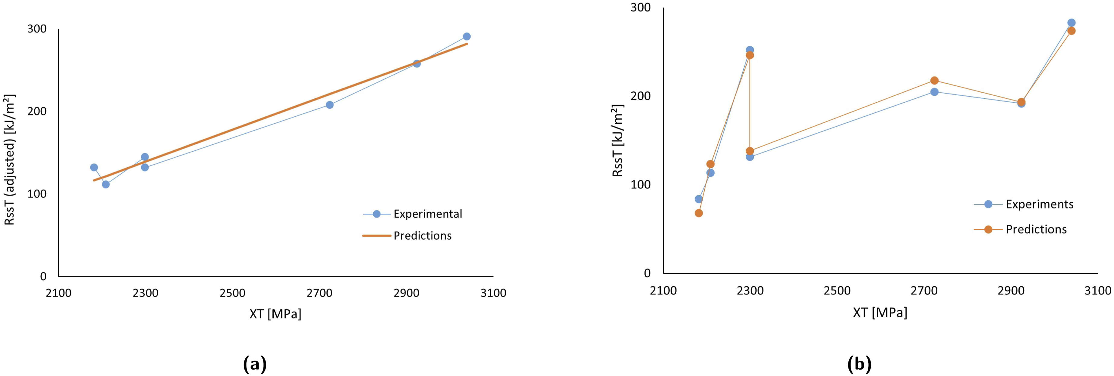
The adjusted tensile intralaminar fracture toughness values of the unidirectional, intermediate modulus CFRPs (see Table 2) with reference thicknesses exhibited a linear relationship with their respective longitudinal tensile strengths, as shown in Figure 7(a), which was formulated as:

A similar framework can also be applied to the compressive intralaminar fracture toughness. However, to implement this framework, the following shortcomings in the literature must be addressed: an adequate amount of experimental data for a data-driven understanding (e.g., Dalli et al. 73 proposed a more stable version of the double-edge notch compression (DENC) where the test fixture combined with combined loading compression (CLC), and only one experimental measurement was made for unidirectional CFRP using DENCLC by Danzi et al. 3 ), and the influence of thickness on compressive fracture toughness must be clarified.
Figure 8 shows a bar graph comparing experimental and predicted intralaminar tensile fracture toughness values using the experimentally measured longitudinal tensile strengths and the calculated longitudinal tensile strengths based on the Intralaminar tensile fracture toughness predictions are compared with the experimental measurements.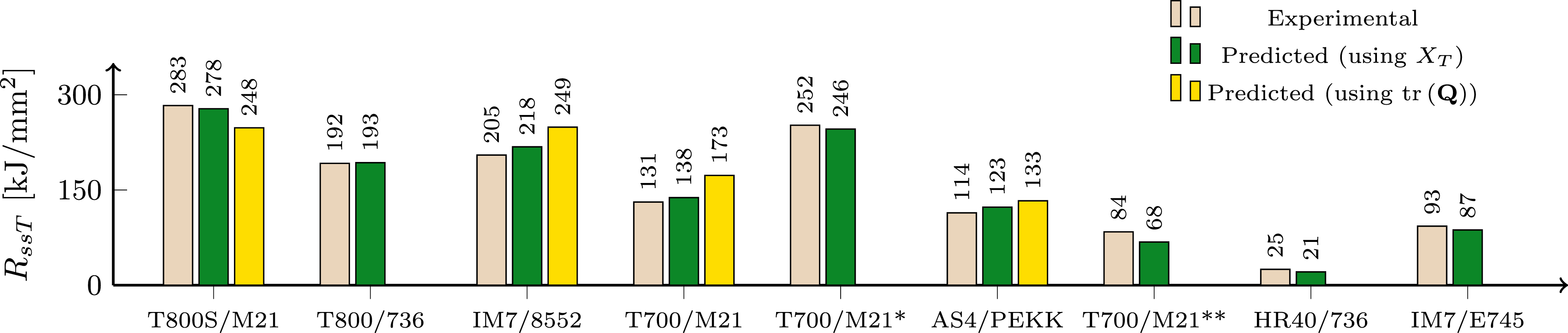
In Figure 8, an average error of 7%, with a maximum deviation of 10 kJ/mm2, indicates that the predicted tensile intralaminar fracture toughness values closely align with the experimental results when using the measured tensile strength values. Conversely, when using tensile strength values calculated based on
Assessment of the estimated material cards using finite element models
In this section, numerical simulations were performed to assess the accuracy of the invariant-based model in characterising intralaminar strengths and longitudinal tensile fracture toughness parameters.
A 2.5D (quasi-3D) infinitesimal continuum damage model (CDM) was used in this study to simulate the intralaminar degradation mechanisms of the composite ply. This constitutive model is based on the work of Maimí et al., 6 which developed a CDM for predicting the onset and evolution of intralaminar failure mechanisms and the collapse of composite laminates.
Physical capabilities of the continuum damage model.
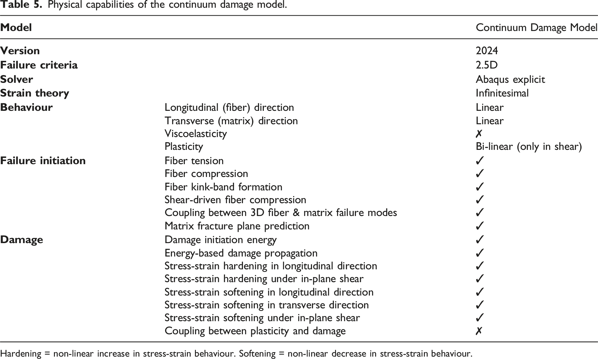
Hardening = non-linear increase in stress-strain behaviour. Softening = non-linear decrease in stress-strain behaviour.
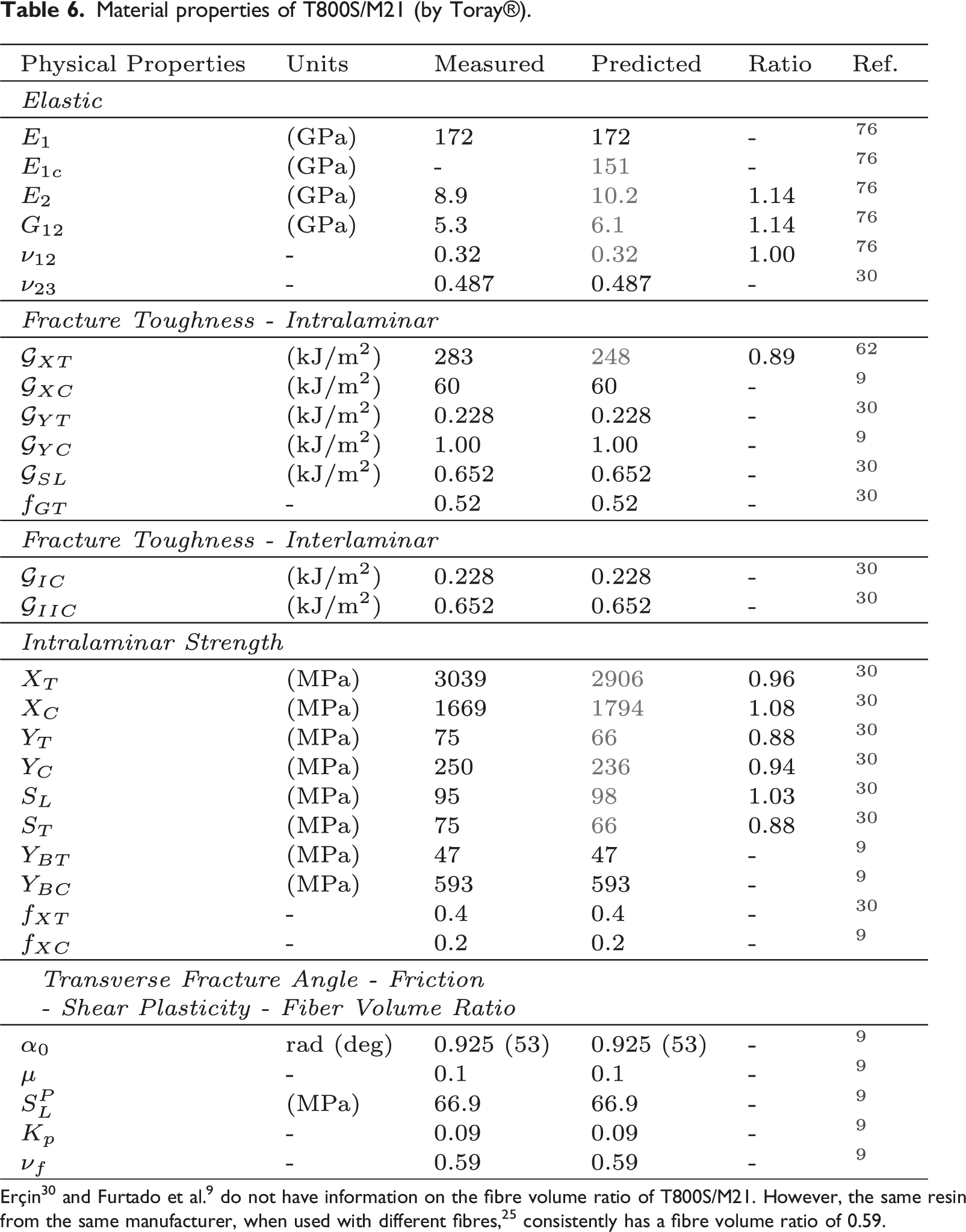
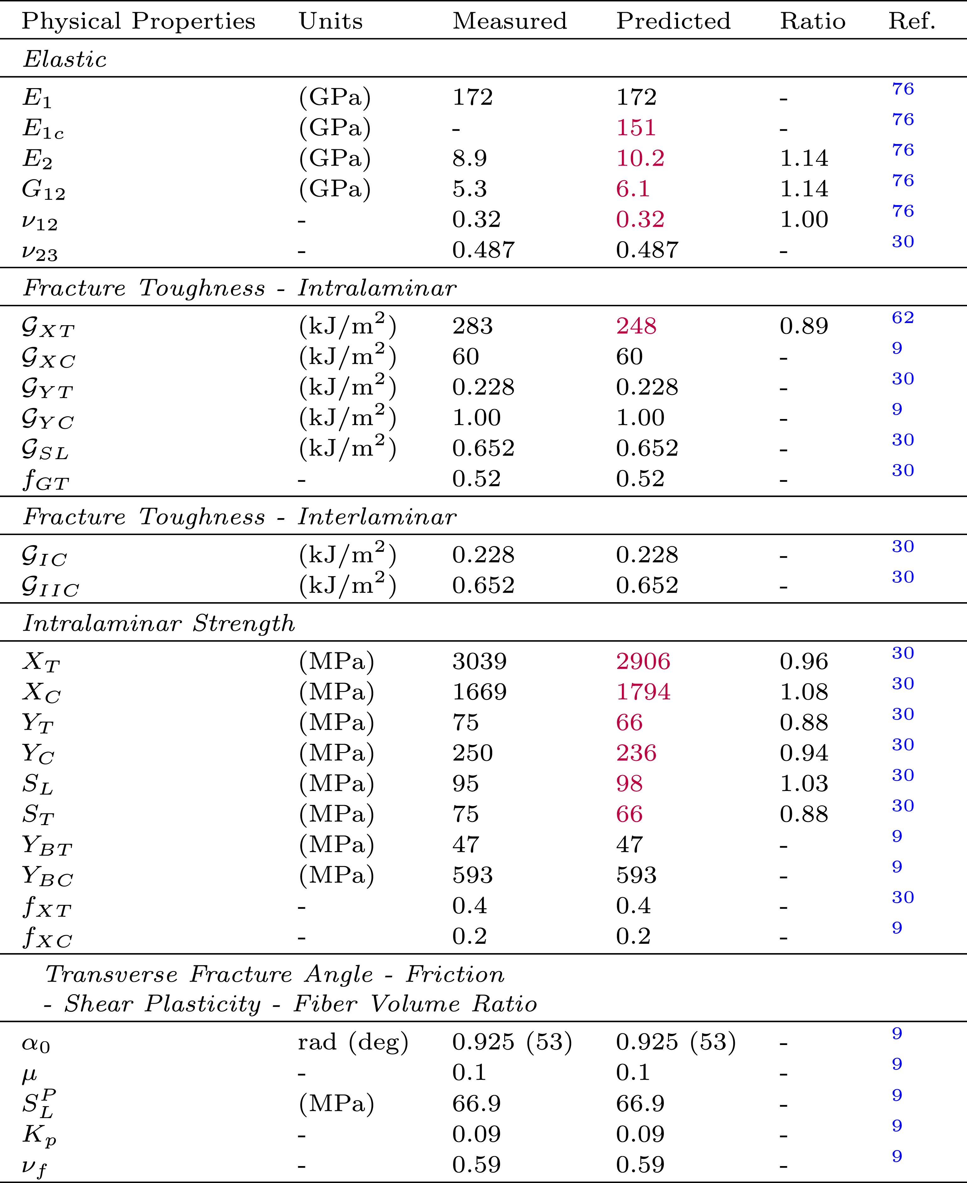
Material properties of T800S/M21 (by Toray®).
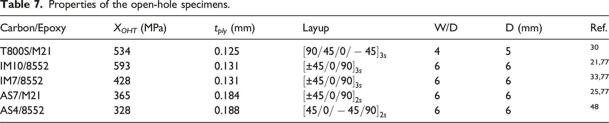
Properties of the open-hole specimens.
While choosing suitable validation materials, the following criteria were taken into consideration: the availability of data at hand and the representativeness of the full spectrum of intermediate modulus materials. T800S/M21 was chosen for validation because, based on the works of Furtado et al. 9 and Erçin, 30 the full material card and open-hole tension (OHT) characterisation had been conducted. Hence, initial numerical simulations were performed using material cards with fully measured intralaminar parameters and predicted counterparts, which would help to evaluate the general accuracy of the invariant-based model when compared to fully characterised intralaminar properties and provide a comparison for the predictions of open-hole tension strength. Furthermore, detailed information on open hole tensile tests and intralaminar longitudinal fracture toughness tests conducted for T800S/M21 (including the number of test specimens and standard deviation values) can be found in the works of Erçin et al. 30 and Catalanotti et al. 62
The four Hexcel® CFRPs were selected to cover the entire spectrum of intermediate modulus CFRPs. IM10/8552 and AS4/8552 represent the extremes of this range, as they have the highest and lowest longitudinal Young’s modulus values, respectively (as shown in Table 1), along with available open-hole tensile characterisation data. The other two CFRPs, IM7/8552 and AS7/M21, represent the middle of the spectrum, with IM7/8552 having slightly higher than average longitudinal Young’s modulus and AS7/M21 having slightly lower than average longitudinal Young’s modulus.
Furthermore, Hexcel® materials with −/8552 and −/M21 Fibre/Epoxy combinations were specifically chosen for this study, because of the availability of complete material cards for IM7/8552 and T800S/M21 in the source material 9 that allowed for accurate representation of interlaminar and other matrix-dominated properties in the numerical analysis by filling gaps in the material cards (highlighted in black) with values closely representing the actual properties. This approach ensured that the numerical simulations were conducted with the most reliable and representative material data available.
Figure 9 presents a comparison between the predicted intralaminar properties and fully measured experimental results for the open-hole tensile strength of a T800S/M21 quasi-isotropic laminate. It was observed that the error recorded for the fully measured material card is 0.5% overestimation, while the material card with predicted intralaminar strength values shows a 3.7% underestimation. Comparison of the numerical and experimental results for the open-hole tensile strength of T800S/M21.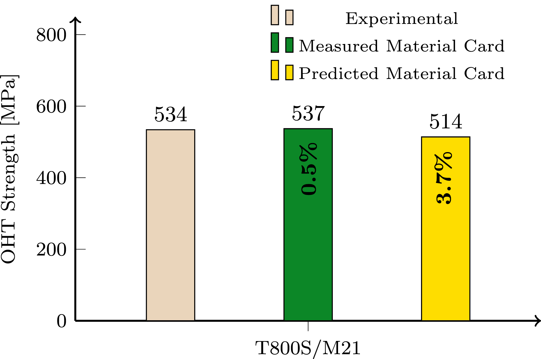
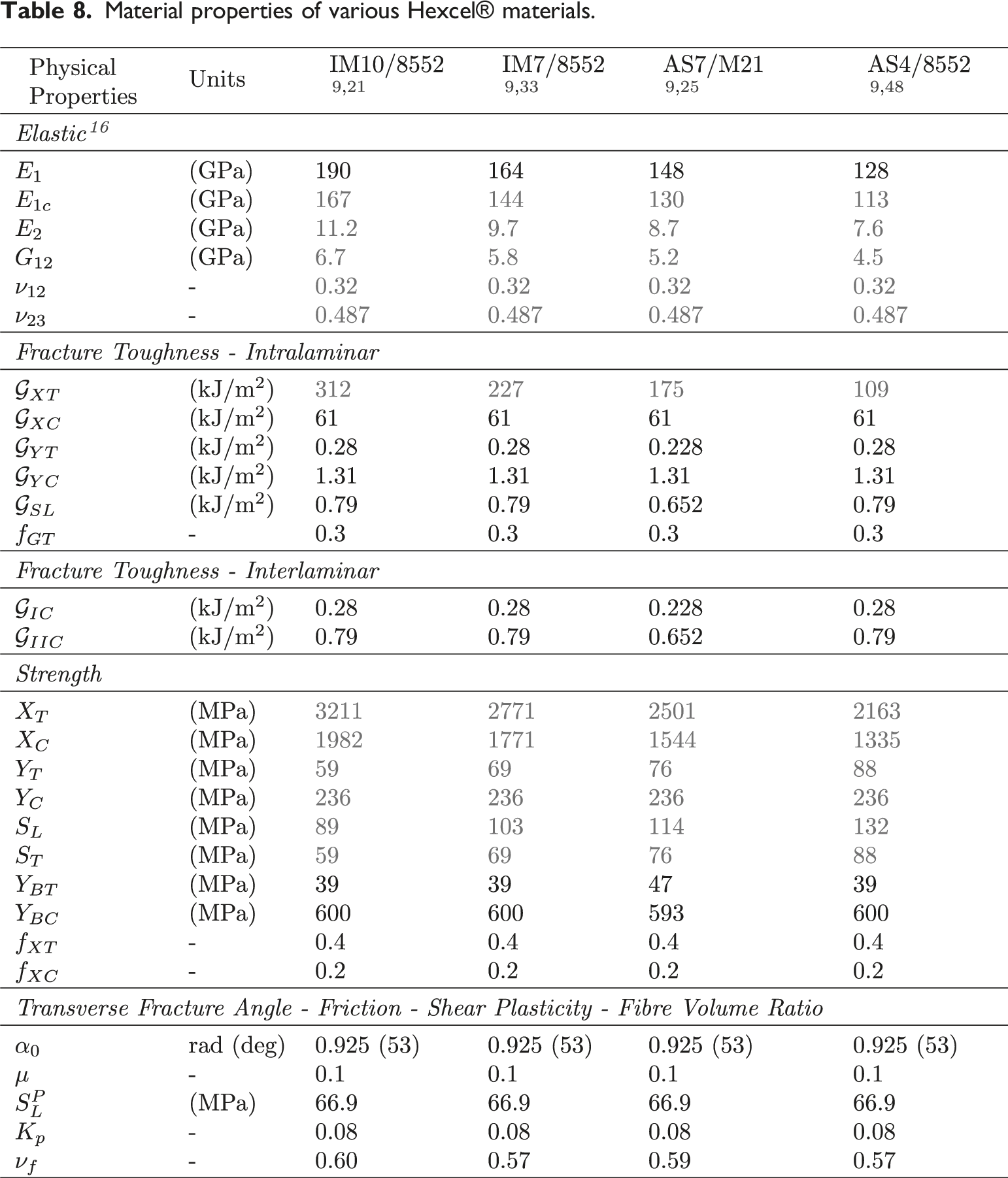
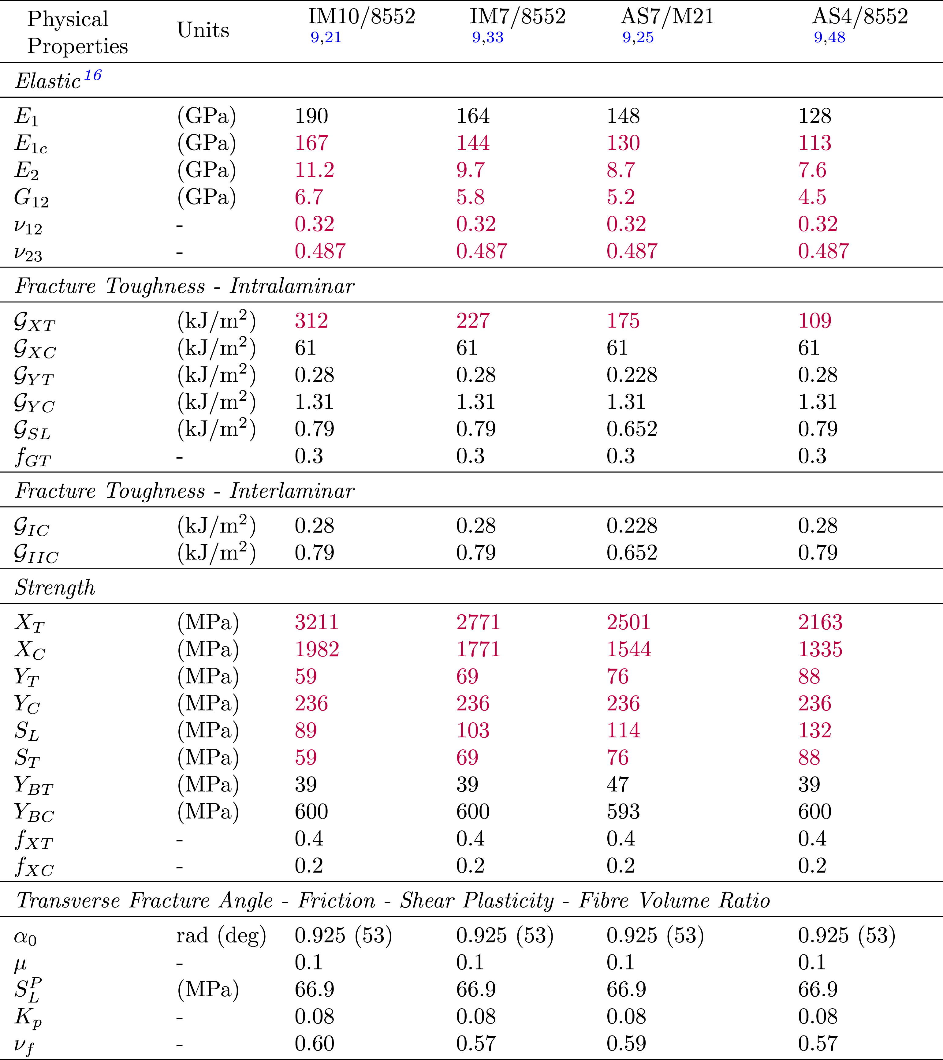
Figure 10 presents a comparison between the experimentally measured open-hole tensile strengths and the CDM predictions using material cards provided in Table 8 for four different CFRPs. The mean error recorded among the four CFRPs are 5.0%, with IM10/8552 showing a 7.0% underestimation, IM7/8552 showing an 8.9% overestimation, AS7/M21 showing a 3.5% overestimation, and AS4/8552 showing a 0.5% overestimation. Comparison of the numerical and experimental results for the open-hole tensile strengths of four CFRPs. Material properties of various Hexcel® materials.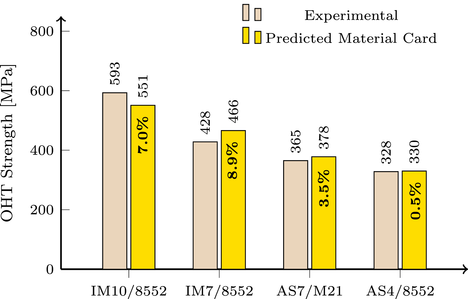
In conclusion, Figures 9 and 10 show that CDM predictions using material cards were based on
Conclusions
In this work, an invariant-based methodology was proposed to reduce the number of experimental tests required for the characterisation of the material properties of CFRPs, enabling running finite element analyses without using fully experimentally measured material cards. Through this methodology, intralaminar strength and fracture toughness properties were estimated from Tsai’s modulus which allowed the determination of intralaminar properties using only the longitudinal Young’s modulus of either lamina or laminate.
The proposed invariant-based model was initially validated by comparing the predicted intralaminar properties with their experimental counterparts. Then, the predicted parameters were used to fill in the intralaminar strength and toughness properties in the material cards for various materials, allowing them to be used in finite element analysis of open-hole CFRP specimens. This validation involved comparing experimental measurements with finite element predictions of the open-hole tensile strengths for T800S/M21 and four different CFRPs. The CDM predictions showed reasonable agreement with the experimental data.
A comparison between the experimentally measured material card for T800S/M21 and the predicted material card by the invariant-based model showed that the model accurately predicted intralaminar material properties and could complete missing information in material cards. Furthermore, the accurate results obtained for Hexcel® CFRPs in tension suggested that the invariant-based model was a viable tool for predicting material properties and can serve as a basis for further refinement and application in composite material analysis.
Consequently, the invariant-based model has the potential to significantly advance the aerospace industry by reducing the need for extensive experimental testing, streamlining the material characterisation process, and simplifying composite laminate design, analysis, and optimisation, which can lead to lighter, stronger, and more efficient components while enhancing the reliability of composite material predictions.
Footnotes
Acknowledgments
The authors are thankful to Prof. Albertino Arteiro for providing constructive feedback and insightful suggestions on the research methodology. Additionally, the authors are thankful to Prof. Albertino Arteiro for providing constructive feedback and insightful suggestions on the research methodology.
Declaration of conflicting interests
The author(s) declared no potential conflicts of interest with respect to the research, authorship, and/or publication of this article.
Funding
The author(s) disclosed receipt of the following financial support for the research, authorship, and/or publication of this article: The authors acknowledge the funding from the European Union's Horizon Europe research and innovation programme under grant agreement No. 101056682, through the project DIDEAROT - Digital Design strategies to certify and mAnufacture Robust cOmposite sTructures. Views and opinions expressed are however those of the authors only and do not necessarily reflect those of the European Union. Neither the European Union nor the granting authority can be held responsible for them.
Data Availability Statement
All the data employed in the current study is provided in the tables of this manuscript.