
Abstract
This study investigates the dynamic response of novel 3D natural fibre-reinforced hybrid composites. Two reinforcement techniques were employed: 2D intralaminar and 3D orthogonal-through-the-thickness (3D-OTT). Jute bidirectional fabric served as the primary fibre phase, while sisal and curauá fibres provided secondary reinforcement. The 3D-OTT architecture incorporated transverse fibres woven through-the-thickness of the fibre preforms, providing additional reinforcement. Pure jute composites (JFRP) were also tested for comparison. Low-velocity impact (LVI) tests, including perforation and repeated impact, assessed energy absorption, load-bearing capacity, and impact fatigue life. Results showed that 3D reinforcement effectively suppressed crack propagation during impact. 2D sisal fibre based architecture specimens demonstrated the highest absorbed energy and peak load during perforation due to fibre delamination, which created large energy-absorbing debonding areas. While CURAUÁ composites exhibited similar energy absorption and peak loads for both architectures due to strong fibre–matrix interlocking, SISAL composites showed lower energy absorption in the 3D configuration. Compared to a jute-based reference (JFRP), both CURAUÁ and SISAL composites demonstrated superior perforation resistance (30% and 50% increases, respectively). The 3D architecture significantly improved impact fatigue life, increasing it by 3.6× for sisal fibre and 2× for curauá based specimens. Micro-CT analysis revealed distinct crack- arrest mechanisms: 3D reinforcement reduced crack propagation in sisal fibre reinforced specimens, while curauá specimens benefitted from its strong fibre/matrix interface for natural crack arrest.
Introduction
In the quest for advanced materials that exhibit superior mechanical performance while decreasing overall environmental impact, natural fibre-reinforced composites (NFRCs) have emerged as a prominent candidate. Natural fibres, such as jute, flax, hemp and sisal, are extracted from renewable sources and their use in composites contributes to sustainability goals by reducing reliance on non-renewable synthetic fibres (e.g., by replacing synthetic composites in certain areas of application, reducing the structure’s carbon-footprint). This reduction is directly linked to the overall trend across multiple industrial sectors to reduce as much as possible the carbon-footprint of composite structures. 1 Furthermore, natural fibres are biodegradable which further reduces their environmental impact at end-of-life. When compared to their synthetic counterparts, natural fibres present lower cost as well as lower structural weight. Their specific strength and stiffness (i.e., relative to their weight) is high as well as their significant capacity to absorb vibration (damping). 2 However, the use of NFRCs is hindered by significant drawbacks such as moisture absorption, variability of fibre properties and the possibility of a weak interface with the resin matrix. 3 There are several techniques that can be applied to resolve some of these issues, such as, interlaminar hybridization with synthetic fabrics to reduce water uptake and chemical treatments to enhance fibre/matrix interface. 4
The automotive industry has been in the process of increasingly integrating NFRCs into vehicle structures due to their many attractive characteristics. 5 During the service of vehicular structural components, low-velocity impact (LVI) events are expected. In particular, front and side collisions are of great concern to the safety obligations of the automotive sector. 6 The most common low-velocity impacts are falling objects or a particularly severe hailstorm. It is noteworthy that in the world of low velocity impacts, it is not necessary for the surface of a composite material to be visibly damaged for a significant crack development to occur inside the structure. Barely visible impact damage (BVID) may already have created sufficient internal cracks to significantly reduce the lifespan of a composite material. 7 Moreover, it is known in the literature that the performance of NFRCs is not optimized for impact resistance and perforation energy absorption. Even at LVIs that are far below the perforation energy, through-the-thickness fibre failure is the most common damage mode for some natural fibre failures. 8 Therefore, the analysis of not only a single high energy complete perforation impact is necessary to ascertain the total energy a composite material may absorb, but also, lower energy repeated impacts are relevant to reach a more complete comprehension of the material damage evolution. Following an impact event, delamination-induced internal damage is very common in composite materials, leading to a reduction in material properties. 9 In order to surpass these drawbacks, 3D fibre architectures such as orthogonal through-the-thickness (OTT) reinforcements aim to enhance the transverse tensile strength, stiffness and delamination resistance of composite materials. 10 Traditional 2D composites, while offering excellent in-plane properties, often fall short in through-the-thickness performance and damage tolerance. 11
Many types of 3D fibre composite materials have been created, and they are classified according to the method by which the three-dimensional fibre reinforcement is produced. The most common types are 3D woven composites. 10 The fibre architecture is designed with a large percentage of in-plane continuous fibres (like a conventional laminate) to provide high in-plane mechanical properties. The novel architectural feature of 3D composites is the inclusion of high-stiffness, high-strength fibres in the through-thickness (or z) direction. The through-thickness fibres, which are given the general term z-binders, are used to provide 3D fibre composites with higher delamination fracture toughness and impact damage tolerance than conventional laminates. The volume fraction of z-binder reinforcement is usually low (typically under 5%–10%), although this is sufficient to greatly increase the delamination resistance and damage tolerance. 12 Various structural components, particularly in the aerospace industry, are equipped with fiber-reinforced composites manufactured by a 3D weaving process, for example, fan blades of airplane engines (manufactured by CFM International, France) and landing gear braces for the Boeing 787 (manufactured by Safran Landing Systems, France). 13 3D synthetic composites may also be used for radar absorbing capabilities in advanced weapons systems. 14 Finally, regarding 3D woven architectures, the transverse reinforcement may be orthogonal or angled, through-the-thickness or layer-to-layer interlocks. Woven OTT enhances mode I resistance while angled layer-to-layer (preferably at +-45°) enhances shear crack resistance (i.e., mode II). 15
The effect of 3D fibre architectures in composite impact performance enhancement has been analysed by various authors.16–19 Progress in the field of technical textiles and weaving technologies has allowed for the emergence of 3D woven textile composites as a substitute for 2D composites. 5 These distinctive features of through-the-thickness reinforcement has recently lead the automotive industry to utilize 3D woven composites. 20 More recently, the use of natural fibres in 3D reinforced composite materials is gaining attention due to their environmental benefits, cost-effectiveness, and satisfactory mechanical properties.21–28 For instance, Queiroz et al. 29 showed that by using a transverse fibre reinforcement phase (OTT), an improvement was observed in the single lap bonded joint performance of the composites. This was due to the likely significantly improved fracture toughness of the adherend. Despite the potential applications of 3D woven composites, significant limitations exist. It is expected that the in-plane properties will decrease when compared to non-crimp 2D fabric composites (perhaps as much as 20%). This crimp is the undulation that results from the interlacing of the multiple fibre fractions and directions. Moreover, the damage mechanisms are complex and involve damage within and between yarns and resin rich regions as well as voids and geometrical imperfections due to the manufacturing compaction process.
A key limitation of 3D composites compared to 2D counterparts is their higher fabrication complexity and associated cost, particularly at industrial scale where specialized looms are required. However, orthogonal through-the-thickness (OTT) architectures offer a favorable balance, being among the simplest 3D configurations to manufacture. Their lower architectural complexity reduces fibre crimp—thereby improving mechanical performance—and enables manual fabrication at smaller scales. 30 OTT structures also provide high transverse strength and fracture toughness, making them a cost-effective solution for both research and industrial applications. Low cost and efficient 3D woven composites have been explored in the literature and presented enhanced material properties. 31
Recently, Olhan et al. 5 performed an experimental investigation to evaluate the drop-weight low-velocity impact (LVI) and quasi-static compression-after-impact (CAI) characteristics of unidirectional (UD) laminates, along with 2D and 3D textile composites made from basalt, glass, and SISAL fibres using the VARTM technique. All specimens were subjected to three different impact energy levels 20 J, 30 J, and 40 J. The resulting contact force–time, force–displacement, and energy–time curves were recorded and analysed. They found that the 3D woven samples absorbed more energy compared to the UD and 2D specimens across all impact energy levels. However, additional mechanical characterization of these materials is necessary, as the field of three-dimensional fibre reinforcement in NFRCs is still in its early stages. To the knowledge of the authors, the analysis of perforation and repeated impact fatigue life of 3D fibre architectures in NFRCs has not been done in the literature to date. This paper explores the properties of 3D hybrid fibre-reinforced composites, focusing on their behaviour under two impact scenarios: full perforation and LVI repeated impacts. By examining factors such as fibre type, fibre/matrix interface quality and the three-dimensional arrangement of fibres, we aim to elucidate the mechanisms that contribute to enhanced impact resistance and impact fatigue life. Additionally, the study investigates the influence of hybridization on damage progression and energy dissipation during impact events.
Materials and methods
Materials
This research effort is part of an ongoing project of analysis of novel 3D reinforced NFRCs. The primary reinforcement phase consisted of pure jute fibre bidirectional fabrics, supplied by Sisalsul (São Paulo, Brazil), while curauá and sisal fibres were the secondary reinforcements for the 2D and 3D fibre preforms. The intralaminar reinforcement utilized a 2D configuration, where the secondary fibres were woven unidirectionally into a balanced 2 × 2 jute bidirectional fabric. Additionally, a tertiary fibre reinforcement was introduced in the through-the-thickness (transverse) direction, creating a 3D orthogonal through-thickness (OTT) fibre architecture for the NFRC preforms (see Figure 1). The curauá fibres used in this research were supplied by the Federal University of Pará, Brazil in-natura. The curauá fibres were washed to remove any dirt and debris then subsequently dried in an oven at 100°C until completely dry (controlled by weight). The sisal (APAEB 700/1, Bahia, Brazil) used were industrially made fibre rovings. For the 3D OTT preforms, the transverse reinforcement was woven through 5 layers of 2D intralaminar fabrics. A more detailed description of the fibre architecture reinforcement fabrication (for both 2D and 3D) can be found in a previous research.
29
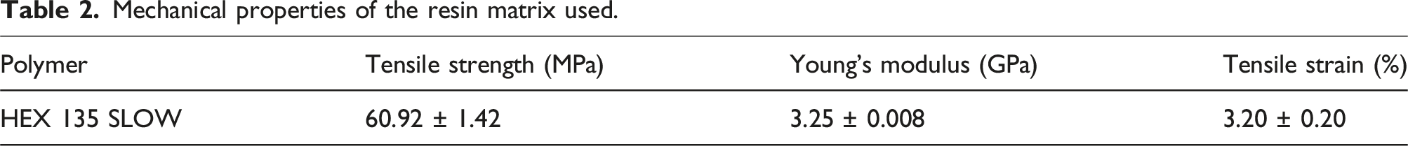
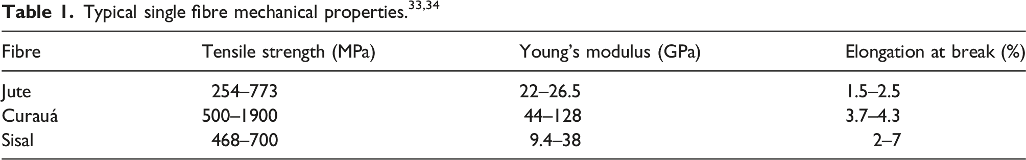
The mechanical properties of the fibres can be seen in Table 1. A bicomponent epoxy resin matrix, HEX 135 SLOW (Barracuda Advanced Composites, SP, Brazil), was used to fabricate the composite plates. The material properties of the resin matrix used can be seen in Table 2. Representative (a) SISAL 2D fabricated composite plate and idealized schematic, (b) SISAL 3D fabricated composite plate and idealized schematic.
32
Mechanical properties of the resin matrix used.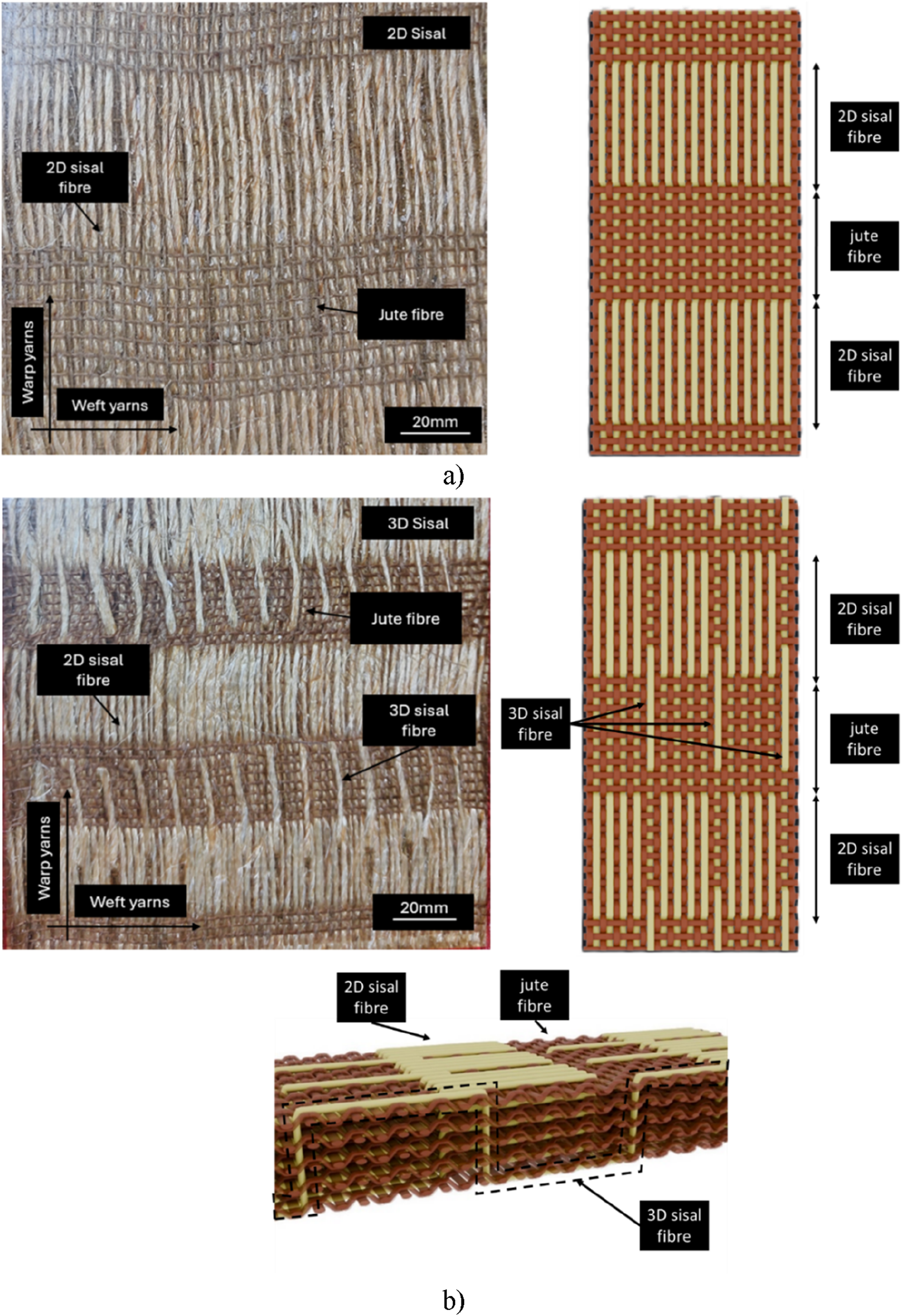
Specimen fabrication
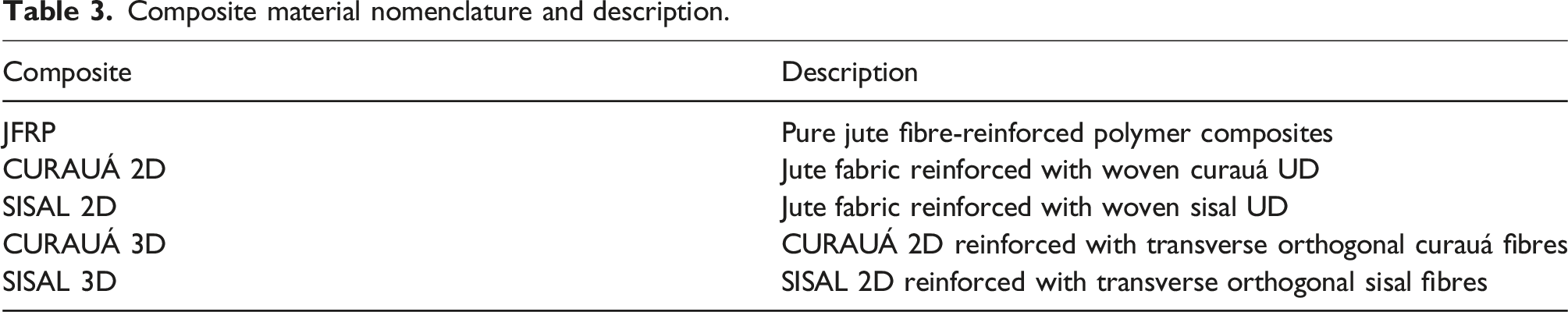
Composite material nomenclature and description.
Test methods
Impact tests
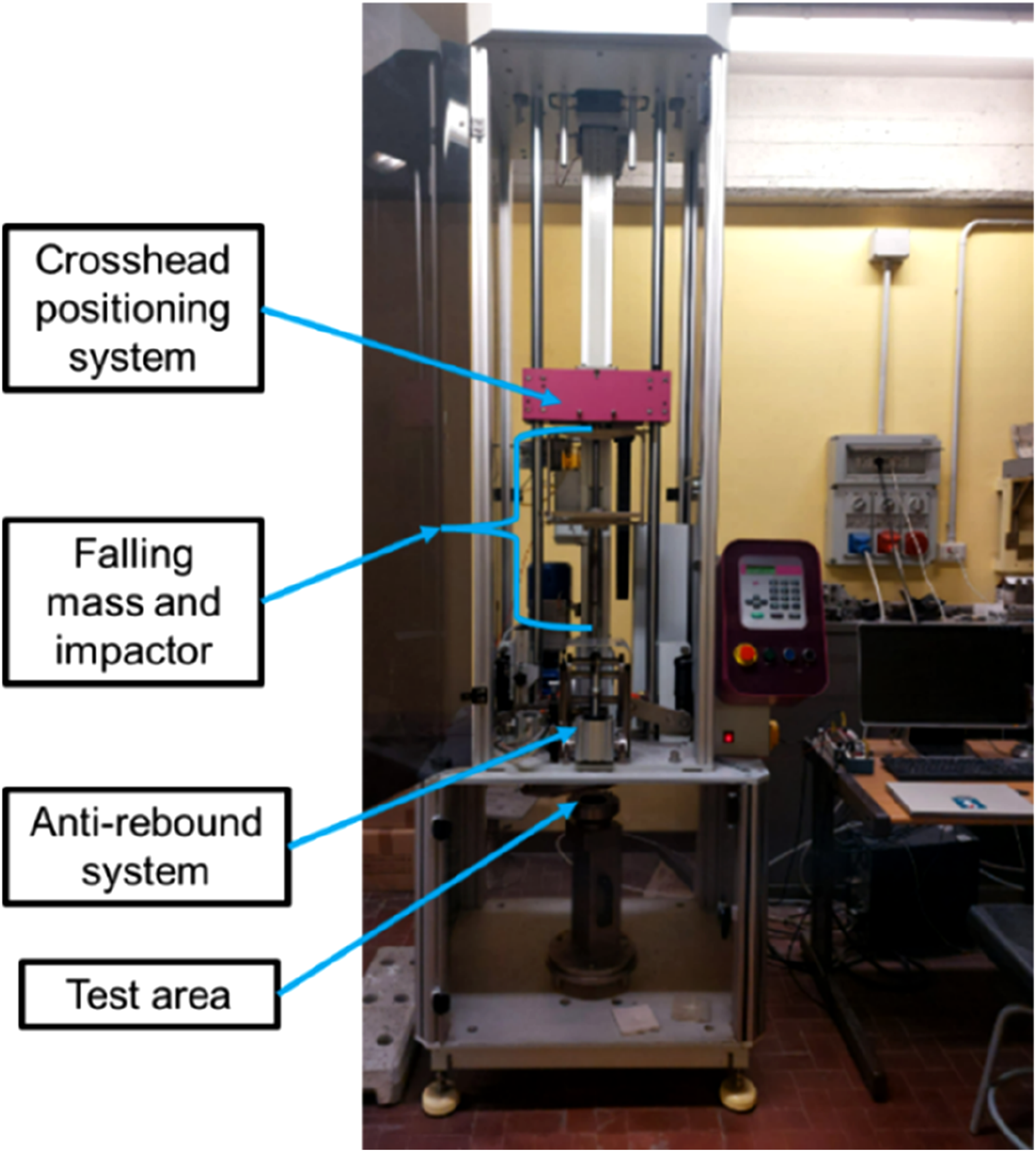
Impact tests were performed at Politecnico di Torino (Department of Mechanical and Aerospace Engineering, DIMEAS) on laminate specimens with dimensions of 100 mm × 100 mm, using a drop tower machine (Instron/CEAST Fractovis Plus) equipped with a hemispherical impactor instrumented with a piezoelectric load cell of 12.7 mm diameter at room temperature, see Figure 2. The samples were clamped between two steel plates with a circular opening of 40 mm diameter. The full perforation impact tests were done at an energy level of 45 J to ensure complete penetration of the dart. Force-displacement and energy-displacement curves were calculated for each test based on the data acquisition system. Three different energy levels were tested: 3 J, 7 J, and 12 J, respectively for the repeated impact of the different materials. This was chosen due to the different material impact response and therefore the required energies to reach failure in a feasible amount of time. The lowest energy level was used for the JFRP specimens, while 7 J was used for the CURAUÁ 2D and 3D specimens. The highest energy level was used for the SISAL hybrid composites, both 2D and 3D. This was done in order to reach failure in a reasonable time (i.e., at lower energy levels the hybrid SISAL composites did not present any visible damage after 200 impacts). A damage index (DI) was computed from the impact data. This index serves as a measure of damage propagation within the laminate as a function of test parameters (equation (1)).
35
LVI test set up.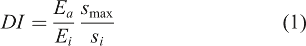
MicroCT analysis
X-ray computed tomography (CT) was performed using a custom-made CT system located in Politecnico di Torino J-Tech@PoliTO laboratory (Torino, Italy). The facility is equipped with a 300 kV X-ray source and a 5 μm minimum focal spot size, along with a flat panel detector featuring 2048 × 2048 pixels. The working distance between the source and the sample, as well as between the source and the detector, can be adjusted as needed
Results and discussion
Perforation tests
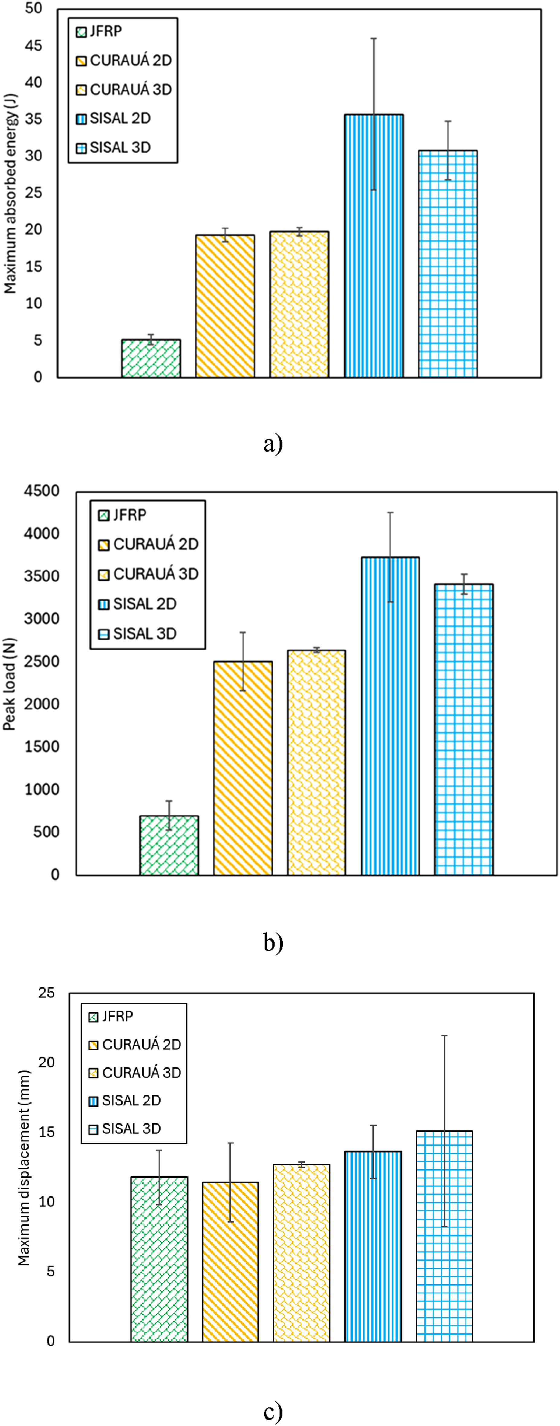
Figures 3 and 4 presents a summary of the results of the impact test campaign. The force-displacement representative curves can be seen in Figure 3(a) and from the initial slope of the curves (i.e., the elastic range), it can be seen how the stiffness varies as the damage propagates through the different materials at higher displacements. Impact test representative curves: (a) Force-displacement and (b) Energy-displacement. Statistical data for the perforation impact tests, (a) maximum absorbed energy, (b) peak load and (c) maximum displacement.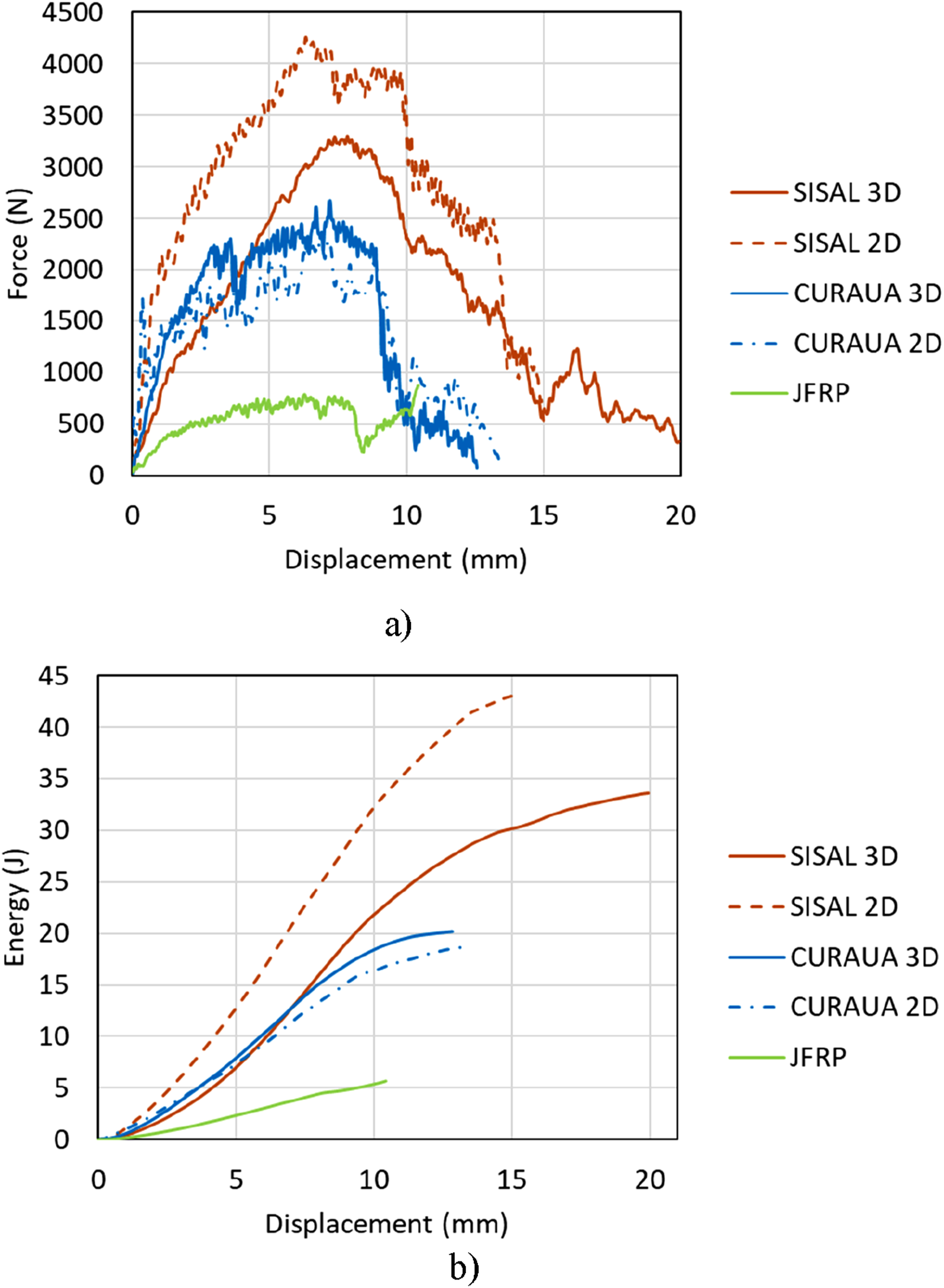
The change in slope at around 1 mm is due to initiation of damage such as matrix cracking. Later in the curves more significant slope changes as well as local oscillations are visible, indicating more severe damage such as delamination and fibre failures. Sudden drops in load are characteristic of fibre breakage of the surface layers. The trend for peak load observed is affected by the thickness, 36 however, all hybrid composites are comparable. It is also noteworthy that the peak load is reached for the CURAUÁ specimens and the SISAL 2D at approx. 6 mm and is maintained somewhat until approx. 10 mm (see Figure 3(a)). Similar behaviour has been previously reported for flax composites. 37 This interval was decreased for the SISAL 3D specimens to only approx. 1.2 mm. The JFRP barely presented a peak and absorbed very little energy due to its brittle failure mode (see Figure 9(a) and (b)). The hybridization technique, as well as the architecture had a significant effect in the peak load, the time at peak load, and the behaviour to complete perforation. From Figure 3(b) the energy-displacement representative curves for the perforation impact tests can be seen. The initial slope is linked to minor damage and deformation along the thickness direction caused by the transverse impact load. A cluster of initial slopes that are almost identical can be seen for the CURAUÁ 2D, 3D and SISAL 3D. However, higher deformation and damage can be seen for the SISAL 2D specimens. This trend continues until failure, and it is due to the damage progression within the laminates.
Figure 4 present the statistical data for the perforation tests. From Figure 4(a), it can be seen that all cases presented significant enhancements in the maximum absorbed energy (AE) when compared to the JFRP. For instance, the CURAUÁ specimens absorbed approx. 74% more energy, while the SISAL specimens approx. 86%. However, if normalized by thickness, the enhancements in AE are approx. 30% and 50% when the CURAUÁ and SISAL specimens are compared to the JFRP, respectively. This may be linked to the fact that the interfacial shear strength (IFSS) of curauá/epoxy is higher than sisal/epoxy 33 and in an impact scenario the chemical linkages between the fibre and matrix are broken and the fibres are separated from the matrix by parallel cracks. This occurs when the interface adhesion (IFSS) is weak, but the fibre is resistant. Given the creation of a debonding crack upon impact, a new fracture surface is created and this encourages a cascade of fresh surfaces creation upon many fibres debonding but resisting failure, increasing the overall absorbed energy.7,33 Further evidence of this can be seen in Section 3.4 (see Figure 10).
Regarding the effect of the fibre architecture in the AE of the hybrid composites, different trends were found. For the CURAUÁ specimens, no significant variation was observed from 2D to 3D specimens. This is linked to the inherent fibre morphology and crack-blunting mechanisms that will be discussed in further detail in the failure modes (section 3.3). Similarly, for the SISAL specimens, the AE tendency is also linked to the failure modes but in a different way. The SISAL 2D presented a slight enhancement in AE due to the higher tendency of crack nucleation and propagation throughout the specimen, while the resistant and ductile SISAL fibres managed to delay total specimen failure. Moreover, the relative similarity in energy absorption between 2D and 3D cases for the hybrid composites is also linked to the yarn densities being virtually identical since the z-binder fraction is so low. Dense yarn distributions play a pivotal role in stress propagation and concentration. 38 The SISAL specimens presented the highest overall absorbed energy of all tested specimens (i.e., approx. 36% and 45% more energy than the CURAUÁ for the 3D and 2D variants).
From Figure 4(b), it can be seen that all cases presented enhancements in the peak load when compared to the JFRP (i.e., improvements of approx. 73% and 80% for the CURAUÁ 3D and SISAL 3D specimens, respectively). Finally, no significant variations of displacement for perforation tests can be seen in Figure 4(c).
Repeated impacts
Figure 5 presents representative energy-displacement curves for the composites studied here under repeated impacts. For the JFRP specimens, all curves are presented (see Figure 5(a)), while for the hybrid specimens, due to the much higher number of impacts to failure, a different number of curves is presented (the number in the legend next to the name indicates the impact number). Energy-displacement curves for repeated impact tests, (a) JFRP, (b) CURAUÁ 2D, (c) CURAUÁ 3D, (d) SISAL 2D and (e) SISAL 3D.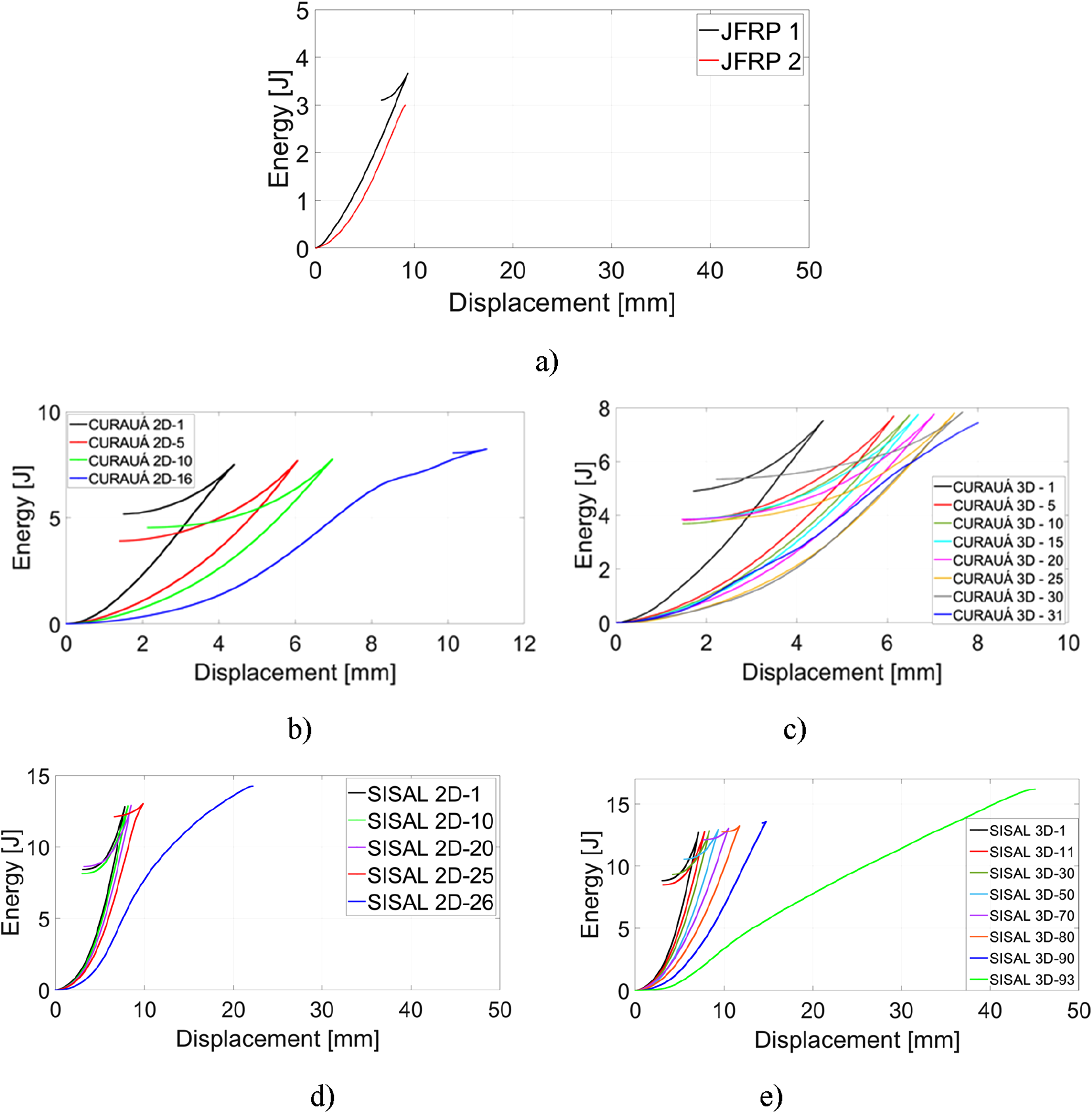
The elastic energy still stored within the specimen is depicted in the curves as a tail returning in the displacement (see Figure 5). Failure is defined as complete penetration. The 3D reinforcement significantly improved the resistance to repeated impacts for both CURAUÁ and SISAL specimens. Specifically, the CURAUÁ 3D presented almost 2× the number of impacts to failure, while the SISAL 3D presented almost a 4× increase when compared to their 2D counterparts. It can be seen from Figure 5(b) and (c) that the displacement increases much faster (i.e., at a lower number of impacts) for the CURAUÁ 2D when compared to the 3D. For example, at approx. 7 mm, the peak of the 10th impact is visible for the CURAUÁ 2D, while for the 3D the same displacement correlated to the peak of the 20th impact. This suggests that the transverse fibres are acting to restrain the displacement of the specimen via crack arrestment mechanisms (delaying and bridging the cracks).
10
Similarly for the SISAL specimens, the 10 mm displacement correlated to the peak of the 25th impact for the 2D specimens, while for the 3D, it correlates to the 70th (see Figure 5(d) and (e)). Upon failure, the energy absorbed increases significantly for all hybrid specimens, especially for the SISAL specimens, due to the total release of the elastic energy.
7
It is observed that the 3D hybrid composites presented a higher number of impacts needed to fail when compared to the 2D. This higher damage tolerance of 3D architectures has been previously reported, however, there is limited literature available on repeated impact response of 3D composites.
36
This damage tolerance stems from the enhanced resistance to delamination and transverse matrix cracking afforded by the 3D reinforcement which suppresses deformation in the out-of-plane direction and restricts delamination propagation (i.e., most common failure modes in laminated structures).
5
Figure 6 presents the representative load-displacement curves for all cases. All groups presented the expected trend of decreasing peak load and increasing displacement as a function of repeated impacts.
35
A significant variation in the slope of the curve from the first impact to the second is visible for all cases, with the exception of the SISAL specimens, likely due to the ability of the transverse fibres to maintain the integrity of the specimen at a relatively low energy level (12J). It is known that the behaviour of the curve is associated with the damage progressions within the specimen (matrix cracking, fibre failures).
7
It is possible to observe that for neat specimens (i.e., JFRP), the first impact already presented significant damage propagation evidenced by the jitter in the curve following the initial slope (see Figure 6(a)). For the JFRP, only one more impact failed the specimens at 3 J. This is due to the inherently brittle nature of both reinforcement phases (i.e., matrix and jute fibre), as well as the fact that due to the nature of the jute fabric, large resin rich zones exist in the spaces formed by the warp-weft weave. A similar trend can be seen for the CURAUÁ specimens, where the first impact presented more apparent significant damage than the following (see Figure 6(b) and (c)). The SISAL specimens, both 2D and 3D, break this trend since the initial curve and the following are much smoother and present much less accumulated internal damage per impact than the other specimens. For the SISAL 2D, a more significant jitter in the curve is visible from the 25th impact (one before last), while for the 3D this becomes more apparent from the 70th impact (see Figure 6(d) and (e)). Force-displacement curves for repeated impact tests, (a) JFRP, (b) CURAUÁ 2D, (c) CURAUÁ 3D, (d) SISAL 2D and (e) SISAL 3D.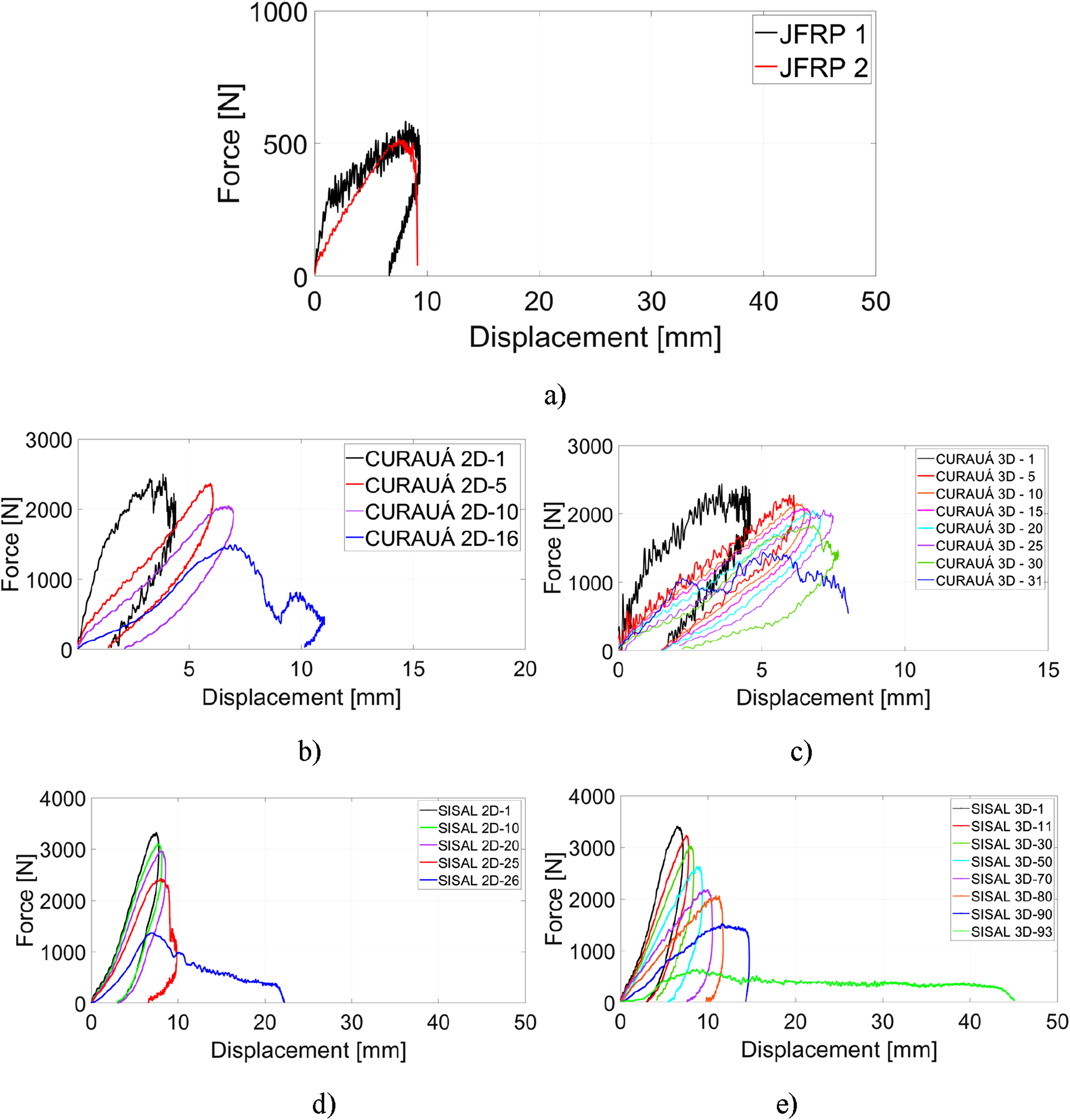
This is evidence of how the secondary fibre phase’s material properties affect the composite. The higher ductility and strength of both curauá and sisal (see Table 1), completely change the material response to impact fatigue in both 2D and 3D variants.
In order to put these values in perspective, the trends observed in the current research may be compared to that of Sozen et al.
39
The researchers evaluated the impact fatigue performance of CFRP, GFRP and a hybrid of both. The composites were fabricated with 13 layers of reinforcement and the hybrid presented a [G/C]s stacking sequence. It was found that for an impact energy of 25.2 J, the carbon, glass and hybrid composites presented 9, 43 and 13 impacts until failure, respectively. Therefore, the GFRP presented an enhancement of 5× compared to the CFRP due to its higher ductility. The SISAL 3D specimens in this research presented 93 impacts to failure at 12 J. Therefore, an approx. 2.2× increase in impact fatigue life compared to the GFRP in
39
at half the impact energy. Assuming linearity, the impact fatigue lives would match at double the energy level (i.e., 25 J). The assumption of a linear material property decrease until failure is supported by the trends observed for the SISAL 3D in Figure 7. Therefore, the trends suggest that the SISAL 3D is at a similar energy absorption level performance of a 13-layer GFRP, while being made of only 5 layers of natural fibre composite. A significant decrease in cost and environmental impact, while maintaining the LVI fatigue performance. Similarly, when compared to the trends reported by Olhan et al.,
5
the SISAL 3D specimens presented similar peak load and AE to their G3D40 case (i.e., 3D woven GFRP at 40 J perforation impact). This demonstrates the capacity of this family of NFRCs to replace GFRP in select applications. Another possible immediate industrial application concerns the recent semi-structural automotive uses of amplitex® flax fibre composites by BComp®.
40
The SISAL 3D composite presents similar in-plane mechanical properties (e.g., amplitex® 5031) while boasting a significant impact fatigue life enhancement, a crucial design parameter for automotive panels exposed to the elements, all while lowering costs. Material impact parameters as a function of repeated impacts: (a) absorbed energy, (b) peak load, (c) displacement, (d) bending stiffness and (e) damage index.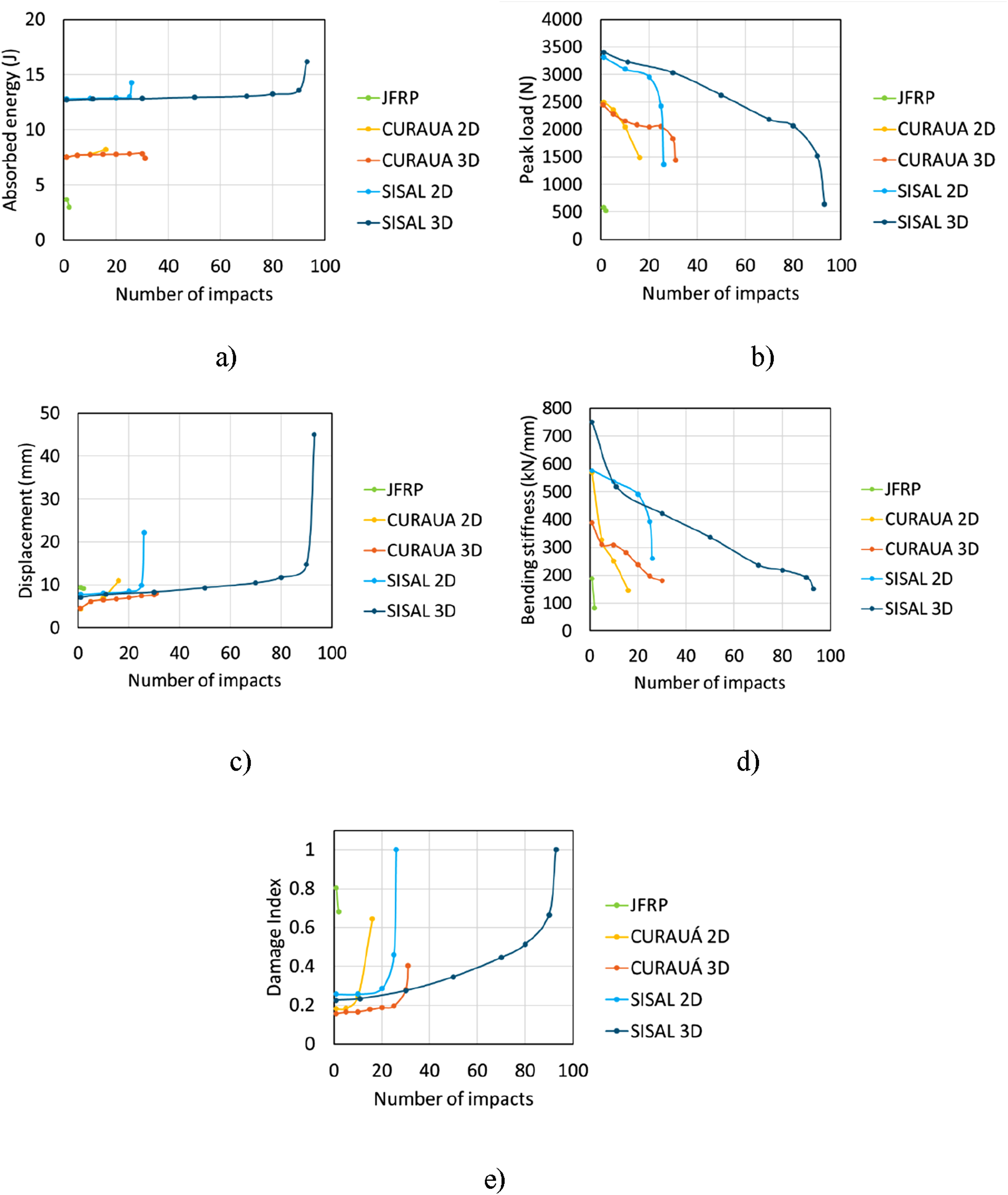
Figure 7 presents the progression of several material parameters as a function of repeated impacts. From Figure 7(a), the evolution of the absorbed energy can be seen. For the neat jute specimens, a quick reduction in AE is visible as a function of impacts. This is mainly due to their brittle nature (i.e., low failure strains). 36 For all the hybrid cases, a stable trend of AE is visible as the number of impacts increases. The progression for all these groups is quasi-linear. Furthermore, as a function of architecture, no significant variation in AE was found when the 2D is compared to the 3D for both CURAUÁ and SISAL specimens. Therefore, the 3D OTT architecture significantly affects the impact fatigue life of the material without degrading the AE.
The SISAL specimens however, presented a significant peak in energy absorption upon failure, due to significant deformation. From Figure 7(b), the progression of peak load as a function of impacts can be seen. It is known in the literature that three regions may be visible; The first region is characterized by a sharp drop in load due to reinforcement fibre micro-buckling and shear deformations; The second region is characterized by a plateau tendency, where the decrease in load continues but at a much slower pace, this is linked to the phenomenon of delamination saturation; In the third and final region, a sharp decrease in peak load is recorded along with significant matrix and fibre cracking and the onset of total specimen failure. 36 These regions are visible in Figure 7(b); however, they may be somewhat difficult to see considering that the energy levels were already significant (i.e., not a very high number of impacts). The regions tend to be more clearly visible at much lower energy impact-fatigue levels (i.e., a high number of impacts to failure). Nevertheless, for the SISAL 2D, 3D and CURAUÁ 3D, the regions are visible. Interestingly, none of these cases presented a sharp decrease from the first to the second impact. Rather, the first and second regions seemed to merge immediately, with a sharp decrease only clearly visible for the third region with the failure of the specimen. Figure 7(c) presents the progression of the maximum displacement as a function of impacts. It can be seen that very limited increases are observed from impact to impact for all cases. The only significant variations occur at failure and only for the SISAL specimens, likely owing to their higher ductility. Finally, regarding the bending stiffness as a function of repeated impacts, the progression can be seen in Figure 7(d) (calculated as maximum load divided by maximum displacement). As expected, the material stiffness decreased as a function of continued impacts, however, different trends were observed as a function of material. For example, the JFRP specimens presented very sharp immediate and significant decreases failing right after. For the hybrid specimens however, the effect of the 3D reinforcement was clearly defined. For both CURAUÁ and SISAL, the 3D reinforcement helped to decrease the initial drop in stiffness and presented a smoother decline. The CURAUÁ 2D presented a significant initial decline followed by slightly smoother decreases till failure. Meanwhile, for the 2D specimens, the SISAL presented a smoother decline at first following a steep decline at the final impact. Finally, from Figure 7(e), the damage index (DI) progression can be seen. This index is used to monitor the damage progression of composites subjected to repeated impacts as a function of the energy and displacement of both repeated and perforation impacts. 35 For both CURAUÁ and SISAL specimens a similar trend can be seen as a function of fibre architecture. The damage index presented a sharp increase for the 2D specimens, while for the 3D, a more linear progression was observed. This is linked to the much lower rate of damage propagation within the composite during repeated impacts for both 3D reinforced composites and further evidence of this is visible in the microCT images (see Section 3.4). Furthermore, the initial DI for all hybrids were in the range of 0.15 to 0.22, while for the JFRP it initiated at 0.8. This significant difference is linked to the fact that for the JFRP, both phases (i.e., matrix and fibre) are predominantly brittle and accumulate high damage at lower strains quickly. Both CURAUÁ and SISAL specimens, however, present higher inherent ductility and resistance when compared to jute (see Table 1) and significantly altered the tendency of the composite to accumulate damage at first impacts.
Impact failure modes
Following an impact event of a projectile to a composite material, different failure modes are possible. These include delamination, matrix cracking, fibre failure, fibre splitting and edge delamination. The type and severity of the failures will depend on parameters such as mass of the projectile/impactor, its geometry, the architecture of the reinforcement, material properties of the fibre and matrix and impact velocity.
7
Figure 8 presents representative side views of the failure modes of the hybrid composites subjected to perforation impact tests. Representative failure modes of the hybrid composites for perforation impact tests: (a) CURAUÁ 2D, (b) CURAUÁ 3D, (c) SISAL 2D and (d) SISAL 3D.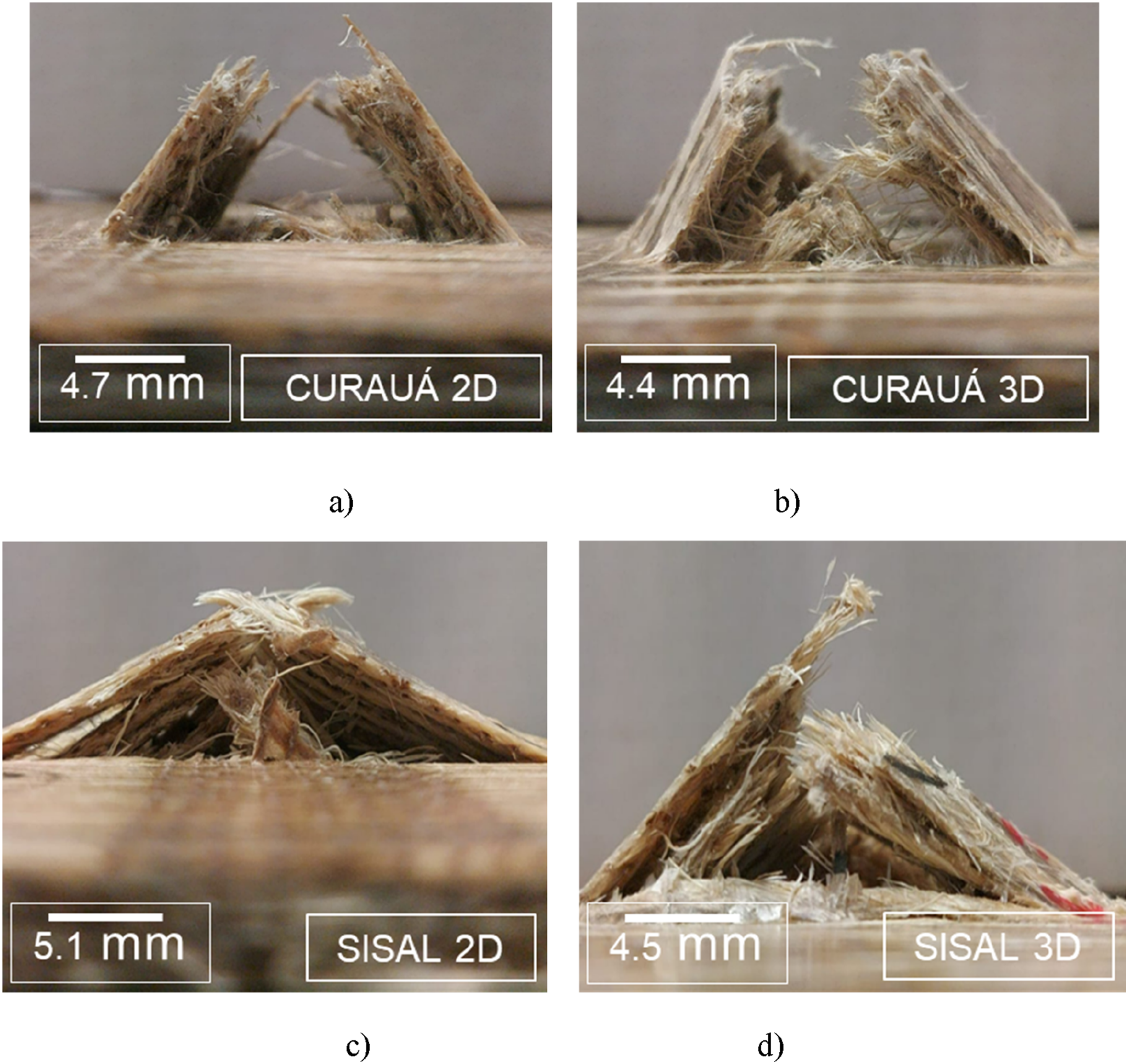
From Figure 8(a), the CURAUÁ 2D perforation failure can be seen in better detail. A significant opening is visible, denoting total matrix and fibre failures in a mostly brittle behaviour. A very similar behaviour can be seen for the 3D counterpart in Figure 8(b). However, it was more difficult for the surfaces to completely separate, suggesting a bridging effect of the 3D fibres. For the SISAL specimens, however, a similar type of failure behaviour is visible for both 2D and 3D (see Figure 8(c) and (d)). In both cases, total opening of the back face failure zone was not visible, the bridging effect was highly significant for both cases, likely due to the high resistance and ductility of the sisal fibre.
Figure 9 presents the representative failure mode progression of the repeated impacts of all cases, for both front and rear of the initial and final impacts. Representative failure modes for the repeated impact tests for all specimens.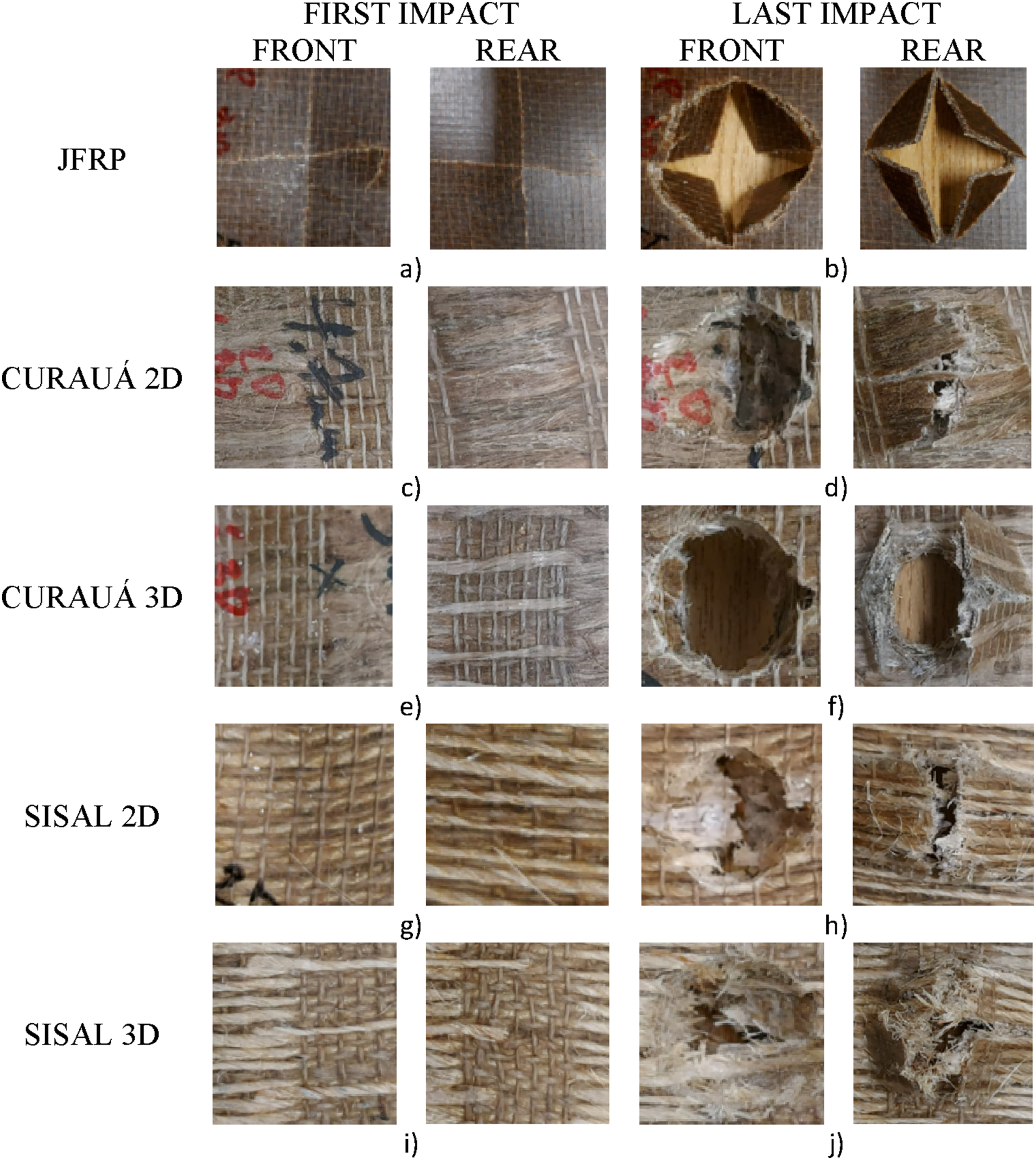
The front image of each case depicts the impact contact face, while the rear image shows the underside of the specimen. The failure zone on the front face presents the direct contact of the impactor, while the rear face failure zone shows the damage propagation in order for the specimen to absorb the impact energy. As a reminder, the impactor was circular with a diameter of 12.7 mm. For the JFRP, from the first impact, a cross shaped crack is visible, followed by a severe brittle failure in the second impact (see Figure 9(a) and (b)). This is due to the fact that both phases (fibre and matrix) and very brittle. 41 These types of impact failures for jute have been previously observed in the literature. 42 The failure progression changes drastically when the hybrid composites are compared to the neat ones. Not only does the failure progresses more slowly, the number of impacts to failure increases significantly. This is in part by the increase in the thickness of the composite, 36 but also due to the higher ductility of the secondary and tertiary (3D) fibre phases, curauá and sisal. For the CURAUÁ 2D specimens, the failure progression can be seen in Figure 9(c) and (d), while for the 3D it is visible in Figure 9(e) and (f). For the CURAUÁ 2D, the impactor contact left barely visible impact damage (BVID), while for the rear face, crack propagation became easily recognizable near the surface crossing the CURAUÁ 2D fibre bundles at the 10th impact. By the 16th and final impact, a predominantly brittle failure can be seen on the front face, where an ellipsoidal cave in marks the total failure on the specimen, while on the rear face a lifting of two surfaces with a total specimen crack in the middle is visible. Matrix cracking, and fibre failure are the dominant failure mechanisms.
For the CURAUÁ 3D specimens, the failure became more significant closer to the 30th impact (see Figure 9(e) and (f)) with a rounded cave in on the front face and a cross shaped crack on the rear face. The following impact marked the composite failure and a similar failure to the CURAUÁ 3D is visible, however, at almost twice the number of impacts. The impact failure evolution for the SISAL 2D can be seen in Figure 9(g) and (h). It can be seen that the failure is similar to the previous hybrids in its predominant brittle tendency in matrix cracking and fibre failures, however, it can also be seen that a large crack began to form at the impact zone propagating to the ends of the specimen in the space between sisal intralaminar reinforcement fibres (see Figure 9(h)). This corroborates the hypothesis posited earlier that large surfaces are created during each impact as the resin progressively debonds from the sisal fibres, absorbing significant amounts of energy. This will be further discussed in the next section. The failure modes of the SISAL 3D can be seen in Figure 9(i) and (j). Most notably, the damage was BVID, until close to the 60th impact, indicating the capacity of the sisal transverse reinforcement to contain significant deformations. When the visible failures began, especially on the back face, fibre failure was more evident at first than matrix cracking. Even at the top face, the deformations were much more limited, especially when compared to the JFRP and SISAL 2D. Differently to the SISAL 2D, no massive cracks spanning the entire specimen were observed. This may be one of the reasons why the SISAL 2D absorbed more energy in perforation by being able to create large matrix debonding surfaces that were blocked from progressing by 3D fibre crack arrestment. Therefore, for the SISAL specimens, the 3D reinforcement offers a positive and a negative in terms of LVI, the 3D offers significantly higher impact fatigue life, however, a lower total AE at perforation is expected.
MicroCT analysis of impact specimens
Figure 10 presents the micro tomography images of the impact specimens after full penetration (xy (normal) and zy (parallel to the fibres) plane views). Representative microCT scans of all tested samples for perforation specimens on both cross-sectional planes, (a) CURAUÁ 2D and 3D (xy plane), (b) CURAUÁ 2D and 3D (zy plane), (c) SISAL 2D and 3D (xy plane), (d) SISAL 2D and 3D (zy plane), (e) SISAL 2D (top surface) and (f) SISAL 3D (top surface).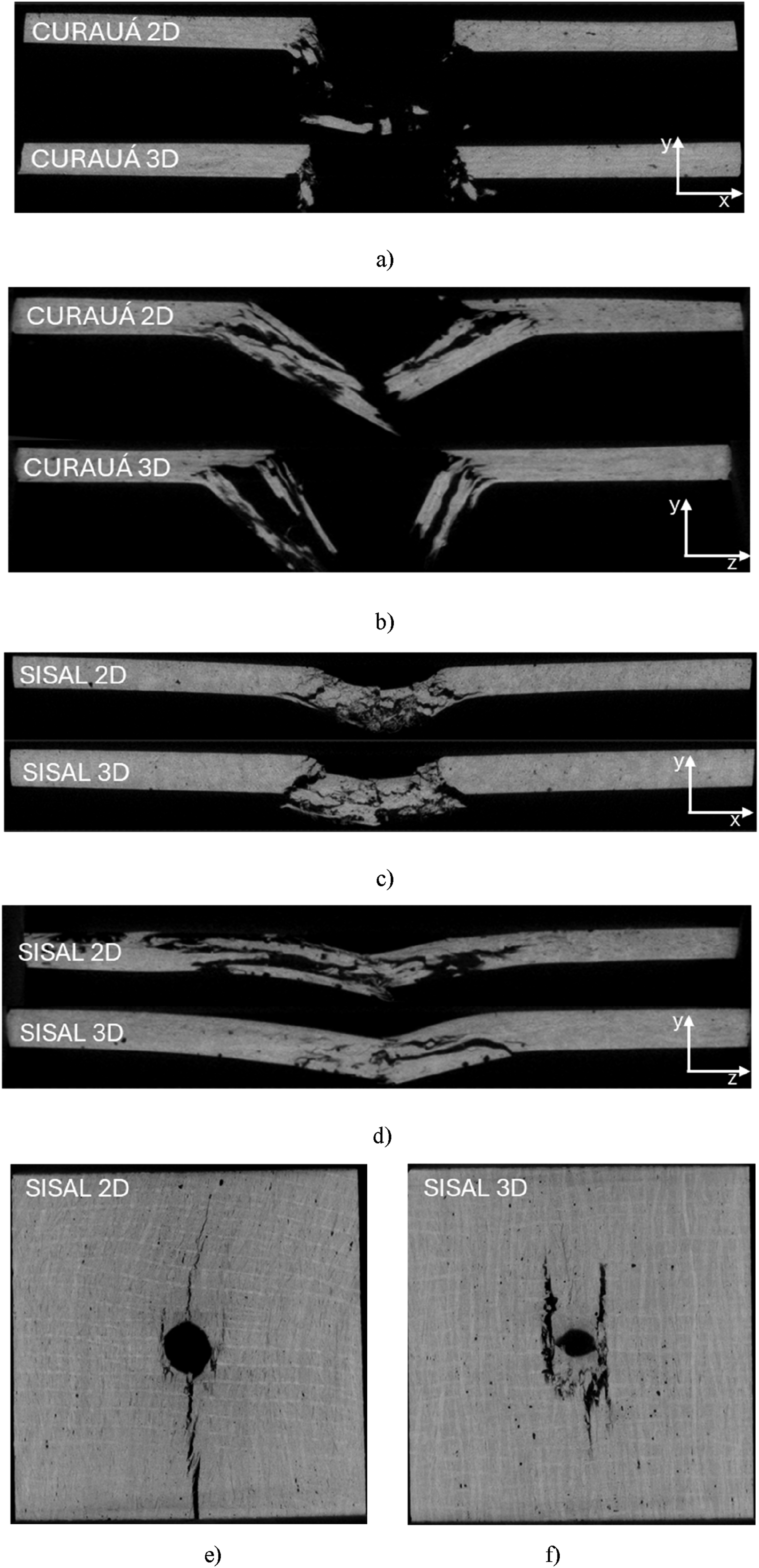
It can be seen that for all cases, no significant voids (dark dots) are interacting with any crack nucleation sites in a meaningful way, therefore it is assumed that they are not relevant for the large-scale damage propagation. 43 It is apparent that for all the CURAUÁ reinforced specimens, no significant crack propagation occurred from the main perforation site across the specimens on both planes (see Figure 10(a) and (b)). This further supports the quantitative observation of the perforation impact dataset from section 3.1, where no significant variation was found in absorbed energy, peak load or deformation between the CURAUÁ 2D and 3D specimens. This is likely due to the strong fibre/matrix adhesion and mechanical interlocking of the CURAUÁ/epoxy, which makes it inherently difficult for interlaminar and interphase cracks to form and propagate. 44 Furthermore, the more brittle failure of the CURAUÁ specimens is also clear when compared to the SISAL specimens. In contrast, for the SISAL specimens a more significant variation in crack propagation as well as matrix cracking was observed as a function of architecture. From Figure 10(c) and (d), it can be seen that no significant cracks propagated on the xy plane, similar to the CURAUÁ, however, highly significant cracking was observed on the zy plane for the SISAL 2D case. The SISAL 3D case, one the other hand, presented a much more controlled crack development only near the main impact zone, without significant cracks developing across the zy plane. From Figure 10(e) and (f) the representative top view tomography of the impact side of the perforation SISAL specimens are visible. It is clear that a large crack propagated from the main impact zone in the zy plane all the way through the specimen for the SISAL 2D case. Furthermore, significant crack development is visible on either side of the mostly circular impact zone (stress concentrations, see Figure 10(e)). Moreover, fibre bridging can be seen near the bottom of the image where SISAL tows diverted the crack as it developed through the matrix region between intralaminar reinforcements. On the other hand, for the SISAL 3D top failure view, a much more controlled crack development was observed, where the cracks propagated only on either side of the impact zone (see Figure 10(f)). This is directly linked to the fibre architecture where the transverse reinforcement arrested the crack development. These microCT analyses corroborate the previous discussion whereby the mechanics of local debonding of fibre/matrix, very large new surface areas are formed and absorb significant energy in the process. This phenomenon is the main reason for the higher energy absorption of the SISAL 2D specimen under perforation impact testing, while for fatigue (repeated) LVI, the crack arrestment mechanism afforded by the transverse reinforcement nearly quadruples the impact life until failure. In other words, energy dissipation capacity is proportional to crack density.6,45 Furthermore, z-binder yarn debonding tendency during impact events is linked to differences in elastic modulus. 46 Therefore, design factors may be implemented such that if a significant single energy impact is expected at some point in the life of the part, the SISAL 2D architecture is preferable, however, if impact fatigue is likely, the 3D reinforcement is more effective.
Conclusions
In this research, novel 3D fibre reinforced hybrid composites were fabricated using two distinct techniques: intralaminar (2D) and orthogonal-through-the-thickness (3D-OTT). Perforation and repeated LVI fatigue tests were conducted to assess the maximum energy absorption and load-bearing capacity of the composites, as well as their fatigue life under repeated low-energy impacts. The following conclusions can be drawn: • 3D reinforcement is highly effective in mitigating crack propagation during impact loading. In CURAUÁ fibre composites, both 2D and 3D architectures exhibited similar perforation energy and peak load values, attributed to strong fibre–matrix interlocking and minimal crack development. In contrast, SISAL composites showed reduced energy absorption in the 3D configuration, which is linked to fibre debonding and less effective load transfer during impact. • The total absorbed energy at perforation was strongly influenced by both the fibre type and reinforcement architecture. When compared to jute-based reference composites (JFRP), CURAUÁ and SISAL fibre-reinforced composites achieved thickness-normalized energy absorption increases of approximately 30% and 50%, respectively. Notably, reinforcement architecture had a limited effect on CURAUÁ composites, while SISAL composites in 2D configuration outperformed their 3D counterparts by about 15% in perforation energy. • For repeated impact tests, the 3D reinforcement architecture significantly improved performance, enhancing fatigue impact life by 2 times for CURAUÁ specimens and 3.6 times for SISAL specimens. • Micro-CT imaging revealed distinct crack arrest mechanisms for the two fibre types. The CURAUÁ specimens presented an inherent crack-blunting effect for both 2D and 3D configuration, owing to the good fibre/matrix interface quality and mechanical interlocking. In contrast, the SISAL specimens presented significant crack development following impact (in the yz plane, parallel to the fibres) for both 2D and 3D configuration. However, the 3D case showed a higher capacity to limit crack propagation. • A potential immediate industrial application lies in the semi-structural automotive sector, where composite panels exposed to environmental conditions must exhibit robust impact fatigue performance—similar to commercially available flax-based panels such as those by BComp®. Notably, the impact fatigue behavior of SISAL 3D composites was comparable to published data for 2D glass fiber-reinforced plastics (GFRP) and demonstrated similar peak load capacity and energy absorption characteristics to 3D woven GFRP composites.
Footnotes
Acknowledgements
This work was partially supported by the Brazilian Research Agencies: Coordenação de Aperfeiçoamento de Pessoal de Nível Superior - Brasil (CAPES) - Finance Code 88881.933701/2024-01 and National Council for Scientific and Technological Development (CNPq) - Grant number 310268/2023-0. https://www.j-tech.polito.it We would like to thank Ana Paula Pagnoncelli for her support and expertise in Micro-Computed tomography analysis. This activity was partially developed in the frame of J-TECH@POLITO Advanced Joining Technology at Politecnico di Torino; ![]() . This work was developed within the scope of the project CICECO-Aveiro Institute of Materials, UIDB/50011/2020 (DOI 10.54499/UIDB/50011/2020), UIDP/50011/2020 (DOI 10.54499/UIDP/50011/2020) & LA/P/0006/2020 (DOI 10.54499/LA/P/0006/2020), financed by national funds through the FCT/MCTES (PIDDAC).
. This work was developed within the scope of the project CICECO-Aveiro Institute of Materials, UIDB/50011/2020 (DOI 10.54499/UIDB/50011/2020), UIDP/50011/2020 (DOI 10.54499/UIDP/50011/2020) & LA/P/0006/2020 (DOI 10.54499/LA/P/0006/2020), financed by national funds through the FCT/MCTES (PIDDAC).
Author contributions
Conceptualization, writing—original draft preparation, H.F.M.d.Q and M.D.B.; methodology, H.F.M.d.Q. and R.C.; supervision, M.D.B. and R.C.; validation, R.C. and M.D.B.; writing—review & editing, H.F.M.d.Q and M.D.B. All authors have read and agreed to the published version of the manuscript.
Declaration of conflicting interests
The authors declared no potential conflicts of interest with respect to the research, authorship, and/or publication of this article.
Data Availability Statement
Data will be made available upon reasonable request.