
Abstract
This study evaluates the impact response and damage tolerance of carbon fiber-reinforced polymer (CFRP) composites with varying Aramid pulp reinforcement ratios subjected to low-velocity impact (LVI) at an energy level of 5 J. Pristine (unreinforced) and reinforced samples with 1X, 2X, and 4X Aramid pulp ratios were analyzed through drop-weight impact tests, flexural tests, and micro-CT scans. Results indicate that increasing reinforcement enhances energy absorption and maximum displacement but decreases peak force due to improved load distribution via delamination and matrix cracking. While 4X reinforced samples exhibit the highest energy absorption, they also show the most significant internal damage, including extensive delamination, void formation, and intralaminar failure. Flexural behavior reveals a decreased in stiffness and strength with higher reinforcement levels, which is attributed to weak fiber-matrix adhesion and resin-rich zones. Optimal reinforcement was observed at 2X, where flexural strain peaked due to effective crack bridging. Excessive reinforcement led to agglomeration effects, exacerbating void formation and structural weakening. The findings underscore the importance of optimizing reinforcement ratios and ensuring uniform dispersion to balance between energy dissipation and mechanical performance in CFRP laminates.
Introduction
Carbon fiber-reinforced polymers (CFRPs) are extensively utilized in aerospace, naval, green energy, and automotive industries due to their lightweight nature, high specific strength, excellent stiffness, and customizable mechanical properties.1,2 While CFRPs exhibit exceptional in-plane mechanical properties along the fiber direction, their out- of-plane (through-the-thickness) mechanical properties are significantly weaker. This weakness is primarily attributed to resin-rich interlaminar regions between fiber layers, which are inherently more prone to damage. These interlaminar regions provide pathways for cracks to propagate through the brittle matrix, making the material highly susceptible to delamination. A critical drawback of CFRP laminates is their low resistance to impact damage due to their layered structure. Low-velocity impact (LVI) is defined as impact occurring at velocities below 10 m/s, 3 often results in barely visible impact damage (BVID) on the surface while potentially causing severe
Internal damage, such as delamination, matrix cracking, and fiber breakage. 4 Research on the LVI response of CFRPs have extensively examined pristine laminates at room temperature (RT)5–14 and at low temperatures.15–20 Commonly observed failure mechanisms include matrix cracking, fiber pullout, and delamination, with delamination being particularly concerning as it severely reduces material strength and is difficult to detect.21–27 To address these vulnerabilities, numerous interlaminar reinforcement techniques have been explored, including Z-pinning,28–32 3D weaving,20,33,34 stitching,35–37 tufting,38–41 interleaving with short fibers,42–44 and nanomaterials such as graphene nanoplatelets45–49 and ZnO nanowires.50–52 These methods have demonstrated significant improvements in through- thickness mechanical properties but often come with drawbacks, including increased manufacturing costs, added complexity, and potential reductions in in-plane properties. 53 The effects of varying reinforcement amounts have been studied for some techniques to identify optimal quantities. For instance, Kravchenko et al. 54 investigated the effect of through-thickness reinforcement rod aspect ratios on mode I delamination fracture resistance in composite laminates. They conducted experiments to analyze the stress transfer and fracture resistance. Results showed that increasing the aspect ratio of reinforcement rods significantly improved delamination fracture resistance by reducing interfacial shear stresses. They concluded that optimizing reinforcement aspect ratios is crucial for enhancing laminate toughness, especially in applications requiring high fracture resistance.
Li et al. 55 studied the effect of varying adhesive quantities (0 g/m2, 20 g/m2, 40 g/m2, and 60 g/m2) on the failure behavior and mechanical properties of fiber metal laminates (FMLs) based on aluminum-lithium alloys. They investigated interlaminar, tensile, flexural, and fatigue properties across different adhesive quantities. Results revealed that moderate adhesive quantities (40 g/m2) significantly enhanced the interlaminar and mechanical properties, while excessive adhesive amounts degraded performance due to increased brittleness. The failure modes varied with adhesive quantity, influencing mechanical behavior under different loading conditions. The authors recommended 40 g/m2 as the optimal adhesive quantity for balanced performance in FMLs.
Rodr´ıguez-Gonza´lez and Rubio-Gonza´lez 56 investigated the effects of varying concentrations of multi-walled carbon nanotubes (MWCNTs) (0.05% to 0.2% wt.) sprayed onto carbon fiber/epoxy composite surfaces. Mode I and II interlaminar fracture toughness were assessed using double cantilever beam (DCB) and end-notched flexure (ENF) tests. The results revealed that fracture toughness peaked at 0.05% MWCNTs due to the interfaces’ effective nanotube bridging and pullout mechanisms. At higher concentrations, the formation of nanotube agglomerations reduced interfacial adhesion and weakened the laminate’s performance. This study emphasizes optimizing MWCNT content to enhance interlaminar fracture toughness without compromising interface quality.
Recently, micro-length Aramid fibers (pulp) have been investigated as interlaminar reinforcements, showing promise in enhancing through-thickness properties without significantly altering the manufacturing process.57–59 Ye et al. 58 studied the compression-after-impact (CAI) performance of carbon fiber composites with interlays of Aramid pulp micro-/nanofibers, using impact energies of 3.8 and 9.3 J. CAI tests revealed that the aramid microfibers reduced delamination by creating a “linking” effect between the carbon fiber layers, localizing damage and absorbing impact energy. They also found that Aramid pulp increased CAI strength by up to 86.7%. Yang et al. 60 explored the enhancement of basalt fiber reinforced polymer (BFRP) composites by introducing Aramid pulp fibers with micro-fiber trunks and nano-fiber branches as interleaving material. This approach improved flexural strength and elastic modulus while promoting quasi- vertical fiber bridging in the interfacial transition zone, preventing crack propagation along the BF/epoxy interface. Three-point bending tests showed that 4 g/m 2 Aramid pulp interleaving increased flexural strength by 63.4% and elastic modulus by 47.1% compared to baseline composites. In addition to strengthening through-thickness properties, Aramid pulp offers the advantage of ease in manufacturing. As a matrix modification through micro- fibers, it can be integrated into large-scale operations for commercially reinforced prepreg composites. 59 Despite these advancements, there remains a lack of research on the effects of varying Aramid pulp reinforcement ratios, particularly for CFRP laminates subjected to LVI. To the best of the authors’ knowledge, no detailed studies have investigated how different reinforcement quantities influence the impact response, damage mechanisms, and mechanical performance of CFRP laminates. This study aims to address this gap by evaluating the impact behavior and failure mechanisms of CFRP composites with varying Aramid pulp reinforcement ratios, which provides insights into optimal reinforcement levels for enhancing damage tolerance and structural performance.
This study investigates the effect of varying Aramid pulp reinforcement ratios on the mechanical performance and damage tolerance of woven carbon fiber-reinforced polymer (CFRP) laminates subjected to low-velocity impact (LVI). Laminates were fabricated using vinyl- ester resin and evaluated in pristine (unreinforced) and reinforced configurations with 1X, 2X, and 4X Aramid pulp reinforcement ratios. Drop-weight impact tests were conducted at an impact energy of 5 J to assess key parameters such as contact force (N), displacement (mm), energy absorption (J), impact duration (ms), and degree of damage (DD). Flexural tests were also performed on resin samples to evaluate the influence of Aramid pulp reinforcement on flexural stiffness, strength, and strain behavior. Micro-CT scans were employed to characterize internal damage mechanisms, including delamination, void formation, and intralaminar failures, in both unreinforced and reinforced samples. The study further examines the trade-offs associated with increasing reinforcement ratios, particularly the relationship between improved energy absorption and increased internal damage. The paper is organized as follows: the “Materials and Methods” section comprehensively describes laminate fabrication, mechanical testing procedures, and micro-CT analysis. The “Results and Discussion” section details the impact and flexural performance findings, highlighting correlations between reinforcement ratio and mechanical behavior. The section concludes with an in-depth analysis of the damage mechanisms identified through micro-CT. The paper concludes by summarizing the key results of the study.
Materials and Methods
The material system is introduced initially, followed by the process of sample fabrication, specimen preparation, and, lastly, the experimental setup.
Material system
Mechanical properties of woven carbon fiber and vinyl ester resin.
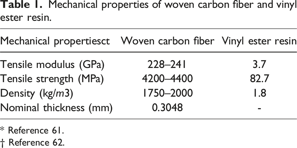
* Reference 61.
† Reference 62.
Woven fabric was chosen because, compared to unidirec- tional fibers, its fiber architecture offers better resistance to crack propagation. 64 Vinyl ester resin was chosen because it is commonly used in marine applications and offers excellent UV and corrosion resistance.65,66 Aramid pulp was selected because it has a hierarchical microfiber structure that provides through-thickness reinforcement and creates a fiber-bridging effect, which can alter the interfacial cracking behavior in CFRP. 59 Carbon fibers were selected due to their high strength and modulus. 67
Resin Preparation
This section will first outline the preparation process for the unreinforced resin and then the steps for preparing the reinforced matrix.
Preparation of the unreinforced matrix
A vinyl ester resin was mixed with MEKP hardener in a weight ratio of 100:1.25, as per the manufacturer FibreGlast’s guidelines. 63 The mixture was then placed in a desiccator to remove any trapped air bubbles.
Preparation of the aramid pulp-reinforced matrix
The Aramid pulp provided by the manufacturer comes in compacted pellets, also called clumps or closed pellets, where the microfibers are tightly packed, as illustrated in Figure 1(a). A Krupps flat-blade, commercial-grade coffee grinder was utilized at 20,000 r/min to disperse these clumps. The Aramid pulp was placed in the grinder, ensuring it filled no more than half of the grinder’s capacity to avoid fiber compaction during dispersal. The grinder operated in 20- second bursts, pausing any fibers that adhered to the lid due to static. This process was repeated three times, successfully breaking up the clumps and producing loose, fluffy fibers without the rounded edges of the original pellets, as shown in Figure 1(b). Once the Aramid pulp was fully dispersed, it was blended into the pre-mixed vinyl resin/MEKP solution, which had been stirred for 5 minutes as outlined in the “Preparation of the unreinforced matrix” subsubsection. The resin-to-Aramid pulp ratio was controlled at three levels by volume: 15:1 (1X Aramid pulp-reinforced resin), 15:2 (2X Aramid pulp-reinforced resin), and 15:4 (4X Aramid pulp-reinforced resin), by guidelines from the manufacturer, FibreGlast.
63
Instead of traditional methods for opening Aramid pulp, such as immersing the clumps in acetone before blending, a blender was chosen. This approach allows for easy integration into industrial settings without requiring changes to existing composite manufacturing processes. By skipping the acetone drying step, the pulp can be processed as soon as it arrives, using a commercially available blender to create open Aramid pulp that is ready for immediate use. (a) Agglomerated (closed) Aramid pulp and (b) Post-processed (open) Aramid pulp.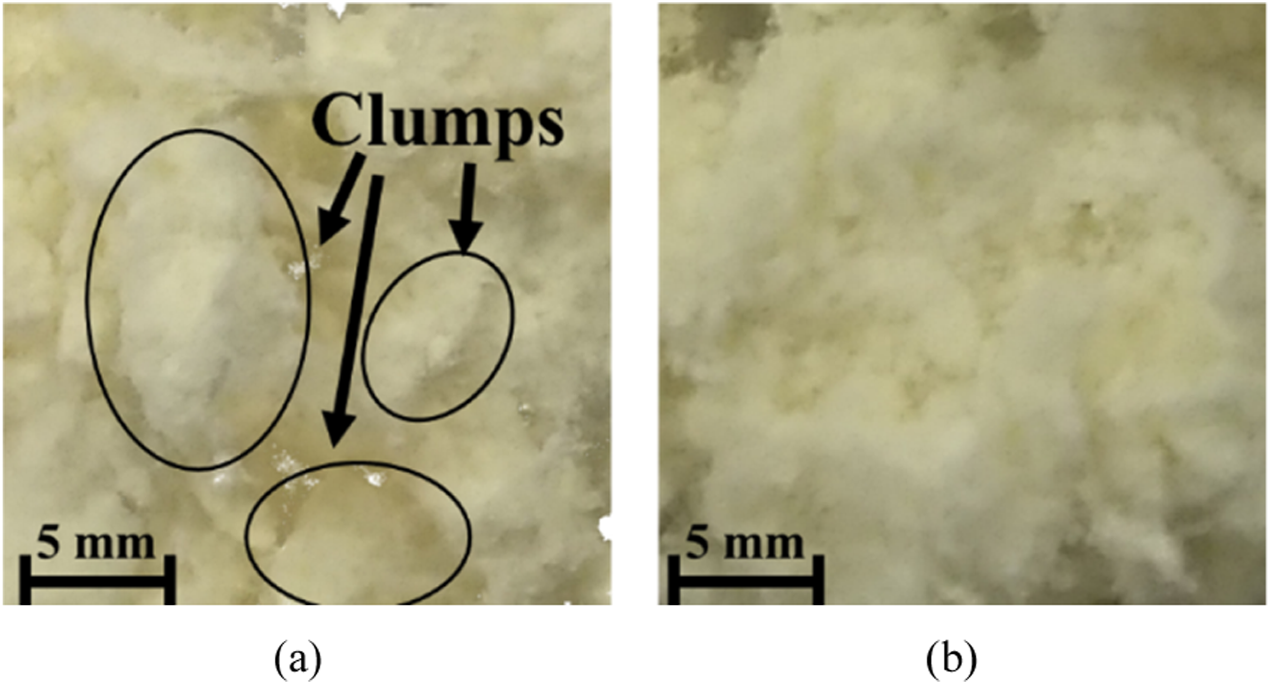
Samples manufacturing
This section will detail the manufacturing process for both pristine and Aramid pulp-reinforced CFRP composite laminates, along with the preparation of flexural samples for pristine and Aramid pulp-reinforced resins.
Manufacturing of pristine CFRP and aramid pulp- reinforced CFRP composites
Four sets of CFRP laminates were manufactured: pristine laminates (without interlami- nar reinforcement), 1X Aramid pulp-reinforced laminates (with the manufacturer’s recommended reinforcement), 2X Aramid pulp-reinforced laminates (double the recommended reinforcement), and 4X Aramid pulp-reinforced laminates (four times the recommended reinforcement). The pristine CFRP composites and the Aramid pulp-reinforced interlam- inar CFRP composites were manufactured using the hand lay-up method. The main difference between them is the inclusion of Aramid pulp reinforcement in the reinforced samples. Figure 2 shows the manufacturing process for the reinforced CFRPs. All the pristine and reinforced CFRPs followed the same process, including the cutting of samples. Laminates were made with 16 layers of woven carbon fabric, each cut to 350 mm × 350 mm. Two aluminum molds, each 381 mm × 381 mm, were wrapped with Stretchlon® 800 Bagging film. A Teflon sheet, also 381 mm × 381 mm, was placed on one mold to facilitate laminate removal after curing. The first woven carbon layer was laid down, and resin was applied and spread with a silicone squeegee. This process was repeated 16 times for the pristine samples (with unreinforced resin) and the reinforced samples (1X, 2X and 4X Aramid pulp-reinforced resin). Once the lay-up was complete, the Teflon sheet and second aluminum mold were placed on top of the laminate. The laminate was then placed in a Wabash Genesis hydraulic press, applying a uniaxial pressure of 2 MPa at room temperature (25°C) for 2 hours. After the curing process, the laminate was removed from the press and left to rest for 24 hours to ensure full curing, as recommended by the manufacturer FibreGlast. A total of four laminates were produced (1 pristine, 1 1X Aramid pulp- reinforced, 1 2X Aramid pulp-reinforced, and 1 4X Aramid pulp-reinforced CFRPs). After the 24-h resting period, the laminates were cut into specimens measuring 150 mm in length x 100 mm in width using an in-house Wazer desktop waterjet cutter. This ensured smooth edges and reduced the risk of delamination. These dimensions were based on the ASTM D7136M-20 “Standard Test Method for Measuring the Damage Resistance of a Fiber-Reinforced Polymer Matrix Composite to Drop-Weight Impact Event”.
68
After cutting, specimens were set aside for another 24 hours to completely dry. The thicknesses of the CFRP laminates were as follows: pristine laminates measured 4.2 ± 0.2 mm, 1X reinforced measured 4.2 ± 0.3 mm, 2X reinforced measured 4.3 ± 0.3 mm, and 4X reinforced measured 4.35 ± 0.2 mm. A total of 20 specimens were prepared, consisting of five specimens each of pristine, 1X reinforced, 2X reinforced, and 4X reinforced laminates. Manufacturing of Aramid pulp-reinforced CFRP specimens.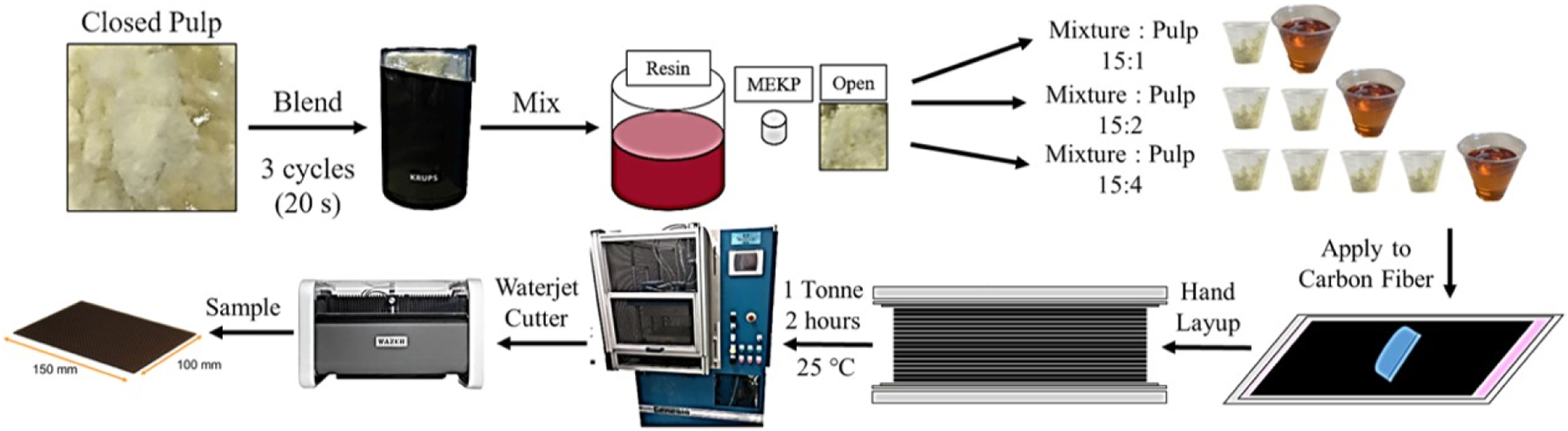
Manufacturing of pristine and aramid pulp-reinforced resin specimens
In order to evaluate the effect of Aramid pulp as an interlaminar reinforcement in CFRP, the flexural responses of pristine resin samples were compared with those reinforced with 1X, 2X, and 4X Aramid pulp. Flexural testing offers valuable insights into how Aramid pulp redistributes stress and mitigates crack propagation under bending loads, simulating the localized stresses seen during impact. This analysis provides details of Aramid pulp’s role in enhancing CFRP laminates’ impact resistance and overall response to out-of-plane loading conditions. The specimens were manufactured using 3D-printed molds according to ASTM D790-17, the “Standard Test Methods for Flexural Properties of Unreinforced and Reinforced Plastics and Electrical Insulating Materials.” The resin preparation for both the pristine and Aramid pulp-reinforced matrices followed the method outlined in the “Resin Preparation” subsection. Figure 3 illustrates the manufacturing process for the reinforced resin samples, though the same process was applied to both pristine and reinforced samples. After preparing the matrix (either pristine or reinforced), it was poured into the 3D-printed molds. During curing, the heat generated by the matrix can cause mold deformation, which may result in sample distortion. To prevent this, a piece of bagging film was placed over the mold to facilitate easy specimen removal, followed by an aluminum plate positioned on top of the specimen to maintain dimensional stability during curing. The samples were then left to cure for 24 hours, as recommended by the manufacturer, FibreGlast. A total of 20 samples were manufactured: five pristine, 5 with 1X reinforcement, 5 with 2X reinforcement, and 5 with 4X reinforcement. After being removed from the 3D-printed mold, the specimens measured an average of 64 mm in length and 12.7 mm in width, with a consistent thickness of 3.25 ± 0.1 mm across all samples. Manufacturing of Aramid pulp-reinforced resin specimens.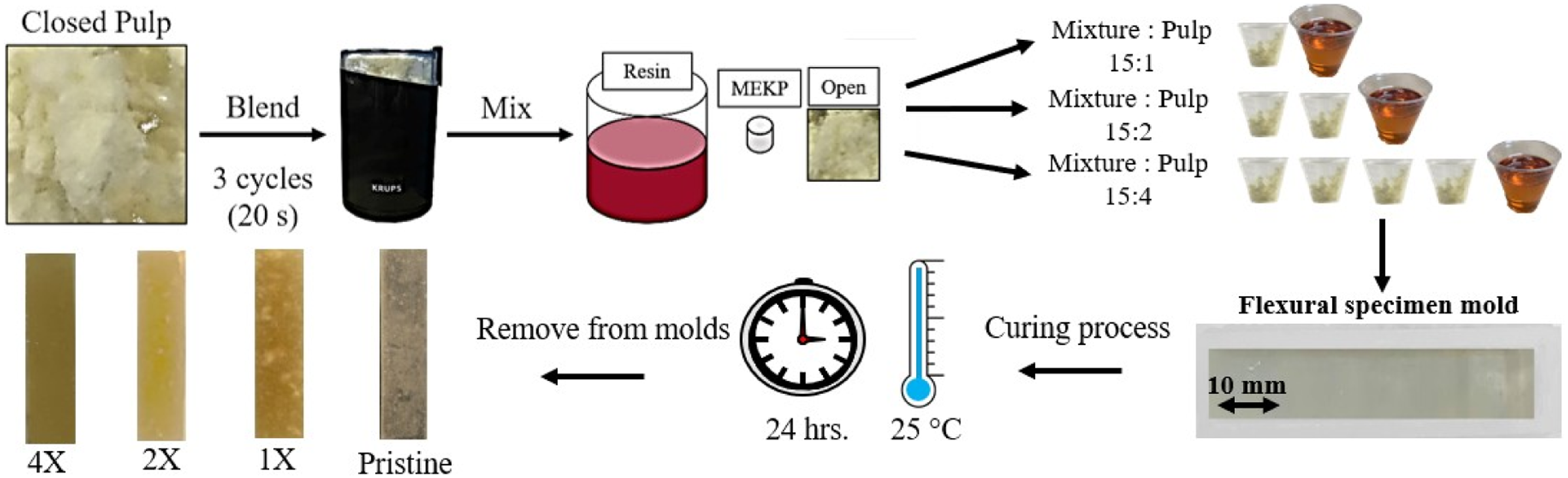
Impact testing
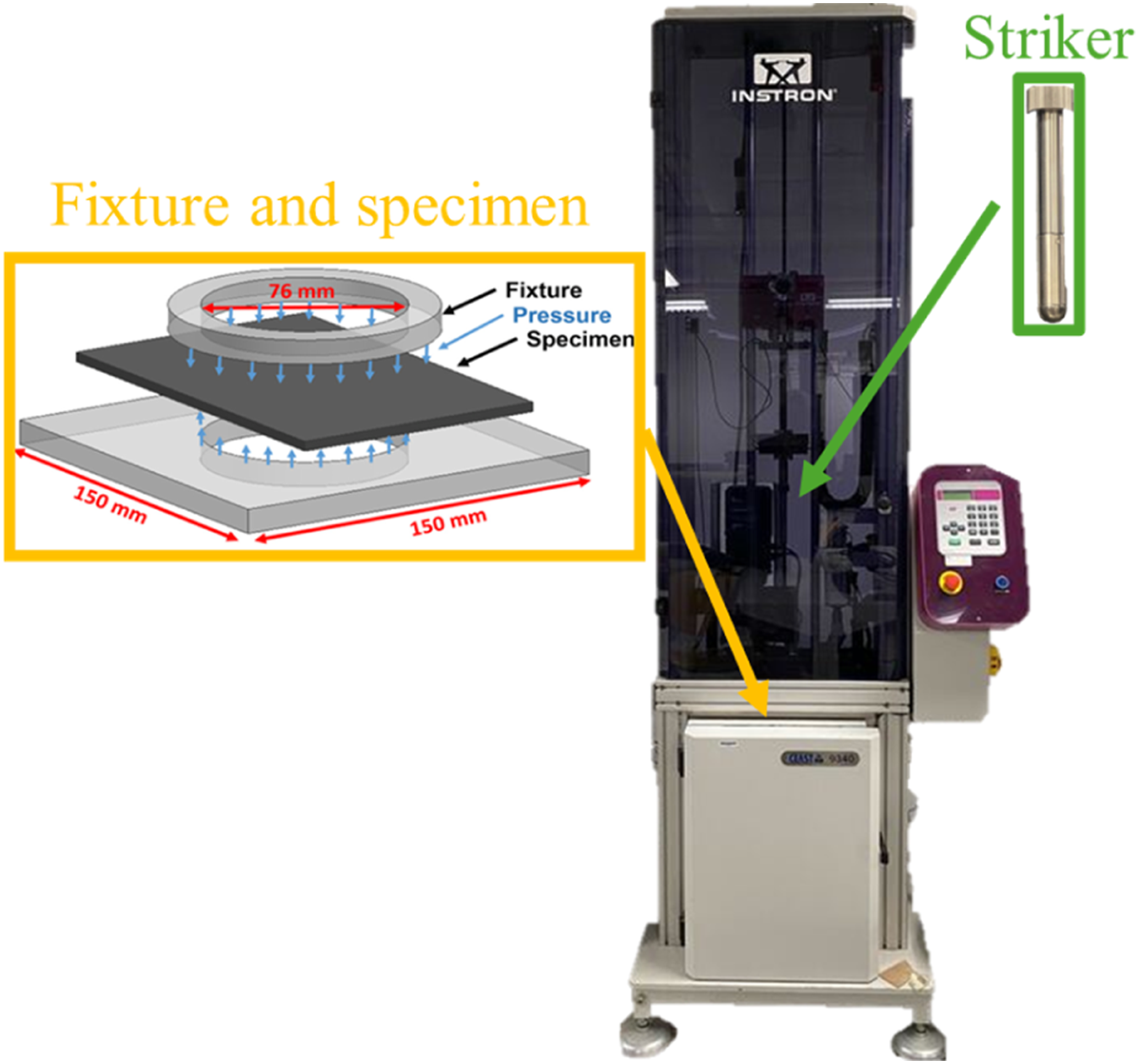
A total of 20 specimens were cut using a water jet for impact testing, comprising five specimens each of pristine, 1X reinforced, 2X reinforced, and 4X reinforced laminates. All specimens, both pristine and reinforced CFRP (1X, 2X and 4X), were tested under a low-velocity impact (LVI) energy level of 5 J. LVI tests were conducted using an Instron CEAST 9340 drop tower impact machine equipped with an anti-rebound device. The specimens were positioned over a steel frame with a circular opening of 76 mm in diameter, as shown in Figure 4. A steel hemispherical striker, 12.5 mm in diameter and weighing 3.1 kg, was used for all impact events. The impact energies were calculated using the Kinetic Energy (KE) equation (1): Impact test setup using Instron CEAST 9340 impact test maschine.
The selected impact energies of 5 J corresponded to a low impact velocity of 1.82 m/s. This range was chosen to induce barely visible impact damage (BVID) on the laminate’s surface while ensuring sufficient internal damage to the laminate. The Instron impact machine determined the striker’s velocity by adjusting the initial height of the striker relative to its internal photocell, based on the potential energy (PE) equation (2):
Flexural testing
A total of 20 samples were manufactured, including five pristine samples and five samples each with 1X, 2X, and 4X reinforcement. The flexural specimens were designed in accordance with ASTM D790-17,
69
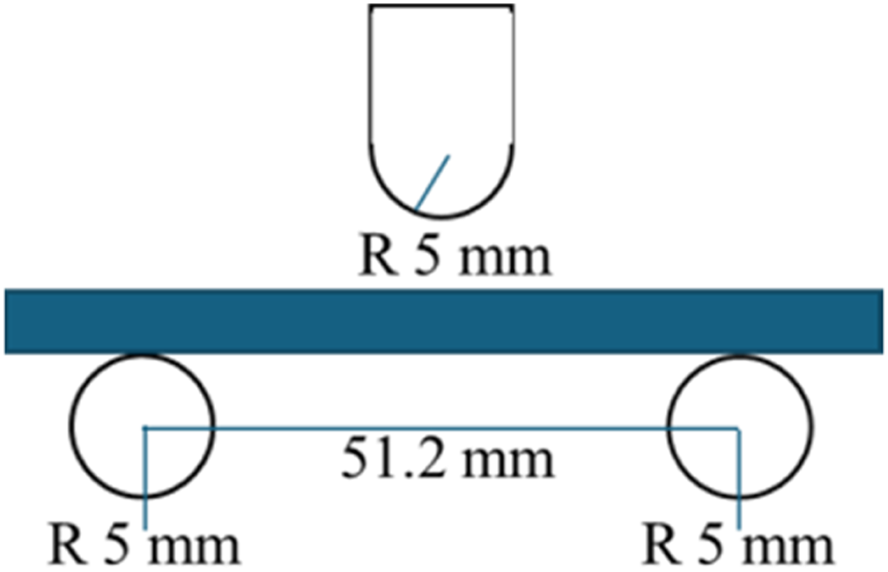
maintaining a span- to-thickness ratio of 16:1. Flexural testing was conducted using an ADMET eXpert 1000 machine with a 2.2-kN load cell. Figure 5 shows an schematic of the flexural fixture dimensions. To ensure compliance with ASTM D790-17, the initial test was conducted at a crosshead speed of 1.3 mm/min, determined based on the specimen dimensions and following Procedure A of the standard. During testing, each specimen was bent until either fracture occurred or the maximum flexural strain reached 5%, whichever came first. For pristine samples, no failure occurred within the 5% strain limit. Thus, per ASTM D790-17 (Procedure B), the crosshead speed was increased to 13 mm/min, which was then consistently applied to all pristine resin samples. Conversely, fracture occurred before reaching 5% strain for all Aramid pulp-reinforced specimens. Therefore, following ASTM D790-17 (Procedure A), a crosshead speed of 1.3 mm/min was maintained. This adjustment ensured that testing conditions aligned with the material behavior at different reinforcement levels while adhering to the prescribed ASTM procedures. The flexural stress and strain were calculated using equation (3) and (4), respectively. Flexural modulus, strength, and failure strain were calculated according to ASTM D790-17. Flexural fixture dimensions.

X-ray micro-computed tomography (micro-CT) scanning
One impacted sample from both the unreinforced and Aramid pulp-reinforced panels underwent X-ray micro-CT scanning at the Materials and Manufacturing Directorate of AFRL at WPAFB. A rectangular section measuring 48 mm in width and 51 mm in length was cut from the damaged area of the original 150 mm × 100 mm panels. The scans were performed using a Carl Zeiss Xradia Versa 520 with an Air filter, at a resolution of 6.8 µm and an X-ray tube voltage of 120 kV. The images had a resolution of 966 × 731 pixels per slice, with scan depths ranging from 700 to 800 slices per specimen. No thresholding or additional modifications were applied, and images were analyzed without overlays. Image reconstruction was completed using Dragonfly 3D World software (version 2024.1.0.1601) developed by Commet Technologies Canada Inc. The region of interest (ROI) was selected to focus on (e.g., the impact zone, delamination areas, fiber-matrix debonding zones, etc.), ensuring accurate characterization of internal damage mechanisms.
Results and Discussion
The low-velocity impact (LVI) responses of the laminates were assessed by analyzing contact force (N), displacement (mm), energy (J), and time (ms) at an impact energy of 5 J. Flexural testing of the resin samples was conducted to evaluate the effects of varying reinforcement ratios on their flexural behavior. Additionally, a post-impact visual inspection using an optical microscope was performed to assess barely visible impact damage (BVID) on both the impacted surface and the back face of the samples. A micro- CT scan was also carried out on the reinforced laminates to measure the extent of internal damage after impact.
Impact response
Force-time histories
Figure 6 presents the force-time graphs for CFRP laminates subjected to a 5 J impact: pristine (unreinforced) in 6(a), 1X reinforced in 6(b), 2X reinforced in 6(c), and 4X reinforced in 6(d). A typical force-time graph during an LVI begins with the striker contacting the laminate, causing the force to increase. As shown in Figure 6(a) (pristine) and 6(b) (1X reinforced), oscillations appear near the peak force, indicating the initiation of damage mechanisms such as matrix cracking, delamination, and fiber breakage.
59
In contrast, Figure 6(c) (2X reinforced) and 6(d) (4X reinforced) show smoother force-time curves, suggesting that these laminates experienced less pronounced damage. This improvement may be attributed to the additional Aramid pulp acting as an extra layer of toughness within the composite, enabling it to absorb impact energy more evenly.
70
With increased Aramid reinforcement, the material distributes the impact load more uniformly across the composite, avoiding abrupt failures in the matrix or fiber layers and resulting in a smoother curve. As more Kevlar pulp is added, the interlaminar region absorbs and dissipates impact energy more effectively. Kevlar pulp, being softer and more ductile than CFRP, dissipates energy through mechanisms like fiber pull-out, friction, and micro- cracking.
71
Force-time graphs for CFRP laminates subjected to an impact energy of 5J: (a) Pristine, (b) 1X reinforced, (c) 2X reinforced, and (d) 4X reinforced.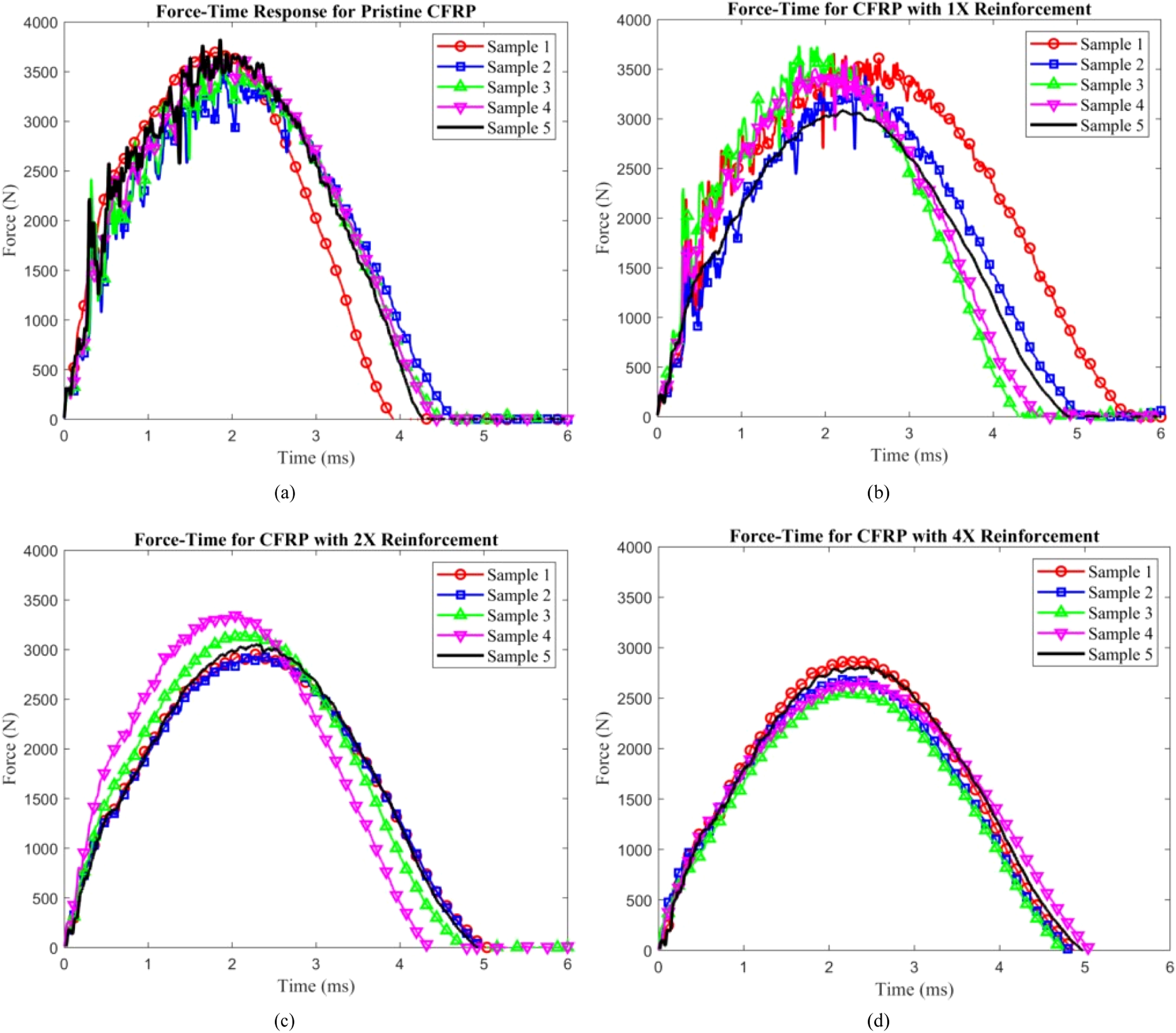
The peak force represents the maximum force recorded during the striker-laminate contact. Figure 7(a) illustrates the peak force for pristine and Aramid pulp-reinforced laminates (1X, 2X, and 4X). As shown, the pristine samples experienced the highest impact forces, while the peak force progressively decreased with increasing reinforcement, with the 4X samples exhibiting the lowest maximum impact force. This trend can be attributed to the additional reinforcement provided by the Aramid pulp, which introduces pathways for enhanced energy dissipation. Aramid fibers, known for their toughness and impact resistance, distribute energy more effectively throughout the composite, reducing stress concentration and lowering the peak impact force. Acting as an interlaminar toughening agent, Aramid pulp improves the bonding between layers by bridging gaps, enabling the impact load to be distributed over a larger area and minimizing stress at the contact point. The Aramid pulp reinforcement features a hierarchical structure of microfibers and nanofibers, uniformly and randomly dispersed between the carbon fiber layers when blended with resin. During manufacturing, the laminate is compressed between two aluminum molds, forcing the Aramid pulp fibers into the gaps between woven layers, where they intertwine with the carbon fiber bundles.
59
Under low-velocity impact (LVI) conditions, these microfibers undergo mechanisms such as pull-out, splitting, or breakage, creating a fiber-bridging effect that limits delamination growth and enhances the composite’s impact resistance.
57
These mechanisms are further detailed in the ”Damage Mechanisms” subsection. Average impact parameters as a function of reinforcement quantity: (a) maximum force, (b) impact duration time, (c) bending stiffness, (d) maximum displacement, and (e) degree of damage.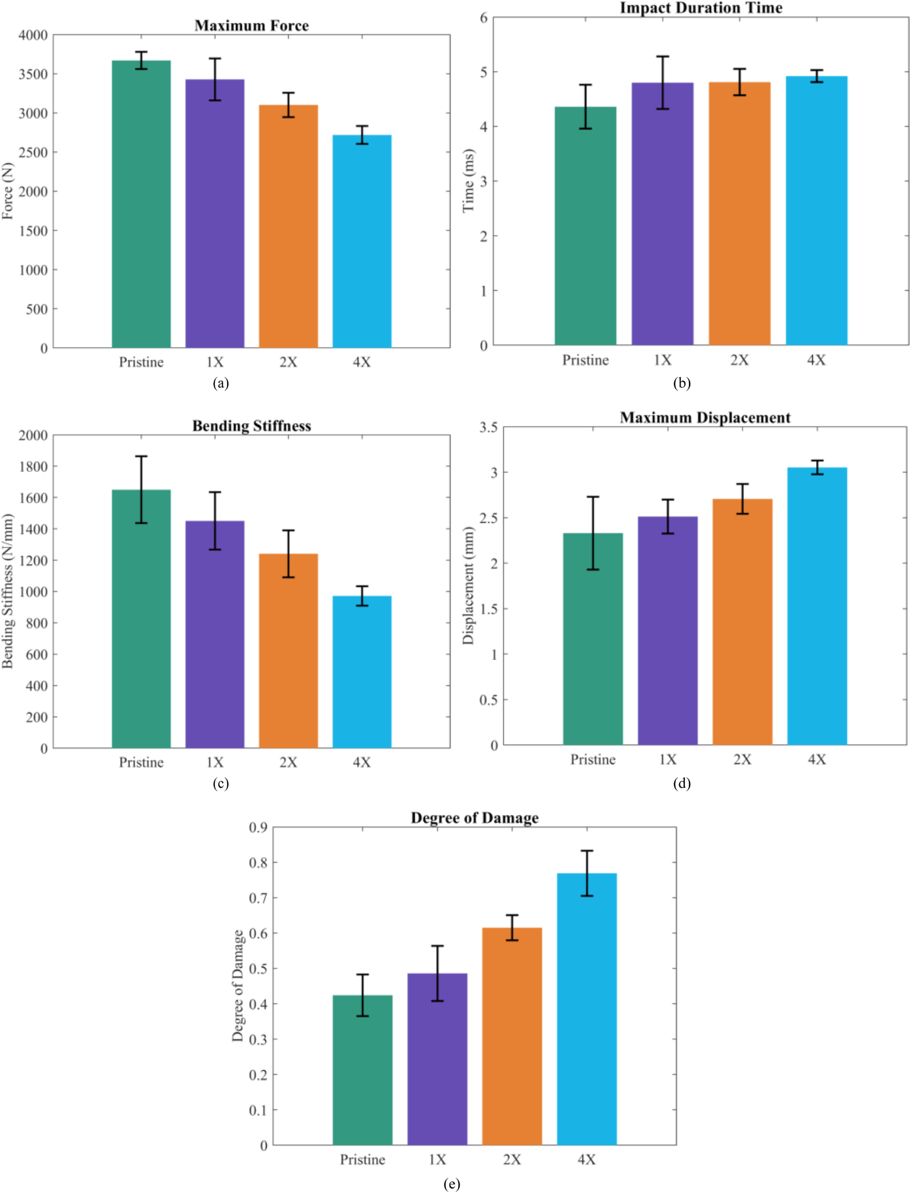
For all samples, the force decreased after reaching the peak, as the impactor began to rebound, eventually dropping to zero upon detachment from the laminate.
Figure 7(b) presents the impact duration for pristine and Aramid pulp-reinforced laminates (1X, 2X, and 4X). Among all tested specimens, the pristine samples exhibited the shortest impact durations. This behavior can be attributed to the rigidity of pristine CFRP laminates, where energy dissipation occurs primarily through matrix cracking and delamination. These mechanisms lead to a rapid energy release and, consequently, shorter impact durations.72,73 Additionally, resin matrices typically have lower fracture toughness and reduced resistance to crack initiation due to their high cross-link density. 74 In contrast, Aramid pulp-reinforced laminates (1X, 2X, and 4X) exhibited significantly longer impact durations. This can be explained by forming of a modulus transition layer, which reduces the difference in stiffness between the carbon fibers and the polymer matrix. This transition layer minimizes stress concentrations and promotes uniform stress transfer at the fiber-matrix interface. Furthermore, Aramid pulp acts as an effective toughening agent by bridging and arresting cracks, thereby slowing damage propagation and allowing the laminate to absorb energy more efficiently over an extended period. 75 Including Aramid pulp also introduces flexible interfacial layers formed by low-modulus fibers. These layers accommodate deformation under stress, reducing stress concentrations and preventing excessive buildup. 74 Kevlar pulp, being softer and less stiff than carbon fibers, softens the overall laminate structure, enabling it to deform over a longer duration under impact. This damping effect slows stress wave propagation, resulting in more gradual energy dissipation, a longer time for the force to reach its peak, and an extended return to equilibrium. Together, these mechanisms explain the increased impact durations observed in Aramid pulp-reinforced laminates compared to their pristine counterparts.
Force-displacement historie
Figure 8 presents the force- displacement graphs for CFRP laminates subjected to a 5 J impact: pristine (unreinforced) in 8(a), 1X reinforced in 8(b), 2X reinforced in 8(c), and 4X reinforced in 8(d). The area under the force-displacement curve represents the energy absorbed by the sample, as explained in more detail in the subsection “Energy-Time Histories”. In all the graphs, as the quantity of reinforcement increased, the enclosed area also increased. This indicates that the 4X reinforced samples absorbed more energy, and therefore experienced the most damage among all the tests. There was no penetration in any of the laminates. For this reason, all force-displacement graphs are seen as closed-type curves. Force-displacement graphs for CFRP laminates subjected to an impact energy of 5J: (a) Pristine, (b) 1X reinforced, (c) 2X reinforced, and (d) 4X reinforced.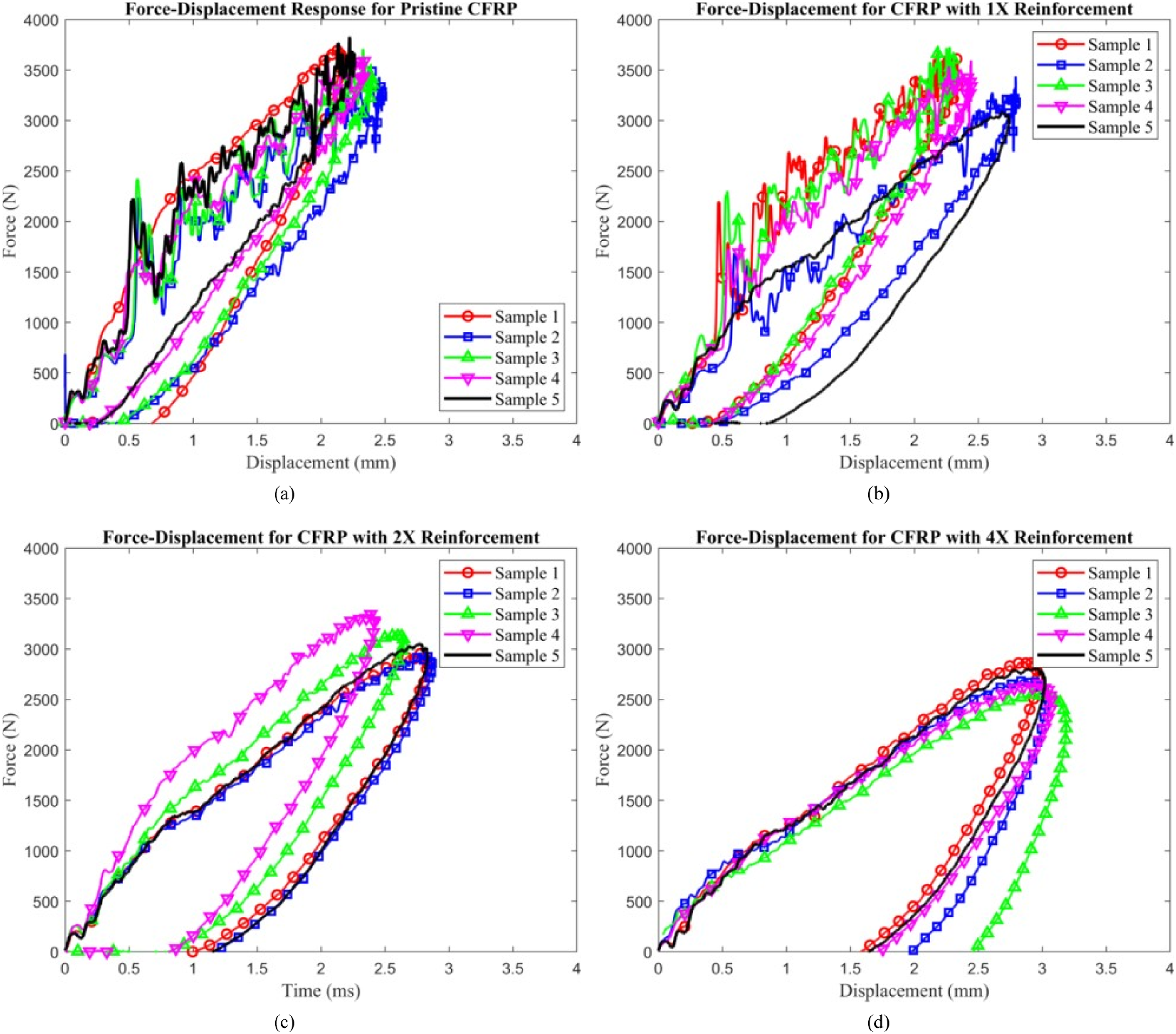
Figure 8(a) (pristine) and 8(b) (1X reinforced) exhibit oscillations in the rising section of the force-time curve, indicating the presence of damage within the samples. 76 In contrast, Figure 8(c) (2X reinforced) and 8(d) (4X reinforced) display a smooth slope in the rising section, suggesting that no significant damage occurred, as explained previously in the subsection “Force-time histories”. Despite this, the reinforced samples absorbed more energy, as evidenced by the larger enclosed area under the curve. Figure 7(c) presents the bending stiffness of pristine and Aramid pulp-reinforced laminates (1X, 2X, and 4X). As shown, the pristine samples exhibited the highest bending stiffness, while the bending stiffness decreased with increasing reinforcement, with the 4X samples showing the lowest bending stiffness. This trend can be attributed to the addition of Aramid pulp, which enhances impact resistance through energy-absorbing mechanisms such as fiber pull-out and crack bridging. However, its lower modulus compared to carbon fibers leads to a localized reduction in stiffness. The inclusion of Kevlar pulp reduces the overall stiffness of the laminate, as it does not contribute significantly to bending rigidity compared to carbon fibers. Its presence in the interlaminar regions disrupts the matrix’s structural continuity, weakening the matrix-dominated contribution to stiffness. Additionally, by targeting the interlaminar regions to improve damage tolerance, Aramid pulp interrupts the continuity of the carbon fiber layers, which primarily bear bending loads. This interruption slightly reduces the composite’s load- bearing capacity in the bending plane. While this reduction in bending stiffness is a trade-off, it allows the composite to absorb impact energy more effectively and improve damage mitigation during impact events. However, the benefits of Aramid pulp reinforcement depend on its proper dispersion within the laminate. Poor dispersion can lead to the formation of agglomerates or resin-rich pockets, which act as stress concentrators and reduce the material’s mechanical performance. These defects can compromise both bending stiffness and impact resistance, highlighting the importance of ensuring uniform reinforcement to maintain structural integrity. A detailed explanation of the damage mechanisms observed during impact is provided in the ”Damage Mechanisms” subsection. Reducing bending stiffness is necessary to optimize the laminate for enhanced energy dissipation and damage resistance under impact loading. Figure 7(d) illustrates the maximum displacement for pristine and Aramid pulp-reinforced laminates (1X, 2X, and 4X). As the amount of reinforcement increased, the maximum displacement also increased. This trend is attributed to the compliance introduced by Aramid pulp reinforcement in CFRP, which enhances the composite’s deformability. The added reinforcement enables the laminate to absorb and distribute more energy under impact by allowing greater displacement. In contrast, the stiffer, pristine CFRP resists deformation and, therefore, exhibits smaller displacements under identical impact conditions.
The reinforced composite benefits from energy-dissipating mechanisms such as fiber pull-out, crack bridging, and frictional interactions at the fiber-matrix interface, which allow it to deform more extensively before failure. This increased toughness, combined with a slight reduction in stiffness due to the reinforcement, enables the laminate to accommodate impact forces over a larger area, resulting in greater displacement. The introduction of Kevlar pulp further alters stress distribution within the composite layers. While pristine CFRP exhibits localized deformation, reinforced laminates achieve a more uniform response under impact. This flexibility increases the maximum displacement and enhances the composite’s ability to withstand impacts that could otherwise cause localized failure in unreinforced CFRP. Additionally, Kevlar pulp absorbs impact energy through deformation, contributing to the increase in overall displacement. The reduction in bending stiffness caused by the softer Kevlar pulp leads to higher deflection under the same impact force. As a result, the laminate deforms more extensively, as Kevlar pulp facilitates greater bending and energy dissipation. A detailed explanation of the damage mechanisms observed during impact is provided in the “Damage Mechanisms” subsection.
Energy-time histories
Figure 9 shows a typical energy-time graph during an LVI event. As the striker makes contact with the laminate, the energy increases rapidly, showing a linear rise at the start of the graph. Typical energy-time graph during an impact event.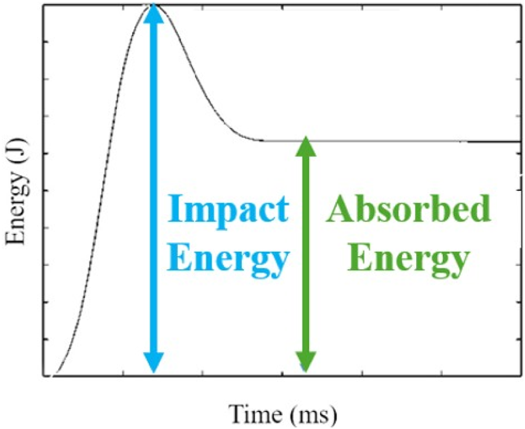
During this phase, the kinetic energy of the striker is partially converted into the specimen’s elastic potential energy, while the rest is dissipated through internal failures like matrix cracking, debonding and/or fiber fracture, and minor delaminations.77,78 The energy then peaks, corresponding to the applied impact energy (5 J). Afterward, the curve slightly decreases as the impactor rebounds and detaches from the laminate. During this phase, some energy is returned as the laminate elastically recovers. The energy curve forms a plateau in severe damage (e.g., large delaminations or fiber breakage), indicating less energy recovery. Figure 10 presents the force-energy graphs for CFRP laminates subjected to a 5 J impact: pristine (unreinforced) in 10(a), 1X reinforced in 10(b), 2X reinforced in 10(c), and 4X reinforced in 10(d). Force-energy graphs for CFRP laminates subjected to an impact energy of 5J: (a) Pristine, (b) 1X reinforced, (c) 2X reinforced, and (d) 4X reinforced.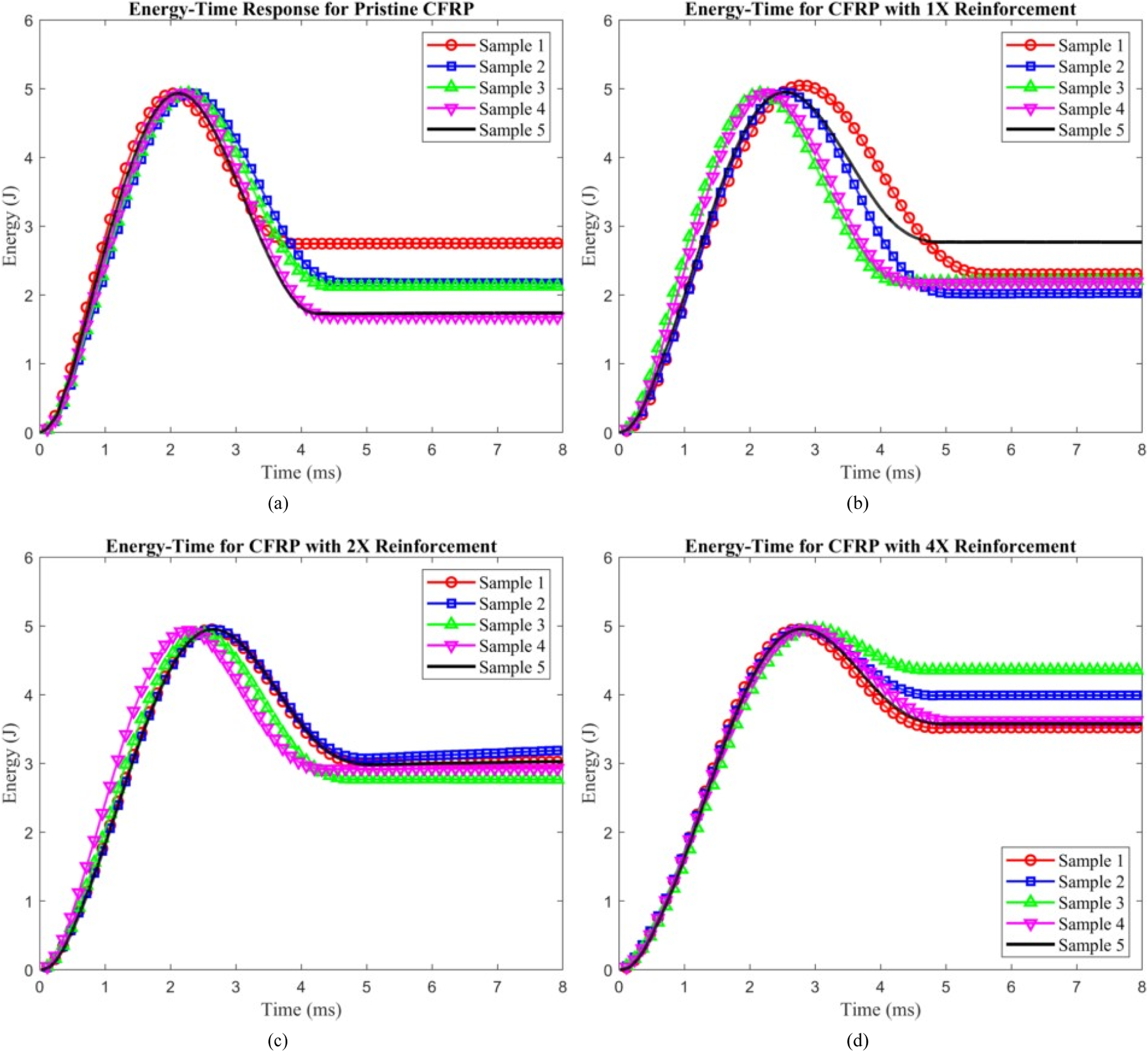
Regardless of the amount of reinforcement, all graphs (Figure 10) showed a plateau region representing the absorbed energy during impact. To assess and quantify the damage caused by an LVI event, the degree of damage (DD) was calculated using the following equation (5):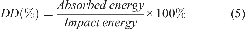
DD is defined as the ratio of absorbed energy to impact energy, as shown in Figure 9. If the impactor rebounds, the degree of damage is less than one. However, if the impactor either stops without rebounding or causes perforation of the specimen, the degree of damage is equal to one. 79
Figure 7(e) presents the degree of damage (DD) as a function of pristine and Aramid pulp-reinforced laminates (1X, 2X, and 4X). As the amount of reinforcement increased, the absorbed energy also increased, resulting in a rise in DD and indicating greater damage. During an LVI event, Aramid pulp microfibers undergo pull-out, splitting, or breaking, creating a fiber-bridging effect that dissipates energy and mitigates delamination growth. 57 However, improper dispersion of the Aramid pulp may have caused agglomeration, leading to resin-rich pockets that reduce the laminate’s strength and stiffness. A detailed discussion of the damage mechanisms observed during impact is provided in subsection ”Damage Mechanisms.” The increase in DD with higher reinforcement levels can be attributed to structural changes introduced by the additional Aramid pulp. As reinforcement quantity rises, the continuity of the matrix material diminishes, disrupting its ability to distribute stress uniformly across the composite. This disruption creates more fiber-matrix interfaces, which act as weak points where damage mechanisms—such as debonding, matrix cracking, and delamination—are more likely to initiate and propagate. Furthermore, the increased reinforcement results in higher stress concentrations around the Aramid pulp, contributing to localized damage, including fiber pull-out and crack formation. While mechanisms like fiber pull-out and crack bridging enhance energy absorption, they also lead to more extensive internal disruptions, leaving the composite more damaged after impact. The added reinforcement increases the composite’s compliance, allowing greater deformation under impact. This increased deformability dissipates more energy but also broadens the damage area, further contributing to the rise in DD. Moreover, excessive Kevlar pulp content diminishes the ability of carbon fibers to carry the load effectively. The resulting interlaminar damage, such as delamination, reduces the laminate’s overall resistance to further damage. While Kevlar pulp improves energy absorption and damage tolerance, excessive reinforcement compromises damage resistance. This tradeoff explains the observed increase in DD as the reinforcement ratio increases.
Statistical evaluation of reinforcement effects on the impact parameters using ANOVA and Tukey’s Honest Significant Difference (HSD)
ANOVA results for the average impact response parameters across reinforcement levels.
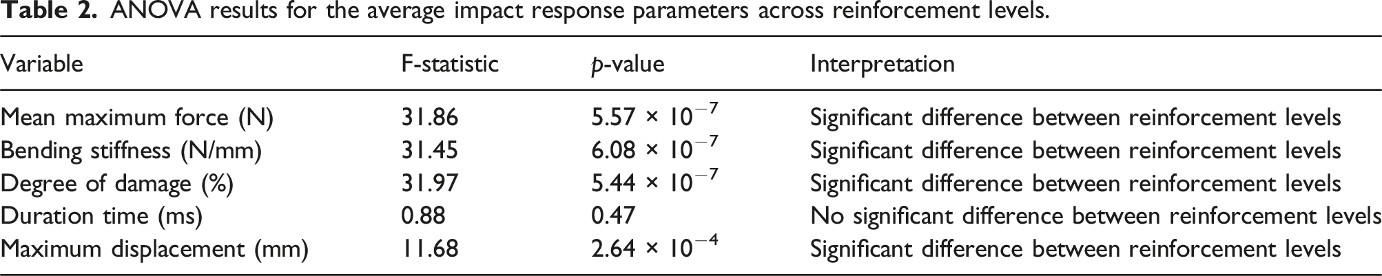
The key metric for statistical significance is the p-value, where p < .05 indicates a significant difference between at least two groups, while p ≥ .05 suggests no significant difference.
Following the ANOVA analysis, Tukey’s Honest Signif- icant Difference (HSD) test was performed to investigate the statistical differences across reinforcement levels further. This test identifies which specific reinforcement levels (Pris- tine, 1X, 2X, and 4X) exhibit significant differences for each impact parameter property. The tables presenting the results of Tukey’s HSD tests can be found in the Supplementary Material section.
Maximum force
Supplement Material Table S1 presents the results of Tukey’s HSD test for maximum force. The analysis revealed significant differences among all reinforcement levels, except between Pristine and 1X reinforcement (p = .089). Notably, 4X reinforcement exhibited the lowest maximum force, confirming that increasing reinforcement reduces peak load capacity. The most pronounced difference was observed between 4X reinforcement and Pristine (p < .001), indicating a significant reduction in maximum force with higher reinforcement content.
Impact duration time
Supplement Material Table S2 presents the results of Tukey’s HSD test for impact duration time. Unlike the other properties, Tukey’s HSD did not reveal significant differences in impact duration across most reinforcement levels. The only statistically significant comparisons were Pristine versus 1X (p = .007) and Pristine versus 2X (p = .048), indicating that early-stage reinforcement slightly affects impact duration. However, comparisons among reinforced samples (1X, 2X, and 4X) showed no significant differences (p > .05), suggesting that reinforcement does not strongly influence impact time.
Bending stiffness (N/mm)
Supplement Material Table S3 presents the results of Tukey’s HSD test for bending stiffness. Similar to maximum force, all reinforcement levels except 1X versus 2X and 2X versus 4X showed statistically significant differences. The results indicate a progressive reduction in bending stiffness with higher reinforcement levels, with Pristine versus 4X reinforcement showing the most significant decline (p < .001). These findings suggest that while reinforcement improves impact resistance, it reduces the structural rigidity of the composite.
Maximum displacement (mm)
Supplement Material Table S4 presents the results of Tukey’s HSD test for maxi- mum displacement. Tukey’s HSD analysis for maximum displacement showed significant differences for most rein- forcement levels. The Pristine versus 4X comparison (p < .001) exhibited the highest statistical significance, confirm- ing that higher reinforcement levels increase displacement and energy absorption. 1X versus 2X reinforcement (p = .177) was not statistically different, suggesting that intermediate reinforcement levels similarly affect displacement.
Degree of damage
Supplement Material Table S5 presents the results of Tukey’s HSD test for degree of damage. A clear trend was observed in the degree of damage, where Pristine samples had significantly higher damage compared to reinforced samples. Tukey’s test confirmed that Pristine versus 2X (p < .001) and Pristine versus 4X (p < .001) had the most notable reductions in damage, reinforcing the idea that higher reinforcement improves damage tolerance. Interestingly, 1X versus Pristine (p = .481) did not show a significant difference, suggesting that a minimal reinforcement level does not considerably affect damage mitigation.
Flexural response
Figure 11 presents the stress-strain graphs for CFRP laminates subjected to a 5 J impact: pristine (unreinforced) in 11(a), 1X reinforced in 11(b), 2X reinforced in 11(c), and 4X reinforced in 11(d). Flexural tests were conducted following ASTM D790-17 standards, and specimens were tested until either failure occurred or the 5% flexural strain limit was reached. For pristine samples, testing was stopped at the 5% strain limit as no failure occurred; the specimens returned to their original positions post-testing. In contrast, all reinforced samples exhibited failure before reaching the 5% flexural strain limit. Each graph begins with a linear elastic region, from which the flexural modulus was calculated. Flexural stress-strain graphs for resin samples: (a) Pristine, (b) 1X reinforced, (c) 2X reinforced, and (d) 4X reinforced.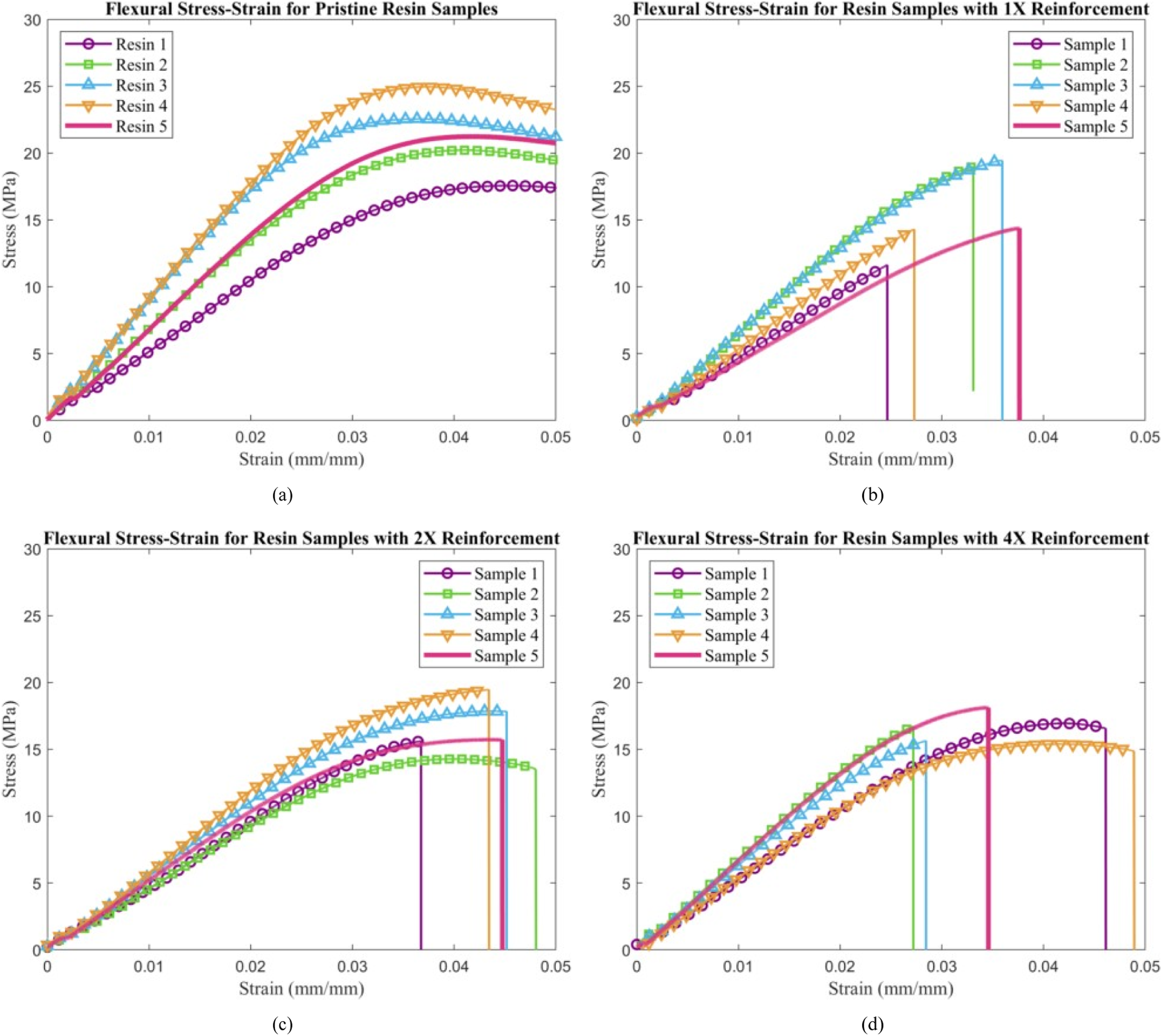
Flexural stiffness
Figure 12(a) illustrates the flexural stiffness of pristine and Aramid pulp-reinforced resin samples (1X, 2X, and 4X). The pristine samples exhibited the highest flexural stiffness, while the reinforced samples showed a noticeable reduction in stiffness, with all reinforced samples displaying similar values. This reduction in flexural stiffness with increasing reinforcement can be attributed to several factors related to the interaction between Aramid pulp and the resin matrix. Aramid pulp fibers, with their smooth surfaces and lack of functional bonding groups,
80
often exhibit limited adhesion to standard resin matrices. This weak fiber-matrix interface results in inefficient load transfer, leading to reduced stiffness compared to pristine resin, where stress is distributed uniformly. Furthermore, the addition of Aramid pulp disrupts the continuity of the matrix, creating localized areas of weakness. Poor dispersion of fibers can lead to resin-rich zones around the pulp, which are prone to bending and further diminish stiffness. Misaligned or unevenly distributed fibers fail to contribute effectively to stiffness under flexural loads, while the ends of Aramid fibers may act as stress concentrators, initiating premature failure. Finally, the inherent flexibility and lower modulus of Aramid fibers compared to the resin matrix further reduce resistance to flexural loads, diminishing the overall stiffness of the composite. The flexural test results align closely with the trends observed in the impact tests, providing further insight into the fundamental changes in the mechanical behavior of the composite due to the addition of Aramid pulp. The reduction in flexural stiffness observed in resin samples with increasing reinforcement correlates with the lower bending stiffness and higher displacement reported in the impact tests for reinforced CFRP laminates. These findings confirm that the addition of Aramid pulp introduces compliance into the composite, reducing its stiffness while enhancing its ability to deform and absorb energy. The weak adhesion between Aramid pulp fibers and the resin matrix, as indicated by the flexural results, explains the reduced load transfer efficiency and matrix continuity, which lead to localized stress concentrations. These characteristics align with the observed increase in displacement and damage during impact testing, as the interlaminar regions become less cohesive and more prone to deformation. Additionally, the flexibility and lower modulus of Aramid pulp compared to carbon fibers or pristine resin contribute to the laminate’s ability to dissipate energy during impact, albeit at the expense of stiffness and strength. Average flexural parameters as a function of reinforcement quantity: (a) flexural stiffness, (b) flexural yield strength, (c) flexural stiffness, and (d) failure strain.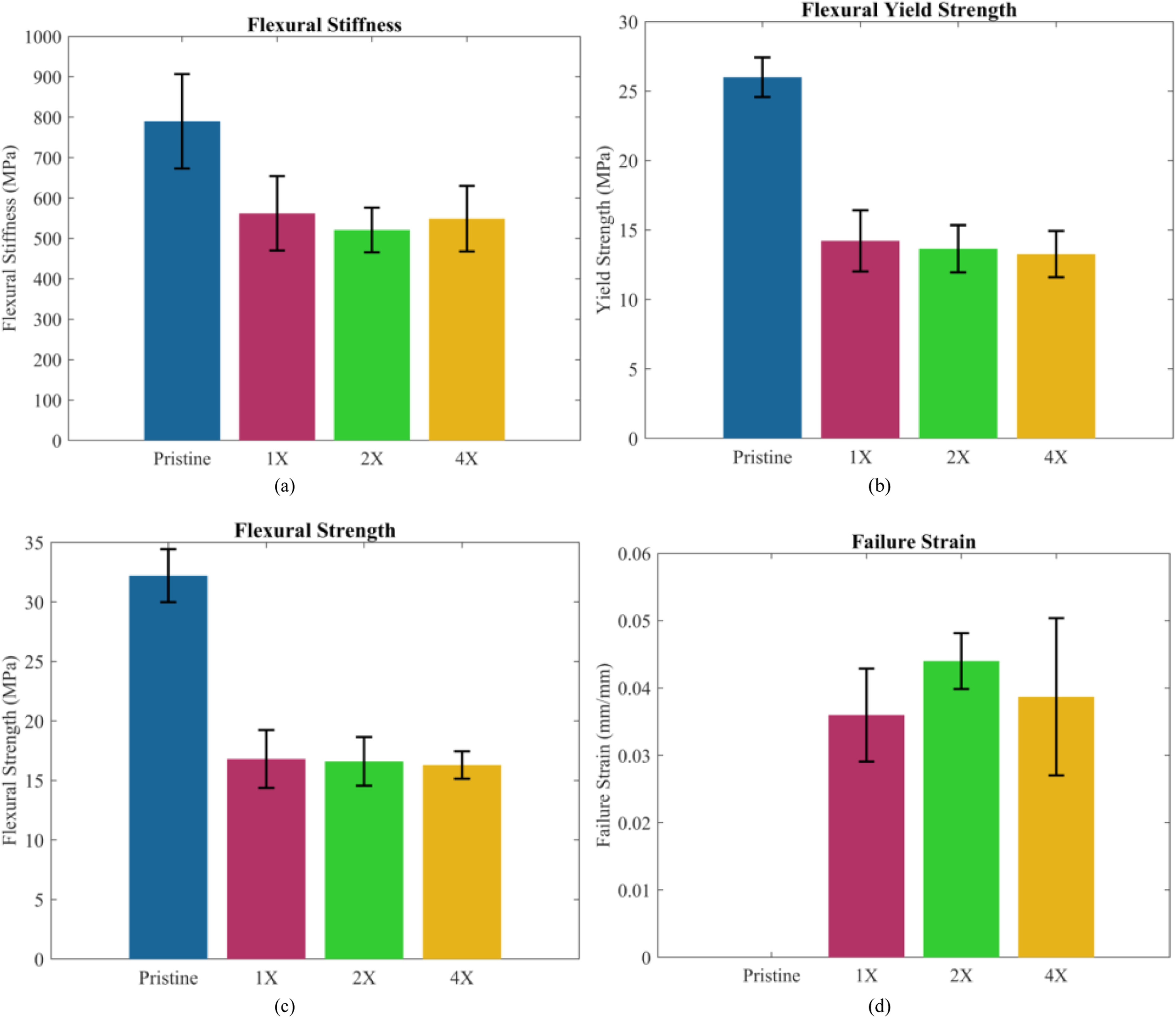
Flexural stiffness and yield strength
The flexural yield strength, defined as the stress corresponding to a strain exceeding the proportional region of the stress-strain curve by 0.1%, is presented in Figure 12(b) for pristine and Aramid pulp-reinforced resin samples (1X, 2X, and 4X). Similarly, the flexural strength, representing the maximum stress achieved during testing, is shown in Figure 12(c). Both yield strength and flexural strength decreased with increasing Aramid pulp reinforcement, highlighting key changes in the composite’s mechanical behavior. This reduction can be attributed to several factors. Weak adhesion between the Aramid pulp fibers and the resin matrix, due to the fibers’ smooth surfaces and lack of functional bonding groups, results in poor load transfer, diminishing the composite’s ability to bear flexural loads effectively. Furthermore, introducing Aramid pulp disrupts the matrix’s continuity, ensuring uniform stress distribution in pristine resin. This disruption leads to regions of inefficient load transfer and localized stress concentrations that weaken the composite. Poor dispersion of the fibers further exacerbates this issue, forming resin-rich zones that lack reinforcement and are more prone to deformation or failure. The inherent flexibility and lower modulus of Aramid fibers compared to the resin matrix also play a significant role, as they provide less resistance to flexural loads, reducing overall strength. Additionally, the ends of the Aramid fibers can act as stress concentrators, initiating cracks or fractures under flexural loading. Interfacial debonding between the fibers and the matrix further undermines the reinforcement’s effectiveness, resulting in premature failure and reduced yield and flexural strength. The results from the flexural tests strongly support the findings from the impact tests, revealing how increasing Aramid pulp reinforcement affects the composite’s mechanical performance. The decrease in flexural yield and maximum strength aligns with the reduction in bending stiffness observed during impact tests. This is consistent with the weak adhesion and localized stress concentrations that reduce load transfer efficiency, explaining the composite’s diminished ability to resist impact forces. The disrupted matrix continuity and inefficient load transfer contribute to lower stiffness and greater displacement under impact conditions. Additionally, the flexibility and lower modulus of Aramid fibers, which reduce flexural strength in resin-only samples, play a similar role in impact performance. These properties increase the material’s compliance, allowing for greater deformation and energy absorption simultaneously weakens structural integrity, making the composite more susceptible to damage mechanisms such as delamination and matrix cracking. The formation of resin-rich zones and stress concentrators observed in flexural testing further supports the increased damage noted in the impact tests. Poor fiber dispersion and interfacial debonding exacerbate these effects, resulting in a less cohesive laminate that is more prone to damage under impact. Together, the flexural test results provide valuable insights into the trade-off between enhanced energy absorption and reduced structural performance, reinforcing the trends observed in the impact tests.
Flexural strain
The flexural failure strain, defined as the strain at which failure occurs, is presented in Figure 12(d) for pristine and Aramid pulp-reinforced resin samples (1X, 2X, and 4X). The pristine resin samples did not fail, reaching the 5% strain limit without fracturing; therefore, failure strain was not calculated for these samples. The 2X reinforcement exhibited the largest failure strain among the reinforced samples, while the 1X and 4X samples showed increased strain compared to pristine resin. The increased flexural strain in Aramid pulp-reinforced samples highlights the enhanced deformability introduced by the pulp. Aramid fibers, being inherently more flexible and ductile than the resin matrix, allow for greater strain before failure. The 2X reinforcement’s superior performance in terms of failure strain suggests an optimal balance between fiber content and matrix continuity. At this reinforcement level, the Aramid pulp fibers effectively bridge cracks and absorb deformation energy without significantly disrupting the matrix structure. This crack-bridging mechanism, a characteristic behavior of Aramid pulp, delays the onset of catastrophic failure, allowing the composite to sustain higher strains. However, the strain behavior observed in the 1X and 4X reinforced samples reflects the complex interplay between fiber- matrix interactions and reinforcement distribution. In the 1X samples, the relatively low fiber content may limit the extent of crack bridging and energy absorption, resulting in a smaller increase in strain compared to the 2X samples. Conversely, in the 4X samples, the higher fiber content may lead to poor dispersion and the formation of resin-rich zones, which disrupt the matrix’s uniformity and create stress concentrators. These zones reduce the reinforcement’s efficiency in distributing and absorbing stress, ultimately limiting the failure strain. Moreover, the smooth surface and lack of functional bonding groups on Aramid pulp fibers contribute to weak fiber-matrix adhesion, particularly at higher reinforcement ratios. This weak interface hinders effective load transfer between the resin and fibers, exacerbating localized stress concentrations and making the material more prone to microcracking or premature failure. At the same time, the inherent compliance of Aramid pulp reduces the matrix’s rigidity, enabling the material to deform more extensively under flexural loads. While this compliance increases the failure strain, it comes at the cost of reduced stiffness and strength. The 2X reinforcement level’s superior failure strain performance indicates that an intermediate amount of reinforcement maximizes the benefits of crack bridging and energy absorption while minimizing the adverse effects of fiber agglomeration and stress concentration. These findings underscore the importance of optimizing the reinforcement ratio to achieve a balance between ductility, energy dissipation, and mechanical performance in Aramid pulp-reinforced composites.
Fracture surface analysis of aramid pulp-reinforced specimens
Figure 13 presents representative SEM micrographs of the fractured surfaces of flexural samples for Aramid pulp- reinforced composites (1X, 2X, and 4X). Since the pristine samples did not fail, their fracture surfaces could not be analyzed. Figure 13(a) shows the fracture surface of 1X specimens, highlighting the effects of Aramid Pulp addition on resin fracture behavior. The incorporation of Aramid Pulp results in a rougher fracture surface and promotes the formation of crazes along the crack plane, a phenomenon typically absent in pristine epoxy. These crazes act as toughening mechanisms, enhancing the material’s ability to dissipate energy and resist crack propagation.
81
Figure 13(b) presents the fracture surface of 2X specimens, revealing a rougher surface texture along with fiber pullout as a prominent failure mechanism. The increased fiber pullout observed in these specimens is attributed to the higher Aramid Pulp content, which weakens fiber-matrix adhesion and promotes debonding during fracture. Figure 13(c) presents the fracture surface of 4X specimens, showing more pronounced fiber pullout and fiber clustering compared to lower reinforcement levels. The presence of larger fiber clusters suggests increased fiber agglomeration, which can lead to heterogeneous reinforcement distribution within the matrix. This non-uniform dispersion contributes to localized stress concentrations that influence crack propagation and fracture behavior. Additionally, the higher Aramid Pulp content in the 4X specimens leads to an increase in void formation, as excessive reinforcement hinders proper resin infiltration and curing. These voids act as weak points within the material, reducing load transfer efficiency between the fibers and the matrix. As a result, fiber-matrix debonding becomes more prevalent, promoting fiber pullout as a dominant failure mechanism. The combination of fiber pullout, void formation, and clustering results in a more tortuous fracture path, increasing energy absorption but also compromising overall structural integrity. Representative SEM micrographs of the fractured surfaces of Aramid pulp-reinforced specimens at different reinforcement levels: (a) 1X, (b) 2X, and (c) 4X.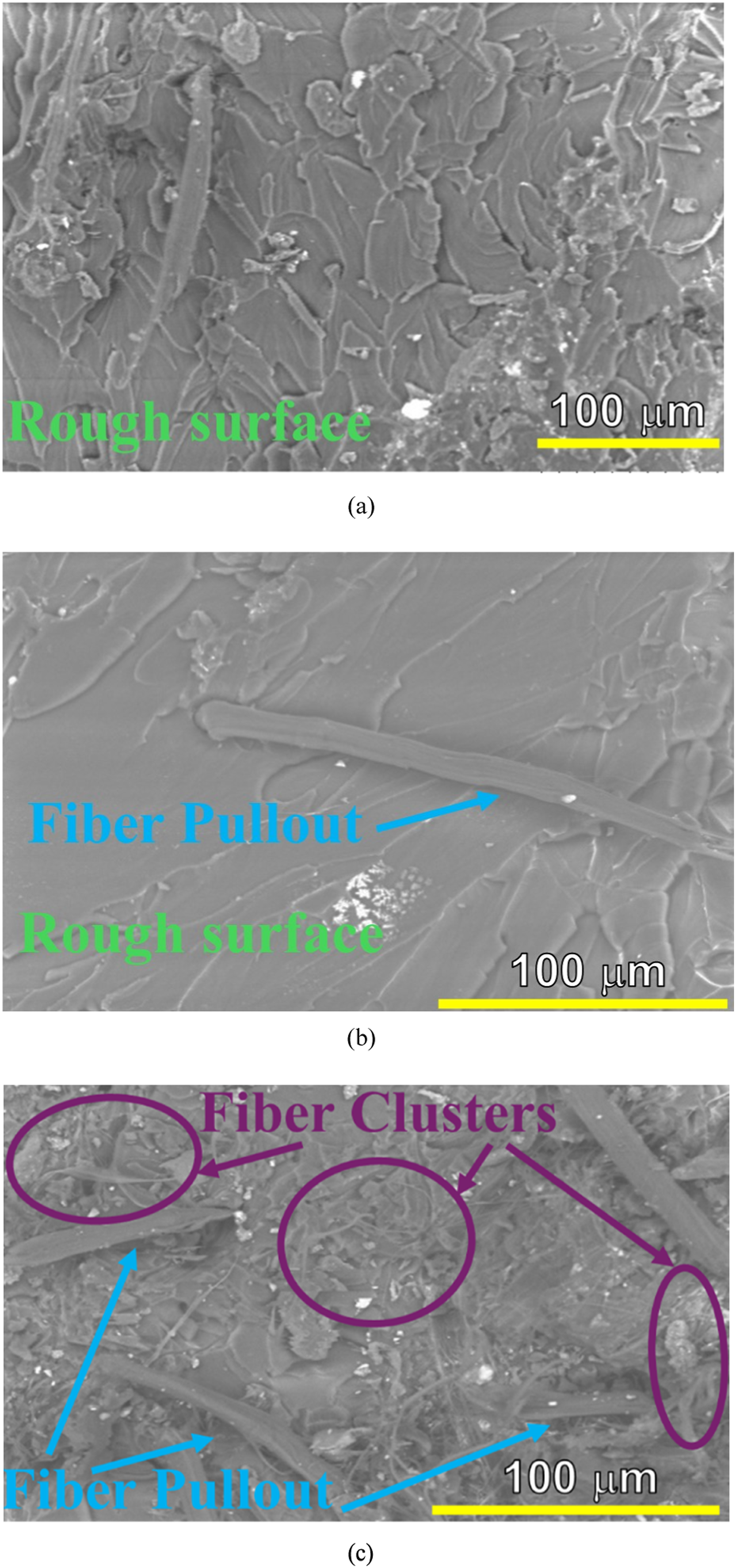
Statistical evaluation of reinforcement effects on the Flexural Properties using ANOVA and Tukey’s Honest Significant Difference (HSD)
Statistical analysis of flexural properties.
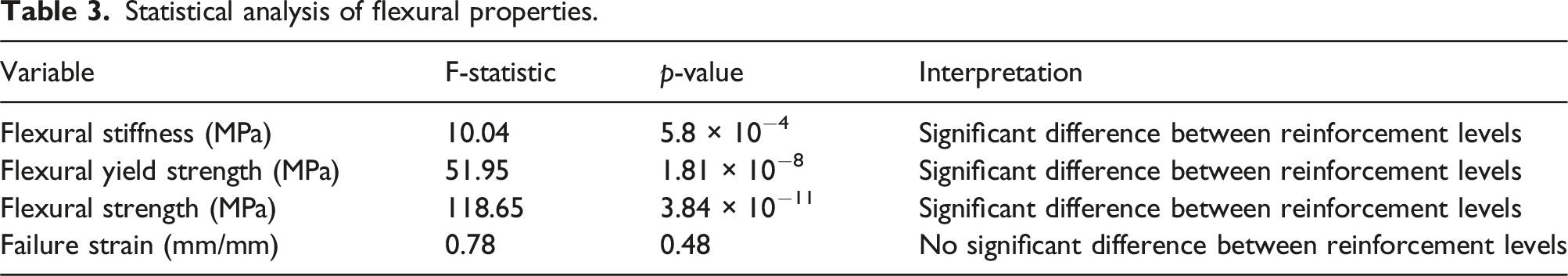
Tukey’s Honest Significant Difference (HSD) test was conducted following the ANOVA analysis to examine the statistical differences between reinforcement levels further. This test determines which specific reinforcement levels (Pristine, 1X, 2X, and 4X) exhibit significant differences for each flexural property. The results of Tukey’s HSD tests are provided in the Supplementary Material section.
Flexural stiffness
Supplement Material Table S6 presents the results of Tukey’s HSD test for flexural stiffness. Tukey’s HSD test revealed significant differences between pristine and all reinforced samples (p < .05). However, comparisons between 1X and 2X as well as 1X and 4X showed no significant differences (p > .05). These results indicate that Pristine samples exhibit significantly higher flexural stiffness compared to reinforced samples. However, 1X, 2X, and 4X reinforcement levels do not show statistically significant differences among each other, suggesting that stiffness reduction occurs primarily upon the introduction of reinforcement but does not change substantially with increasing reinforcement levels.
Flexural Yield Strength
Supplement Material Table S7 presents the results of Tukey’s HSD test for flexural yield strength. Tukey’s HSD test revealed highly significant differences between pristine and all reinforced samples (p < .001), indicating that reinforcement has a strong effect on reducing flexural yield strength. However, comparisons between 1X, 2X, and 4X reinforcement levels showed no statistically significant differences (p > .05). These results suggest that Pristine samples exhibit significantly higher yield strength than reinforced samples. However, once reinforcement is introduced, further increasing its quantity does not substantially impact flexural yield strength.
Flexural strength
Supplement Material Table S8 presents the results of Tukey’s HSD test for flexural yield strength. Tukey’s HSD test indicated highly significant differences between pristine and all reinforced samples (p < .001), confirming that reinforcement significantly reduces flexural strength. However, no significant differences were observed between 1X, 2X, and 4X reinforcement levels (p > .05). These results demonstrate that pristine samples exhibit significantly higher flexural strength compared to reinforced samples. Like yield strength, increasing the reinforcement level beyond 1X does not result in further statistically significant reductions in flexural strength.
Failure Strain
Supplement Material Table S9 presents the results of Tukey’s HSD test for flexural yield strength. Tukey’s HSD test revealed no significant differences in failure strain between any reinforcement levels (p > .05), indicating that reinforcement does not have a statistically measurable effect on this property. These results suggest that failure strain remains statistically unchanged across all reinforcement levels, implying that reinforcement does not strongly influence the material’s deformation capacity before failure.
Damage mechanisms
Visual inspection
A visual inspection of the impacted laminates revealed no penetration in any of the samples, consistent with the relatively low impact energy levels used in this study. This observation is further supported by the closed force-displacement curves (Figure 6) recorded at all tested impact energies. Figure 14 presents the representative front (impacted) and back faces of both reinforced and pristine laminates subjected to a 5 J impact. In the pristine and 1X reinforced samples, matrix cracking is clearly visible on the front face at the impact site. These cracks propagated along the fiber direction and, due to the woven structure of the laminate, formed a distinctive cross-pattern, as shown in Figure 14. No damage was observed on the back face of these laminates, which is attributed to the low LVI energy of 5 J, chosen to induce internal damage with minimal surface disruption. The 1X reinforced samples exhibited front-face damage with a smaller cross-pattern matrix crack compared to the pristine samples. This reduction in damage severity is attributed to the fiber-bridging effect of the Aramid fibers, which effectively mitigated crack propagation and localized stress concentrations. Similar to the pristine samples, no damage was observed on the back face of the 1X reinforced laminates, further highlighting the role of reinforcement in confining damage to the front face. In contrast, no visible surface damage was evident for the 2X and 4X reinforced samples. This is likely due to the masking effect of the Aramid pulp. In the pristine and 1X reinforced samples, the black carbon fibers provided a stark contrast against the white matrix cracks, making them easily distinguishable. However, in the 2X and 4X reinforced samples, the increased amount of yellowish-white Aramid pulp obscured the visibility of surface cracks, as any white cracks were less distinguishable from the surrounding reinforcement. Additionally, in the 4X reinforced samples, agglomerations of Aramid pulp were observed on the surface, further complicating visual detection of matrix cracks. Despite the lack of visible damage on the surfaces of the 2X and 4X reinforced samples, no damage was observed on the back faces of these laminates. To investigate the internal damage mechanisms more thoroughly, micro-CT scans were performed to gain better insight into the damage inside the laminates. Front face and back face of CFRP laminates impacted at 5J for pristine, 1X reinforced, 2X reinforced, and 4X reinforced samples.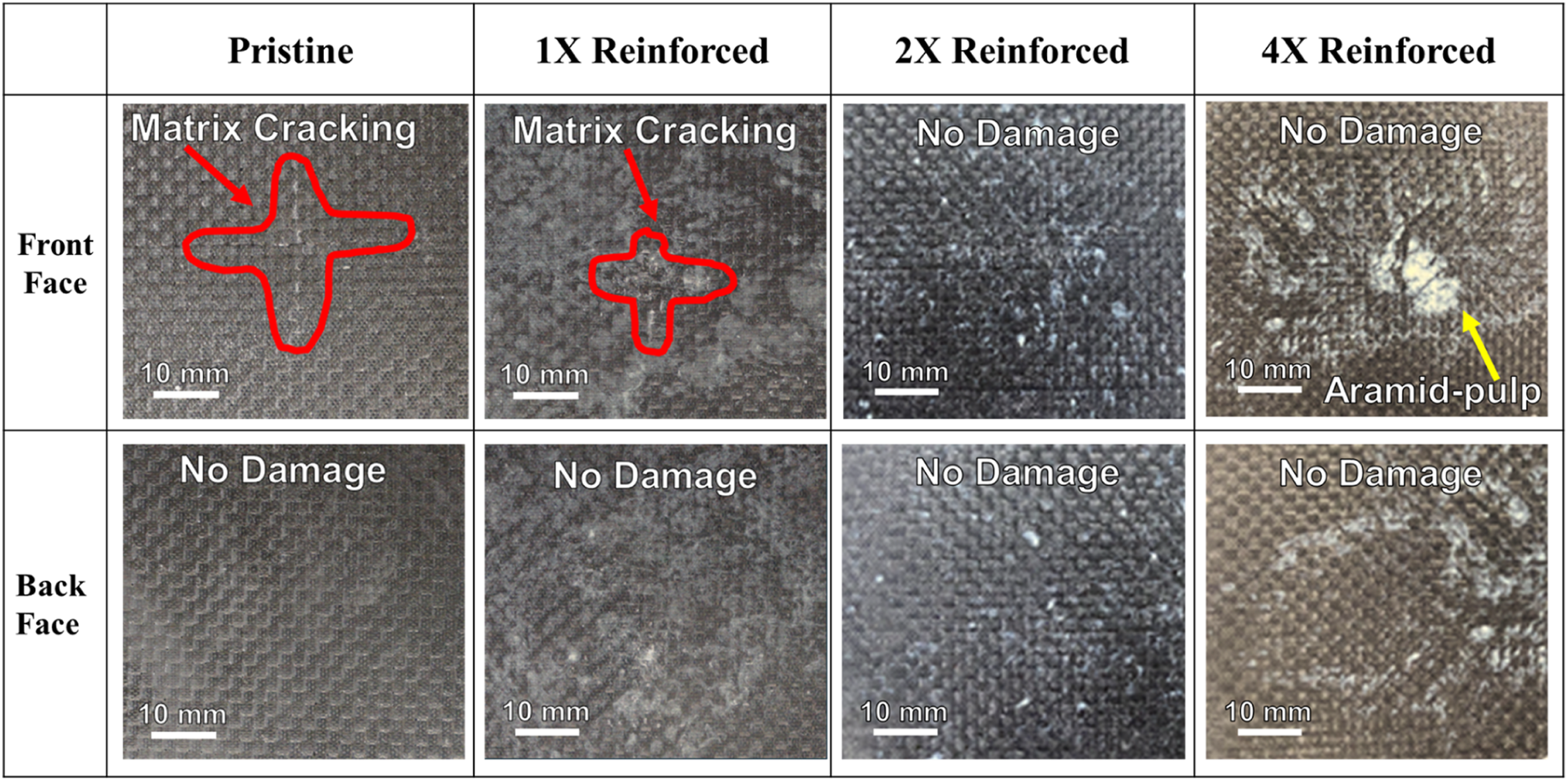
Ray micro-CT scans
X-ray micro-CT scans were conducted to examine the internal damage mechanisms resulting from the LVI event in both unreinforced and Aramid pulp-reinforced samples. Figure 15 presents the through-the-thickness view used for characterization, with the impacted zone highlighted by a red circle, consistently centered in each view. Figure 16 presents through-the- thickness micro-CT scans of samples impacted at 5 J: pristine (unreinforced) in Figure 16, 1X reinforced in Figure 16(b), 2X reinforced in Figure 16(c), and 4X reinforced in Figure 16(d). In the unreinforced sample (Figure 16(a)), the primary failure mechanism observed is delamination, highlighted by the yellow ellipsoid in the image. Additionally, voids within the laminate are visible and marked by the dotted green ellipsoid. Overall, the primary failure mechanism in the unreinforced sample is delamination, concentrated near the laminate’s impact zone (front face). Toward the bottom of the micro-CT scan, no damage is observed, except for an air void, indicating that the damage is primarily localized to the area near the impact site. In the 1X Aramid pulp-reinforced sample (Figure 16(b)), delamination is more evident near the impacted face, as highlighted by the yellow ellipsoid. The delaminations are larger compared to the unreinforced samples. Some air voids are also in the laminate, marked by the dotted green ellipsoid. For the 2X Aramid pulp-reinforced sample (Figure 16(c)), even greater delamination is observed near the impact face (top part of the laminate), highlighted by the yellow ellipsoid. The delaminations are larger and more prominent than the unreinforced and 1X reinforced samples. Moreover, the laminate contains more air voids throughout the thickness than the previous samples. This increase in voids is attributed to the higher reinforcement content, where excessive Aramid pulp led to agglomeration, creating air pockets. These voids reduced the laminate’s stiffness, causing it to experience lower impact forces and making it less stiff than the unreinforced and 1X reinforced samples. In this case, the air voids are not individually highlighted with green ellipsoids, as the increased presence of voids is visually apparent. View used for internal damage characterization. Through-the-thickness view of impacted samples at 5 J: (a) pristine, (b) 1X Reinforced, (c) 2X Reinforced, and (d) 4X Reinforced.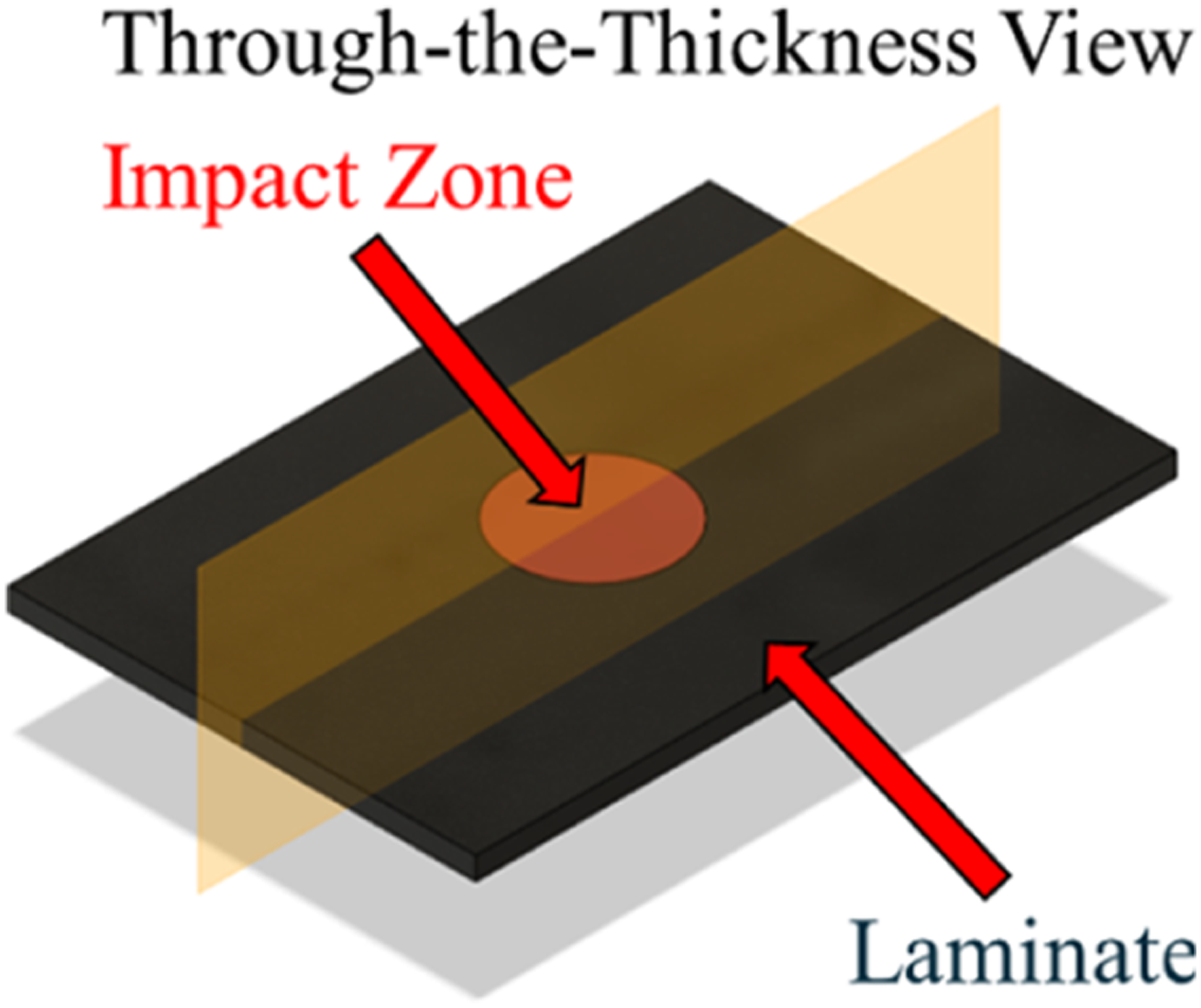
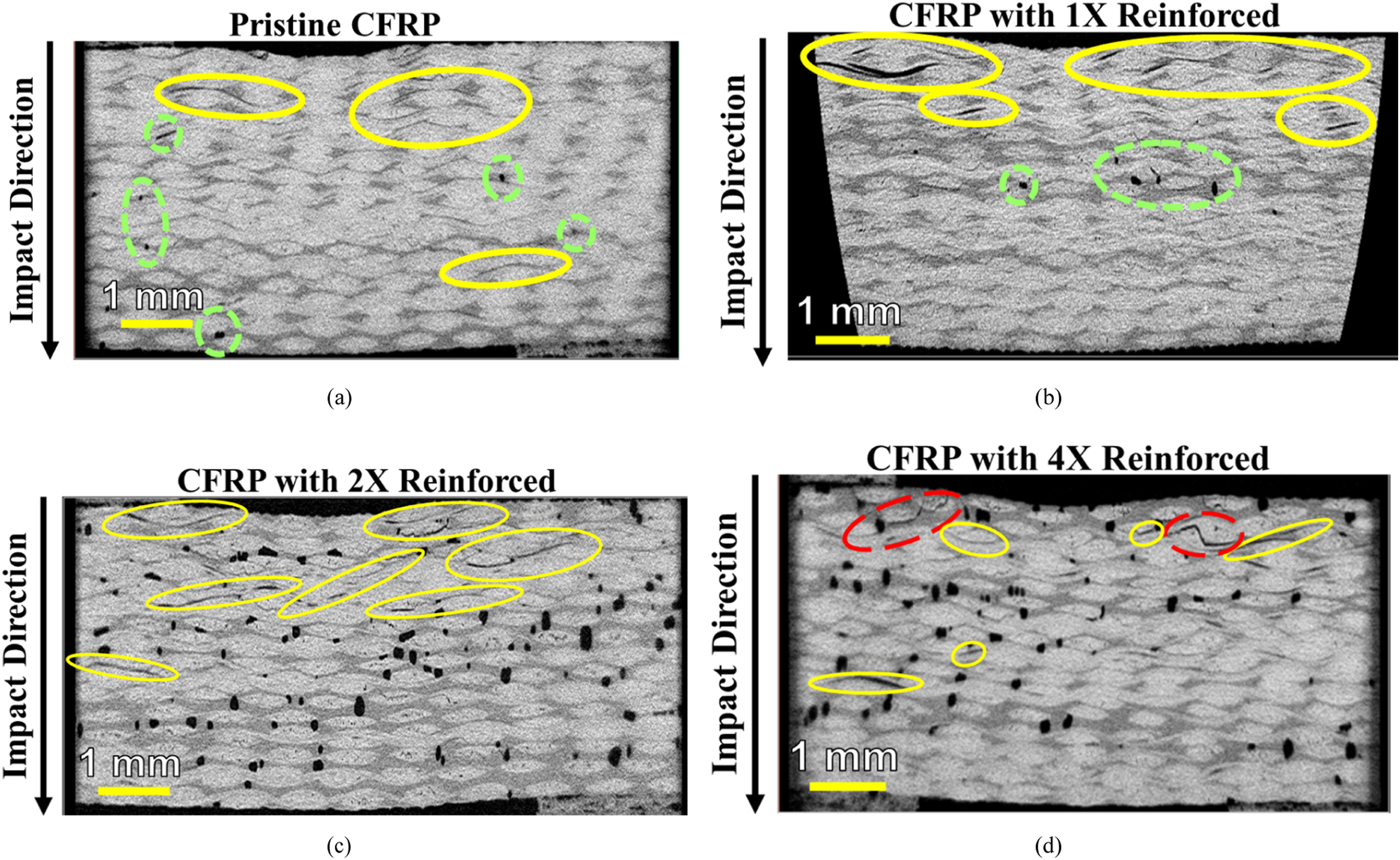
In the 4X reinforced samples (Figure 16(d)), delamination occurs not only near the impacted face but also extends toward the back of the laminate, indicating a more extensive damage distribution. A higher presence of air voids is also observed, further weakening the composite. Beyond these failure mechanisms, intralaminar cracking, a unique feature of the 4X reinforced samples, is also present. It is hypothesized that the significant agglomeration of reinforcement creates localized stiffness variations, forcing cracks to bifurcate and propagate as intralaminar damage. The presence of extensive delamination and voids significantly reduces the stiffness and structural integrity of the composite. As delaminations grow, they act as stress concentrators, limiting the laminate’s load-bearing capacity and resulting in a lower peak force during impact testing. This explains why the peak force recorded for the 4X reinforced samples is lower than that of the pristine, 1X, and 2X reinforced samples. Additionally, the increased damage degree in the 4X reinforced samples can be attributed to the combined effects of delamination, intralaminar cracking, and void-induced stress redistribution. The presence of intralaminar failure suggests a shift in the dominant failure mode, from purely interlaminar delamination to a combination of interlaminar and intralaminar damage. This transition indicates that rather than improving toughness, the reinforcement has led to unintended stress redistribution, promoting further crack propagation. Furthermore, the increased porosity due to Aramid pulp agglomeration contributes to reduced stiffness and mechanical integrity. The formation of voids weakens the material by disrupting load transfer between fibers and the matrix, leading to premature failure under impact loading conditions. This trend aligns with the mechanical test results, where the 4X reinforced samples exhibit reduced impact resistance and increased damage accumulation compared to the samples with lower reinforcement content. The excessive reinforcement in the 4X samples results in multiple competing damage mechanisms, delamination, void formation, and intralaminar failure, which collectively degrade mechanical performance, reducing peak force and increasing damage degree. These findings emphasize the need to optimize reinforcement distribution to mitigate these detrimental effects while preserving the benefits of Aramid pulp reinforcement.
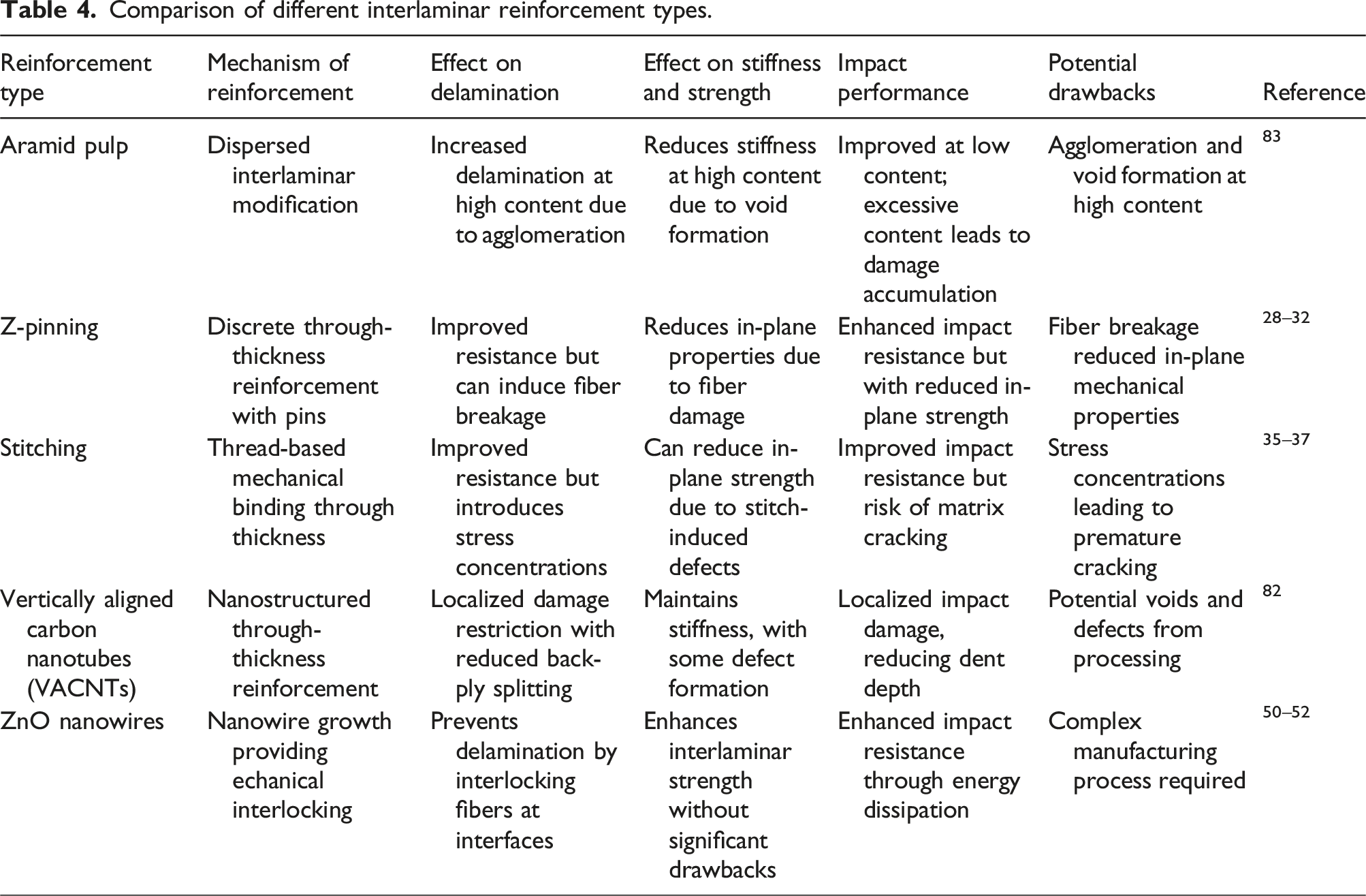
Comparison of aramid pulp reinforcement with other interlaminar toughening strategies
Comparison of different interlaminar reinforcement types.
Conclusion
This study investigates the effects of varying Aramid pulp reinforcement ratios on the impact response and damage tolerance of CFRP composites subjected to low-velocity impact (LVI). Drop-weight impact tests were conducted on pristine (unreinforced) and reinforced samples with 1X, 2X, and 4X Aramid pulp reinforcement ratios at an impact energy of 5 J. Flexural tests and micro-CT scans provided further insights into the mechanical behavior and internal damage mechanisms. The key findings are as follows:
Impact performance
(i) Peak Force: Decreases with increasing reinforcement due to the improved distribution of impact loads via delamination and matrix cracking, reducing stress concentrations. (ii) Maximum Displacement: Increases with reinforcement, reflecting the enhanced compliance and deformability introduced by Aramid pulp. (iii) Energy Absorption and Degree of Damage (DD): 4X reinforced samples absorbed the most energy but also exhibited the most significant internal damage, including delamination, void formation, and intralaminar failure.
Flexural behavior
(i) Flexural Stiffness: Decreases with reinforcement due to weak fiber-matrix adhesion and the formation of resin-rich zones and voids, as shown in micro-CT scans. (ii) Flexural Yield Strength and Maximum Strength: Both decrease with higher reinforcement levels, as agglomerated Aramid pulp creates stress concentrators that reduce load-bearing capacity. (iii) Flexural Strain: Peaks at 2X reinforcement, where the benefits of crack bridging and energy absorption are maximized. Beyond this level, void formation and matrix disruption limit strain capacity.
Failure mechanisms
(i) Delamination: In pristine samples, delamination is concentrated near the impact zone and confined to interlaminar regions. In reinforced samples, delaminations become more extensive with higher reinforcement ratios. (ii) Intralaminar Failure: Unique to 4X reinforced sam- ples, intralaminar failure occurs due to localized stress concentrations around agglomerated Aramid pulp, causing cracks to propagate through fiber bundles. (iii) Void Formation: Voids increase with reinforcement, acting as stress concentrators that exacerbate delam- ination and matrix cracking, particularly in 4X sam- ples. (iv) Agglomeration Effects: Excessive Aramid pulp in 4X samples leads to resin-rich zones and uneven stress distribution, further promoting void formation and structural weakening.
These findings have significant engineering implications for the design of impact-resistant CFRP composites in aerospace, automotive, and defense applications. In aerospace structures, optimizing Aramid pulp reinforcement could improve the impact resistance of aircraft fuselage panels, rotor blades, and spacecraft shielding, protecting against bird strikes and micrometeoroid impact. The ability of these composites to dissipate impact energy while maintaining structural integrity makes them ideal candidates for crash-resistant automotive components, such as crumple zones and impact-resistant body panels, enhancing passenger safety. Additionally, military and defense applications could leverage these materials for ballistic protection, UAV structures, and lightweight armor due to their ability to mitigate damage from high-energy impacts. The findings also have relevance for high-performance sporting goods such as bicycle frames, helmets, and protective gear, where improved energy absorption and durability are essential. However, the observed trade-offs between energy absorption and mechanical integrity highlight the importance of optimizing reinforcement ratios and improving dispersion techniques. By integrating these insights into composite design strategies, engineers can develop next-generation materials that balance impact resistance, mechanical strength, and durability, enabling innovative applications across aerospace, automotive, defense, and sports industries.
Supplemental Material
Supplemental Material - Understanding aramid pulp reinforcement ratios’ effect on low-velocity impact response of woven CFRP composites
Supplemental Material for Understanding aramid pulp reinforcement ratios’ effect on low-velocity impact response of woven CFRP composites by Daisy H. Mariscal, Emmanuel Vielma, Luis A. Morales and Alejandra G. Castellanos in Journal of Composite Materials.
Footnotes
Acknowledgments
The authors express their sincere gratitude to the University of Texas at El Paso for their invaluable support via the University Research Initiative (URI) and startup grants, which were instrumental in the research presented in this article.
Author Contributions
Conceptualization, A.C.; methodology, A.C.; validation, A.C. and D.M.; formal analysis, D.M and E.V.; investigation, D.M and E.V.; resources, A.C.; data curation, D.M, E.V. and L.M.; writing—original draft preparation, A.C., D.M. and E.V.; writing—review and editing, A.C.; visualization, A.C.; supervision, A.C.; project administration, A.C.; funding acquisition, A.C. All authors have read and agreed to the published version of the manuscript.
Declaration of conflicting interests
The author(s) declared no potential conflicts of interest with respect to the research, authorship, and/or publication of this article.
Funding
The author(s) disclosed receipt of the following financial support for the research, authorship, and/or publication of this article: This research was funded by The University of Texas at El Paso, a startup grant.
Data availability statement
All data are included in the article, and additional information is provided in the Supplemental Material.
Supplemental Material
Supplemental material for this article is available online.
References
Supplementary Material
Please find the following supplemental material available below.
For Open Access articles published under a Creative Commons License, all supplemental material carries the same license as the article it is associated with.
For non-Open Access articles published, all supplemental material carries a non-exclusive license, and permission requests for re-use of supplemental material or any part of supplemental material shall be sent directly to the copyright owner as specified in the copyright notice associated with the article.