
Abstract
This study investigates the feasibility of enhancing the damage tolerance of carbon fiber-reinforced polymer (CFRP) composites using Aramid pulp as an interlaminar reinforcement under low-velocity impact (LVI) conditions at Arctic temperatures (AT). Woven carbon fiber and vinyl-ester resin laminates were fabricated with and without Aramid pulp reinforcement and subjected to drop-weight impact tests at various energy levels (5, 10, 15, and 20 J). The study compares the LVI performance of Aramid pulp- reinforced and unreinforced (pristine) CFRPs at room temperature (RT, 25°C) and AT (−60°C), focusing on key parameters such as contact force, displacement, and energy absorption. Results show that AT positively affected the CFRP laminates, increasing peak impact forces and bending stiffness while resulting in less damage compared to samples impacted at RT. However, AT also reduced displacement, as the increased rigidity and stiffness limited laminate deflection. Aramid pulp-reinforced laminates demonstrated higher peak forces and bending stiffness than pristine samples across all impact energies and temperatures. Additionally, reinforced samples exhibited reduced deflection and damage compared to pristine samples under all tested conditions. Fractographic analysis revealed matrix cracking as the primary failure mode, with less damage in Aramid pulp-reinforced and AT samples. These findings demonstrate that Aramid pulp reinforcement improves the impact resistance and stiffness of CFRP laminates, particularly at AT, making them more suitable for harsh environmental applications.
Introduction
Carbon fiber reinforced polymers (CFRPs) are widely used in aerospace, naval, green energy, and automotive industries due to their lightweight, high specific strength, stiffness, and customizable mechanical properties.1,2 In the naval industry, there is a growing demand for lighter vessels, driven by a projected increase in fishing, resource procurement, and tourism over the next decade, as melting ice caps open new routes in the Arctic Circle.3,4 Naval vessels traveling these routes will face extreme environmental conditions, including temperatures as low as −60°C, seawater exposure, and impact events such as dropped tools, hail, and submerged ice.5,6 A significant concern for CFRP laminates used in Arctic navigation is their low resistance to impact damage due to their layered structure and the effect of Arctic Temperatures. Low-velocity impact (LVI), defined as occurring at velocities below 10 m/s, 7 can cause barely visible impact damage (BVID) on the surface, while potentially leading to severe internal damage. 8 The findings of this research are particularly relevant to Arctic shipping and naval vessels, where hull materials and deck components must withstand impact events in sub-zero temperatures, as well as to renewable energy systems, such as wind turbine blades and offshore platforms, which face ice collisions and extreme environmental loads. Although wind turbines are not typically deployed in the Arctic’s most extreme regions, similar conditions exist in cold-climate wind farms, such as Black Spring Ridge 9 in Canada and Eva Creek Wind 10 in Alaska, as well as offshore energy systems operating in icy waters. By bridging the knowledge gap in the performance of reinforced CFRPs under sub-zero conditions, this research provides valuable insights for material selection and development, ultimately contributing to the reliability and safety of critical systems in some of the world’s most demanding environments.
The low-velocity impact (LVI) response of CFRP laminates at room temperature (RT)11–20 and low temperatures21–24 has been extensively studied. Research shows that the most common failure mechanisms during impact include matrix cracking, fiber pullout, and delamination, primarily due to the poor toughness in the resin-rich interlaminar.25–30 Delamination, in particular, is considered one of the most dangerous forms of damage in composites, as it drastically reduces material strength while being difficult to detect. 31 Gomez-del Rio et al. 32 conducted LVI tests to assess the influence of different stacking sequences (unidirectional, cross-ply, quasi-isotropic, and woven) and low temperatures on carbon fiber-reinforced epoxy matrix laminates. They tested samples at 20°C, −60°C, and −150°C using impact energies ranging from 1 J to 13 J, reporting that lower temperatures led to increased damaged areas. Papa et al. 33 performed LVI tests on CFRP composites with vinyl-ester and epoxy resin matrices, subjecting them to impact energies of 5, 10, and 20 J at 25°C and −25°C. They found that as the temperature decreased, epoxy resin samples exhibited more damage, while vinyl ester resin samples showed less delamination at lower temperatures. Castellanos et al. 34 studied the LVI response of woven carbon vinyl ester samples subjected to impact energies of 20, 25, 30, and 35 J at 25°C and −50°C. Their results showed that at −50°C, fiber breakage was the primary damage mechanism, while at 25°C, matrix cracking was dominant. In a comprehensive review of literature from 1994 to 2020, Sapi and Butler 35 reported that lower temperatures had a positive effect on the strength, modulus, and fatigue properties of CFRP composites, but with negative impacts on ductility, failure strain, and impact strength. Recent advancements in composite design, such as bio- inspired helicoidal stacking sequences and hybrid helicoidal structures, have significantly improved energy dissipation and reduced delamination during LVI.36,37 However, these approaches primarily focus on unidirectional fibers and lack reinforcement in the interlaminar region, leaving resin-rich areas prone to delamination and intralaminar regions vulnerable to matrix cracking and fiber pullout. Similarly, studies on uniaxial and biaxial braided tubes highlight the influence of stacking sequence and angle on impact resistance but remain confined to tubular geometries, failing to address the reinforcement needs of planar laminates. 38
In an effort to enhance the through-thickness properties of CFRPs, numerous studies have explored various interlaminar reinforcement methods, including Z-pinning,39,40 3D weaving,41,42 stitching,43–45 tufting,46,47 interleaving/short fiber,48,49 graphene nanoplatelets,50–52 and ZnO nanowires.53,54 Although these methods have shown improvements in through-thickness mechanical properties, they often increase manufacturing costs and complexity and can reduce in-plane mechanical properties. 55 For instance, Z-pinning enhances through-thickness properties by inserting metallic or composite pins through the laminate layers, providing resistance to delamination growth. However, this process can disrupt the in-plane fiber architecture, leading to reductions in in-plane mechanical properties such as tensile strength and modulus.55–57 Additionally, Z-pinning increases manufacturing complexity and requires specialized equipment, which can elevate production costs. 58 Similarly, 3D weaving and stitching improve interlaminar toughness by mechanically interlocking the layers of the laminate. While these methods effectively reduce delamination under certain loading conditions, they can introduce stress concentrations and misalignments in the in-plane fibers, which compromise the laminate’s overall mechanical performance. 59 Tufting, a variant of stitching, uses tufted threads to bind layers but suffers from similar drawbacks, including increased weight and manufacturing time.60,61 Interleaving techniques, such as using short fibers or thermoplastic films, provide localized reinforcement in the interlaminar region. While effective at improving delamination resistance, these methods often involve additional material handling and complex layering processes, increasing manufacturing costs and potentially affecting resin flow during curing. 62 Graphene nanoplatelets and ZnO nanowires represent nanomaterial-based reinforcements that enhance toughness and thermal conductivity. However, these methods typically require precise dispersion techniques and specialized equipment, making large-scale application challenging.63–65
Recently, micro-length Aramid fibers (pulp) have been investigated as interlaminar reinforcements, showing promise in enhancing through-thickness properties without significantly altering the manufacturing process. 66 Ye et al. 67 studied the compression-after-impact (CAI) performance of carbon fiber composites with interlays of Aramid pulp micro-/nanofibers, using impact energies of 3.8 and 9.3 J. CAI tests revealed that the aramid microfibers reduced delamination by creating a “linking” effect between the carbon fiber layers, localizing damage and absorbing impact energy. They also found that Aramid pulp increased CAI strength by up to 86.7%. Yang et al. 68 explored the enhancement of basalt fiber reinforced polymer (BFRP) composites by introducing Aramid pulp fibers with micro-fiber trunks and nano-fiber branches as interleaving material. This approach improved flexural strength and elastic modulus while promoting quasi-vertical fiber bridging in the interfacial transition zone, preventing crack propagation along the BF/epoxy interface. Three-point bending tests showed that 4 g/m2 Aramid pulp interleaving increased flexural strength by 63.4% and elastic modulus by 47.1% compared to baseline composites. In addition to strengthening through-thickness properties, Aramid pulp offers the advantage of ease in manufacturing. As a matrix modification through micro-fibers, it can be integrated into large-scale operations for commercially reinforced prepreg composites. 69 While various studies highlight the promising results of Aramid pulp, there is, to the best of the author’s knowledge, limited research on its use as interlaminar reinforcement in CFRP composites subjected to low-velocity impact (LVI) at Arctic temperatures.
This study explores the feasibility of using Aramid pulp as an interlaminar reinforcement for CFRP laminates subjected to low-velocity impact (LVI) at Arctic temperatures (AT). Woven carbon fiber and vinyl-ester resin samples were fabricated both with Aramid pulp interlaminar reinforcement (Aramid pulp-reinforced) and without reinforcement (pristine). Drop-weight impact tests were conducted using an Instron CEAST 9340 drop tower impact system at impact energies of 5, 10, 15, and 20 J. The LVI responses of both unreinforced and Aramid pulp-reinforced CFRPs were analyzed at room temperature (RT) and AT, focusing on impact duration (ms), contact force (N), velocity (m/s), energy (J), and displacement (mm). A detailed fractographic analysis examines the failure mechanisms in both pristine and Aramid pulp-reinforced samples at RT (25°C) and AT (−60°C). The paper is structured as follows: the “Materials and Methods” section provides a detailed overview of the manufacturing and testing procedures for the CFRP composite materials. This is followed by the “Results and Discussion” section, which presents the findings of the low-velocity impact tests. The fractographic analysis is then discussed, and the paper concludes by summarizing the key results of the study.
Materials and methods
The material system is introduced initially, followed by the process of sample fabrication, specimen preparation, and, lastly, the experimental setup.
Material system
Mechanical properties of woven carbon fiber and vinyl ester resin.
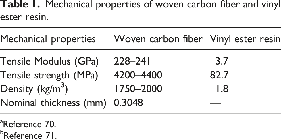
aReference 70.
bReference 71.
Woven fabric was chosen because, compared to unidirectional fibers, its fiber architecture offers better resistance to crack propagation. 73 Vinyl ester resin was chosen because it is commonly used in marine applications and offers excellent UV and corrosion resistance.74,75 When compared to polyester resins, vinyl ester demonstrates significantly reduced water absorption, which enhances its long-term durability under marine and Arctic conditions. 76 Although epoxy resins offer superior mechanical properties, their brittleness at sub-zero temperatures compromises impact resistance and increases the likelihood of cracking under stress. 77 Aramid pulp was selected because it has a hierarchical microfiber structure that provides through thickness reinforcement and creates a fiber-bridging effect, where the microfibers span across delaminated regions, physically linking adjacent layers and resisting the propagation of cracks. By absorbing and redistributing stress, this effect dissipates impact energy and significantly reduces delamination growth, thereby enhancing the laminate’s structural integrity. Alternatives such as Z-pinning, graphene nanoplatelets, and ZnO nanowires were also considered. However, these options were not selected due to their higher cost, challenges in achieving uniform dispersion, and the requirement for specialized equipment, which could com- plicate scalability in manufacturing processes. Carbon fibers were selected due to their high strength and modulus. 78
Design and manufacturing of pristine CFRP and Aramid pulp-reinforced CFRP composites
Two sets of CFRP laminates were manufactured: pristine laminates (without interlaminar reinforcement) and Aramid pulp-reinforced laminates (with Aramid pulp interlaminar reinforcement). This section will first outline the preparation process for the unreinforced resin, then describe the steps for the reinforced matrix, and finally detail the laminate manufacturing process.
Preparation of the unreinforced matrix
A vinyl ester resin was mixed with MEKP hardener in a weight ratio of 100:1.25, as per the manufacturer FibreGlast’s guidelines. The mixture was then placed in a desiccator to remove any trapped air bubbles.
Preparation of the Aramid pulp reinforced matrix
Aramid pulp is supplied by the manufacturer as conglomerated pellets, also known as clumps or closed pellets, where the microfibers are densely packed together, as shown in Figure 1(a). To break up the clumps or closed pellets, a Krupps flat-blade commercial-grade coffee grinder operating at 20,000 rpm was used. The Aramid pulp was placed into the grinder, ensuring the volume did not exceed half the blender’s capacity to prevent compaction as the fibers dispersed. The grinder was run in 20-s intervals, with pauses to reposition any fibers that stuck to the lid due to static. This cycle was repeated three times, effectively dispersing the Aramid pulp and resulting in loose, voluminous fibers without the rounded edges caused by clumping as seen in Figure 1(b). Once the Aramid pulp was adequately dispersed, it was incorporated into the vinyl resin/MEKP mixture, which had been pre-mixed for 5 min as described in subsubsection “Preparation of the unreinforced matrix.” The resin-to-Aramid pulp ratio was maintained at 15:1 by volume, following the manufacturer FibreGlast’s guidelines. A blender was selected over other common methods for opening Aramid pulp, such as immersing the clumps in acetone and then blending. The proposed method can be easily integrated into industrial settings without modifying existing composite manufacturing processes. By eliminating the need for acetone drying, the pulp can be processed immediately upon arrival using a commercially available blender, producing open Aramid pulp ready for use. (a) Agglomerated (closed) Aramid pulp and (b) post-processed (open) Aramid pulp.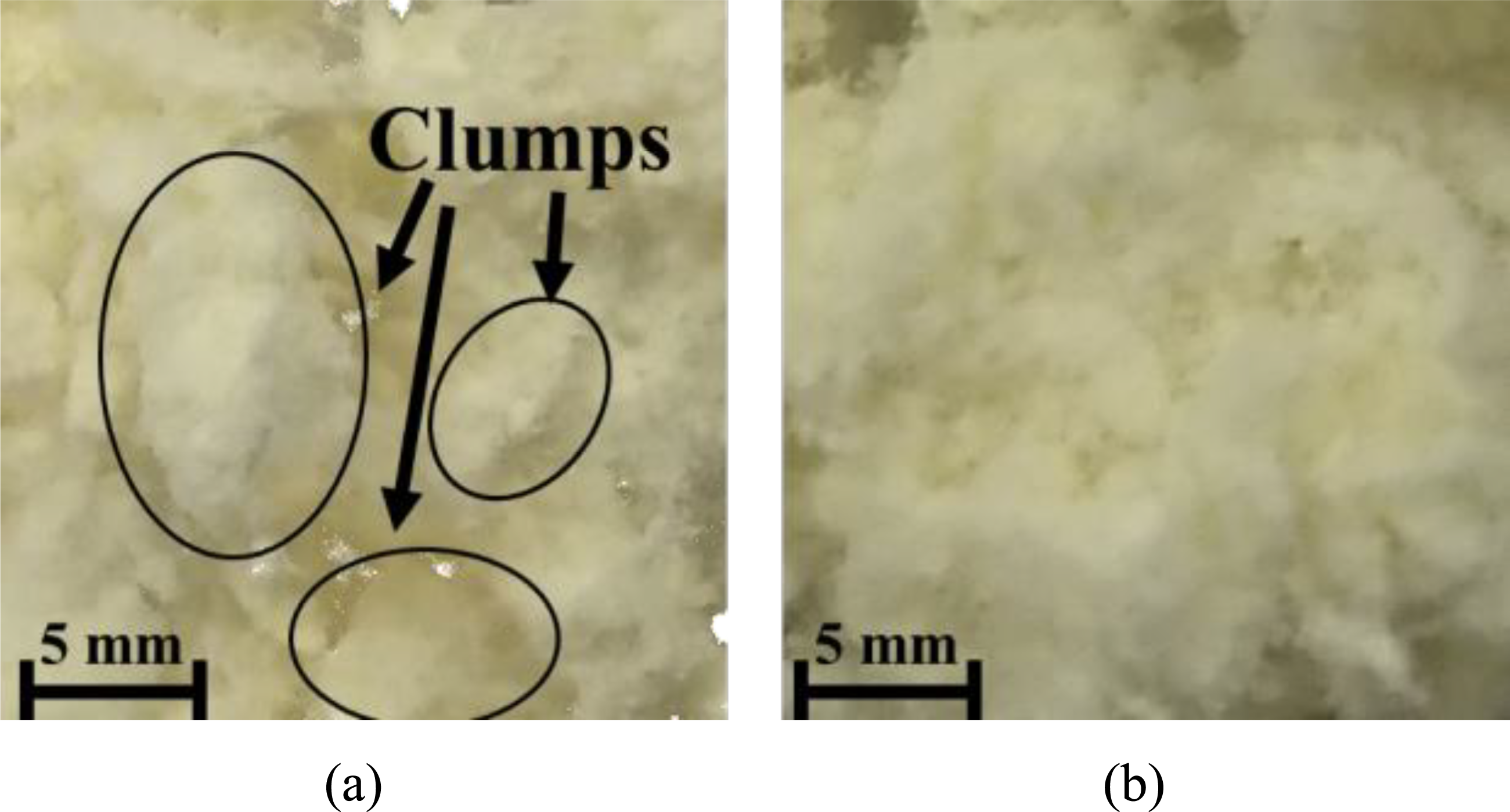
Samples manufacturing
The pristine CFRP composites and the Aramid pulp-reinforced interlaminar CFRP composites were both manufactured using the hand lay-up method. The main difference between them is the inclusion of Aramid pulp reinforcement in the reinforced samples. Figure 2 shows the manufacturing process for the reinforced CFRPs. Both the pristine and reinforced CFRPs followed the same process, including the cutting of samples. Manufacturing of Aramid pulp-reinforced CFRP specimens.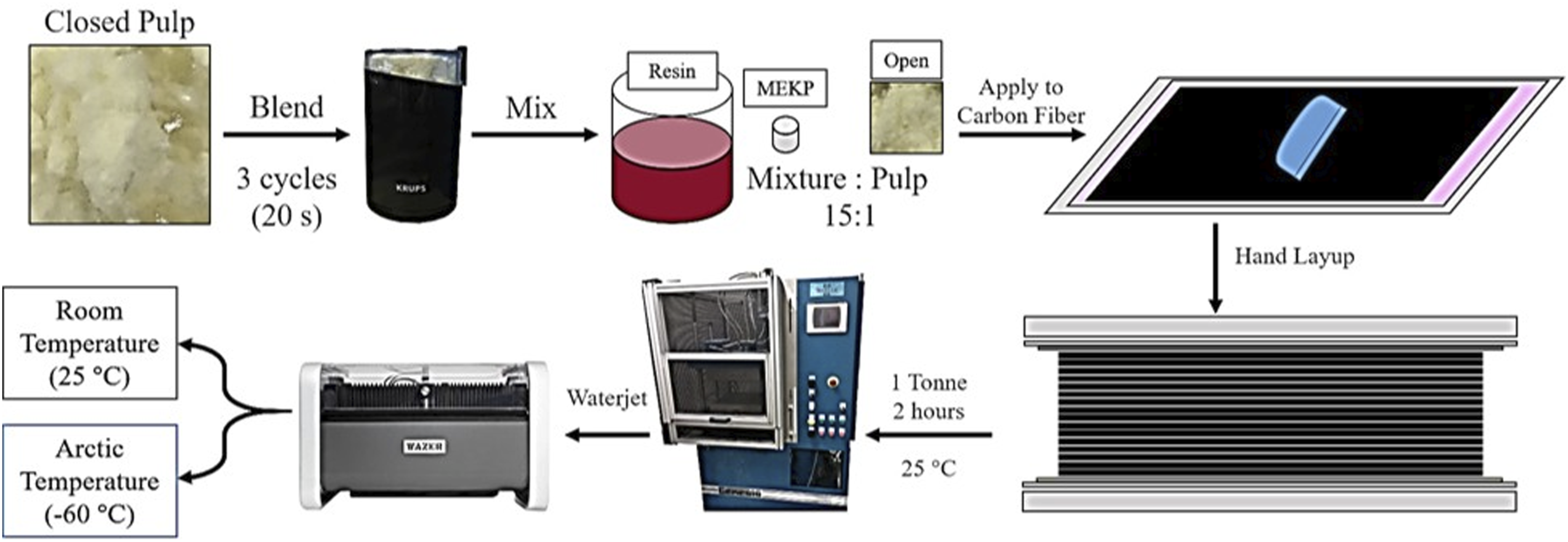
Laminates were made with 16 layers of woven carbon fabric, each cut to 350 mm × 350 mm. Two aluminum molds, each 381 mm × 381 mm, were wrapped with Stretchlon® 800 Bagging film. A Teflon sheet, also 381 mm × 381 mm, was placed on one mold to facilitate laminate removal after curing. The first woven carbon layer was laid down, and resin was applied and spread with a silicone squeegee. This process was repeated 16 times for the pristine samples (with unreinforced resin) and the reinforced samples (with Aramid pulp-reinforced resin). Once the lay-up was complete, the Teflon sheet and second aluminum mold were placed on top of the laminate. The laminate was then placed in a Wabash Genesis hydraulic press, applying a uniaxial pressure of 2 MPa at RT for 2 h. After the curing process, the laminate was removed from the press and left to rest for 24 h to ensure full curing, as recommended by the manufacturer FibreGlast. A total of 12 laminates were produced (6 pristine CFRPs and 6 Aramid pulp-reinforced CFRPs). After the 24-h resting period, the laminates were cut into specimens measuring 150 mm × 100 mm using an in-house Wazer desktop waterjet cutter. This ensured smooth edges and reduced the risk of delamination. These dimensions were based on the ASTM D7136M-20 “Standard Test Method for Measuring the Damage Resistance of a Fiber-Reinforced Polymer Matrix Composite to Drop- Weight Impact Event.” 79 After cutting, specimens were set aside for another 24 h to completely dry. The specimens were then dried for another 24 h and placed in individual plastic bags to prevent contamination before conditioning to their respective test temperatures. The thickness of the pristine and reinforced samples was 4.2 ± 0.2 mm and 4.2 ± 0.3 mm, respectively. A total of 72 specimens were obtained (36 pristine CFRPs and 36 Aramid pulp-reinforced CFRPs), allowing for the testing of 4 specimens from each group to provide representative data for each impact energy/temperature combination.
Environmental conditioning
The samples were subjected to impact testing immediately after conditioning. For RT testing (25°C), the samples were simply placed in a closed container at 25°C, as this matched the ambient temperature of the lab, so no additional conditioning was necessary. Those tested at AT (−60°C) were stored in a Thermo Fisher Scientific TSU refrigerator set to −60°C for 48 h prior to testing. Previous studies have shown that FRP composites can achieve a uniform temperature within 20 min. 80
Impact testing
A total of 72 specimens were cut using a water jet for impact testing, consisting of 36 pristine CFRPs and 36 Aramid pulp- reinforced CFRPs. Four specimens were tested for each low- velocity impact (LVI) energy level (5, 10, 15, and 20 J) under two environmental conditions: 25°C and −60°C. LVI tests were conducted using an Instron CEAST 9340 drop tower impact machine equipped with an anti-rebound device. The specimens were positioned over a steel frame with a circular opening of 76 mm in diameter, as shown in Figure 3. A steel hemispherical striker, 12.5 mm in diameter and weighing 3.1 kg, was used for all impact events. Impact test setup using instron CEAST 9340 impact test machine.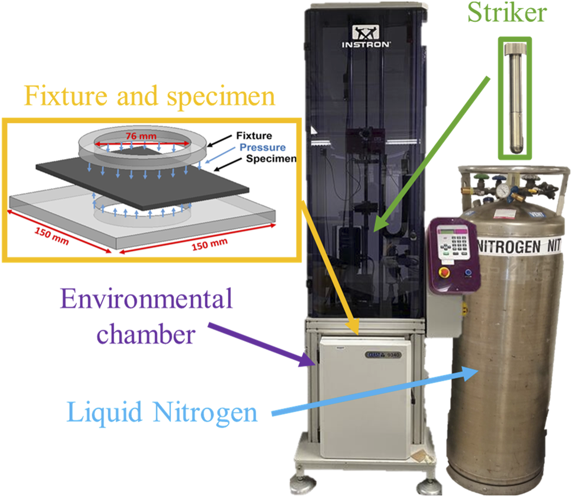
The impact energies were calculated using the Kinetic Energy (KE) equation (eq (1)):
The selected impact energies of 5, 10, 15, and 20 J corresponded to low impact velocities of 1.82 m/s, m/s, 3.16 m/s, and 3.65 m/s, respectively. The selected energy levels were chosen to induce barely visible impact damage (BVID) on the laminate’s surface while ensuring sufficient internal damage to analyze progressive damage mechanisms. This range captures the transition from initial matrix cracking and minor delamination at lower energies to more significant damage at higher energies. Additionally, these levels were set to ensure non-penetrative impacts, allowing the study to focus on damage resistance and tolerance without introducing confounding variables associated with complete material failure. The Instron impact machine determined the striker’s velocity by adjusting the initial height of the striker relative to its internal photocell, based on the potential energy (PE) equation (eq (2)):
Impact response data was recorded using the DAS 8000 Junior data acquisition system, capturing time (ms), contact force (N), velocity (m/s), energy (J), and displacement (mm) during the impact event at a sampling rate of 800 kHz. The barely visible impact damage (BVID) on both the impacted and back faces of the laminates was assessed using an AmScope optical microscope at 180× magnification, allowing for the identification of failure mechanisms. Arctic temperature tests followed the same setup as the previously described impact tests, with the addition of an environmental chamber. The chamber was preconditioned to −60°C using liquid nitrogen (LN2) for 20 min prior to each impact test. Previous studies have demonstrated that conditioning the chamber for at least 20 min ensures thermal equilibrium in the Arctic temperature environment. 81
Results and discussion
The low-velocity impact (LVI) responses of the laminates were evaluated by analyzing contact force (N), displacement (mm), energy (J), and time (ms) for impact energies of 5, 10, 15, and 20 J at two different temperatures: 25°C and −60°C. These parameters were selected to comprehensively assess the impact behavior of the laminates, capturing their ability to resist deformation and dissipate energy under different conditions. Additionally, a post-impact visual inspection was conducted using an optical microscope to assess the barely visible impact damage (BVID) on both the impacted surface and the back face of the samples.
Force-time histories
Figure 4 presents the representative force-time graphs for both pristine (unreinforced) and Aramid pulp-reinforced specimens, subjected to impact energies of 5 J 4(a), 10 J 4(b), 15 J 4(c), and 20 J 4(d), tested at both room temperature (RT) and Arctic temperature (AT). Representative force-time graphs for pristine and Aramid pulp-reinforced CFRP samples impacted at RT and AT: (a) 5 J, (b) 10 J, (c) 15 J, and (d) 20 J.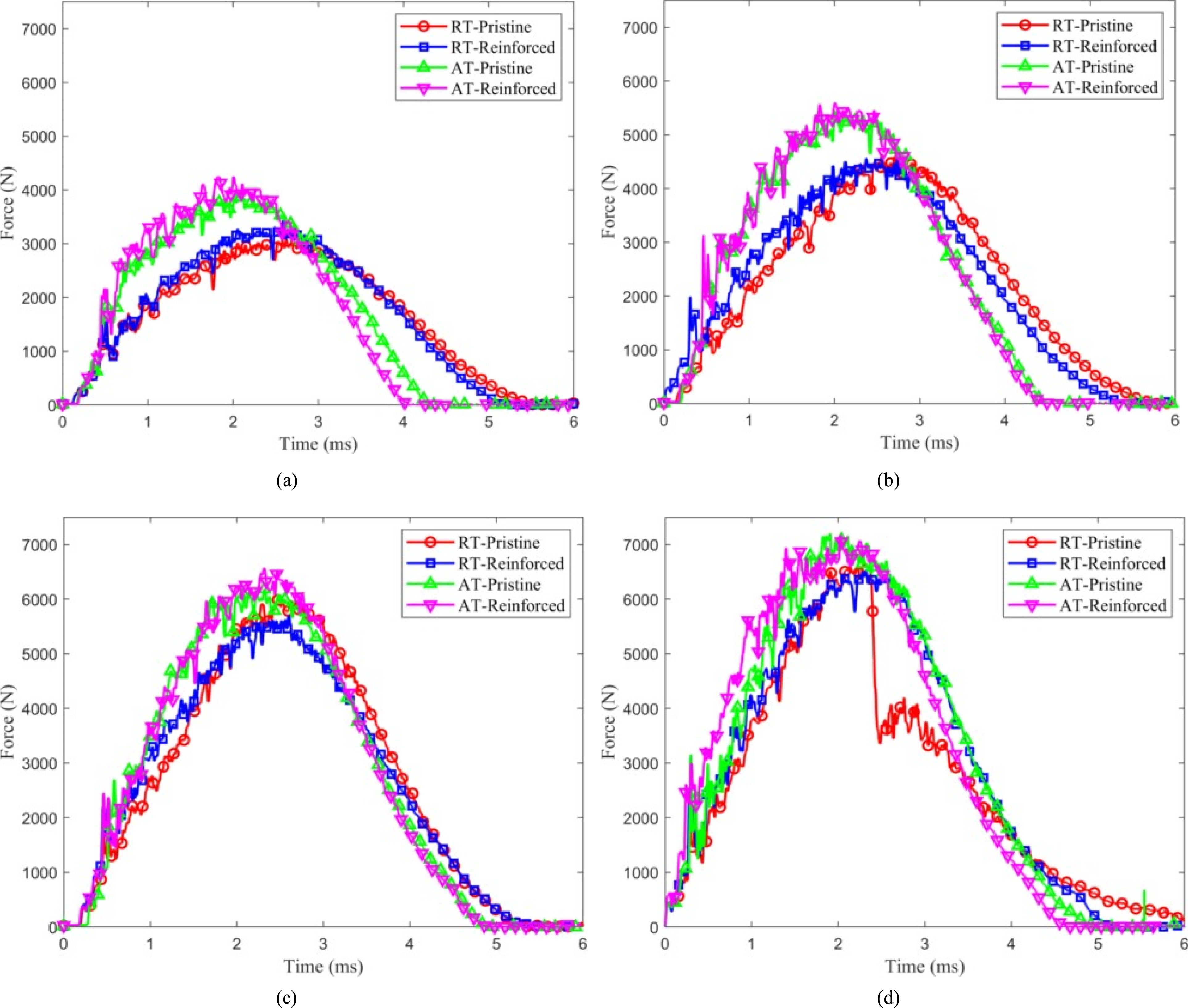
Average peak force (N) and standard deviation for pristine and Aramid pulp-reinforced CFRP samples subjected to impact energies of 5, 10, 15, and 20 J, tested at RT and AT.
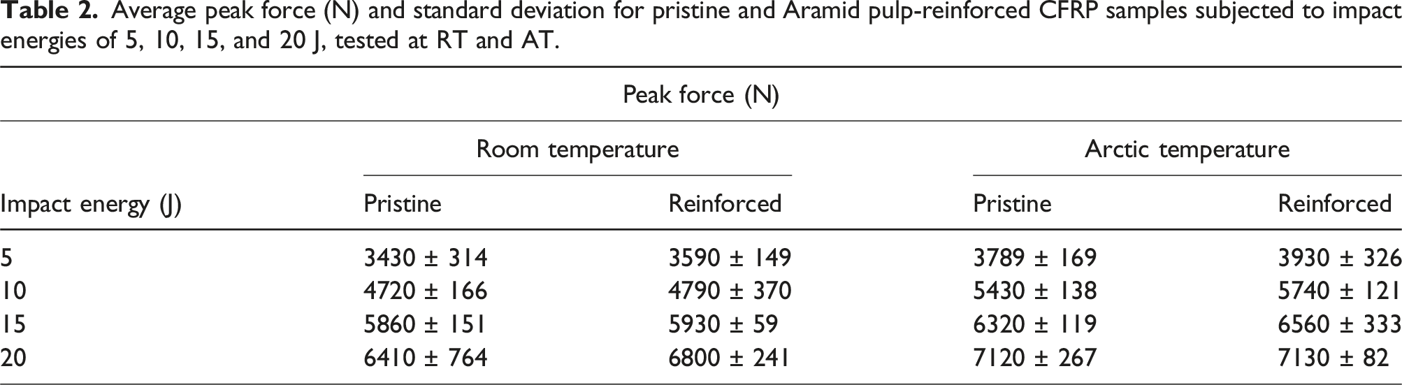
To further illustrate the effects of temperature, impact energy, and reinforcement, Figure 5(a) summarizes the peak force as a function of impact energy and testing temperature. As the temperature decreases from 25°C to −60°C, the difference in the coefficient of thermal expansion (CTE) between the fiber and matrix generates thermal stresses, resulting in compressive forces at the fiber- matrix interface, which increases the impact strength of CFRP composites.82,83 This, along with the strengthening of intermolecular bonding forces within the matrix and the reduced mobility of polymer chains in the resin at lower temperatures, leads to greater rigidity and brittleness in the CFRP laminates.84,85 Additionally, reinforced samples exhibited higher peak forces than their pristine counterparts at both RT and AT. Aramid pulp reinforcement has a hierarchical structure made up of both microfibers and nanofibers, which are uniformly and randomly dispersed between the carbon fiber layers when blended with resin. During the manufacturing process, the laminate is compressed between two aluminum molds, which forces the Aramid pulp fibers into the gaps between the woven layers, causing them to intertwine with the carbon fiber bundles. During a low-velocity impact (LVI) event, the Aramid pulp microfibers are pulled out, split, or broken, creating a fiber- bridging effect that helps reduce delamination growth. For the 5 J (Figure 4(a)) and 10 J (Figure 4(b)) impacts, samples impacted at AT, whether pristine or reinforced with Aramid pulp, exhibited shorter impact durations compared to those tested at RT. This is due to the increased rigidity of CFRP laminates at AT, which leads to faster stress transfer and quicker energy dissipation.86,87 In the 15 J (Figure 4(c)) and 20 J (Figure 4(d)) impacts, the differences in impact duration between RT and AT were minimal, likely due to damage saturation, a state reached during higher-energy impacts. In this state, the accumulation of prior damage, such as matrix cracking and fiber breakage, constrains the initiation and propagation of additional damage mechanisms. As a result, the laminate’s capacity to further absorb impact energy diminishes, indicating that the material has reached its critical damage thresholds. Generally, a longer impact duration indicates more severe internal fiber damage.
88
Average impact parameters as a function of impact energy and testing temperature: (a) peak force, (b) bending stiffness, maximum displacement, and (d) degree of damage.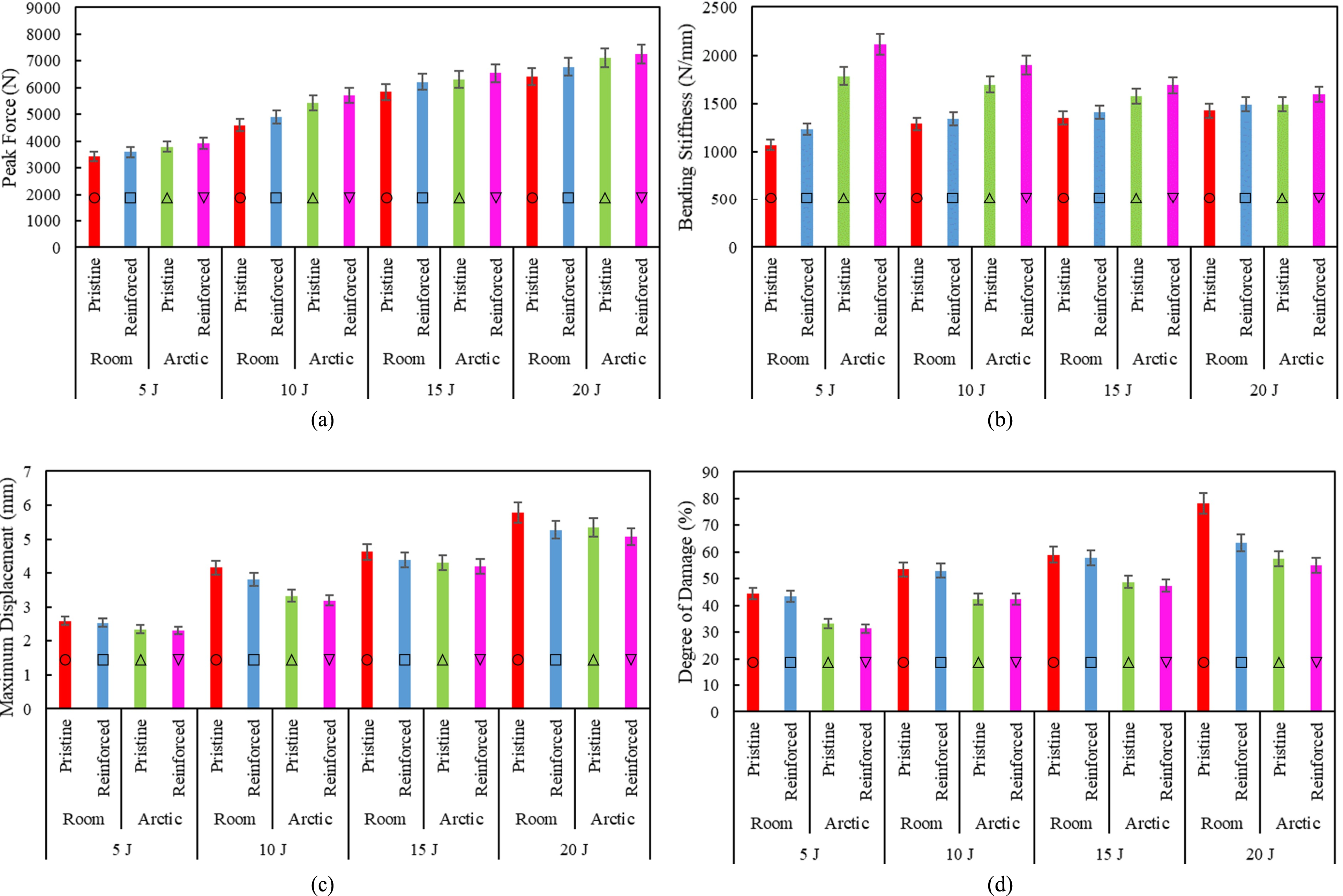
In all cases, except for the RT-pristine sample impacted at 20 J, the force decreased after reaching the peak, as the impactor began to rebound, eventually dropping to zero when the impactor detached from the laminate. However, in the RT-pristine sample impacted at 20 J (Figure 4(d)), a sudden drop in load occurred immediately after reaching the peak force, followed by oscillations. These oscillations meant a reduction in stiffness caused by unstable damage progression and are common indicators of significant failure mechanisms, including extensive fiber fractures, large delaminations, and deep punctures. 89 Eventually, the force decreased to zero, and the striker detached from the laminate. A detailed explanation of the damage mechanisms involved during impact is provided in subsection “Damage mechanisms.”
Force-displacement histories
Figure 6 presents the representative force-displacement graphs for both pristine (unreinforced) and Aramid pulp- reinforced specimens, subjected to impact energies of 5 J 6(a), 10 J 6(b), 15 J 6(c), and 20 J 6(d), tested at both room temperature (RT) and Arctic temperature (AT). The area under the force-displacement curve represents the energy absorbed by the sample, as explained in more detail in the subsection “Energy-Time Histories.” In all the graphs, the AT-Reinforced samples exhibited the smallest enclosed area, while the RT-Pristine samples showed the largest. This indicates that the RT-Pristine samples absorbed more energy, and therefore experienced the most damage among all the tests. There was not penetration in any of the laminates. For this reason, all force-displacement graphs are seen as closed type curve. In the force-displacement graphs, the oscillations in the rising section of the force indicate damage within the samples.
89
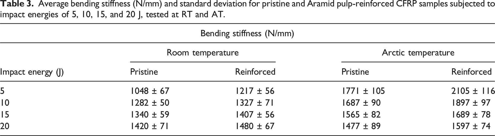
The slope of this rising section represents the bending stiffness. Bending stiffness is a critical parameter that reflects a laminate’s resistance to deformation under bending loads. It indicates the material’s ability to withstand bending forces without significant deflection, providing a measure of its structural rigidity. The average bending stiffness, along with their standard deviations, for pristine and Aramid pulp-reinforced CFRP samples at room temperature (RT) and Arctic temperature (AT) are summarized in Table 3. To further illustrate the effects of temperature, impact energy, and reinforcement, Figure 5(b) summarizes the bending stiffness as a function of both impact energy and testing temperature. Samples tested at AT, whether pristine or reinforced, experienced higher bending stiffnesses compared to those tested at RT. As previously discussed in the “Force-time histories” subsection, the increased stiffness is attributed to compressive forces at the fiber- matrix interface, caused by the mismatch in the CTE between the fiber and matrix, enhancing the laminates’ impact strength. Additionally, the matrix experiences strengthened intermolecular bonding at lower temperatures and reduced polymer chain mobility, leading to greater rigidity and brittleness in the CFRP laminates. Additionally, reinforced samples exhibited higher bending stiffness than their pristine counterparts at both RT and AT. As previously discussed in the “Force-time histories” subsection, Aramid pulp strengthens CFRP composites through its hierarchical structure of microfibers and nanofibers, which intertwine with the layers of carbon fiber. During an LVI event, the Aramid pulp microfibers undergo pull-out, splitting, or breaking, creating a fiber-bridging effect that dissipates energy and reduces delamination growth. For samples impacted at AT, bending stiffness followed a decreasing trend with increasing impact energy. This is because, at low temperatures, the matrix becomes stiffer but more brittle, and the reduction in bending stiffness is attributed to the increased damage under these conditions.
90
In contrast, the RT samples exhibited an increasing trend in bending stiffness as energy impact increased, likely due to the rate-dependency commonly observed in many polymers.
91
A detailed explanation of the damage mechanisms during impact is provided in subsection “Damage mechanisms.” Representative force-displacement graphs for pristine and Aramid pulp-reinforced CFRP samples impacted at RT and AT: (a) 5 J, (b) 10 J, (c) 15 J, and (d) 20 J. Average bending stiffness (N/mm) and standard deviation for pristine and Aramid pulp-reinforced CFRP samples subjected to impact energies of 5, 10, 15, and 20 J, tested at RT and AT.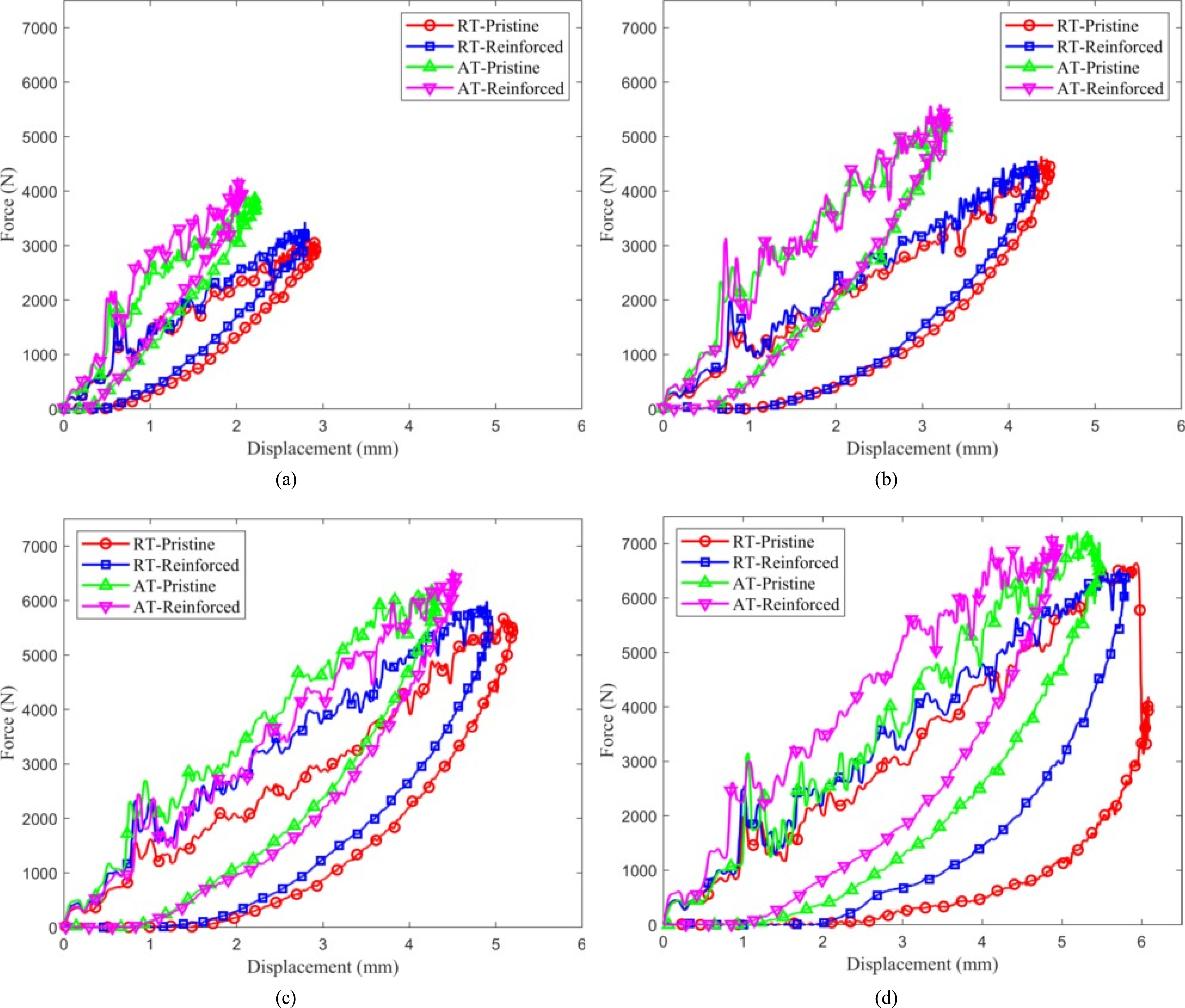
In all cases, except for the RT- pristine sample impacted at 20 J, the striker began to rebound after reaching peak force and maximum displacement, causing the force to decrease and eventually drop to zero as the striker detached from the laminate.
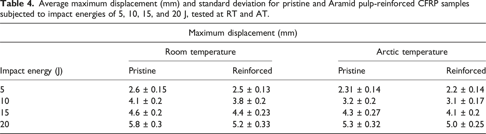
Average maximum displacement (mm) and standard deviation for pristine and Aramid pulp-reinforced CFRP samples subjected to impact energies of 5, 10, 15, and 20 J, tested at RT and AT.
Energy-time histories
Figure 7 shows a typical energy-time graph during an LVI event. As the striker makes contact with the laminate, the energy increases rapidly, showing a linear rise at the start of the graph. Typical energy-time graph during an impact event.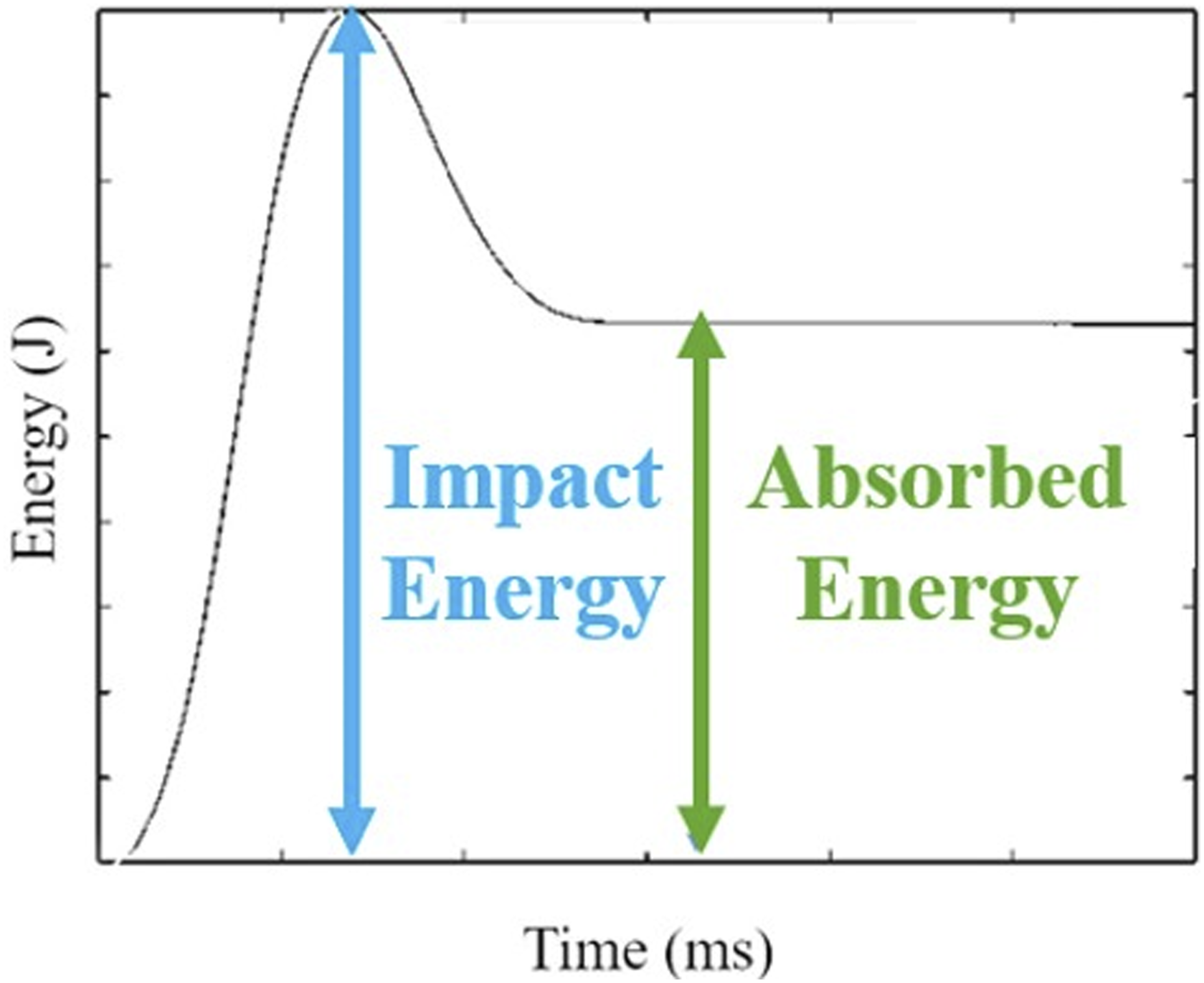
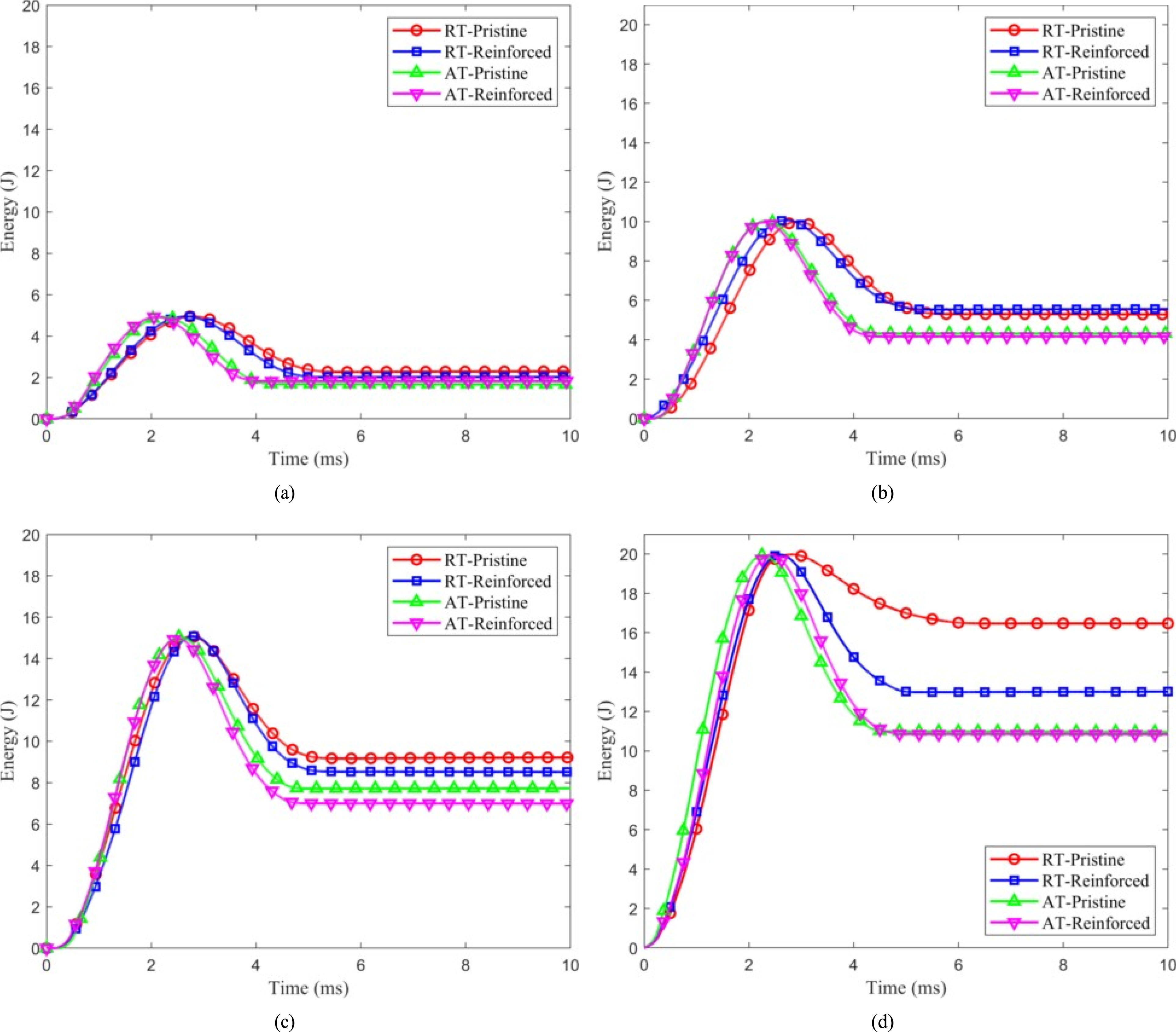
During this phase, the kinetic energy of the striker is partially converted into the specimen’s elastic potential energy, while the rest is dissipated through internal failures like matrix cracking, debonding and/or fiber fracture, and minor delaminations.92,93 The energy then reaches a peak, corresponding to the applied impact energy (5, 10, 15 or 20 J). Afterward, the curve slightly decreases as the impactor begins to rebound and detaches from the laminate. During this phase, some energy is returned as the laminate elastically recovers. In cases of severe damage (e.g., large delaminations or fiber breakage), the energy curve forms a plateau, indicating less energy recovery.
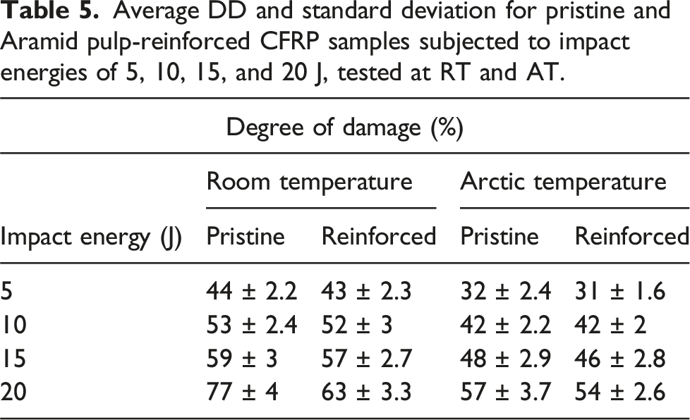
Figure 8 presents the representative energy-time graphs for both pristine (unreinforced) and Aramid pulp-reinforced specimens, subjected to impact energies of 5 J 8(a), 10 J 8(b), 15 J 8(c), and 20 J 8(d), tested at both room temperature (RT) and Arctic temperature (AT). Regardless of impact energy or testing temperature, all graphs (Figure 8) showed a plateau region that represents the absorbed energy during impact. To assess and quantify the damage caused by an LVI event, the degree of damage (DD) was calculated using the following eq (3): Representative energy-time graphs for pristine and Aramid pulp-reinforced CFRP samples impacted at RT and AT: (a) 5 J, (b) 10 J, (c) 15 J, and (d) 20 J.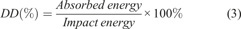
Average DD and standard deviation for pristine and Aramid pulp-reinforced CFRP samples subjected to impact energies of 5, 10, 15, and 20 J, tested at RT and AT.
Damage mechanisms
A visual inspection of the impacted laminates revealed no penetration in any of the samples, aligning with the relatively low impact energy levels used in this study. This observation is further reinforced by the closed force-displacement curves (Figure 6) recorded at all tested impact energies. Since all samples impacted at 5, 10, and 15 J exhibited similar failure mechanisms, the focus here is on the BVID of specimens impacted at 5 J and 20 J. Figure 9 shows the representative front (impacted) and back faces of both reinforced and pristine laminates subjected to 5 J at RT and AT. For the pristine sample impacted at room temperature (RT-Pristine), front-face damage was observed at the impact site in the form of matrix cracking. The cracks propagated along the fiber direction, and due to the woven structure of the laminate, a cross-pattern formed, as shown in Figure 9. Representative front (impacted) and back faces of reinforced and pristine laminates subjected to 5 J impact at room temperature (RT) and Arctic temperature (AT).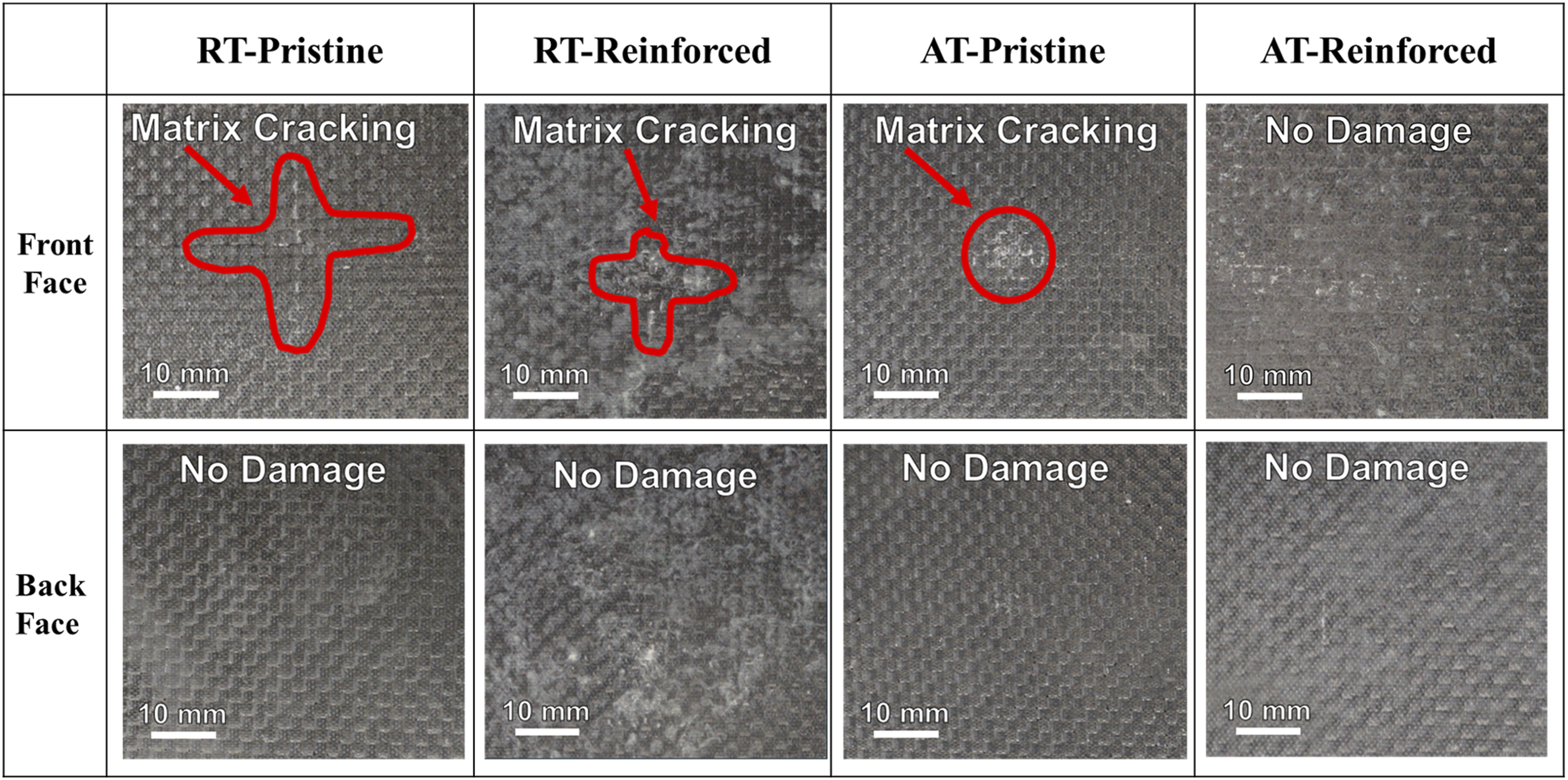
The reinforcement mechanism of aramid fibers plays a crucial role in enhancing the impact resistance of CFRP laminates. The hierarchical microfiber structure of aramid fibers bridges interlaminar regions, preventing delamination growth and increasing the energy required for crack propagation. This fiber-bridging effect suppresses delamination by physically linking adjacent layers, while simultaneously improving the toughness of the interlaminar region. Additionally, within the intralaminar region, aramid fibers deflect cracks and absorb impact energy through fiber pull-out and splitting mechanisms, thereby mitigating matrix cracking and reducing overall damage severity. These reinforcement mechanisms were evident in the experimental results. The RT-Reinforced samples exhibited front-face damage with a smaller cross-pattern matrix crack compared to the RT-Pristine sample. This reduction in damage severity is attributed to the fiber-bridging effect of aramid fibers, which prevented crack propagation and localized stress concentrations. In both RT-Reinforced and RT-Pristine samples, no damage was observed on the back face of the laminate, highlighting the role of reinforcement in confining damage to the front face. For samples tested at AT, the results further demonstrate the effectiveness of aramid fiber reinforcement. The AT-Pristine front face exhibited circular indents with no back face damage, likely due to the increased stiffness and rigidity of the laminate at low temperatures. In contrast, the AT-Reinforced samples showed no visible damage on either the front or back faces, suggesting that the combined effects of low-temperature-induced rigidity and Aramid pulp reinforcement provided superior damage resistance. The hierarchical structure of aramid fibers not only enhanced the matrix toughness but also minimized delamination growth by absorbing and dissipating impact energy. Figure 10 shows the representative front (impacted) and back faces of both reinforced and pristine laminates subjected to a 20 J impact at RT and AT. The RT-Pristine sample exhibited a larger cross-pattern matrix crack on the front face, while the back face showed both fiber fracture and matrix cracking. Notably, RT-pristine samples impacted at 20 J were the only ones to exhibit a load drop in their force-time and force-displacement graphs (Figures 4 and 6). This sudden drop in load corresponds to fiber fracture, as seen in the images, indicating significant degradation of the laminate’s mechanical properties. Higher absorbed energy results in larger damage areas, as discussed in the energy-time histories section. Additionally, the RT- Pristine sample experienced the longest impact duration, further corroborating that a longer impact contact duration signifies more serious internal damage, particularly fiber fracture. In contrast, both the RT-Reinforced and AT- Pristine samples exhibited smaller cross-pattern cracks on the front face compared to the RT-Pristine sample, with matrix cracking observed on the back face only. For the AT- Reinforced sample, both the front and back faces showed matrix cracking, but the damage on the front face was notably smaller than that of the RT-Pristine, RT-Reinforced, and AT-Pristine samples. This observation highlights the combined benefits of Arctic temperature-induced stiffness and aramid fiber reinforcement in mitigating damage and maintaining structural integrity under impact conditions. Representative front (impacted) and back faces of reinforced and pristine laminates subjected to 20 J impact at room temperature (RT) and Arctic temperature (AT).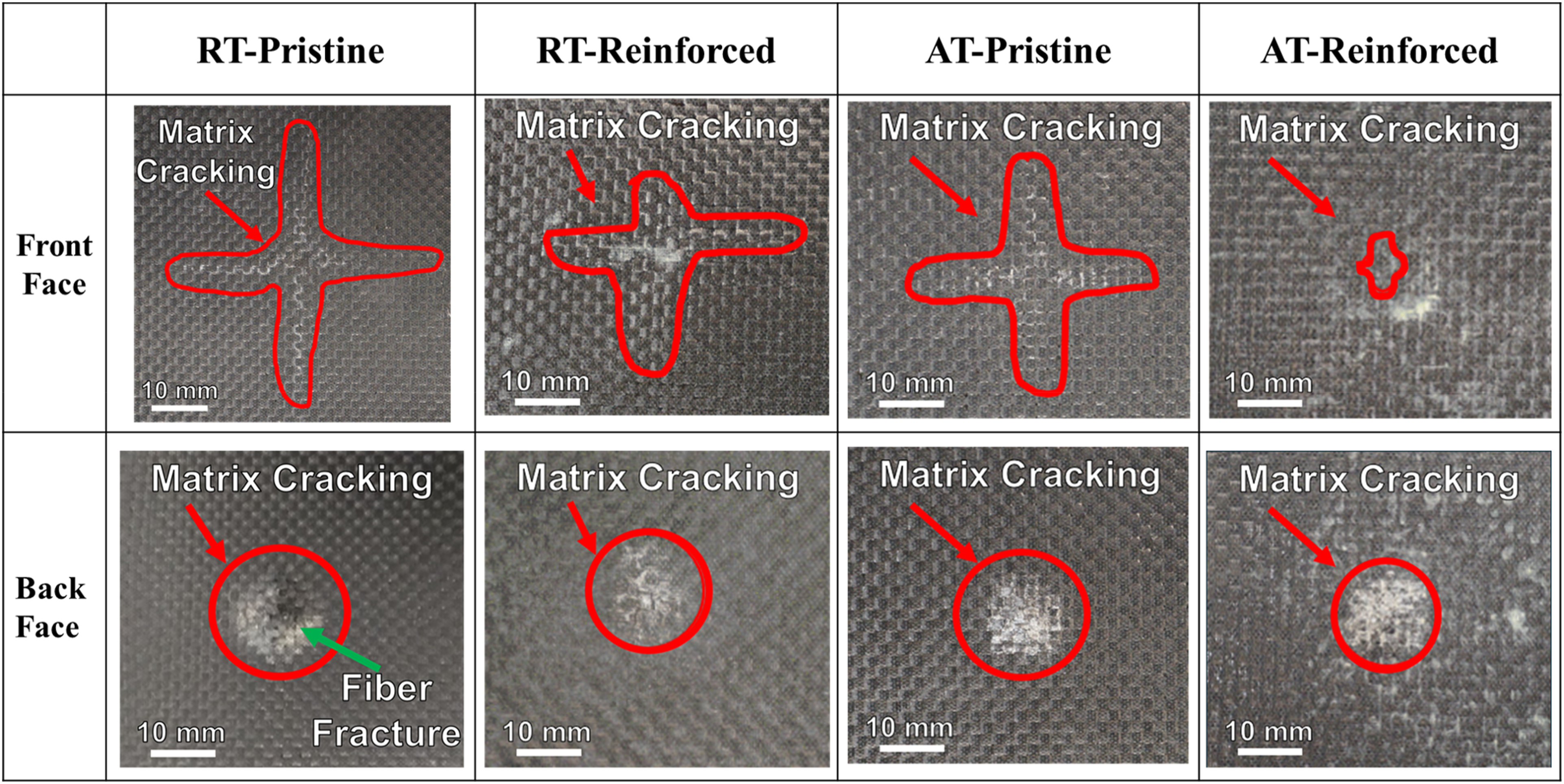
Limitations and future work
While the study demonstrates the effectiveness of Aramid pulp reinforcement in enhancing the impact resistance of woven CFRP laminates under Arctic conditions, several limitations should be acknowledged. First, the findings are specific to the woven carbon fiber and vinyl-ester resin system used in this study. The transferability of these results to other composite architectures, such as unidirectional or hybrid laminates, may vary due to differences in fiber-matrix interactions and damage mechanisms. Future studies should investigate the applicability of Aramid pulp reinforcement in diverse composite systems to expand its utility. Second, this study was conducted on small-scale specimens fabricated in a controlled laboratory environment. While the results provide valuable insights, scalability to larger structures or components used in industrial applications may present challenges. Factors such as uniform dispersion of Aramid pulp in larger laminates, potential processing complexities, and cost implications need to be thoroughly evaluated for practical implementation. The cost of raw Aramid pulp is generally higher than traditional reinforcements, such as short fibers or interleaving films. However, this increase can be offset by its scalability and ease of integration into existing manufacturing processes. Unlike methods such as Z-pinning or nanomaterial-based reinforcements, Aramid pulp does not require specialized equipment or significant process modifications, potentially reducing operational costs. Additionally, the improved damage resistance and durability of Aramid pulp-reinforced composites could result in lower maintenance and replacement costs, offering long- term economic benefits in applications where reliability is critical. Future research should include a detailed cost- benefit analysis to quantify these trade-offs, taking into account material costs, processing expenses, and lifecycle savings. Lastly, the impact conditions simulated in this study represent a specific range of low-velocity impacts relevant to Arctic environments. Real-world scenarios may involveadditional factors, such as varying impact angles, dynamic loading conditions, or combined environmental stressors (e.g., UV radiation, saltwater exposure). Future work should aim to address these variables to ensure the robustness and reliability of the findings across broader application scenarios.
Conclusion
This study thoroughly analyzed the effects of Arctic temperature (AT), Aramid-pulp reinforcement, and varying impact energies on the impact response of CFRP composites subjected to low-velocity impact. To gain deeper insights, LVI tests were conducted at both AT and room temperature (RT) on pristine and reinforced samples. Based on the experiments, the following results were obtained: (i) The increased rigidity and stiffness of the laminates at AT resulted in higher bending stiffness and peak forces, while also leading to lower DD and displacement compared to the RT samples. This increased stiffness is attributed to the reduced mobility of polymer chains and the mismatch in CTE, which generates compressive forces at the fiber-matrix interface, thereby enhancing the impact strength of CFRP composites. (ii) The increased stiffness and damage resistance of laminates with Aramid pulp interlaminar reinforcement led to lower DD and displacements, along with higher peak forces and bending stiffness, compared to their pristine counterparts across all impact energies and temperature conditions. This improvement is attributed to the hierarchical microfiber and nanofiber structures, which reinforce the matrix by forming inter-ply fiber bridges, effectively reducing delamination and crack propagation. (iii) The main failure mechanism observed on both the impacted and back faces of the laminates was matrix cracking, present in all pristine and Aramid pulp- reinforced samples. The only exception was the RT-pristine sample impacted at 20 J, which also exhibited fiber fracture on the back face. Overall, the AT samples showed less damage than the RT samples, and the Aramid pulp-reinforced specimens experienced less damage compared to their pristine counterparts. Consequently, the Aramid pulp-reinforced samples tested at AT demonstrated the most rigid and stiff response among all tested samples.
Aramid pulp shows strong potential as an interlaminar reinforcement for AT applications. Both AT conditions and Aramid pulp reinforcement enhanced the impact damage tolerance of plain weave carbon fiber/vinyl-ester laminates during LVI scenarios, primarily due to the increased rigidity and stiffness of the matrix. Notably, the addition of Aramid pulp did not significantly increase the laminate thickness, making it a viable option for large-scale composite production.
In addition to advancing the understanding of reinforced CFRP laminates, this research demonstrates the potential for practical applications in industries such as Arctic shipping, renewable energy, and aerospace. The scalability of Aramid pulp reinforcement and its compatibility with existing manufacturing processes suggest that these materials could be industrially adopted within a short to medium timeframe—potentially within 5 years. Achieving this will require further large-scale testing, cost-benefit analyses, and validation under real-world conditions. By addressing current limitations, this technology has the potential to redefine material design for extreme environments, offering a transformative solution for critical applications.
Footnotes
Acknowledgements
The authors express their sincere gratitude to the University of Texas at El Paso for their invaluable support via the University Research Initiative (URI) and startup grants, which were instrumental in the research presented in this article.
Author contributions
Conceptualization, A.C.; methodology, A.C.; validation, A.C. and Z.N.; formal analysis, Z.N.; investigation, Z.N.; resources, A.C.; data curation, Z.N.; writing—original draft preparation, A.C. and Z.N.; writing—review and editing, A.C.; visualization, A.C.; supervision, A.C.; project administration, A.C.; funding acquisition, A.C. All authors have read and agreed to the published version of the manuscript.
Declaration of conflicting interests
The author(s) declared no potential conflicts of interest with respect to the research, authorship, and/or publication of this article.
Funding
The author(s) disclosed receipt of the following financial support for the research, authorship, and/or publication of this article: This research was funded by The University of Texas at El Paso, a startup grant.
Data Availability Statement
Data is contained within the article.