
Abstract
Laminates are produced by stacking prefabricated plies composed of fiber products. Within the aerospace industry, a ply thickness of 125 μm is commonly regarded as the standard. Ply thicknesses of less than 100 μm are generally considered as thin plies. Due to their ability to provide superior mechanical properties relative to conventional laminates thin-ply (TP) laminates are gaining interest in several high-tech industries. Although the research on TP laminates increased over the past few years, a comprehensive evaluation of the mechanical behavior of TP laminates accounting for the ply-thickness is an ongoing challenge due to the intricacies of ply interactions, and experimental difficulties. The mechanical response of fiber reinforced polymer laminates is governed by damage progression during loading, with the thickness of individual plies playing a crucial role in influencing the initiation and evolution of local cracks and failures. Therefore, in this study, the effective mechanical properties of carbon fiber reinforced polymer composite with varied ply thicknesses have been experimentally evaluated and the accumulation of the damage events has been monitored using acoustic emission measurements, utilizing a contactless laser vibrometer. In this experimental study, the ply thickness is increased in a systematic manner (ranging from 50 μm to 200 μm). Experimental investigation has been carried out in quasi-static tension and compression. The results show that unnotched TP laminates subjected to tensile loading demonstrate enhanced effective strength, attributed to less premature failure. Conversely, as the thickness of the lamina increases, there is a reduction in the overall strength of the laminate. However, in the case of the notched specimen lowest strength has been observed at a ply-thickness of 100 μm in this study. Under compressive loading, unnotched and notched specimen tends to show similar mechanical behavior to unnotched specimens under tensile loading. The overall strength is raised with decreasing ply thickness. The findings from this study may be valuable for incorporating ply-thickness considerations into models for predicting the mechanical performance of laminates under dynamic loading.
Introduction
Composite laminates consist of multiple layers of lamina, made from matrix and reinforcement materials, bonded and stacked together in a specific manner for the required application. Due to their high strength-to-weight ratio, continuous fiber-reinforced composites have become the material of choice in many industries, such as wind energy, aerospace, and aviation. However, predicting the mechanical behavior of these materials remains challenging, primarily due to their inhomogeneous structure and complex damage mechanisms. The most distinctive failure modes are delamination, fiber failure, and inter-fiber failure. A comprehensive understanding of these failure modes, including their initiation and progression, is crucial for predicting the mechanical response of composites. In the case of a unidirectional (UD) laminate, final failure may be dominated by one of the aforementioned damage mechanisms. However, when assessing failure mechanisms in multidirectional laminates, the complexity increases due to the presence of multiple failure modes and their interactions.
In recent years, the Carbon Fiber Reinforced Polymer (CFRP) industry has witnessed significant progress, with a particular emphasis on expanding the design possibilities in manufacturing. This progress has enabled increased control over factors such as ply thickness,
1
fiber orientations,
2
management of uncertainties related to material parameters,
3
and the optimization of controlled manufacturing environments.
4
Thin-ply (TP) multi-directional laminates (ply thickness
Guillamet et al.
12
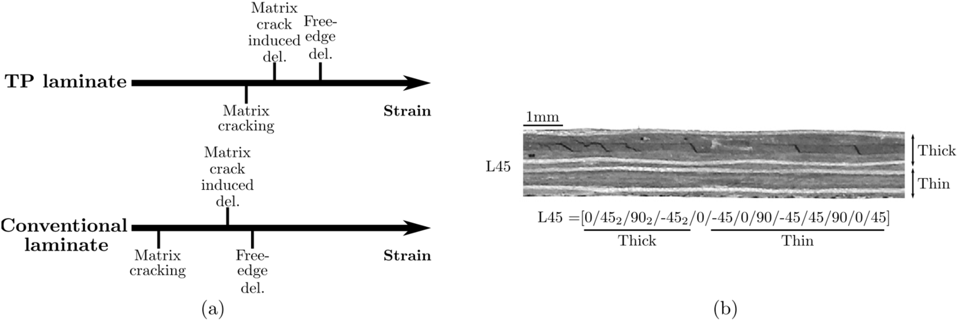
reported an experimental investigation of damage occurrence in a quasi-isotropic laminate, consisting of a combination of partially TP and partially thick-ply regions. Their study illustrates that transverse matrix cracking damage is delayed in the thin region and appears at 33% (on average) higher strain than in the thick region. The subsequent matrix crack-induced delamination is also postponed in the thin region and occurs at a significantly higher strain than in the thick region, as illustrated in Figure 1(a). Due to the decrease in ply thickness, the peak strain energy value reduces at the crack tip for matrix crack-induced delamination. Consequently, when the maximum strain energy at the tip becomes lower than the threshold value for crack extension due to a decrease in ply thickness, crack propagation is suppressed.13,14 The study by Guillamet et al.
12
further demonstrates a significant improvement in delamination resistance at the free edge in thin plies, where free-edge delamination appeared at 10% in the thick region prior to its occurrence in the thin region (see Figure 1(b)).
12
The increase in ply thickness escalates the interlaminar stresses, thereby resulting in early free-edge delamination in the thick region.
11
In another study by Huang et al.,
15
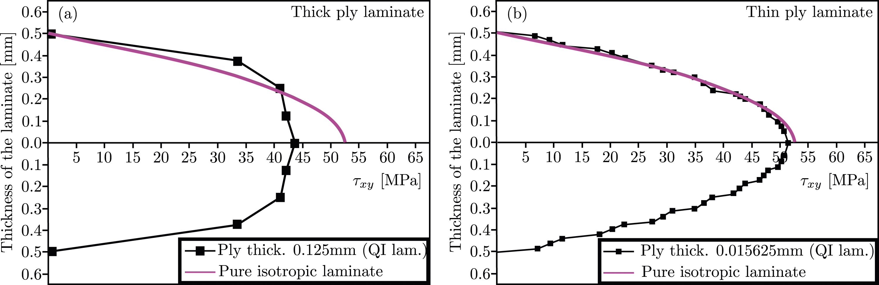
the interlaminar stress distribution for thin and thick ply laminates is evaluated in detail (Figure 2). They reported that the gradient of interlaminar shear stress between the layers, caused by irregularities in the interlaminar shear stress distribution, is higher for thick-ply laminates. This could potentially lead to premature interlaminar failures. Conversely, TP laminates tend to have a more continuous interlaminar shear stress distribution, leading to an improvement in interlaminar properties. This effect in TP laminates makes the deformation of adjacent layers more consistent and improves the ability to resist failures due to interlaminar shear stresses. Distribution of interlaminar shear stress on the cross-section of (a) thick ply and (b) thin-plies in a QI laminate layup, where the pure isotropic laminate is considered without the influence of plies.
15
Further research on TP laminates depicts that reducing the ply thickness can lead to significant improvements in terms of first-ply/first-damage criteria, as well as fatigue life and ultimate strength.
10
Additionally, numerous experimental studies illustrate the trend of the increased effective strength of the laminate as ply thickness reduces.6,10 As a result, it can be inferred that the delay in fiber fracture also occurs in TP laminates relative to conventional laminates, due to delayed transverse matrix cracking, matrix crack-induced delamination, and free-edge delamination. Moreover, in TP laminates, damage events are not only delayed, but they also occur within a short interval during loading, resulting in more spontaneous complete failure compared to the gradual final failure observed in standard laminates. The study by Ramezani et al.
17
reveals that the primary reason for the resistance of thin plies to crack propagation lies in the uniform distribution of fibers and the reduced occurrence of resin-rich and fiber-rich areas within these thin plies. Yokozeki et al.
16
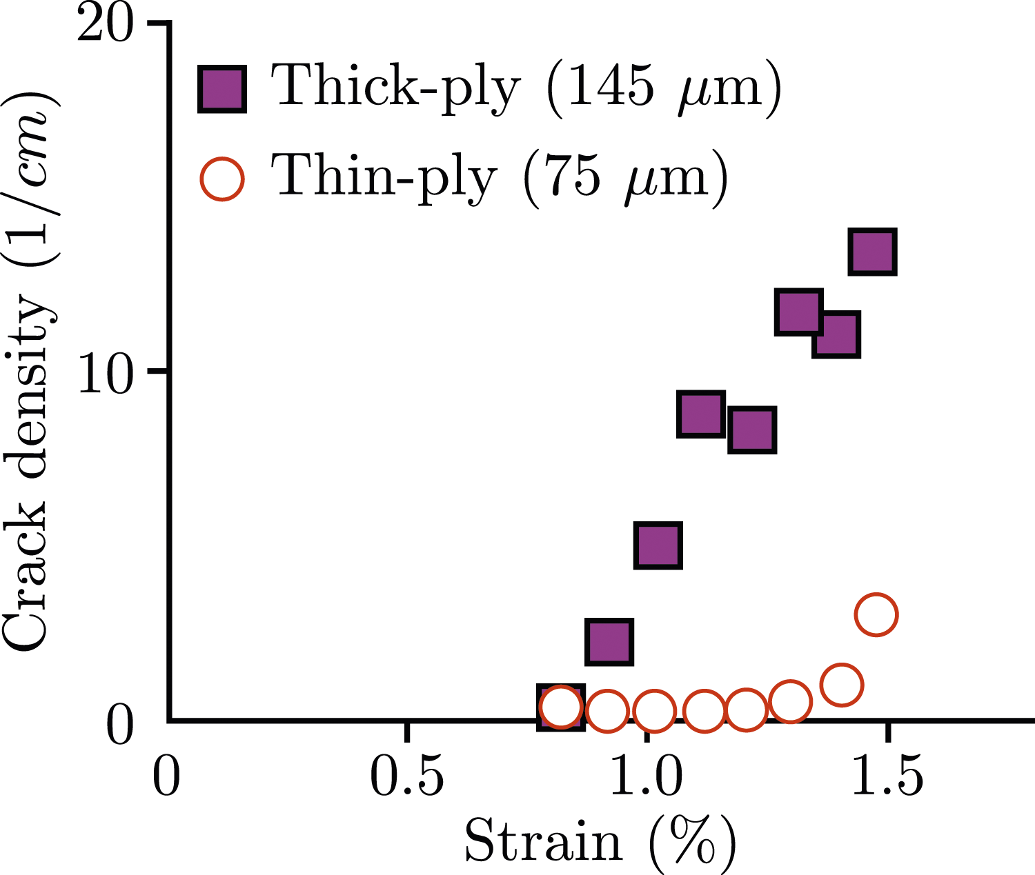
demonstrated a comparison of damage event accumulation in thin- and thick-ply laminates through acoustic emission (AE) observations, as depicted in Figure 3. They illustrate the relationship between the applied strain and the accumulated matrix crack density in 90° plies, defined as the number of observed matrix cracks per unit observation length. One of the main observations is the clear retardation of matrix crack accumulation in the TP laminates, which demonstrates the superiority of TP laminates in resisting premature crack accumulation, leading to higher damage resistance than standard laminates. From the well-documented literature, it can be noted that varying ply thickness can have a drastic effect on the structural performance of composites, allowing TP laminates to provide new perspectives for innovative structural applications.
18
While existing literature documents the superiority of TP laminates over standard laminates in terms of strength and delaying damage occurrence, the precise relationship between the premature damage events, their accumulation, and the resulting changes in mechanical behavior remains an active area of research. The accumulation of crack density due to damage events in CFRP laminate under quasi-static tensile loading
16
.
One method commonly used for monitoring damage evolution in composite materials is the AE technique. 19 AE is generated by stress waves resulting from localized damage events. Evaluating these emissions offers several advantages, including high sensitivity in detecting damage, precise localization of events, and in situ damage assessment.20,21 A key benefit of AE is its ability to assess damage that is not visually observable, particularly in fiber-reinforced polymers (FRPs), where epoxy serves as the matrix.22,23 For example, conventional optical techniques often struggle to evaluate damage events in such composites, making AE especially valuable in glass and carbon composites, as extensively documented in the literature.24–27 In recent years, this technique has successfully assessed damage in various types of composites, including glass,28,29 carbon,30,31 and aramid32,33 fiber-reinforced composites. In an initial investigation, Dogossy and Czigány 34 and Nimdum and Renard 35 effectively employed AE monitoring to characterize failure mechanisms during tensile loading. Similarly, Anuar et al. 36 utilized AE to assess failure modes in composites. Gutkin et al. 31 used the AE technique to analyze the distinct failure modes in an extensive range of test campaigns, including tension, compact tension, compression, double cantilever beam, and end-notched flexure on CFRP specimens. Saeedifar et al. 37 used the AE technique for damage characterization in bi-material double-lap adhesively bonded joints and confirmed that AE findings are consistent with observations from other standard techniques, including digital image correlation and fiber optic sensors. In another study, Ichenihi et al. 38 applied the AE technique to analyze damage in combined continuous and discontinuous thermoplastic carbon/glass hybrid composites, reporting that the AE technique can efficiently identify fiber breakages separately for glass and carbon fibers.
Fotouhi et al. 39 explored the possibility of linking AE events with the corresponding damage modes in TP UD carbon/glass hybrid laminates under tensile loading. They reported that AE can be successfully used for detecting damage initiation, as well as for subsequent tracking of its evolution. In a recent study, Huang et al. 40 used the AE technique to identify the failure modes of TP laminates containing circular holes under tensile loading, demonstrating the versatility of AE techniques at the microscale. Their results further confirmed a stronger damage suppression effect and crack propagation resistance in the TP laminates containing circular holes, using the AE technique along with finite element verification. Nevertheless, both studies did not account for ply thickness variations in detail, and the research was limited to specific composite geometry, layup, and loading conditions (tensile loading). However, these studies collectively demonstrate the versatility and effectiveness of the AE technique in monitoring damage across a wide range of composites.
Considering the aforementioned literature, the AE technique for monitoring failure occurrences in TP laminates appears to be a reliable and effective method. While it is well-established that TP laminates demonstrate superior performance compared to standard laminates, the precise relationship between premature damage occurrences and the resulting variations in mechanical behavior remains relatively unexplored. Techniques like AE could prove highly useful in this context, especially given the intricate interactions among the thin plies of multidirectional TP laminates. Furthermore, the correlation between premature damage events and their progression to final failure with changes in ply thickness (moving from thinner plies to thicker plies) still requires research attention. This aspect is crucial because it significantly influences the effective mechanical performance of the laminate. As a result, this study undertakes an investigation to identify possible premature damage accumulations in composites by employing an advanced AE monitoring technique. This investigation offers novel insight into the interplay between ply thickness and overall mechanical performance by identifying the premature damages and their accumulation until ultimate failure. Although such a study will contribute significantly to the advancement of the applicability of TP laminates, it remains unexplored in the literature. In a nutshell, the novelty of this work lies in understanding the mechanical properties of carbon-fiber epoxy TP composites with varied ply thicknesses, where localized damages before final failure are analyzed using a sophisticated AE measuring approach.
The paper is divided into four sections. The second section provides a detailed description of the materials used and outlines the experimental methodology employed in the campaign. The third section is dedicated to the evaluation of the results obtained, analyzing and discussing the findings. The summary and concluding remarks can be found in the fourth section.
Materials and methods
Material and specimen preparation
In the present investigation, Toray T800SC/epoxy UD prepreg tapes with a ply thickness of 50 μm have been used. The laminates were manufactured at the German Aerospace Research Center (DLR), Stade. The specimens used for the tests are manufactured from UD layers. An increase in the ply thickness has been achieved by laminate block scaling,
10
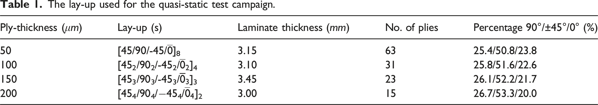
i.e., multiple layers of the same fiber orientation are considered as a single ply. Therefore, laminates of different ply thicknesses can be manufactured using one type of UD-prepreg. The stacking sequence of the laminate used in this study is [45
m
/90
m
/-45
m
/ Microsections of laminates with layer thicknesses of (a) 50 μm, (b) 100 μm, (c) 150 μm, and (d) 200 μm. At the top, the plies are stacked together to form a laminate, while at the bottom, the individual fiber bundles with resin for the respective laminates are displayed. The lay-up used for the quasi-static test campaign.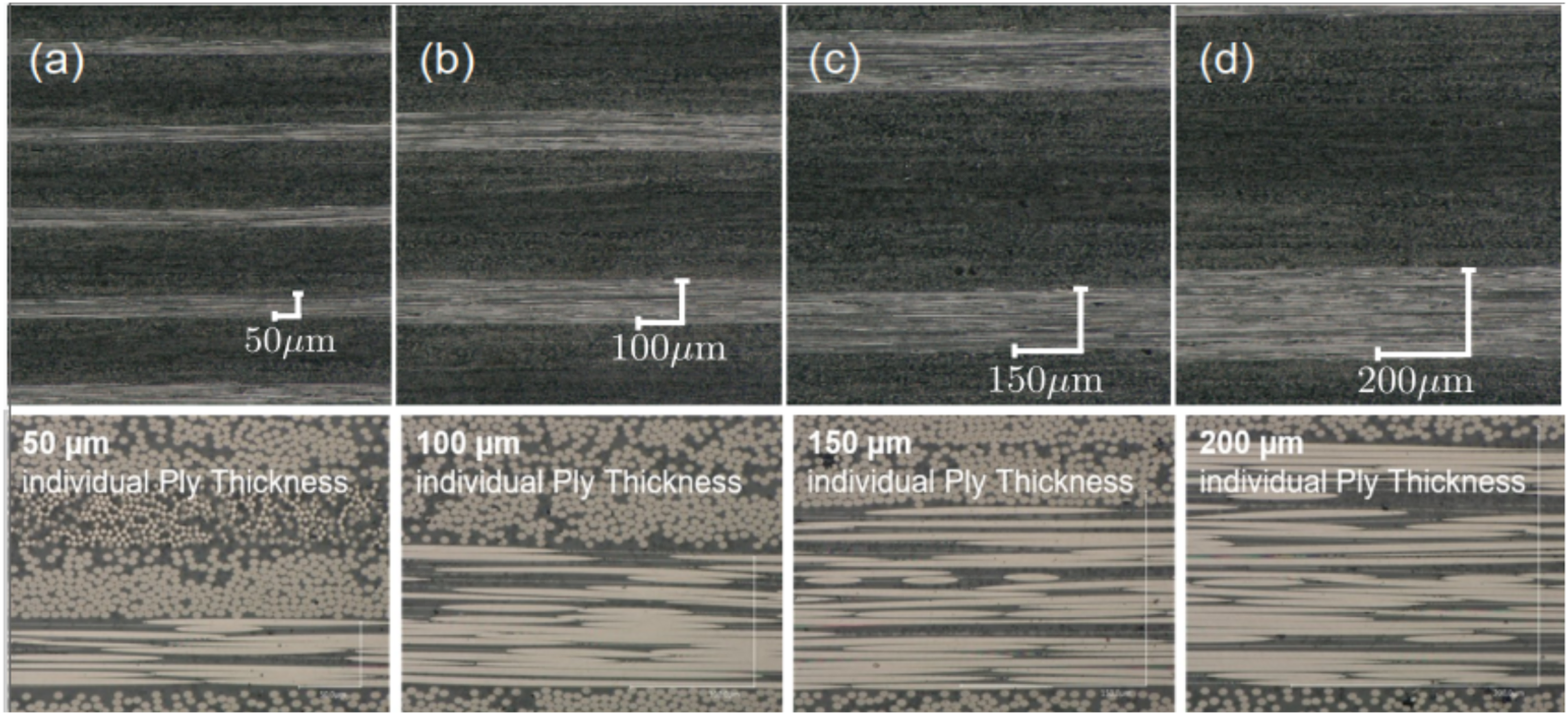
For tensile and compression tests, the specimens have been cut using a water-cooled circular saw. For the open hole (OH) tests, 6 mm diameter holes have been drilled using a drill specified for carbon fiber reinforced polymers. To minimize defects from cutting and drilling, special attention was given to the preparation process, where the sample edges were ground with 600 and 1200 grit abrasive paper after sawing to reduce edge effects. Tabs were attached to the tensile, compression, and OH specimens using 3M™ Scotch-Weld™ DP490 and featuring a 1 mm thickness of glass fiber reinforced polymer laminate to mitigate stress concentration and to prevent failure in or close to the clamping.
Experimental campaign
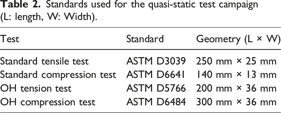
Standards used for the quasi-static test campaign (L: length, W: Width).
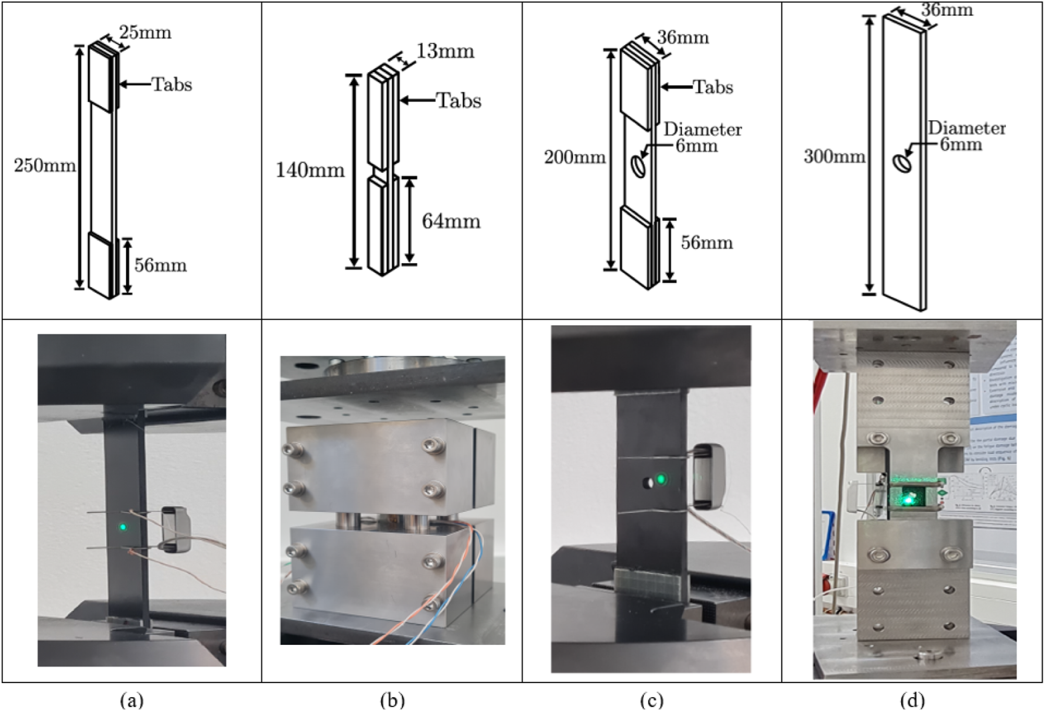
Geometric representation of test specimens and the experimental setup for (a) standard tensile, (b) standard compression, (c) OH tensile, and (d) OH compression tests.
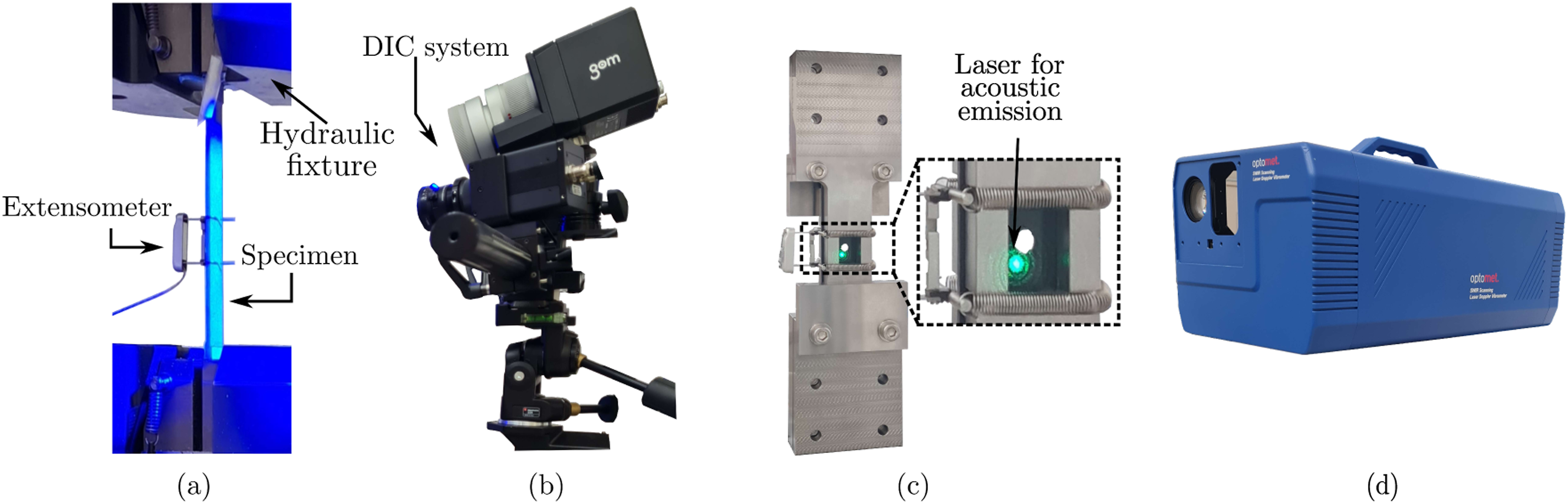
(a) Hydraulic testing machine with specimen and extensometer, (b) Digital image correlation (DIC) system, (c) OH compression testing fixture with laser pointer for acoustic emissions measurement, and (d) Optomet laser doppler vibrometer.
This state-of-the-art AE monitoring equipment provides highly reliable measurement results and can be implemented at a distance from the specimen. In contrast to surface-bonded sensors, the influence of contact quality or the weight of the sensors is not a concern. Another argument for choosing this contactless measurement technique is the planned fatigue test campaign that will follow this campaign. Therefore, this measurement technique would be especially beneficial in dynamic testing.
Results and discussion
A quasi-static test campaign was undertaken to investigate the influence of ply thickness on unnotched and notched specimens (with and without holes) subjected to both tensile and compressive loads. Detailed discussions of the results are provided in the following subsections.
Standard tensile tests
Figure 7 shows the tensile test results of the selected unnotched specimens of laminates for the lay-up shown in Table 1. A comparison of ultimate tensile strength is presented Table 3
1
. Stress-strain curves of standard tensile tests for (a) 50 μm, (b) 100 μm, (c) 150 μm, and (d) 200 μm ply-thickness laminate. Ultimate tensile strength (UTS) and percentage increase of the strength for standard tensile tests, the percentage increase in the strength is relative to the 50 μm and 200 μm laminate.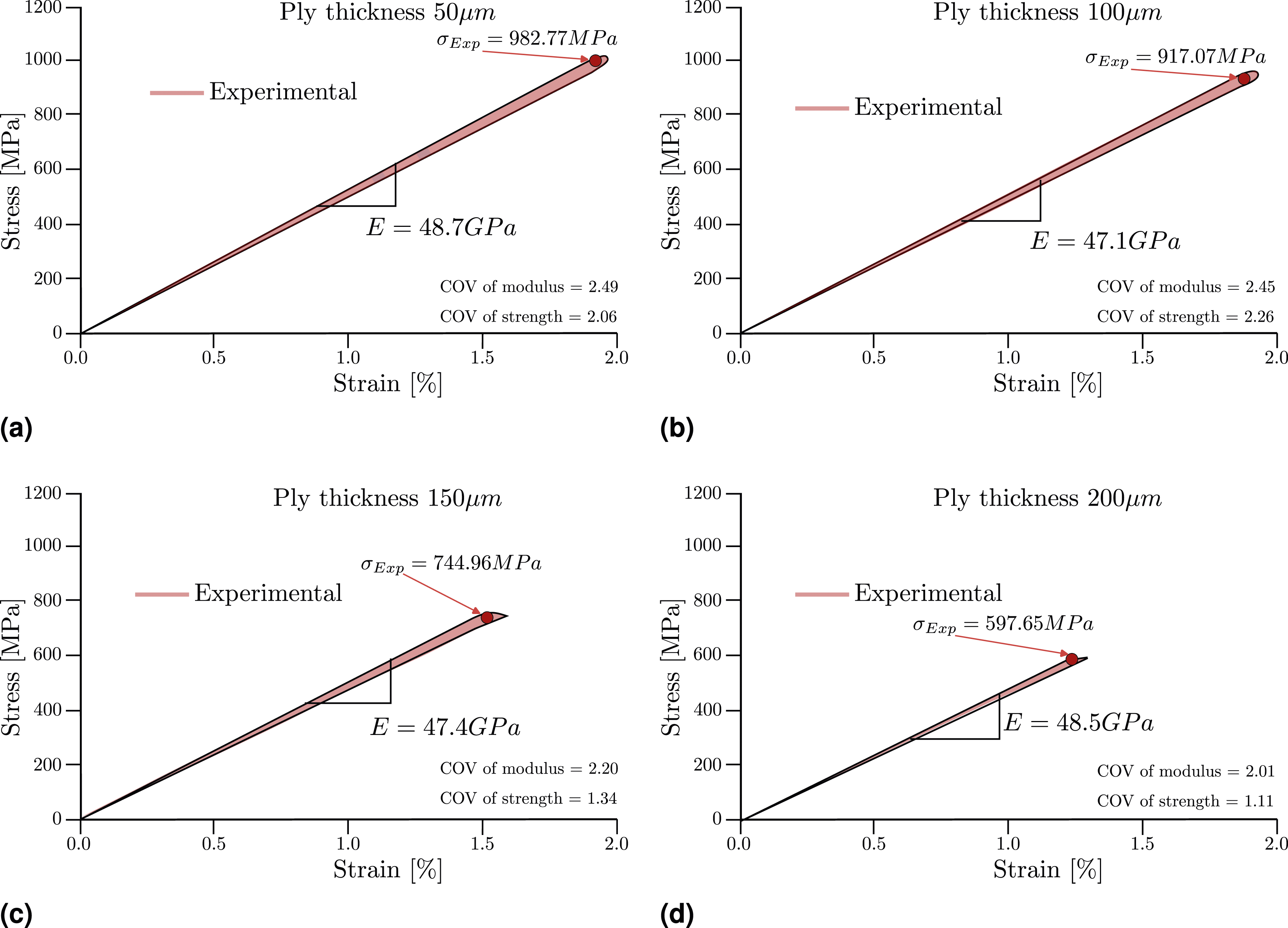
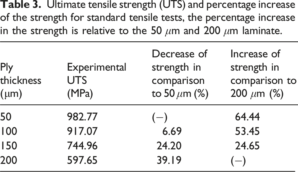
The observed trend demonstrates that with increasing ply thickness, there is a noticeable reduction in strength values, while the elastic stiffness remains relatively constant. The increase in ply thickness leads to irregularities in interlaminar shear stress distribution and inhomogeneity of the microstructure. This results in interlaminar-rich resin regions (at ply interfaces) that are more susceptible to failure, consequently leading to a reduction in overall strength. Conversely, the homogeneous interlaminar shear stress distribution with lower ply thickness is beneficial, as it leads to a continuous stress gradient and smaller differences in interlaminar stresses between adjacent plies, thereby enhancing overall strength. Similar observations are highlighted in the work of Huang et al., 15 where they discuss how the use of thinner plies allows for a larger number of ply orientations within a given laminate thickness. This results in a more uniform distribution of interlaminar shear stresses and a reduction in stress concentrations, which could otherwise lead to premature failure. It is clear from Table 3 that the laminate with 50 μm exhibits significantly higher tensile strength, which is 64.44% higher compared to the 200 μm laminate. A similar influence of ply thickness on material behavior has been reported by Kötter et al. 6 and Amacher et al. 10 for tensile tests under quasi-static loading conditions. As mentioned by Amacher et al., 10 these significant improvements can be correlated to the change in the failure pattern, where TP composites exhibit a substantial delay in their damage progression and demonstrate a quasi-brittle failure mode, instead of extensive delamination and transverse cracking.
To further explore the strength variations with changes in ply thickness, AE measurements have been performed, and the test results on respective samples with thicknesses of 50 μm, 100 μm, 150 μm, and 200 μm laminates are illustrated in Figure 8. A single plot has been presented for the AE measurement results on each specimen, containing two curves plotted against time for the complete loading process. The stress-time curve is represented by an orange dashed line, while the blue solid line depicts the vibration speed of the specimen’s surface. The released energy during each damage event is indicated by spikes in the blue curve, as measured by the AE laser vibrometer. In each measurement, at the final failure, there is a spike indicating complete damage. Prior to this point, each spike indicates premature damage, which may result from a single damage event or a combination of such damage events. Although five tests were conducted for AE measurements, due to the controlled manufacturing and testing environment, majority of the samples showed very similar AE measurements. Considering the same, the most common result has been presented here for the sake of brevity. AE results on standard tensile samples with the thickness of (a) 50 μm, (b) 100 μm, (c) 150 μm, and (d) 200 μm.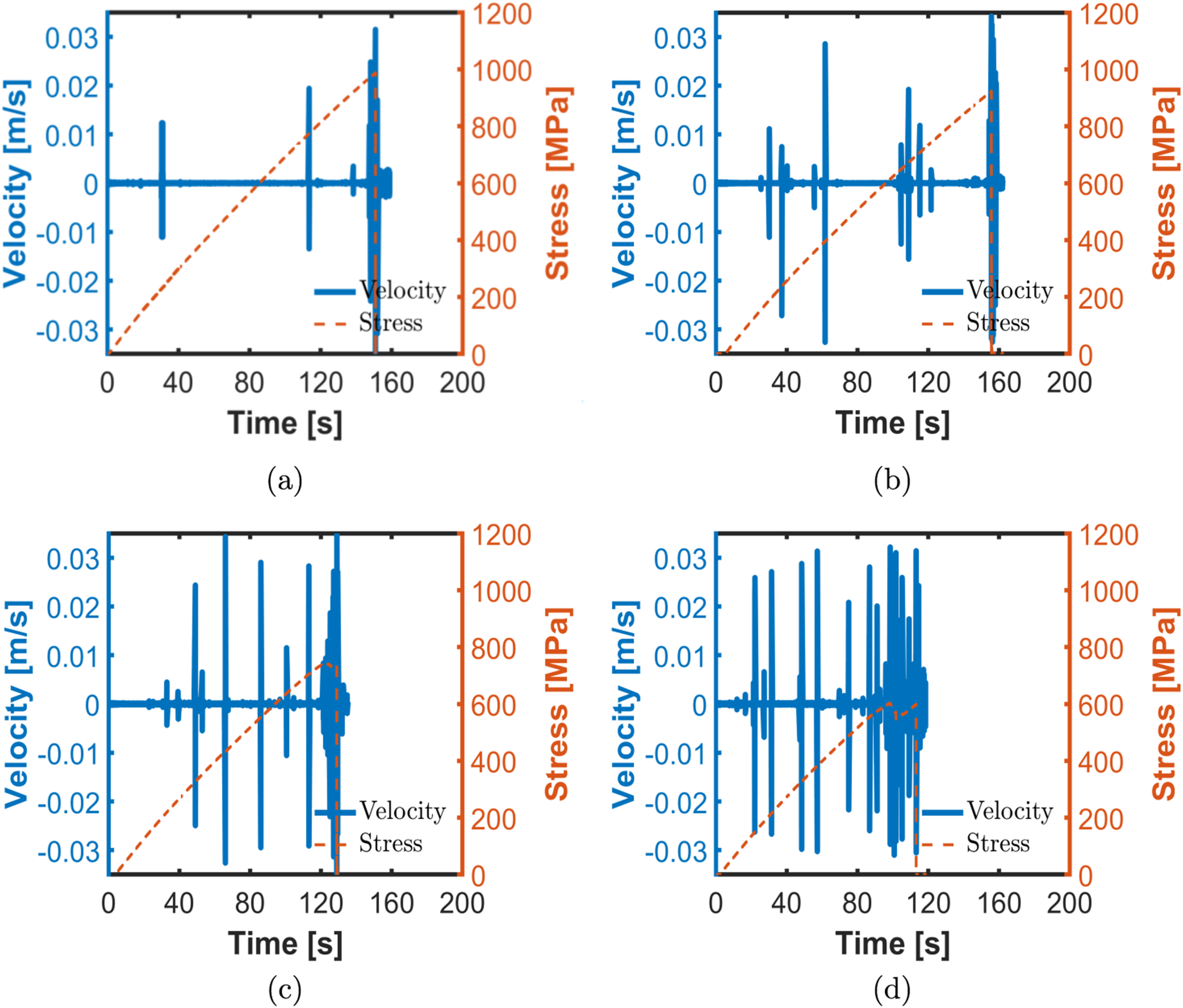
According to the results obtained from the AE analysis, an increase in the frequency of spikes in the blue curve can be observed with an increase in thickness from 50 μm to 200 μm. These fluctuations observed in the blue curves with the increase in ply thickness confirm the early stage of damage events occurring in the laminate. This further strengthens the conclusions regarding the increase in strength with a decrease in thickness. Similar discussions are also reported in the studies of Guillamet et al. 12 and Saito et al. 42
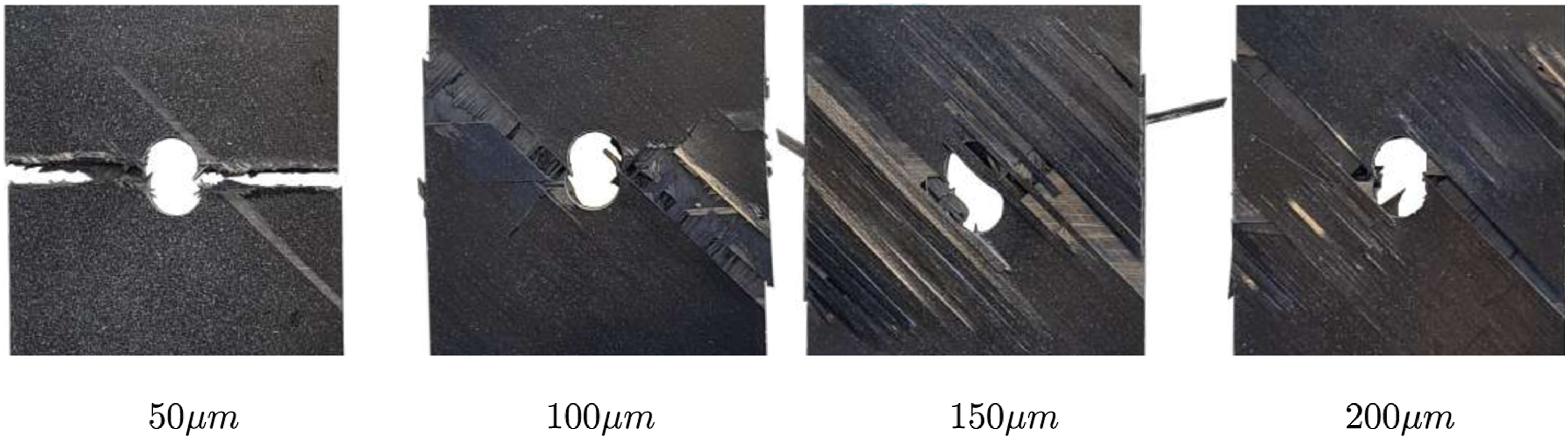
The experimental damage patterns are depicted in Figure 9. Confirming the AE measurements in Figure 8 and the failure pattern shown in Figure 9, it is observed that thinner ply laminates (50 μm) did not show signs of cracking and delamination until final failure, exhibiting no visible indications of premature damage. In contrast, as the thickness increases, the damage mechanism varies, corresponding to Figure 1, with delamination dominating in the thicker ply laminates, i.e., 150 μm and 200 μm. This may occur due to matrix cracking in the 90° ply as an initial event, followed by matrix cracking in the 45° ply, which induces delamination. However, this damage sequence is not observable in the final failure pattern shown in Figure 9. The ultimate failure may be due to splitting, delamination, and fiber failure in the 0° ply, which is consistent with the observations by Ramezani et al.
17
and Aoki et al.
43
Ultimate damage pattern from the standard tensile test on the unnotched specimen.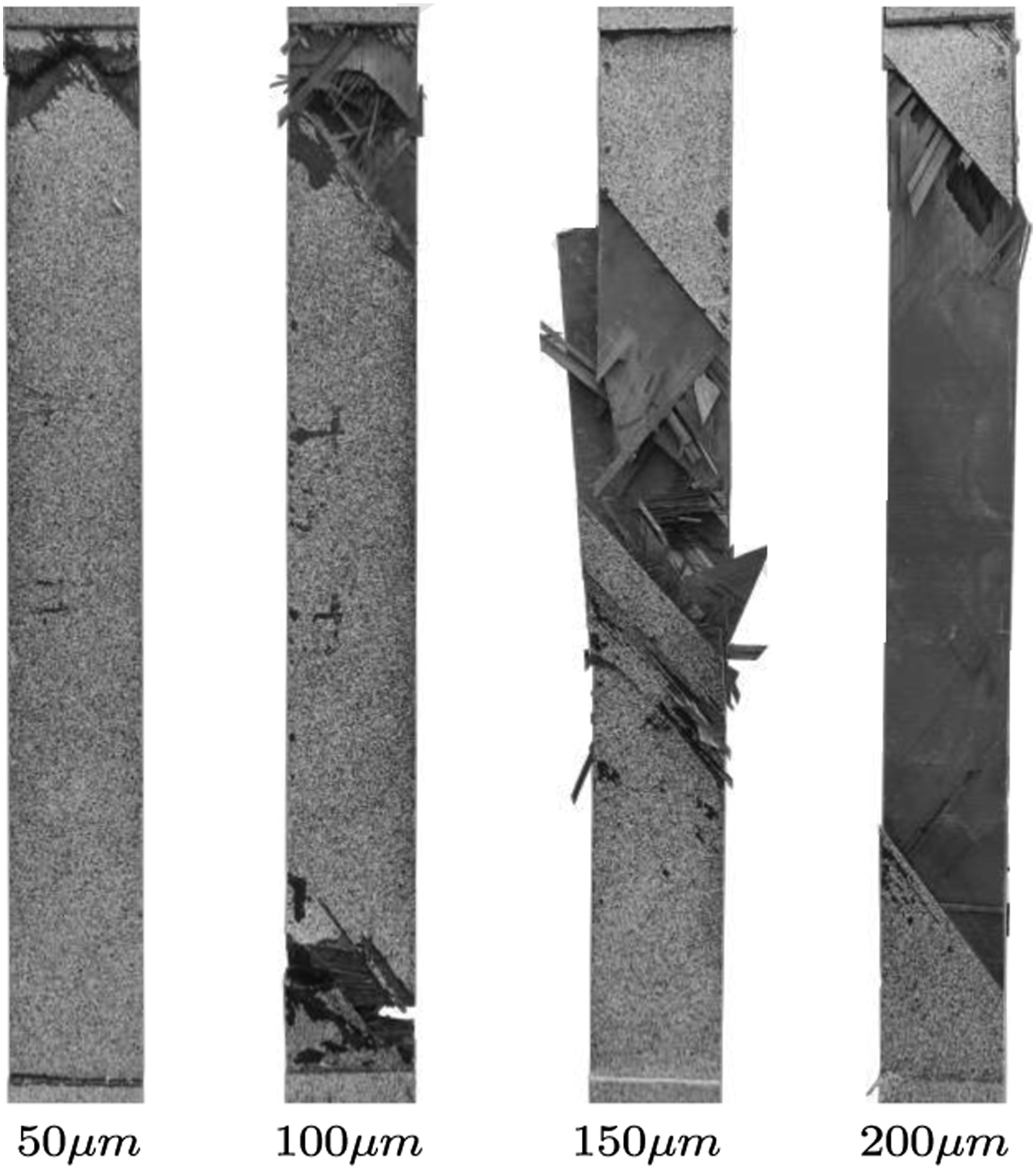
In quasi-static tensile stress tests with a 50 μm ply thickness, minimal acoustic signatures of premature damage have been observed. However, they are not significant when compared to thicker plies, as crack initiation and progression are suppressed in the TP laminate. 12 Interestingly, the strength is 64.44% higher than that of the thicker ply (specifically, the laminate with a 200 μm ply thickness), as demonstrated by experimental results in Table 3. The effective strength of a laminate is due to fibers being longitudinal to the loading direction, which may be influenced by premature damage events during loading. The predominant damage events observed in the TP laminate (i.e., 50 μm) were matrix cracking and fiber failure (see Figure 9), and the final failure involved the suppression of delamination (initiation and propagation of matrix-crack-induced delamination, see Figure 1) until ultimate failure, as depicted in Figure 9. Based on the visual impression of the results, as the ply thickness increases, a large number of acoustic events (referred to as high AE density) are observed, indicating a progressive and significant increase in damage events. This further confirms the rise in premature damage accumulation, as also shown in Refs.17,43 This may have led to delamination (as illustrated in Figure 9), thereby influencing the effective strength of the laminate.
Open-hole tensile tests
Figure 10 represents the results from the OH tensile tests of the respective laminate for the lay-up shown in Table 1. In the OH tensile tests, it was noted that the overall strength characteristics of the laminate did not follow a similar trend to the standard tensile tests without a hole (i.e., decreasing strength with an increase in thickness), even though a similar damage pattern was observed in Figure 11. Effective ultimate strength of OH tensile tests on the selected TP laminates. Damage pattern for specimen with the progressive variation of layer thicknesses for OH tensile tests.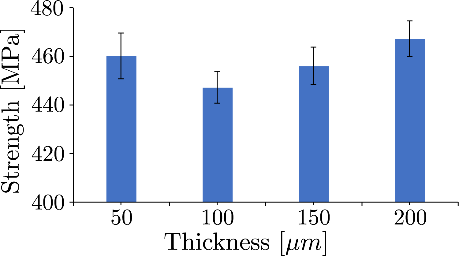
With the increase in thickness from 50 μm to 100 μm, the OH tensile strength reduces by 2.83%. This trend is similar to the observations in the standard tensile test (without a hole), confirming the finding of the superiority of TP laminates in terms of strength parameters. Nevertheless, an anomaly has been observed with a further increase in ply thickness. For instance, with an increase in thickness to 150 μm and 200 μm, a slight increase in OH tensile strength is noted. This phenomenon may be attributed to stress redistribution mechanisms, wherein stress redistributes away from the holes toward undamaged regions. As a result, the stress peak near the hole is reduced. The redistribution of stresses, caused by the quasi-plastic behavior due to material non-linearities and local damage at the hole edges, results in a mechanism that alleviates stress concentrations induced by the hole.44,45 This redistribution results in an enhanced effective OH tensile strength with an increase in thickness. This effect plays a pivotal role in mitigating damage or stress concentrations away from the hole, consequently increasing the load-carrying capacity of the laminate and contributing to reduced premature damages. Similar findings have been documented in the existing literature by Wisnom and Hallett
46
and Fukada
47
This redistribution can be further visualized in the digital image correlation (DIC) test results illustrated in Figure 12. DIC test results for laminate for the outer 45° layer with thicknesses of (a) 50 μm, (b) 100 μm, (c) 150 μm, and (d) 200 μm.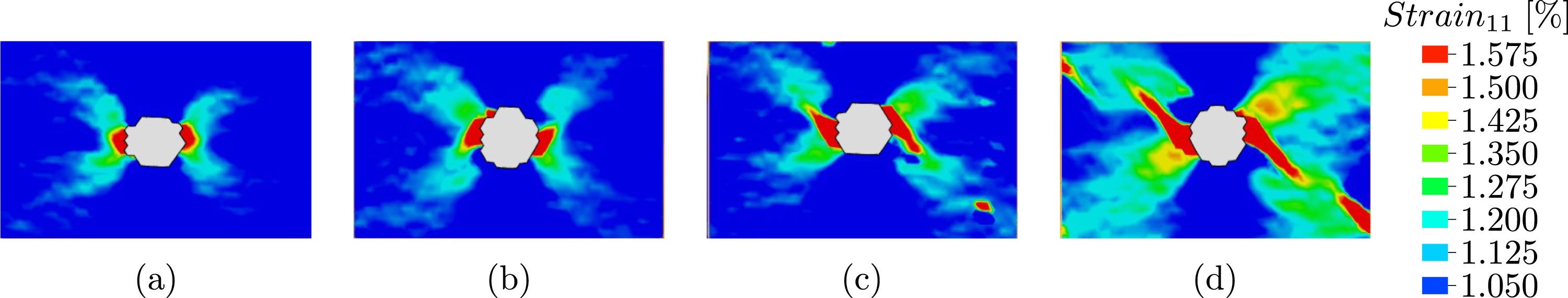
These DIC images were taken just before the final failure, focusing on the outer plies with a 45° orientation. It is evident from the images that, for the 50 μm and 100 μm thicknesses, stress concentration occurs around the hole, where the final damage predominantly involves matrix cracking and fiber failure, resembling the behavior observed in tensile tests. However, for the 150 μm thickness, the stress concentration begins to shift away from the hole, facilitating stress redistribution. This effect is further enhanced for the 200 μm thickness, where the stress concentration significantly moves away from the hole towards undamaged sections of the specimens, resulting in an increase in overall OH tensile strength. Moreover, this specific stress relaxation phenomenon was observed in the notched specimens; however, it was not present in standard tensile tests using unnotched specimens without a hole, where such strength variation was not observed.
To gain a further understanding of the identification of damage events, AE analysis has been conducted. AE test results on OH tensile samples of thickness 50 μm, 100 μm, 150 μm, and 200 μm are illustrated in Figure 13. In the OH tensile test conducted with a 50 μm thickness, there are noticeably fewer premature damage events compared to other specimens. The average strength of the TP laminate with a 50 μm thickness specimen reaches up to 460.39 MPa, as indicated in Figure 10. When the ply thickness is increased to 100 μm, premature damages continue to increase and are observable through AE signatures, which are represented by spikes in the blue curve, as illustrated in Figure 13. In contrast, AE signatures of the 150 μm laminate show a noticeable difference with significantly fewer premature damage events (fewer spikes in the blue curve). This further confirms the possibility of stress redistribution leading to an increase in the OH tensile strength value. This trend continues even when the laminate has a ply thickness of 200 μm (refer to Figure 13), and the respective ultimate strength increases. However, there is only a 2.44% increase in the OH tensile strength when increasing the thickness from 150 to 200 μm. AE results on OH tension samples with the thickness of (a) 50 μm, (b) 100 μm, (c) 150 μm, and (d) 200 μm.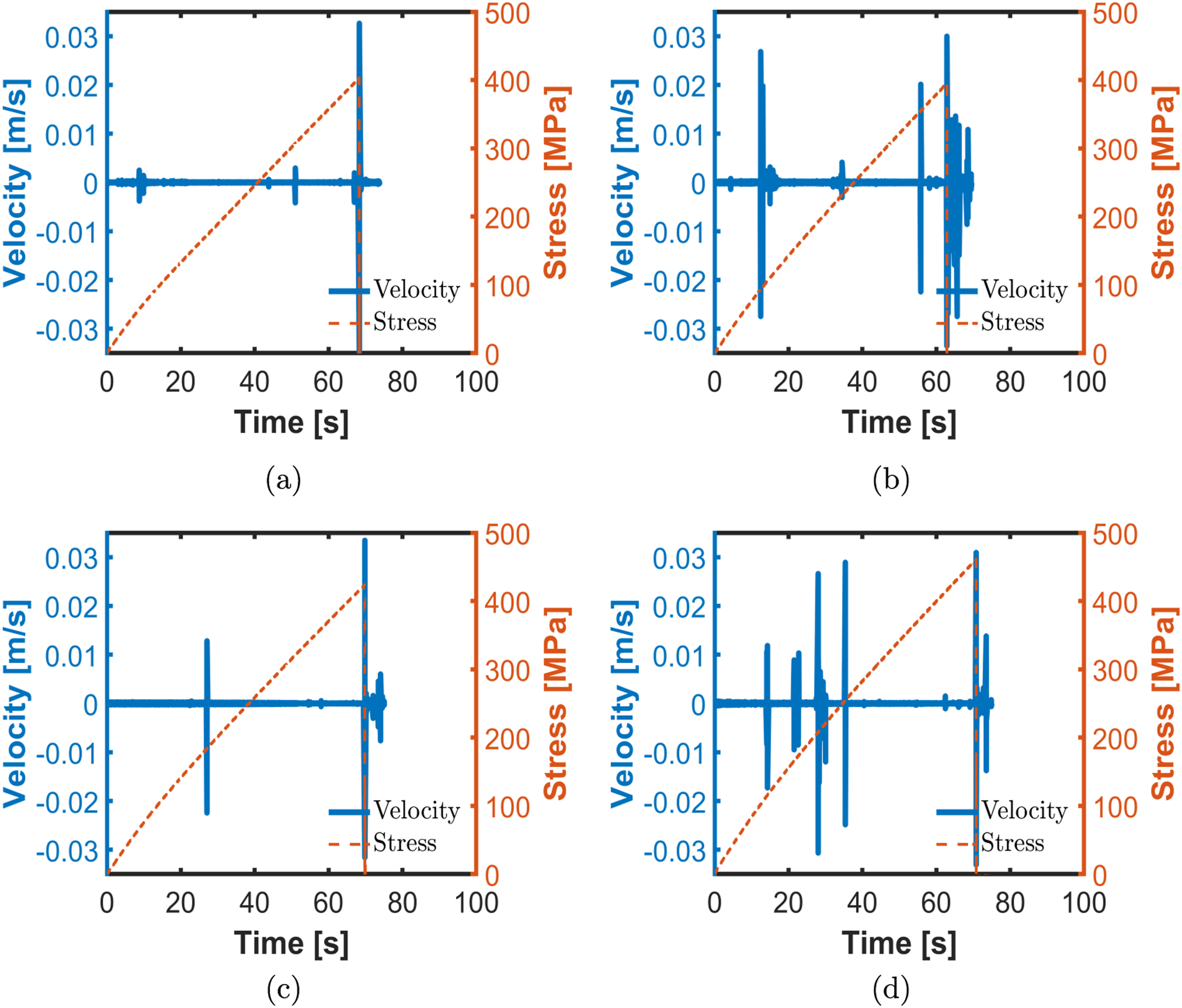
Unlike standard tensile tests, the AE density remains relatively constant, based on the visual impression of the graphs, in the case of OH tensile tests, as indicated in Figure 13. Referring to the AE measurements and the investigated damage mechanism by Furtado et al., 48 the mechanism involving the stress being distributed away from the hole into the undamaged regions for laminates with higher thickness can be confirmed. Additionally, this stress redistribution and stress relaxation around the hole, where stress concentration is significantly high, contribute to a reduction in the evolution of premature damages, as observed in the reduced AE measurements. It is also interesting to note that the final damage in the thinner laminate, with the predominant damage pattern being matrix cracking and fiber failure, is similar to that of tensile tests. In contrast, in the case of thicker laminates, it is associated with the occurrence of extended cracking and delaminations, as depicted in Figure 11.
Standard compression test
Figure 14 shows the compressive test results of the selected unnotched test specimens for TP laminate lay-ups, as presented in Table 1. Stress-strain curves of standard compression tests for (a) 50 μm, (b) 100 μm, (c) 150 μm, and (d) 200 μm ply-thickness laminate.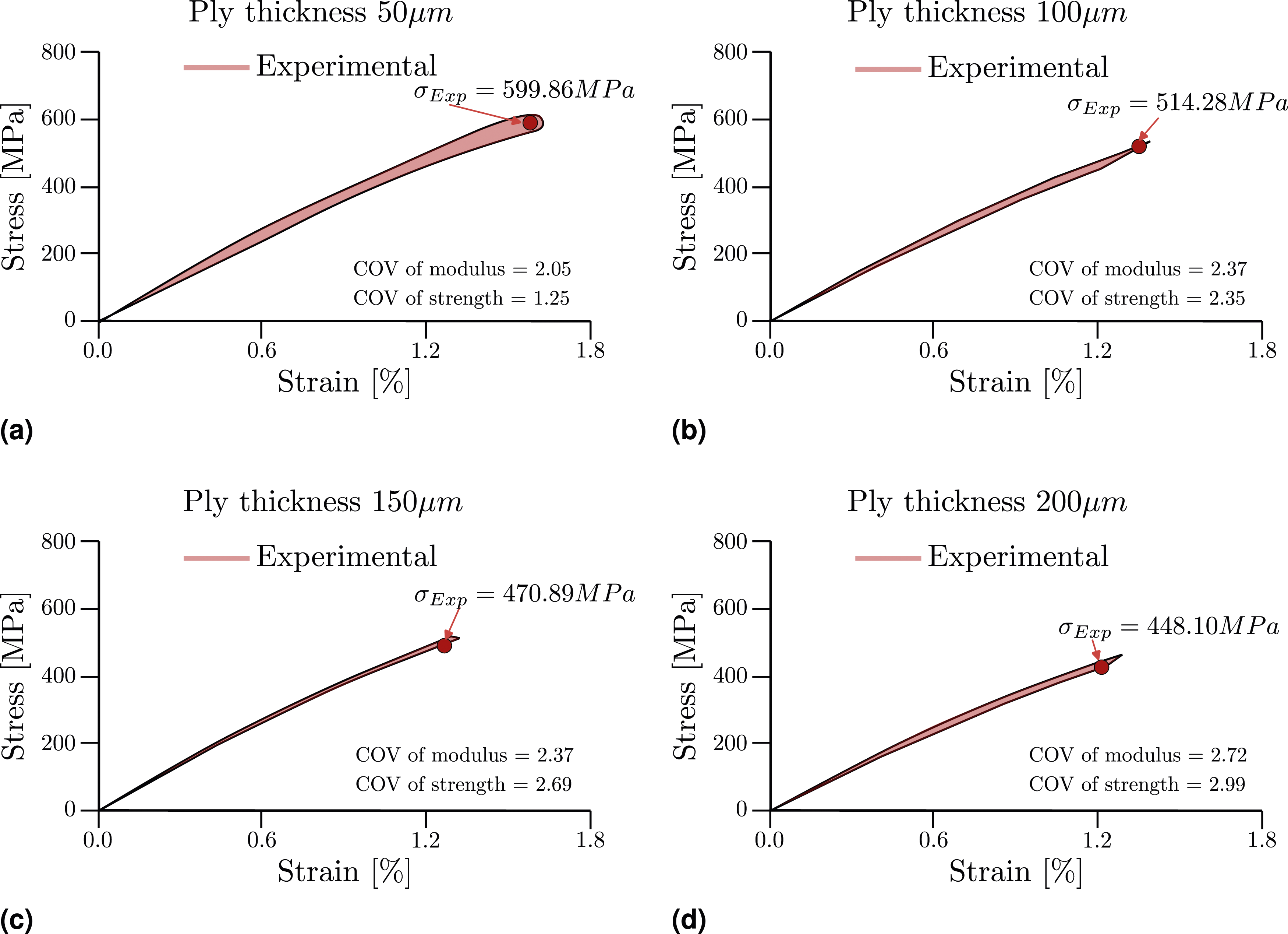
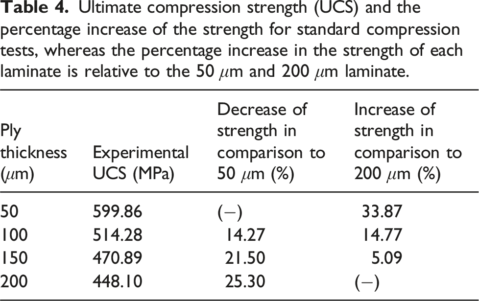
Ultimate compression strength (UCS) and the percentage increase of the strength for standard compression tests, whereas the percentage increase in the strength of each laminate is relative to the 50 μm and 200 μm laminate.
Damage patterns for specimens (side view) with progressive variations of layer thicknesses under standard compression tests are shown in Figure 15. It is observed that the predominant damage in the 50 µm laminate involves matrix cracking and fiber fracture, with fewer occurrences of delamination between the blocks of plies compared to thicker plies. Moreover, delamination between each layer is not highly prevalent. The limited evolution of delamination may have contributed to enhanced strength, as observed in the aforementioned tests. In contrast, the thick ply laminate shows a higher prevalence of delamination compared to the TP laminate. Damage pattern for the specimen (side view) with the progressive variation of layer thicknesses under standard compression tests (The damage pattern is not recorded under the same load).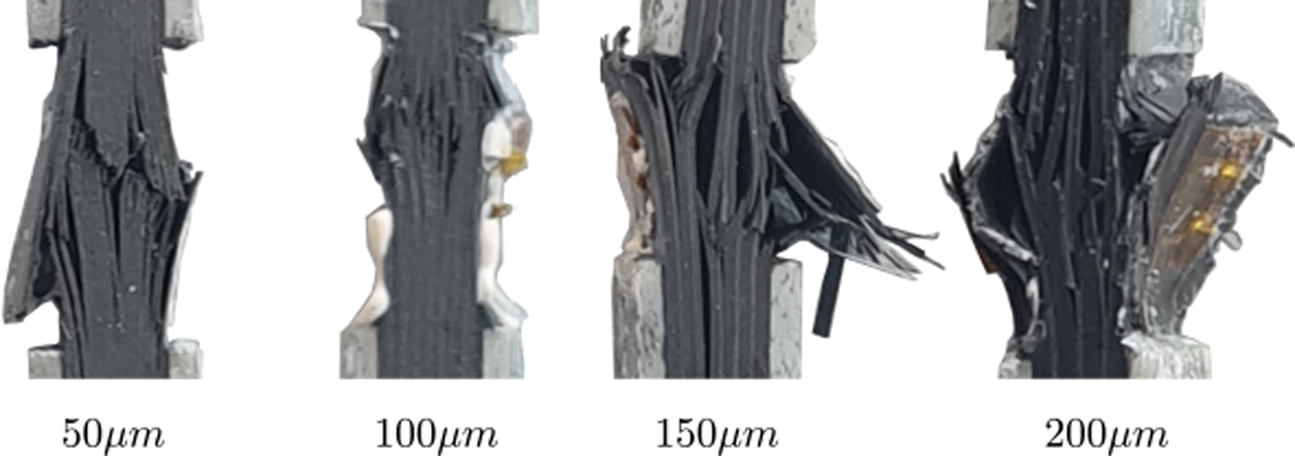
AE measurements were not conducted due to limitations posed by the test fixture and the gauge length, which is only 13 mm and is mainly covered by the strain gauge. The short gauge length was implemented to mitigate the global buckling of the specimen. However, based on the observed strength reduction pattern, we can infer a similar premature damage behavior as seen in the OH compression tests in the next section. Performing AE tests in such a test configuration is significantly challenging and would be considered the scope for future research.
Open-hole compression tests
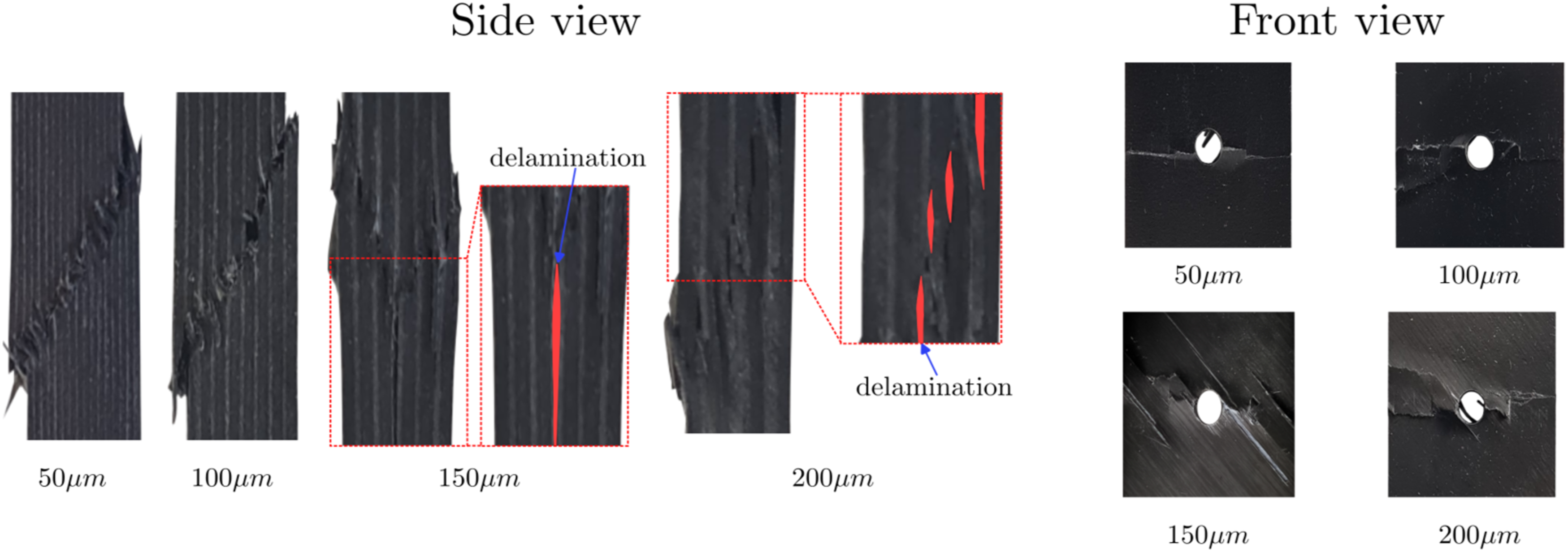
The results of the OH compression tests for the TP laminate lay-up described in Table 1 are depicted in Figure 16. It was noted during these tests that the overall strength characteristics of the laminate followed a pattern similar to that observed in the tensile tests (without a hole). This observation confirms that thinner laminates display higher OH compressive strength in comparison to their thicker ply laminate. The test fixture is designed specifically to minimize global buckling, as shown in Figure 5; however, it does not prevent local buckling or ply buckling at the layer level (see Figure 17). It is evident that the distribution of local buckling affects the OH compression strength. For 150 μm and 200 μm laminates, local buckling of laminates has been noticed locally at the 0° layers. Interestingly, this local buckling does not propagate to all layers until the final failure. Instead, localized buckling increases between adjacent 0° layers, leading to matrix failure and inter-fiber damage initiation. Referring to the figure (front view), localized buckling at layers propagating along the width might have caused stress concentration around the hole for the 150 μm and 200 μm laminates. This stress concentration and inter-fiber failure, leading to delamination, might be the reason why the OH compressive strength reduces with an increase in ply thickness. Similar observations are also mentioned in Takamoto et al.
54
However, for thinner plies (e.g., 50 μm and 100 μm), the observation indicates that ply local buckling might have occurred in TP layers, expanding across all layers and facilitating kink-band areas. As a greater number of layers are affected by local buckling before the ultimate failure, stress redistribution uniformly occurs to all layers around the hole. The ultimate failure at 50 μm and 100 μm is primarily due to fiber compressive failure, resulting in a localized band of fiber fracture. Similar damage patterns have been observed in the literature.
10
Effective ultimate strength of open-hole compression tests on the selected laminate. Damage pattern for the specimen (side and front view) with the progressive variation of layer thicknesses under OH compression tests.
Results revealed that the increase in ply thickness contributes to local fiber/matrix failure and delamination, thereby reducing the OH compressive strength. Moreover, in the thinner ply laminate, damage accumulation has been observed very close to the final failure, resulting in brittle failure. The maximum strength of the 50 μm TP laminate was 275.42 MPa, and the final damage occurred quite spontaneously. To gain a detailed understanding of the damage evolution progression, AE analysis was conducted with a progressive increase in ply thickness.
AE test results on OH compression test samples of thickness 50 μm, 100 μm, 150 μm, and 200 μm are illustrated in Figure 18. Before the ultimate failure, minimal acoustic signatures of premature damage events have been observed for 50 μm, as depicted by spikes in the blue curves. This contributes to the higher effective strength of the TP laminate compared to conventional or thicker laminates. As illustrated in Figure 18, the AE density for the 100 μm ply thickness is higher than that of the TP laminate (50 μm). As a result of localized premature damages, the compressive strength has been reduced to 240.65 MPa. Furthermore, with the increase in ply thickness to 150 μm, there is an evident increase in the evolution of localized damages. As mentioned earlier, these can be attributed to localized matrix failure and the accumulation of delamination. With a further increase in ply thickness (200 μm), the strength experiences a further reduction, dropping to 224.90 MPa. This reduction can be attributed to the stress concentration around the hole and the increased occurrence of premature damages, a trend evident in the elevated AE density, as shown in Figure 18. AE results on OH compression samples with the thickness of (a) 50 μm, (b) 100 μm, (c) 150 μm, and (d) 200 μm.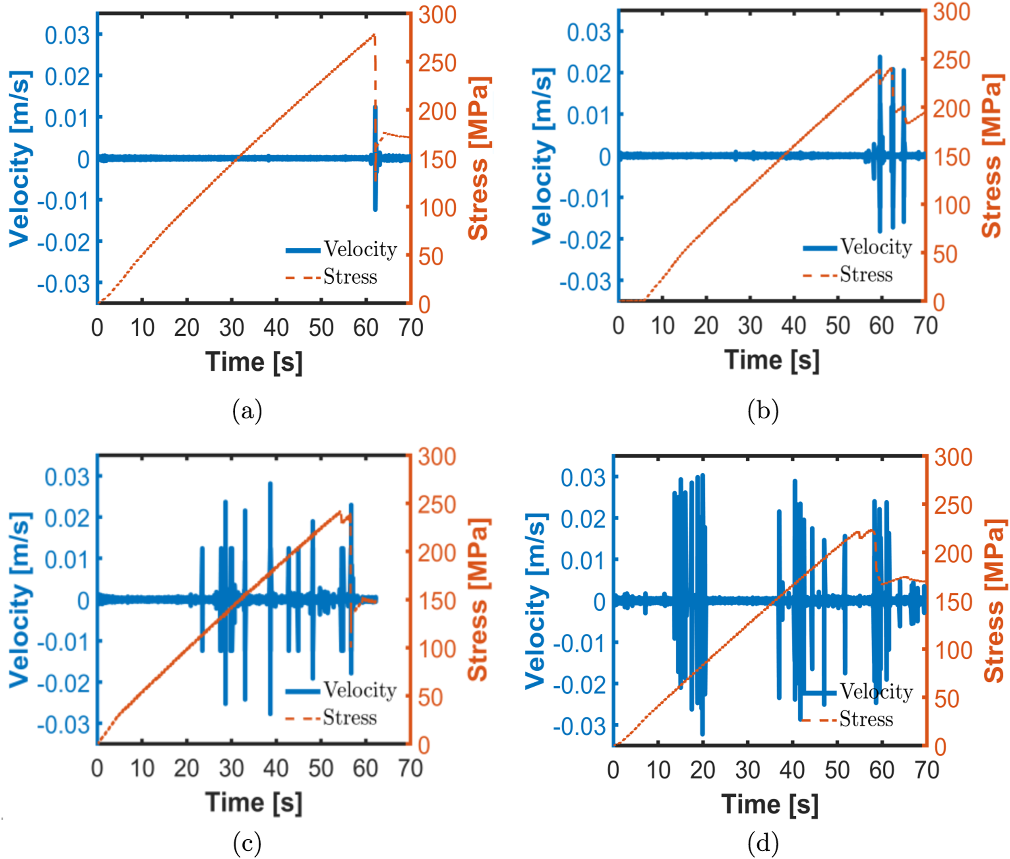
Conclusions
Overview of the tensile and compressive strength of CFRP specimen with and without hole for the quasi-static test campaign.
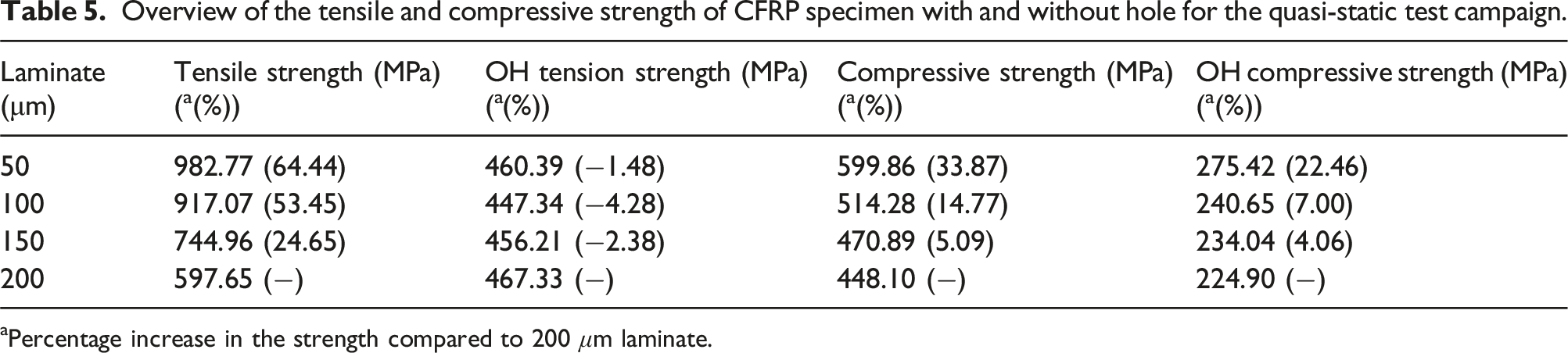
aPercentage increase in the strength compared to 200 μm laminate.
The percentage increase or decrease of strength ( b [%]) with respect to variation in thickness.
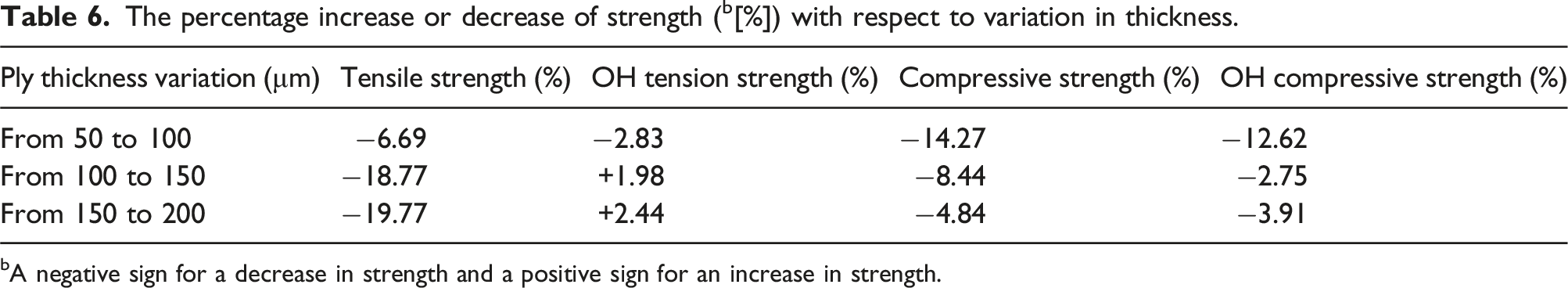
bA negative sign for a decrease in strength and a positive sign for an increase in strength.
Furthermore, as a future scope, this investigation may be extended to evaluate the fatigue life behavior, specifically considering the influence of ply thickness on the evolution of damage under cyclic loading. Based on the results, the contactless AE approach exhibits significant applicability in the evaluation of the initiation and evolution of the damage events. The approach may also be used to determine the residual strength of the composite based on AE density. Additionally, the characterization of the damage mechanism by this approach 55 may also contribute to the modeling of the stiffness degradation of the laminate, considering the thickness of the sublaminate.
Footnotes
Acknowledgments
The authors would like to acknowledge the funding support by the Deutsche Forschungsgemeinschaft (DFG, German Research Foundation) under the Excellence Strategy-EXC 2163/1- Sustainable and Energy Efficient Aviation (SE2A)-Project-ID 390881007.
Declaration of conflicting interests
The author(s) declared no potential conflicts of interest with respect to the research, authorship, and/or publication of this article.
Funding
The author(s) disclosed receipt of the following financial support for the research, authorship, and/or publication of this article: this work was supported by the Deutsche Forschungsgemeinschaft; 390881007.
Data availability statement
All necessary data to replicate the findings are provided within the manuscript. Additional experimental data from AE may be made available on request.
Note
Appendix
A characterization campaign was conducted to assess the tensile, compressive, and shear material properties of respective 50 μm UD laminate. A characterization campaign was performed to evaluate the tensile, compressive, and shear material properties of 50 μm respective UD laminate. Tensile properties were determined according to ASTM D3039, while compressive and shear properties were assessed following ASTM D6641 and ASTM D7078, respectively.
Lamina level properties.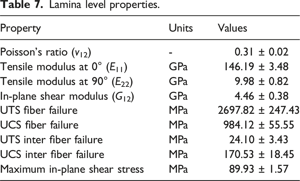
Property
Units
Values
Poisson’s ratio (v12)
-
0.31 ± 0.02
Tensile modulus at 0° (E11)
GPa
146.19 ± 3.48
Tensile modulus at 90° (E22)
GPa
9.98 ± 0.82
In-plane shear modulus (G12)
GPa
4.46 ± 0.38
UTS fiber failure
MPa
2697.82 ± 247.43
UCS fiber failure
MPa
984.12 ± 55.55
UTS inter fiber failure
MPa
24.10 ± 3.43
UCS inter fiber failure
MPa
170.53 ± 18.45
Maximum in-plane shear stress
MPa
89.93 ± 1.57