
Abstract
This study focuses on the development of an advanced high heating rate thermobonding process for the manufacture of preforms and the metrological characterisation of the process. The process involves passing hot air, driven by pressure differential, through a textile stack consisting of several plies of a quadraxial fabric coated with a binder. Heat is transferred into the stack and into the binder by forced convection, melting the binder. The process is used in the same way to cool the stack and binder so that the plies are bonded together. The pressure differential compacts the stack. The comprehensive methodological characterisation of the process includes first determining the air permeability of the stack and thus the volume flow of air as a function of the number of plies stacked. Further characterisation focuses on a comprehensive determination of the heating behaviour in the individual plies as a function of time, using thermocouples and thermal imaging to determine the temperatures of hot air and textiles. These are compared and related using a mathematical approach as different values have been found. The results indicate high heating rates, reducing process time by at least 85% compared to previous binder activation methods. In addition, the cantilever method assesses the flexural stiffness of the processed stacks and shows a twofold improvement in bond strength compared to uncompacted stacks. Results and discussions include orifice based volume flow determination, thermography calibration, mathematical modelling, stiffness of bonded textile plies, process comparison, process control and potential energy savings.
Keywords
Introduction
The series production of continuous fibre-reinforced polymer (FRP) components with small to medium dimensions by means of Liquid Composite Moulding (LCM) processes, such as Resin Transfer Moulding (RTM) or Vacuum Assisted Resin Infusion (VARI), is based on formed semi-finished fibre products that are referred to as preform.1–11 The process steps for manufacturing a preform mainly comprise production of flat fabrics (e.g., woven or multiaxial non-crimp fabrics in rolls) and their CAD-supported preparation as single flat layers that are stacked on top of each other. The following main step is the draping or forming of the multi-layer stack into the desired three-dimensional, near-net-shape geometry. Forming by means of presses and associated tools12,13 or continuously operating processes for the production of profile-shaped preforms are common process routes.4,14,15
The use of binders to fix the preforms after forming is essential to ensure retaining the formed 3D shape during further processing.16,17 The preforms can be stored until further processing or, if the processes are directly chained, they can be transported to the next process step, e.g. by automated gripping, conveying systems 18 or manual processing. The preforms should therefore provide a high level of inherent stability in order to withstand tensile, compressive, flexural, and shear forces. This can be influenced by the chemical and physical composition and, in particular, by the amount of binder used, as well as by the processing and compaction of the fabric itself.12,19,20 The binder must also absorb the resetting forces that arise when originally flat textile layers were deformed. 21 In the aerospace and automotive sector often powdered binders are area-wide or locally applied to the fabric surfaces in advance or inline. 12 The powdery binders are usually applied in the form of granules, melts or dispersions 4 with a 0.5 to 3.0 weight percentage of the grammage of the fabric.4,12,22
A typical thermobonding process comprises the steps scattering binder onto the fabric, heating and melting the binder and then cooling to bond the binder to the fabric.4,5,22 Alternatively, nonwoven fabrics made of thermoplastic fibres are used as binder and inserted between the textile stacks. 7 Thermoplastic or hybrid yarns, which are incorporated directly into the fabric, are also a possible binding agent. 12 All these binder systems are activated during preforming while being converted from a solid to a molten state (activation) and vice versa by thermal processes before, during and/or after forming. After cooling, the transition to the solid state takes place and the stacked fabric plies bond together. Depending on the selected system, the binders are activated at temperatures of approx. 40°C to 160°C.23,24
Studies have investigated the heat transport from an energy source to the binder for its activation using the principles radiation, conduction and convection,9,12,22,25,26 which are also used in industry. 4 Other possible methods include mechanical activation using ultrasound and electrical activation using resistance heating or electromagnetic induction. However, the latter is applicable to conductive materials such as carbon fibres only.4,22,23 In particular, ultrasonic activation provides fast process times of less than 4 s with a stack of up to 10 fabrics. However, high pressure force (e.g., 6 MPa) is necessary. 27 A large surface area to be activated leads to substantial requirements for a partly or complete fixation of complex 3D preforms.
Summary with the differentiation by principle of developed and investigated heating processes (bot. meaning bottom).
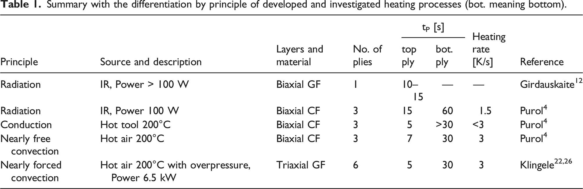
Purol 4 has developed and experimentally tested a continuous forming process with activation of binders for fixing profiled preforms. Process times between tP = 7 s for the top ply and tP = 30 s for the bottom ply were achieved using hot air (principle is nearly forced convection) for a biaxial fabric made of carbon fibres (CF) with three plies on top of each other. The results of the radiation-based analysis from Purol 4 and Girdauskaite et al. 12 show that the radiation affects the top ply directly, while the bottom ply requires a very long heating time tP = 30–60 s. IR radiation cannot pass through the glass fibre (GF) or CF material. Heat is transported by almost free convection via the air between the textile layers, plies, fibres, and filaments as well as by heat conduction between the fibres. Klingele 22 (and also Klingele et al). 26 uses a robot with an end effector that grips a stack of textiles and blows hot compressed air at them to heat the binder. After approx. tP = 30 s, the bottom ply reaches 90°C, which corresponds to a heating rate of max. 3 K/s.
So far, only flat preforms have been used for heating analyses and no studies have been carried out for three-dimensional geometries. Additionally, in above processes the preforms are heated prior to forming, which leads to a cooling between the heating and the forming steps. There is therefore still a need for processes that enable the binder to be activated and cooled immediately during or shortly after forming using the same process technology. Deficits arise in particular due to long process times or low heating rates, which affect the cycle time of the entire process chain for the production of fibre-reinforced polymer composites.
Aims and scopes of the study
The aim of this research work is to develop an advanced thermobonding process for the production of textile preforms that drastically reduces process times, can be used for any 3-dimensional geometries and, in principle, has further clear advantages compared to the processes already shown. In this process, hot air is drawn through a stack of fabrics as a pressure difference between the top and bottom of the stack causes the hot air to flow. The stack consists of up to 10 blanks of a quadraxial fabric. Each blank is pre-coated on one side with a binder. The process transfers heat from the hot air to the binder and to the stacked fabrics by forced convection. Both the binder and the fabric are heated, whereby the binder melts and becomes sufficiently tacky to bond the stacked plies. After this activation of the binder, cold air is drawn through the stack, cooling the binder and the fabric to bond the plies together. The fabric stack is compressed by the pressure difference to the ambient air, which is expected to make the laminate adhere more effectively to each other.
In order to characterise the air flow, a pressure difference and volume flow measurement system is developed. The work serves in particular to provide fundamental process parameters. The intention is to determine the air permeability as a function of the number of stacked plies in order to obtain information on the suitability of the process for processing many plies.
Of particular interest is the determination of the heating behaviour of the binder, e.g., the achievement of sufficient liquefaction. A method is described in which thermocouples are located between the plies. This allows the resulting temperatures in the stack to be determined and initial position-dependent information on heat transfer to be obtained. The thermocouples are prepared for dynamic recording by preparing them to have a lowest possible thermal mass. In order to capture the temperature of the fabrics, calibrated measurements are carried out using thermography. Thermography is an imaging technology for contactless measurement of the surface temperature of objects and is an important method in all areas of science and technology, 28 e.g., in non-destructive testing 29 or in determining thermal insulation of coated textiles. 30 In this work, it is presumed that this method indicates the surface temperature of the fabric and indirectly also the temperature of the binder. However, the challenge here is to use the method to record the temperatures within the stack. This is made possible by a methodical procedure in which the process is interrupted after a defined time and thermographic images of each individual ply are recorded. However, it is currently not possible to determine the binder temperatures using the available temperature measurement principles, e.g., with thermocouples and thermography as a direct measurement method, as the binder quantities are very small compared to the fabric. Probably the binder has at least the same or even a higher temperature than the fabric.
The cantilever bending method is used as a quantitative measure of the inherent stability of preforms produced using the process. In order to demonstrate the positive influence of compaction on the bending stiffness, compacted stacks are compared with non-compacted stacks and the process times are related for free (without pressure) and forced (with pressure and thus with hot air flow) convection. The last section of the experimental setups describes the initial conditions of that through-air thermobonding process and the experimental procedure for determining all of the measured values.
The results obtained are presented and discussed in detail. This initially includes the preparatory work for calibrating the infrared thermography for the case of temperature-dependent non-linearities and the identification of the flow behaviour of air and the air permeability of the stacked fabrics. In the main part, the experimentally determined heating behaviour and thus the temperatures of fabrics and air are presented as a function of time and discussed in detail using two cases “with pressure” and “without pressure”. These methodical investigations consider whether the fabric and hot air are in thermal equilibrium during the process and indicate in particular the resulting process times. The discussion of the results also includes a mathematical approach that was developed to relate the temperature curves measured with the thermocouples to the thermographic measurements, which are only available at certain points in time. Finally, the bending stiffness achieved and thus the success of the process is compared depending on the two cases in comparison to unprocessed blanks and the mechanical properties are discussed extensively. The developed process is than compared with the current processes shown in Table 1 and further benefits such as suitability for 3-dimensional geometries, process control and potential energy savings are discussed.
The last section summarises the most important results from the developments and investigations and provides recommendations for the modelling of the process using simulation.
Materials and experimental setup
Materials
The quadraxial non-crimp fabric HiMax™ FGE109
31
(manufacturer: Hexcel Corporation, USA) is used. The fabric is made of E-Glass with +45°/90°/−45°/0° fibre orientations and has an area weight of mA = 627 ± 32 g/m2. The stitching yarn consists of textured polyester yarn (PES). The melting range of the PES yarn is approximately 255°C–265°C.
32
The thickness of the fabric is t = 0.75 mm (uncompressed), the density of E-Glass is approx. ρGF = 2.6 g/cm3. Since the density of air ρAir is much lower than the density of E-glass and can therefore be neglected, equation (1) results in a porosity of the fabric of ϕ = 0.68 (uncompressed), which means that the fabric consists of approx. 68 % air and is permeable or porous. Views of the fabric FGE109 - from top (left), from bottom with coated binder particles (middle), close-up of the binder (right).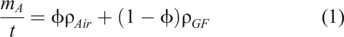
Development and design of the through-air thermobonding process
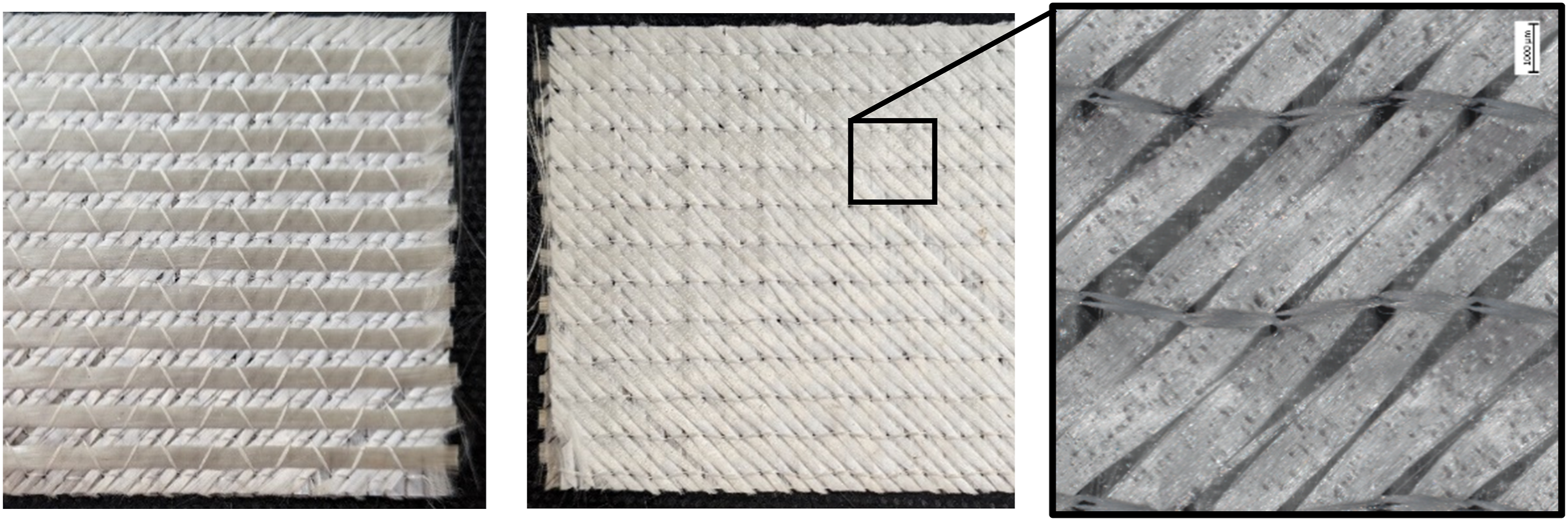
The investigations were carried out using a through-air thermobonding device developed in-house. The actual design and further details are shown in Figure 2. According to preliminary considerations, the device consists of a (1) sheet metal housing with a circular cross-section, into which hot air is injected tangentially. The hot air rotates in the housing, which is intended to create a largely homogeneous temperature field in the entire housing (2). Two hot air tools HL1920 E (supplier: Steinel GmbH, Germany) with a power of 2 kW each are used for hot air generation and injection. The temperature setting is variable and adjustable between 80°C and 600°C. Depending on the adjustments and air temperature, 8–10 L/s of hot air are provided. Design of the developed through-air thermobonding device as 3D-CAD representation (left), image of the real set-up (right) principle of the process and applied compressor (middle).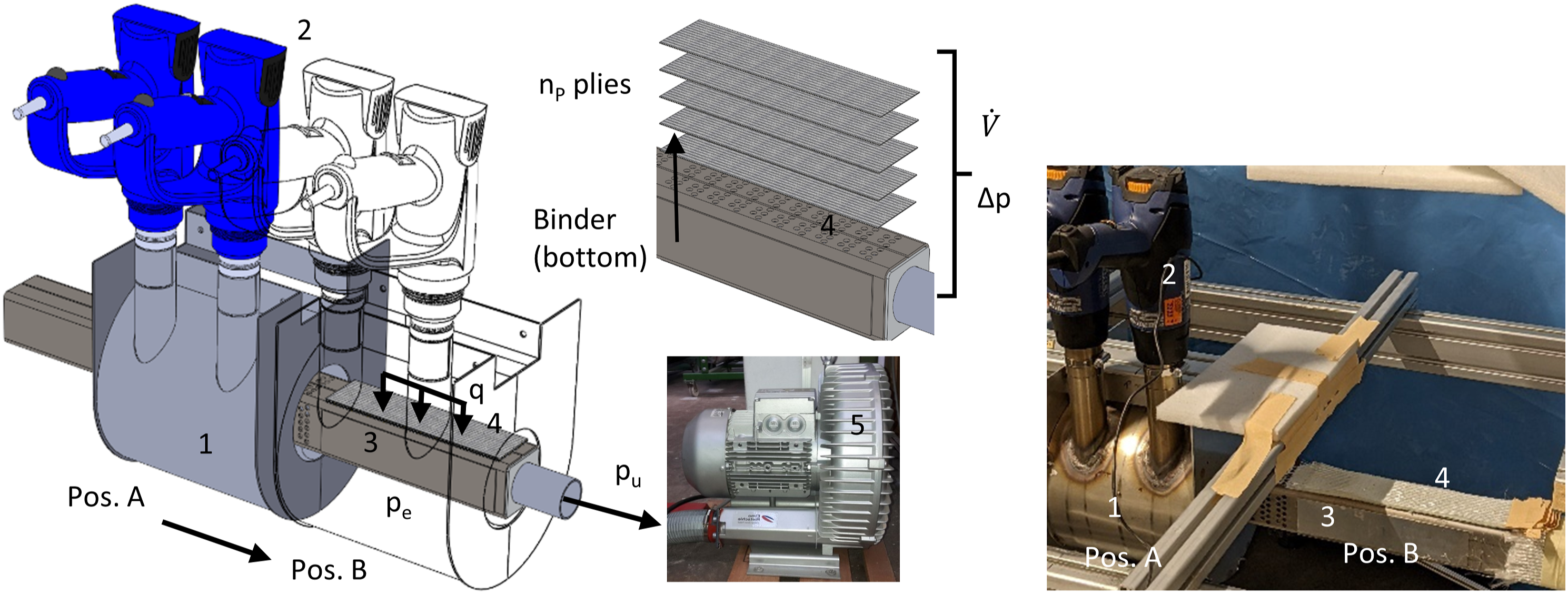
The housing is laterally moveable between the two positions A and B. Pos. A indicates the insertion position of the samples, whereby the samples are processed on top of each other as a stack with nP plies, Pos. B indicates the processing position. Inside the housing, there is a (3) core with a support area, on which (4) n plies of fabrics can be positioned. At Pos. A. the core is connected to the (5) side channel compressor 2BH1 600-7AH26 (supplier: Gardner Denver, USA) by a pipeline with a self-built, integrated pressure measuring system and possibilities to control pressure, flow mass and volume rate, respectively. The compressor generates an underpressure pu up to 325 mBar compared to ambient pressure pe at an applied three-phase current of 50 Hz with a maximum electrical power of 3 KW.
The support area (4) for placing the stacked plies has an arrangement of 100 holes each with a diameter of 5 mm. Through the holes, the hot air is drawn through the plies with a volume flow rate 
This assumes that pe is homogeneous as the ambient pressure pu depends on the number of stacked plies or the thickness of the stack, adjustments of the compressor and in the pipelines in between.
Pressure measuring and volume flow rate determination
An important part of the measurements is the determination of the air permeability of the stacked plies, the pressure difference and the resulting volume flow rate 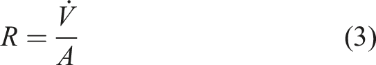
For this reason, a measuring system for the required values was developed and integrated into the through-air thermal bonding device. Figure 3 shows the entire flow system of the device from the core with support area (4) to the side channel compressor (5). A clutch (6) enables pulling apart the pipes and thus to interrupt the volume flow. An additional branching with a restrictor (7) specifically allows a secondary air volume flow rate Flow and measurement system of the developed through-air thermobonding device.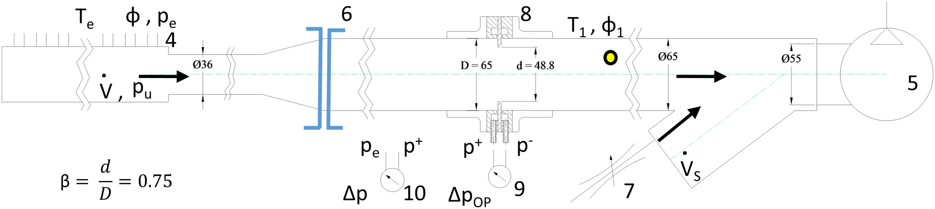
Determination of pressure differences and associated mass flow rates respectively volume flow rates through the thermobonding device is carried out using a self-built orifice plate based measurement system (8). Orifice plates are very commonly applied to measure flow rates of gases and liquids with high accuracy.35,36 The measuring system uses Bernoulli’s principle, which states that an increase in the velocity of the fluid is accompanied by a simultaneous decrease in the static pressure or a decrease in the potential energy of the fluid. The increase in velocity is achieved by narrowing the cross-section, where β = 0.75 describes the selected ratio of orifice diameter d to pipe diameter D.
The value β influences the maximum possible volume flow rate only to a small extent. According to ISO 5167-2 37 , a value of β ≤ 0.75 is recommended. With a small β, the flow and thus the achievable volume flow rate is severely obstructed by pressure drops at the orifice plate. However, a great β reduces the accuracy of the determined values, especially for small volume flows.
The mechanical construction consists of 3D printed flange parts (material: polylactide acid, PLA), a self-made orifice plate (material: aluminium) and glued-in tube connections for the two measuring points p+ and p−. The 3D printed parts are sprayed with epoxy filler to ensure impermeability.
The differential pressure transducer ZS2 (9) (Manufacturer: ZILA GmbH, Germany) is used to measure the static pressure before (p+) and after the narrowing (p−) and in particular the pressure difference ΔpOV. The ZS2 converts the pressure in the range of 0 to 500 mBar into corresponding voltage signals of 0 to 10 V, which was recorded with the data logger USB-6218 (manufacturer: National Instruments, USA) and the corresponding SignalExpress software. Additionally, the ZS2 was also used to read the pressure difference Δp (10).
In order to determine the fluid density ρ1 as a function of fluid temperature T1 and relative humidity ϕ1, the necessary pressure pu is calculated with equation (2). Using the PCE-313A hygrometer (manufacturer: PCE GmbH, Germany), the values T1 and ϕ1 were measured downstream of flow according to ISO 5167-1. Under these conditions and if the orifice plate is designed and installed according to appropriate international standards e.g., ISO 5167-1,
38
volume flow rate 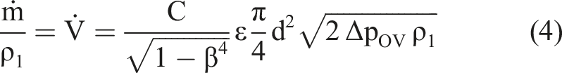
C denotes the coefficient of discharge, 39 which depends on the geometry of the orifice plate and the pressure tapping arrangement. ε is the expansion factor and can only be set to 1 for incompressible gases. 40 Calculations of the fluid density ρ1 as function of temperature T1 and relative humidity ϕ1 as well as calculations of the coefficients C and ε are carried out according to international standards, partly using very complex polynomials and factors. Overall, the calculations according to equation (4) require many steps in connection with specific material data. The calculations to be carried out can be found in ISO 5167-1 38 and ISO 5167-2. 37 Material data and basic relationships are comprehensively described in.40–42
The software tool OriFlowCalc
43
(TetraTec Instruments GmbH, Germany) was used for all calculations. The software, implemented in Microsoft Excel – Visual Basic for Applications (VBA), fulfils all necessary requirements. The input parameters are as follows: − orifice sizing data (d, D, orifice plate type with flange tappings,
37
fluid: moist air), − measured values ΔpOV, pu, T1 and ϕ1, and − standard conditions for the output values.
The output parameters include flow results, e.g., volume flow
Conditions to determine the flow characteristic of the system.
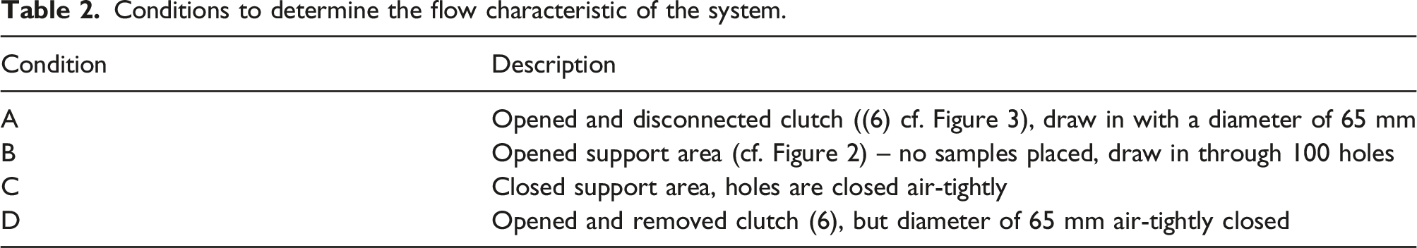
Finale measurements were carried out on 1 to 10 stacked plies of the samples and were intended to provide information on the suitability of the process for activating the binder and fixing preforms consisting of a large number of fabric plies and layers.
Temperature measurement by means of thermocouples
Thermocouples are first prepared in order to measure the temperature curves over time in the fabric plies. Configurable thermocouple extension cables from reel type KX - 7/0.2 mm (K-type, nickel-chromium/nickel with a sensitivity of 41.0 μVK−1, supplier: TC Direct, Germany) were applied. The cable consisted of seven thin single wires with a diameter of 0.2 mm (stranded wire) per electrical pole. Six of the seven wires per pole were snipped off and the remaining wires of each pole were welded together. The thermocouple produced in this way had a very low thermal mass and allowed the measurement of dynamic temperature changes. The functionality and linearity were validated with the aid of a laboratory furnace and met all requirements arising from DIN EN 60584-1 Class 2 standard 45 in the range between 0°C and 350°C.
Four of these thermocouples – one in every ply as shown in Figure 4 were inserted into the four interspaces of the stack consisting of five plies at position M shown in Figure 6. The position M was directly above one of the holes through which hot air flows. During the experiments, the temperatures TTE1, TTE2, TTE3 and TTE4 were simultaneously recorded with the thermocouple data logger TC-08 (Pico Technology, United Kingdom) and the corresponding software PicoLog. In addition, a manually readable, thermocouple based thermometer G1200-E3 (GHM Messtechnik GmbH, Germany) was used to measure the hot air temperature Te in the housing at a short distance above the textile stack (see Figure 6). The textile stack was prepared as described, then fixed as a compact and repeatable to handle stack, and used for all measurements. Thermocouple applied to the FGE109 sample ply 2 (top view, 0° fibre orientation, surface without binder).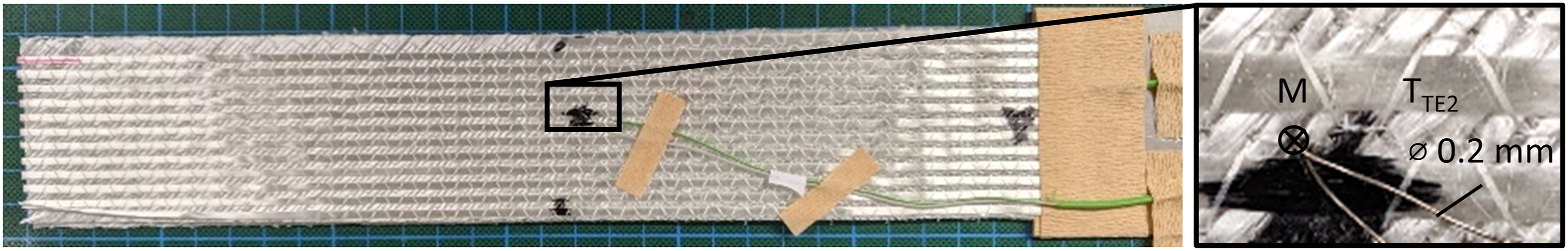
Temperature measurement by means of thermography
The thermography28–30 was used for non-contact determination of the temperatures of the individual plies in the stack. The main interest was to measure the surface temperatures of the plies and compare them to the measurements with the thermocouples. Thermography allows also visualisation of the 2-dimensional temperature field each ply, which suggests that the data is also likely to provide local heat transfer and flow conditions. However, the use of thermography requires a methodology to be able to determine the temperatures in the stack by interrupting the process after a set time and allowing the temperatures of each individual ply to come into view.
The infrared camera (IRC) PYROVIEW 380L (Dias GmbH, Germany) was used. The IRC detects thermal radiation in the spectral range from 8 μm to 14 μm and is therefore suitable to display surface temperatures in the range from 0 to 400°C. The sensor of the IRC consists of an uncooled microbolometer array with 384 pixels × 288 pixels. The control and display application PYROSOFT® Professional was used to process the image data. The manufacturer specifies a measurement uncertainty of 2 % of the measured value in °C.
The IRC was installed in position B at b = 375 mm above the support area of the textile stack (4) as shown in Figure 5. Based on the imaging scale, each pixel corresponds to a sample area of 0.52 × 0.52 mm2. Non-woven fabrics with a thickness of 10 mm were applied at critical points to avoid reflections of the heat radiation. Due to the mounting of the IRC, measurement was only possible when the housing was in position A. Arrangement of the infrared camera and measuring area.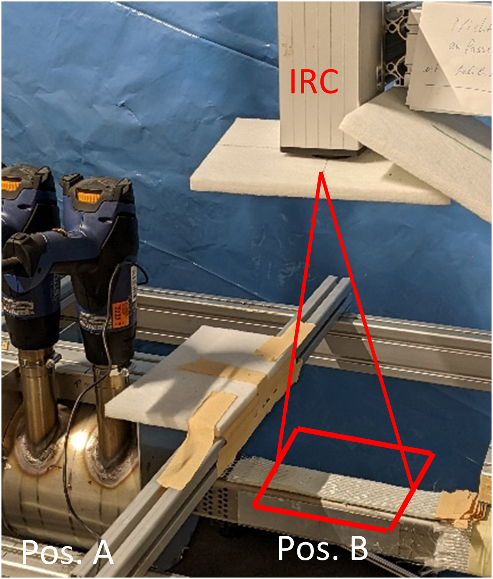
The most important factor while measuring temperatures with the help of thermography is the emissivity ε of the material. It is known that real objects, called grey bodies (ε < 1), emit a lower radiant power than perfect black bodies (ε = 1) at the same temperature. The Stefan-Bolzmann law
46
is therefore usually extended by the factor ε(T) with equation (5), where PR denotes the radiation power, σ is the Stefan-Boltzmann constant and T is the absolute temperature of the body.47,48
The emissivity ε(T) is strongly depending on the material and the temperature. For general glass, values of ε(20°C–100°C) ≈ 0.94–0.91 and ε(250°C–1000°C) ≈ 0.87–0.72 are given. 42 Exact parameters for textile fabrics made of E-glass filaments are not known from literature, e.g. 49 Therefore, the thermographic measurement set-up was investigated and finally calibrated using the sample material FGE109. A pre-set emission coefficient of ε = 0.88 was applied as input value for the internal calculations in the IRC-Software.
Calibration
Firstly, a stack of five plies was heated to eight different, constant reference temperatures in the range of 20 to 280°C. Heating was carried out for a long time of tH = 300 s with the described set-up without pressure (Δp = 0), such that the heat transfer occured by nearly free convection. It is assumed that the top surfaces have the same temperature as the reference temperature of the hot air (measured with the thermocouple Te in the housing directly above the stack) after the long heating time tH. The values determined should match the reference temperatures if linearity is provided.
Image capture in the individual plies
The IRC-Software continuously recorded a video at a rate of 3.2 fps (frames per second). To obtain the temperature image of each fabric ply, plies were removed manually ply-by-ply while the camera recorded continuously. During this process, however, the plies cooled down due to free convection and heat conduction into the fibres. A time of around 2-3 s was passed between the images of each ply. Any deviations due to cooling of the surfaces were ignored in the first instance. For the analysis, the image data was cut out as shown in Figure 6 (IRC-Area) and the temperature value at measuring point M was determined. Positioning of thermocouples (left) and view of the support area with indication of the measuring areas with point M (right).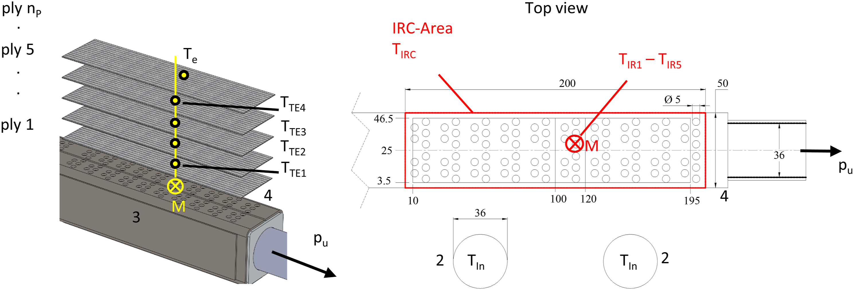
The temperature image data sets TIR1 to TIR5 at point M were compared to the thermocouple temperatures TTE1 to TTE4. The TTE5 temperature was not recorded over time; it corresponds to the approximately homogeneous temperature Te in the housing directly above the top ply.
Determination of the resulting bending stiffness
The cantilever bending stiffness of the bonded and unbonded stack of plies was measured with a standardised procedure according to DIN 53362
50
using the testing device ACPM 200P (CETEX GmbH, Germany). The method is based on placing and moving a sample over an edge. After the sample has been deflected by its own weight up to a 41.5° line, the overhang length is determined. The cantilever test is a common method for determining the bending stiffness of textile fabrics and is also the preferred method in the ASTM D1388
51
standard. The width-related bending stiffness G is determined with equation (6).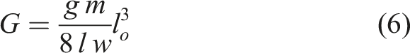
For the experiments carried out here, the width of the samples is w = 50 mm, g is the gravitational acceleration, m the mass, l = 300 mm the length of the samples and lo the overhang length when the 41.5° line is reached. For comparison of the results, the measurements were performed using stacks with the number of plies nP = 1 to 5 on top of each other with the following variants: − “unprocessed”: stacked plies were not processed, were lying on top of each other and were tested unbonded, − “without pressure”: stacked plies were processed with the thermobonding device but temperature transfer was by free convection i.e. without pressure difference and therefore without compaction, − “with pressure”: stacked plies were processed with the through-air thermobonding device by forced convection with the highest achievable pressure difference and therefore compaction of the stack.
Within the “with pressure” variant, cooling was also performed with pressure when the housing was shifted back into Pos. A and thus cold ambient air was transported through the stack. In addition, the bonded ply stack was tested in two positions: “from top” means that 0° warp yarns are at the top, as shown in Figure 4, “from bottom” means that the 0° warp yarns are at the bottom. The term “both” means that the average of the values for “from top” and “from bottom” was calculated. Five specimens of each variant and each number of plies nP were examined and the standard deviation of the mean was determined.
Initial conditions and experimental procedures
For processing and studying the heating behaviour of the stacked plies, the hot air in the housing was set to a temperature of ca. 260°C and preheated with a time of tH = 600 s to ensure constant conditions. The two hot air tools together ((2) in Figure 2) supply approximately
After preheating and placing the stack, the housing was shifted from position A to B for the process time tP, depending on the variant. The experiments to determine the temperatures based on thermocouple and infrared measurement were carried out separately. The temperature measurements based on thermocouples were done simultaneously while the hot air was flowing through the stack. The IRC measurements were carried out as described above, by removing the samples ply by ply after the process time tP and shifting the housing back to position A. During shifting, coupling ((6) in Figure 3) was opened abruptly such that no additional air was transported through the fabric. Within these investigations, five plies were heated and their heating behaviour was examined.
Results and discussions
Calibration of the infrared thermography temperatures
Figure 7 shows the temperature field of the top sample after heating to Te = 79.5°C. The temperature field in the middle of the sample is close to the reference temperature Te at 80.1°C. At the boundaries of the samples, the temperatures are higher at approx. 84°C, which is probably related to the radiation characteristics of the cut E-glass filaments. The temperatures are slightly lower at the right hand side. Openings to the cold ambient air at this point probably lead to temperature deviations during heating. Air heated by convection outside the sample (red dashed lines) is visible. It can be assumed that the heated air distorts the entire measurement image. A pixel-precise detection would only be possible under vacuum conditions. Example of a thermographic image taken from a stack of five samples at a temperature of 79.5°C using the Software PYROSOFT®, red dashed lines according to Figure 6.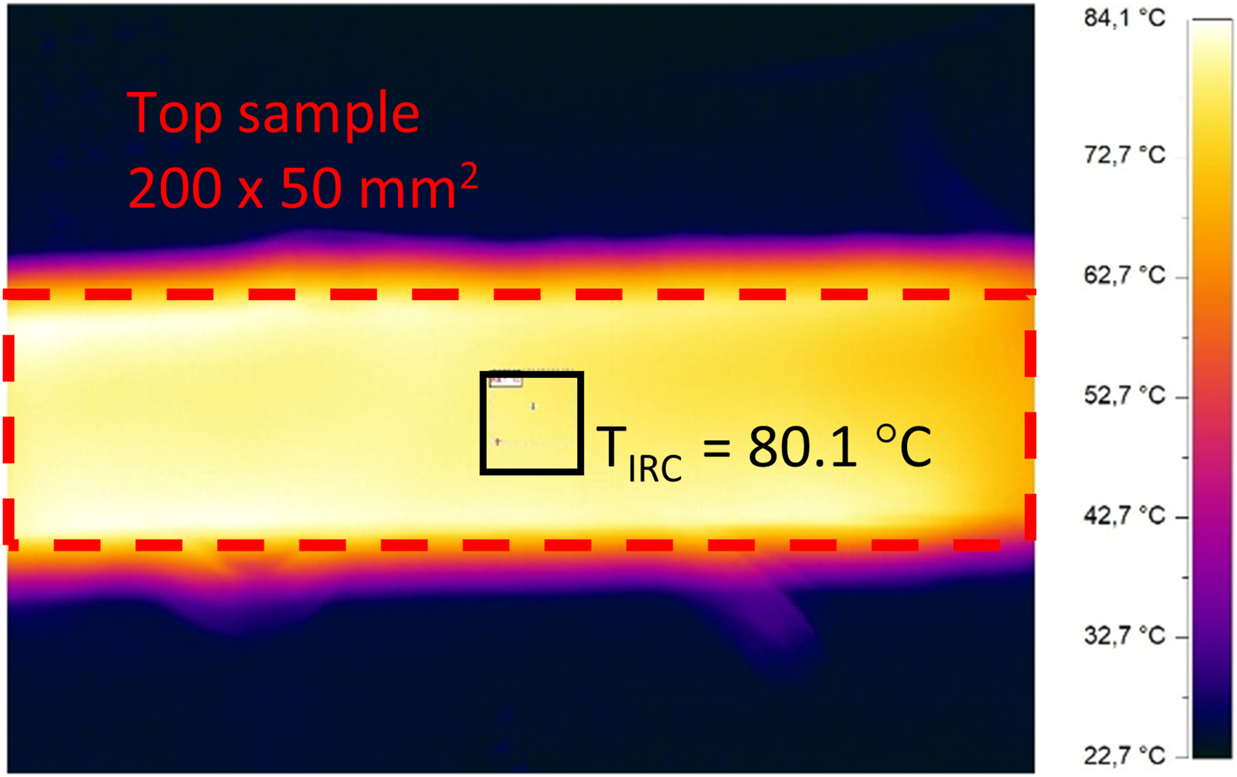
Figure 8 shows the eight single measurements of TIRC and a fit against the reference temperatures Te plotted as angle bisector (index ab) of the coordinate system. With increasing temperatures, there are significant non-linear deviations between the reference Te and the temperature TIRC measured by the IRC. This result can be related to the temperature-dependent emissivity. Nevertheless, the influences of the surrounding air can also be a source. In the range between 50 and 100°C the values agree approximately, which is related to the specific choice of ε = 0.88. Comparison of the reference temperatures Te with the temperatures determined by thermography TIRC and calibration with f−1(TIRC).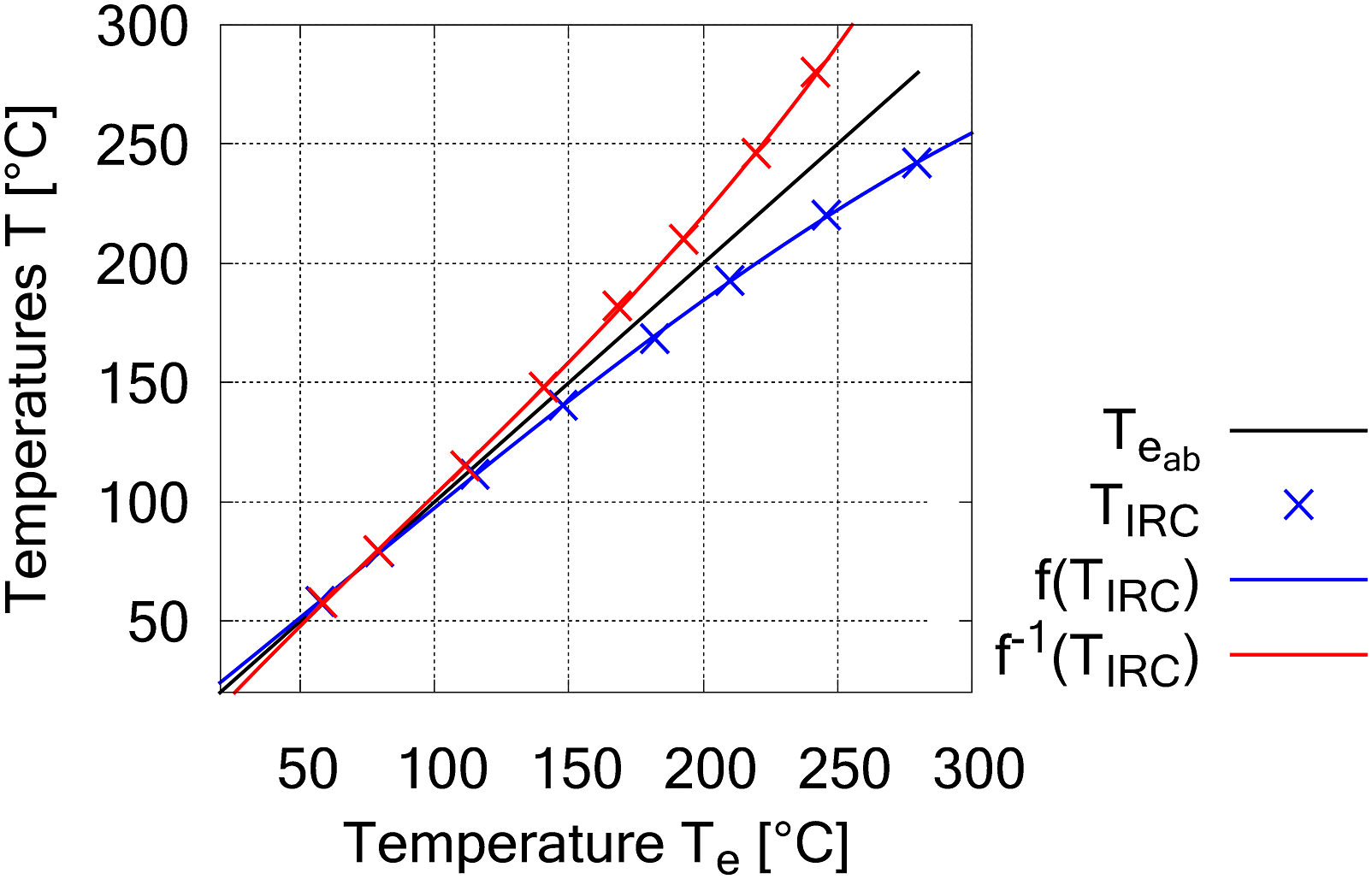
For calibration of the IRC temperatures, the values of TIRC are mirrored at the angle bisector and a third-degree polynomial f−1(TIRC) was calculated with the method of least squares. The polynomial is used to calculate the temperatures of all following IRC images. For this purpose, the IRC image Im is imported into Matlab and processed with equation (7). The image Im
cal
thus correctly displays the reference temperatures in the range of 20°C to 300°C, which ensures that the temperature field in this range is almost independent of material emissivity and therefore calibrated.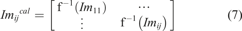
Flow characteristic and air permeability
Figure 9 shows the resulting pressure difference versus the volume flow rate characteristics of the developed flow system in comparison to the specifications of the compressor manufacturer using the conditions in Table 2. There is an approximately linear progression between pressure relative to the ambient pressure pe and corresponding volume of air intake. The graph corresponds very well with the manufacturer’s specifications, but differs in the size of the possible volume flow rate and allows approx. 60 m3/h smaller volume rates. The integrated orifice plate probably causes these deviations by creating a resistance compared to the perfect test conditioning of the manufacturer. The measuring points “1 ply” and “5 plies” are part of the correlation. Comparison of the volume flow versus pressure difference with the compressor manufacturer’s specifications.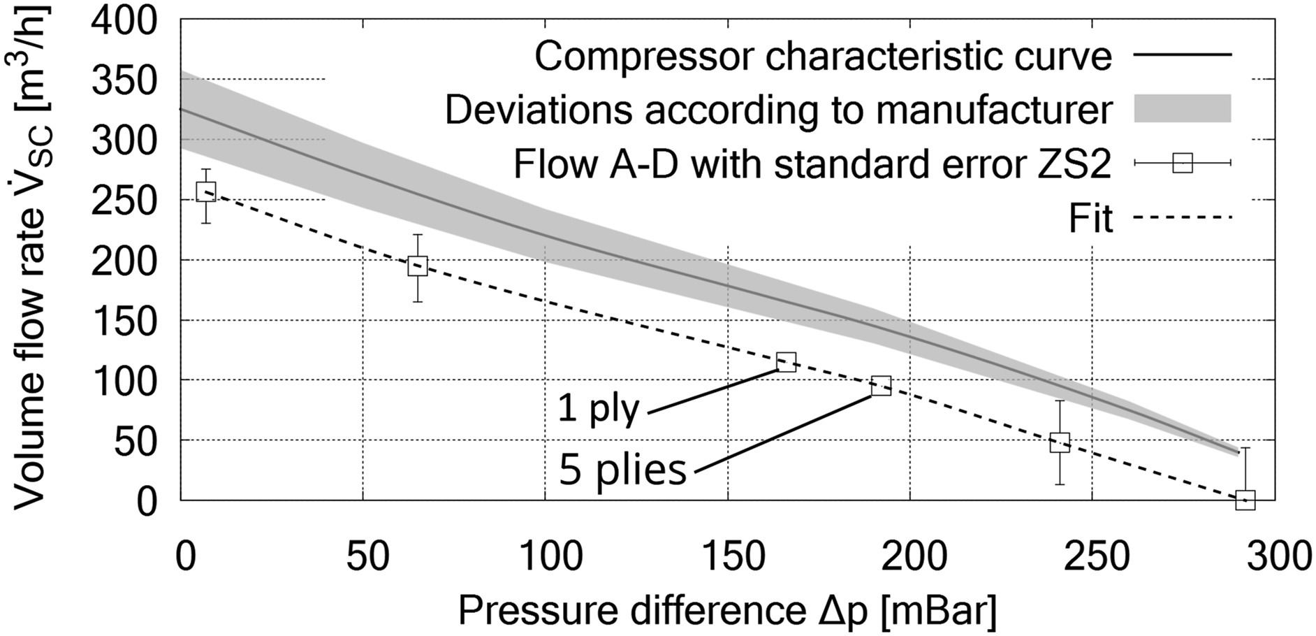
Figure 10 shows the detailed graph with up to 10 plies. Significant changes of the flow rate occur between “1 ply” and “5 plies” while the pressure difference/volume flow rate asymptotically approaches a limit value of 90 m3/h with increasing number of plies. From these results, it can be concluded that the developed through-air flow system does not restrict the number of textile fabrics that can be processed, as long as sufficient porosity of the fabric is provided. Detailed graph of Figure 9 with values as a dependency of the number of plies.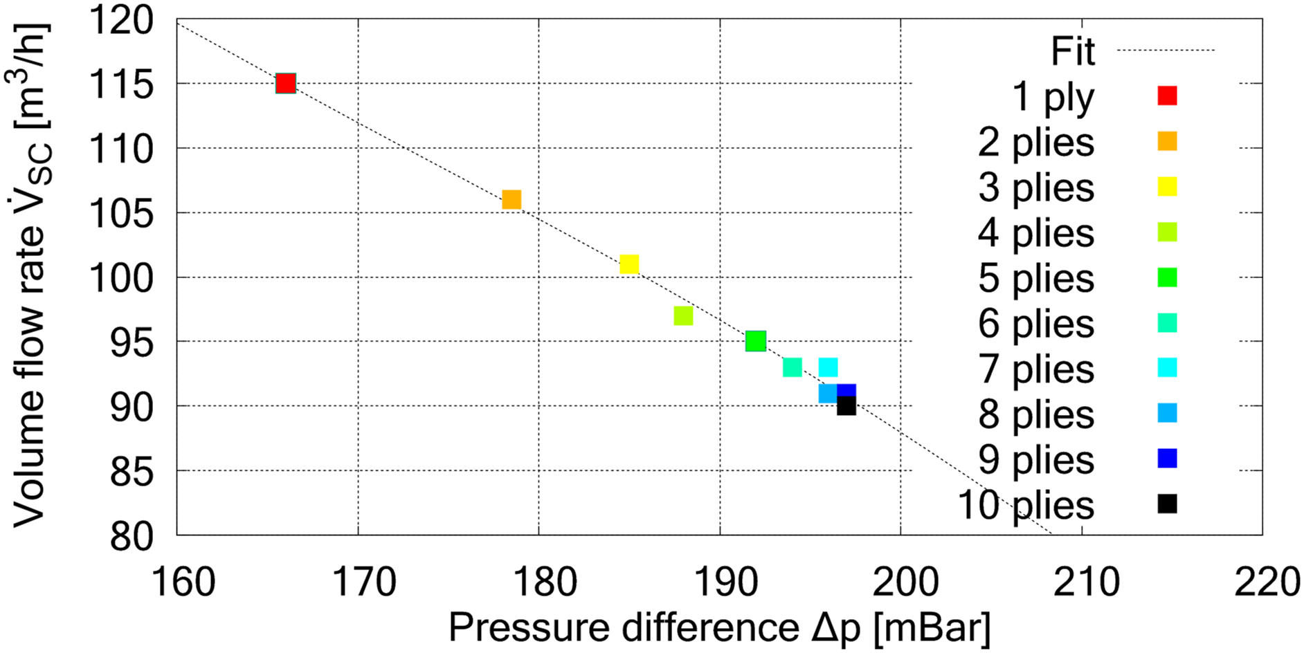
Selected relationships, equivalent force Feff and change of air permeability R.
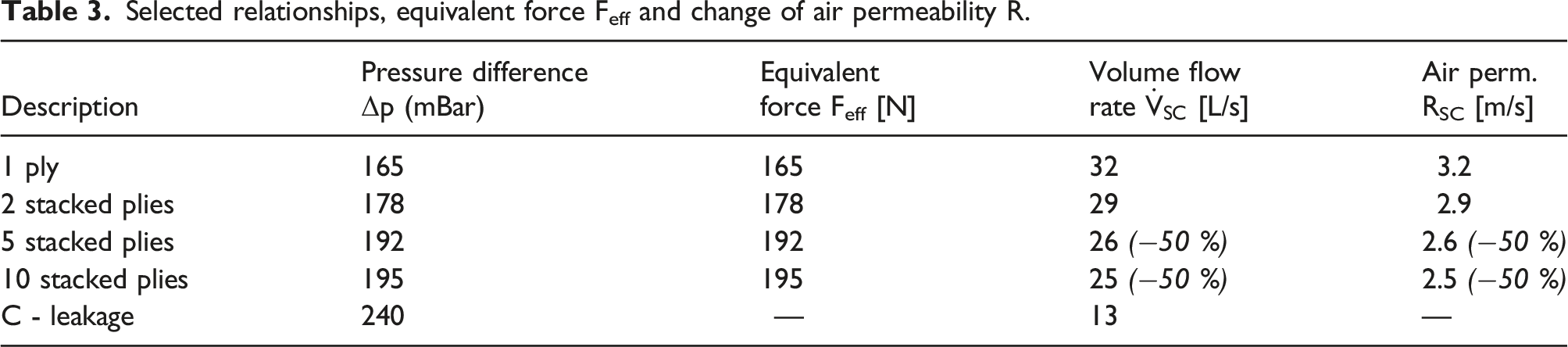
Empirical observations indicate that the directional air flow coming from the holes (flow maxima) is distributed or homogenised over the entire sample area as the number of plies increases. From only two stacked plies, the air flow is spread over the entire surface. The porous properties of the plies due to the layered yarn construction with orientations in +45°/90°/−45°/0° and the resulting alleys with high flowability as well as the flow all around the yarns and between the filaments could cause this (inter-bundle flow and intra-bundle flow).52,53 The calculation based on Aeff is therefore a good approach.
Finally, it can be determined that under the conditions C (closed support area – holes are air-tightly closed) a leakage between (6) and (4) (cf. Figure 3) occurs, which includes 13 L/s at Δp = 240 mBar. This means that the values in Table 3 contain a proportion of leakage flow that cannot yet be quantified. It is assumed that the values
A further result from these measurements is obtained by comparing the volume flow rate delivered by the hot air tools
Heating behaviour of the plies observed with thermography
The two cases “with pressure” and “without pressure” with two different process times tP are examined. In each case, the stack consists of five plies with a total thickness of sT = 5 × 0.75 mm = 3.75 mm. The case “with pressure” examines heating of the stack with the compressor switched on, which according to Table 3 causes a pressure of Δp = 192 mBar and a volume flow through the stack of
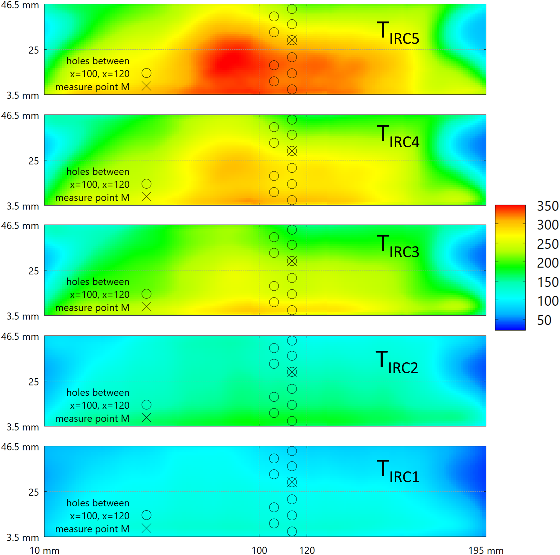
For the thermography measurement, two process times tP = 2.5 s (Figure 11) and tP = 5.0 s (Figure 12) were applied. The figures show the calibrated temperature fields Imcal of the surface of ply 1 (TIRC1 – coldest ply at the bottom) to ply 5 (TIRC5 – hottest ply at the top, with direct contact to the hot air in the housing). The binder is always on the bottom side of each ply, so that e.g. the surface temperature TIRC1 of ply 1 describes the binder temperature of ply 2 and so on. Due to the small amounts of binder compared to the textile mass, it is assumed in this work that the binder has at least the determined surface temperature of the ply or is even hotter. Temperature fields in °C of the plies 1–5, Δp = 192 mBar, tP = 2.5 s. Temperature field in °C of the plies 1–5 Δp = 192 mBar, tP = 5.0 s.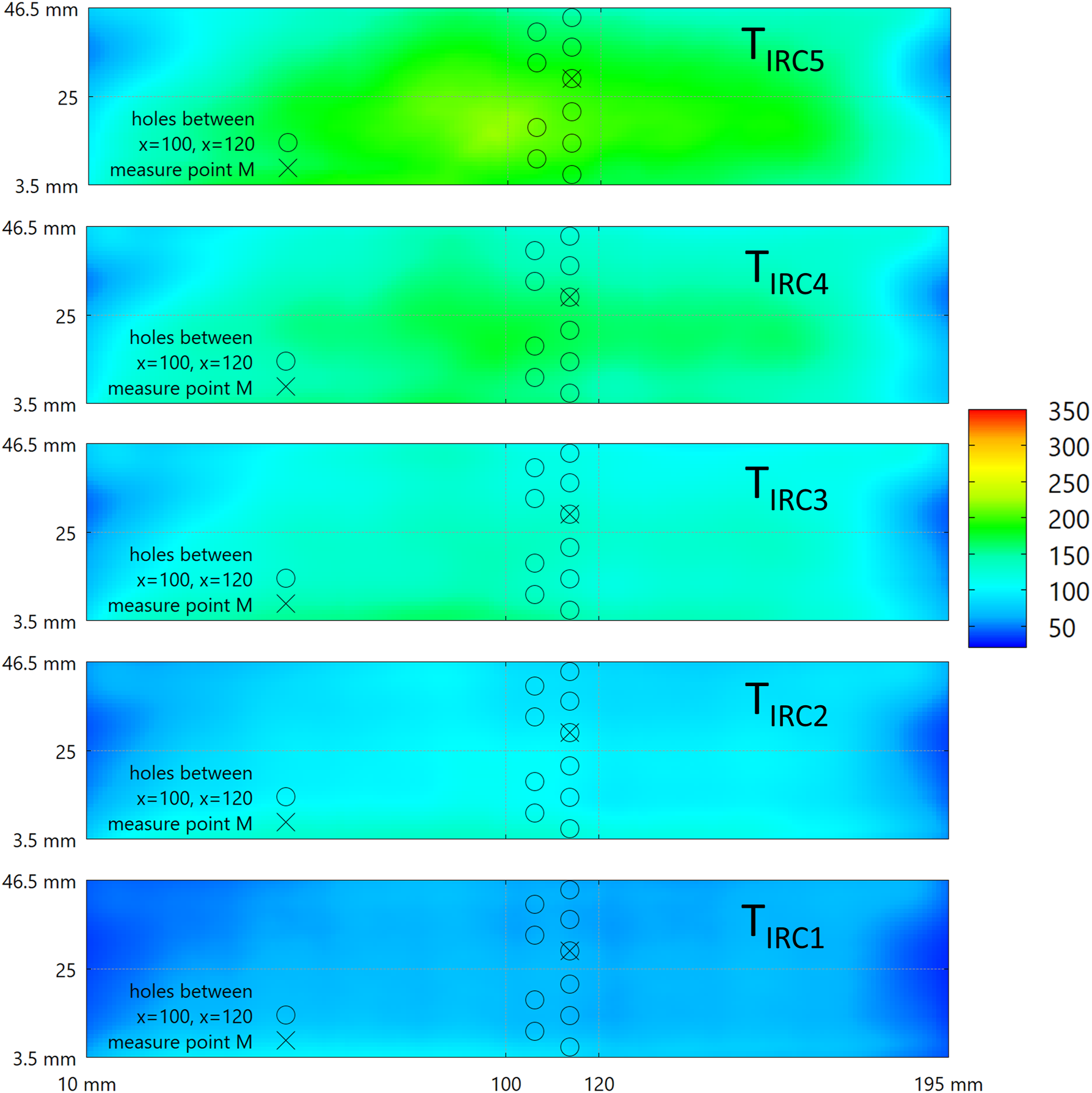
A direct determination of the binder temperature or a differentiation from the textile temperature is – as was determined – not possible with the thermographic measurement setup used. In the figures, tongue-shaped cold areas are clearly visible on the left and right hand sides. At these points, cold air from outside the housing is drawn through the stack. Depending on the plies, the temperatures in the middle area are approximately constant. The bottom ply 1 and thus the binder temperature of ply 2 reaches approx. 50°C after 2.5 s, the top ply reaches approx. 200°C. According to the definition in this work, at least 90°C are necessary to melt the binder sufficiently (activation temperature).
According to Figure 12, the surface temperature of the bottom ply TIRC1 is approx. 100°C after a heating time of 5.0 s and exceeds the necessary activation temperature of the binder, leading to the conclusion that the through-air thermobonding process can activate the binder in the entire stack within 5.0 s. In colder areas, the temperature of the textile and probably of the binder is above 60°C.
Coutandin et al. 54 provides extensive physical characterisations of the binder, such as its viscosity. Accordingly, the binder has a glass transition temperature in the range of 50 to 57°C. Above this temperature, the transition from a solid to a liquid-viscous state occurs. This is associated with a significant decrease in dynamic viscosity from η(70°C) = 1.35⋅107 Pa⋅s, η(100°C) = 3.30⋅103 Pa⋅s to η(150°C) = 0.127 × 10² Pa⋅s. The publication also contains information of the binder decomposition as a function of temperature based on a thermo-gravimetric analysis. The authors conclude that the binder remains completely stable up to a temperature of 270°C. From this temperature up to approx. 480°C, the chemical decomposition or evaporation of the material occurs with a mass reduction of 88 %. The stable temperature range up to 270°C should therefore be used to soften the binder.
As can be clearly seen in Figure 12, there are areas with a high temperature of approx. 350°C in ply 5 (TIRC5). The hot air tools that deliver a temperature TIN of approx. 360°C cause these high temperatures. Figure 6 shows the inlet position (2). The flow caused by the pressure difference draws some of the hot air directly from the inlet over the distances into the textile, which explains the high temperatures. However, the binder is present on the bottom of ply 5 and thus very close to the temperature of TIRC4. TIRC4 is approx. 250°C, which is just below the decomposition temperature of the binder.
However, the high temperatures of TIRC5 can initiate the melting and decomposition of the stitching threads. However, this was not observed within the process time of 5.0 s. The high temperatures are most likely only present on the surface and do not affect the entire stitching thread. With process times longer than 7.5 s, a dissolution of the stitching threads is observed.
Further precautions should be taken to improve the stability of the process against excessive local temperatures of the binder and stitch threads. A largely homogeneous temperature field must be ensured. This can be achieved by supplying the same amount of hot air as is extracted. Furthermore, constructive arrangements are necessary to create a very homogeneous temperature field in the housing. This can be achieved, for example, by improving the seal against the cold outside air. In particular, it is essential to provide thoroughly mixed air at a constant temperature or to intermix the hot air in the housing (e.g. with a fan). The inlet temperature of the hot air should be set to a value below the stability limit of the binder. However, it can be assumed that the process time will significantly increase if the temperature is lower than in the experimental setup.
Heating behaviour observed with thermography and thermocouples
The two cases “with pressure” and “without pressure” within a process times of tP = 10 s are examined. Figure 13 shows the graphs of the thermocouple measurements TTE1 to TTE4 at the measuring point M as well as the temperatures of the thermography TIR1 to TIR5 taken from Figures 11 and 12 at point M and in case of “with pressure”. Graphs of thermocouple measurements and points of thermography at measuring point M in case “with pressure”.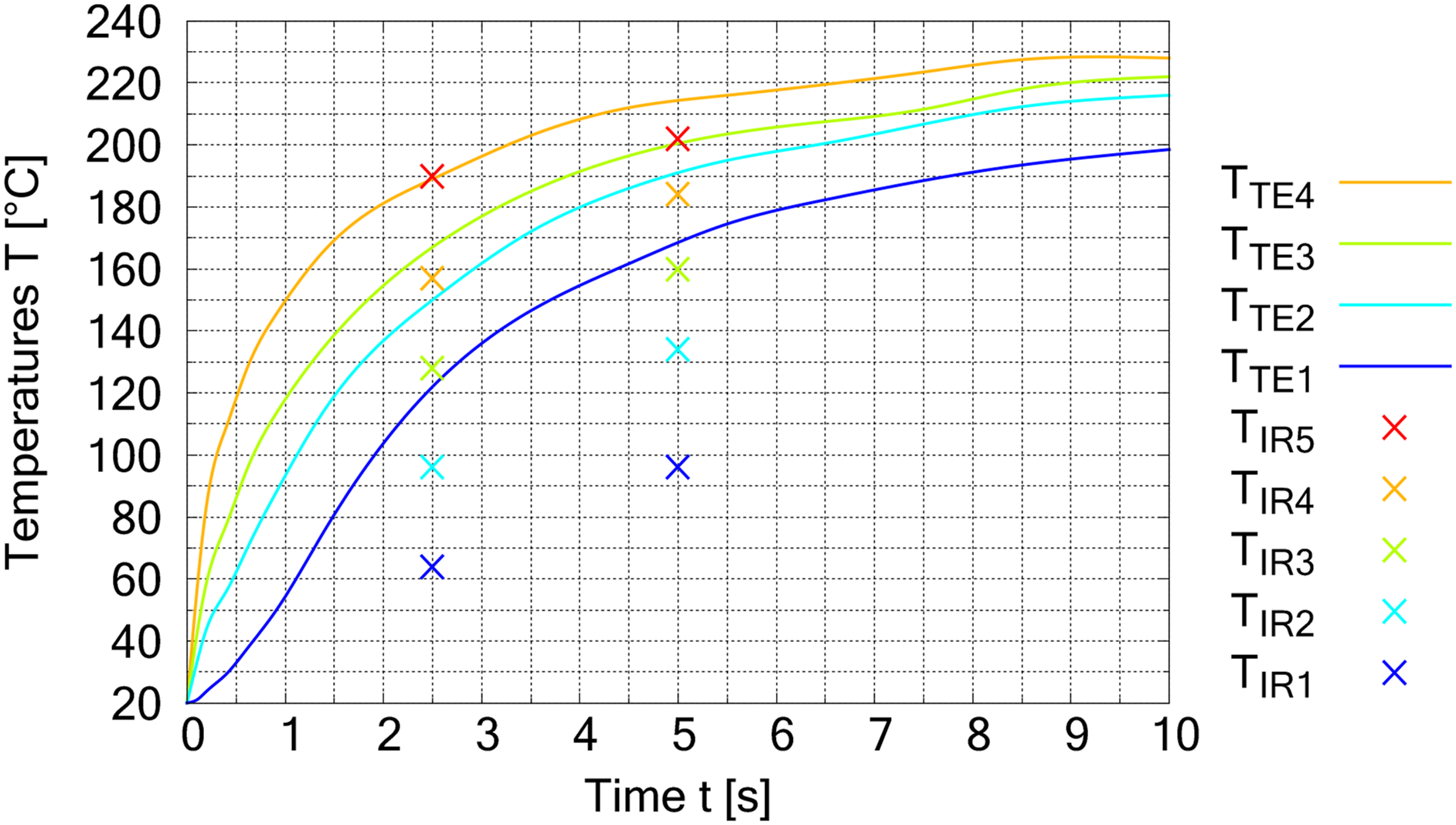
As can be clearly seen in Figure 13, the hot air temperature TTE4 at time slightly larger than t = 0 s is approx. 20°C–40°C. This means that the hot air (initially approx. 250°C) was very strongly cooled as it flowed through the overlying fabric (ply 5, cf. Figure 6) and transferred the heat to ply 5. The temperatures TTE4 to TTE2 rise very quickly with a rapid gradient, while the temperature of TTE1 rises more slowly. There is a temperature difference of approx. 20–40 K between the temperature curves across the entire profile. The temperature difference between the middle graphs and thus in the middle of the stack is slightly smaller. From the time t = 5 s, the temperatures rise slowly and asymptotically towards the maximum of 250°C. The progression is an indication that heat is still being transferred to the fabric, whereby it is clear that TTE1 still needs a long time to reach the maximum.
Furthermore, it is obvious that the thermocouples TTE1 to TTE4 measure a significantly higher temperature than was measured with thermography (TIR1 to TIR5). This leads to the assumption that the thermocouples indicate the temperatures of the hot air and not the temperatures of the fabric. Another important finding associated with this result is that hot air (fluid) and textile (solid) appear to be in thermal non-equilibrium.
The results of the thermocouples are available as a function of time, but indicating the hot air temperature. The thermography results, on the other hand, are only available at two points in time, but show the temperature of the fabrics. This study is particularly interested in the time-related heating behaviour of the textile and therefore also the time-related heating behaviour of the binder.
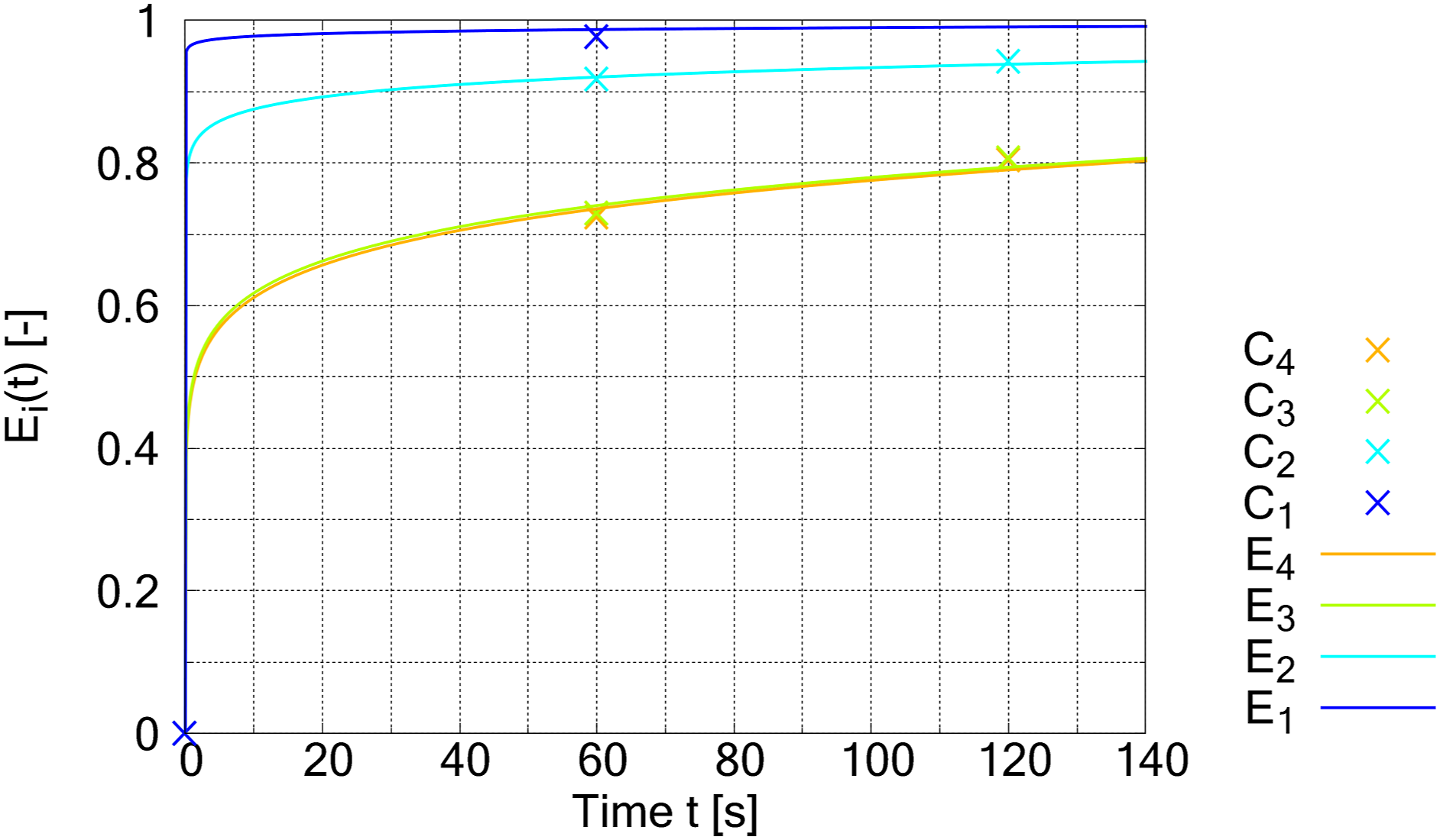
In order to determine the heating behaviour over time, the relation Ci between TTEi and TIRi, plies i = 1.4 with starting temperature T0 = 20°C and t2 = 2.5, t3 = 5.0 s is determined with equation (8). The Ci thus describe the ratio between measured temperatures in reference to 0°C. However, the ratio is only present at two points per ply.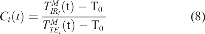

Figure 14 shows the plot of Ei(t) according to equation (9). The function Ei describes the ratio of the two temperature measurements over time. Calculated functions Ei with i = 1.4 in case “with pressure”.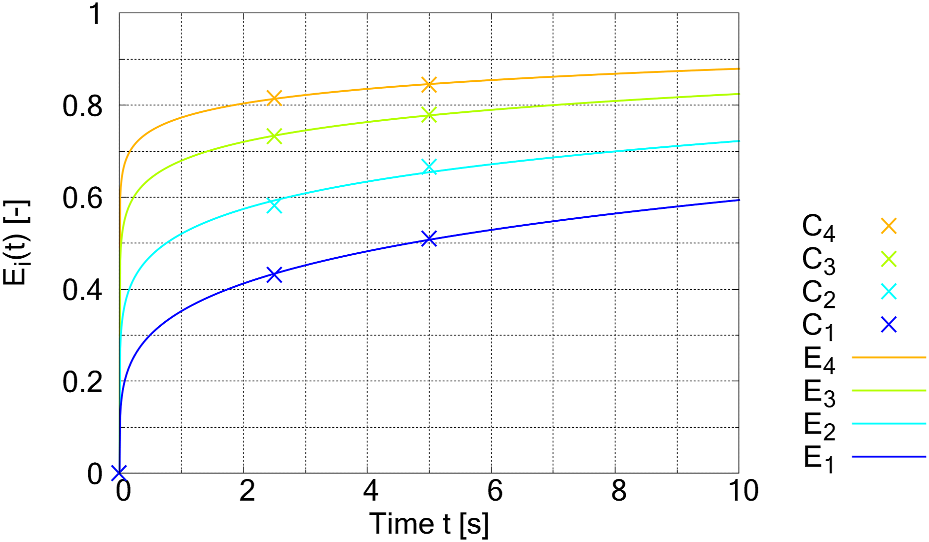
By applying equation (10), the heating behaviour of the surface of the plies and thus the melting behaviour of the binder over time is approximated.
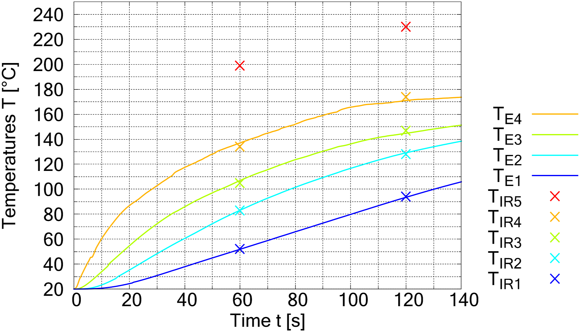
Figure 15 presents the result by applying equation (10). As can be seen the graphs TE1 to TE4 agree very well with the TIR1 to TIR4 at the points tP = 2.5 s and tP = 5.0 s, so that the approach is suitable. The surface temperature of the bottom ply (TE1) resp. the binder reaches the defined activation temperature of 90°C after approx. 4.5 s, the top ply (TE4) already after 0.5 s. The diagrams TE4-TE1 show a high heating rate within the first 2.5 s, which decreases from an initial 56 to 18 K/s as the number of plies through which the hot air flows increases. After these first 2.5 s, the graphs show a degressive curve. The hot air continues to transfer heat to the fabric, but the heating behaviour is presumably dampened by the smaller temperature difference between the hot air and the surface temperature of the fabric and by the heat conduction in the fibres. The fibres presumably become increasingly warmer towards the inside. Between the different plies there is a noticeable temperature difference of approx. 30 K. Based on the progressions, it can be deduced that with a larger number of plies (nP > 5), the time to reach the activation temperature of the binder increases significantly. In order to be able to process a number of plies of up to nP = 10 at a similarly fast heating rate, further methods are required. Heating behaviour of the sample’s surfaces and thus the presumed melting behaviour of the binder in case “with pressure”.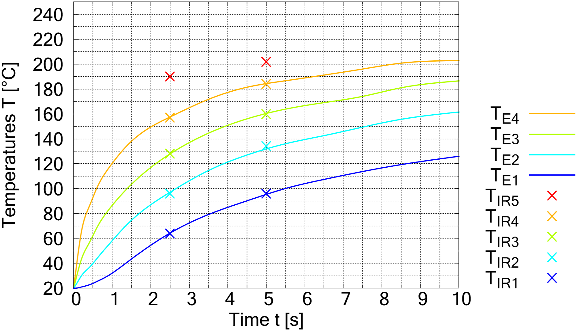
These envisage, for instance, changing the input temperature of the hot air TIN in stages during the process. This provides the opportunity for hot air at a lower temperature as the top plies to flow through the top plies, so that heat is transferred from the fabric to the hot air. The heated air can in turn transfer heat to the bottom fabric plies. This also has the advantage that the top plies ideally hold the heat required to melt the binder and the bottom plies reach the activation temperature distinctly faster.
The case “without pressure” examines heating the textile stack with the compressor switched off. Consequently, heating the textile stack only occurs on the top surface and on the sides by nearly free convection. The temperature spread in the intermediate plies up to the bottom ply is mainly due to heat conduction in connection with the air in the fabric resp. the porosity.
The diagram in Figure 16 shows the behaviour up to a process time of tP = 140 s, where the IRC measurements were conducted at times tP = 60 s and tP = 120 s. It can be seen that the temperature measurements TIRi compared to TTEi deviate from each other, but significantly less than in the case “with pressure”. The bottom ply even shows identical values, which allows the conclusion that a continuous heat exchange occurs between the fabric, air and thermocouple due to the heat conduction of the fibres and the slow heat convection of the air in the textile. This can also be seen in Figure 17, as the graphs for E1 and E2 run close to 1. Figure 18 shows the heating behaviour after exponentiation with equations (8) to (10). The exponentiation approach Ei(t) provides a largely reliable approximation in this case. The surface temperature of the bottom ply (1) resp. the binder reaches the defined activation temperature of 90°C after approx. 120 s, the top ply (4) after 20 s. In case “without pressure” the heating up time is approx. 26 (1) to 40 (4) times longer compared to the pressurised setup. Graphs related to Figure 13 but in case “without pressure”. Calculated functions Ei with i = 1..4 in case “without pressure”. Graphs related to Figure 15 but in case “without pressure”.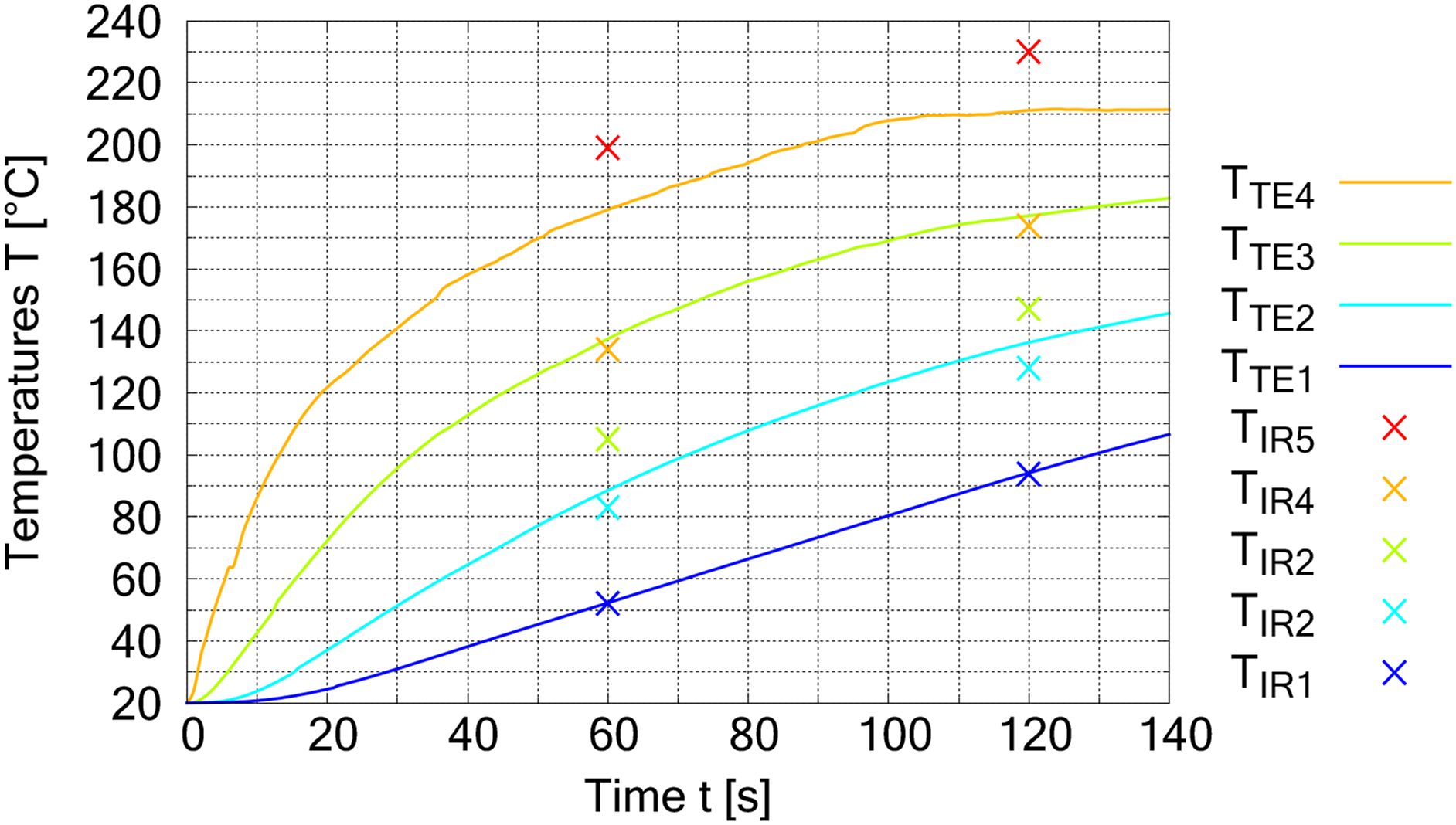
Resulting bending stiffness and comparison
Figures 19, 21 and 22 show the results of the bending stiffness measurements for the three cases “unprocessed”, “without pressure” and “with pressure”. The measurements show significantly higher bending stiffness depending on the position of the 0°-threads “from top” or “from bottom”. According to theoretical considerations, the values “from top” should be slightly higher than the values “from bottom”, as the 0° position is loaded in tension in the top position and in compression in the bottom position. Some measurements show this behaviour, but the standard deviation does not allow a reliable differentiation. The evaluation is therefore based on the values “both”, which do not take any differentiation into account. Resulting bending stiffness in case “unprocessed”.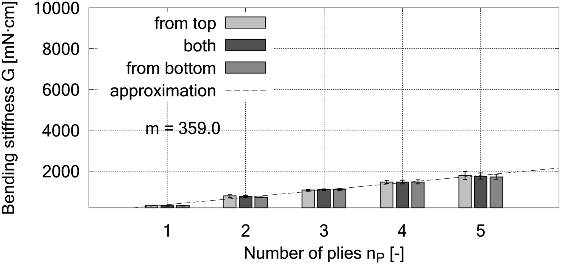
Beyond that, it can be seen in Figure 19 that the stack of unprocessed plies shows a linear increase in bending stiffness with the number nP of stacked plies. The behaviour corresponds to equation (6), where the mass increases with each ply added, but the overhang length l0 during the measurements remains the same.
Another explanation results from the moment of inertia of a rectangle with the height t (thickness of the fabric according to equation (11) and defined in the z-axis), which is loaded along the x-axis and bending around the y-axis (w denotes the width and top index up means unprocessed). Since in a stacked arrangement, as in the present case, the centres of gravity of each ply lie on one line. Therefore Cantilever testing of 5 stacked plies in case “unprocessed”.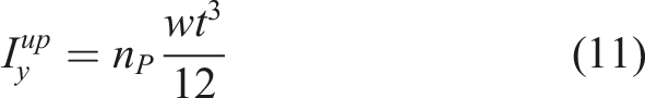
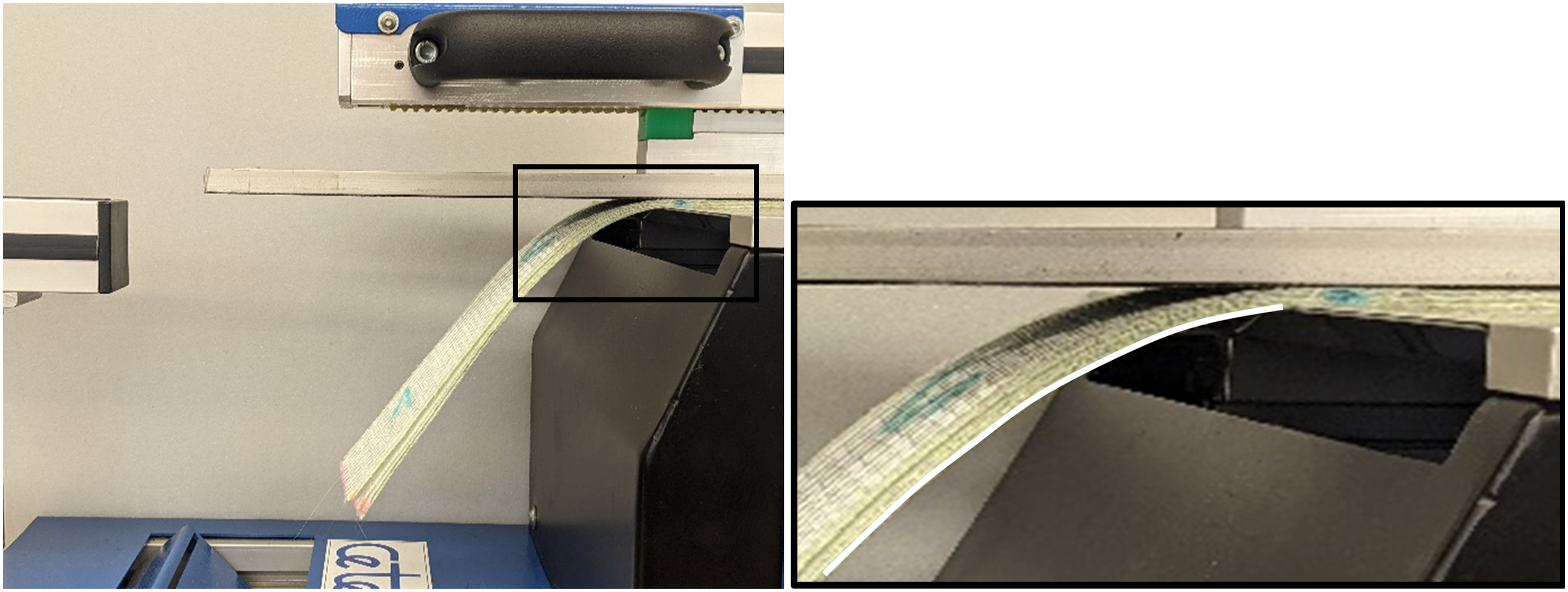
Figure 21 shows the behaviour of the stacked plies after processing by free convection without pressure and a process times of tP = 120 s. The activated binder bonds the individual plies together, which leads to approximately a doubling of the stiffness compared to unprocessed stack (Figure 19). Shear is prevented as a result of the ply bonding. According to the approach for determining the area moment of inertia, however, it is now assumed that the plies are bonded together to form a solid textile body. It is also assumed that the adhesive bond can absorb the shear forces between the plies. This leads to equation (12) with index p meaning processed. The relationship shows an increase of Resulting bending stiffness in case “without pressure”.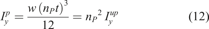
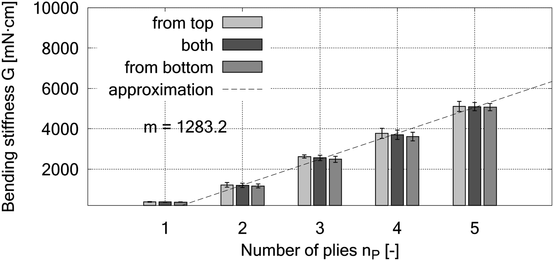
Figure 22 shows the achievable high bending stiffness using the method developed and shown in this work (case “with pressure”). The stack is heated within a process time of tP = 5.0 s (cf. Figure 12) by means of forced convection. With further exposure to air at room temperature, rapid cooling takes place by forced convection. During cooling the equivalent force Feff = 192 N or the surface force qeff = 192⋅10−4 MPa also act on the stack according to Table 3. The graphs show nearly a doubling of the bending stiffness compared to the case “without pressure” (Figure 21), while still following a linear characteristic. There is a perfect linear relationship with a steep gradient m. Resulting bending stiffness in case “with pressure”.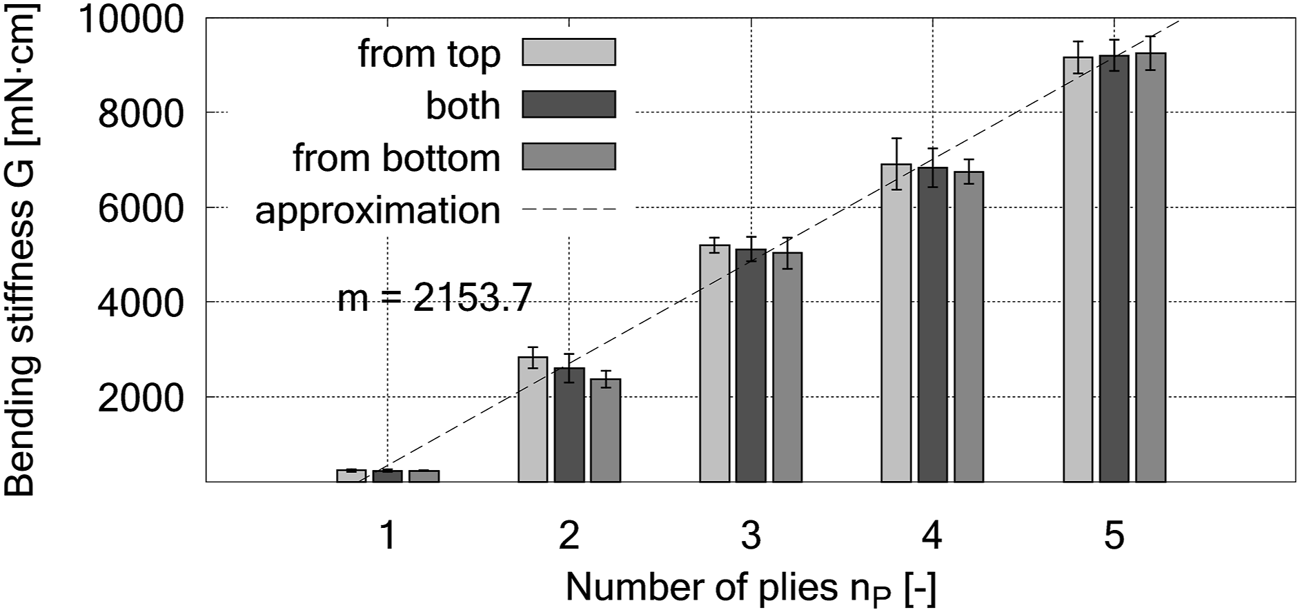
The significant increase in bending stiffness is due to the compaction and the associated contact resp. contact area between the plies. The applied binder particles are small in size, while the fabric FGE109 has a structured and uneven surface topology with hills and valleys (cf. Section Materials). The adhesive bond can only be formed well if the topological differences are equalised by compression while the binder returns to the solid phase. Assuming that the adhesive strength of the binder does not change, it can be concluded that the adhesive area has almost doubled as a result of the compression compared to the case “without pressure”.
Figure 23 shows in comparison to Figure 20 one representative example of the bending test using nP = 5 plies. A clear failure of the stack at the clamping point can be seen, which leads to the results of the bonded cases according to the graphs in Figures 21 and 22 with the number of plies nP = 2 to 5. During the test, the bonded stacks remain largely flat resp. without visible deflection and failure with overhang length l0 (cf. Equation (6) due to buckling. The highest bending moment occurs at the point of failure. The buckling can be caused either by the adhesive bond being too weak at this point or by the compressive load on the fibres at the bottom of the stack and the associated anisotropic Young’s modulus. In combination with the failure of the adhesive bond, the fibres can also pull out of the fabric, which can also contribute to the failure. Cantilever testing of 5 stacked plies in case “processed”.
Based on these results and correlations with the area moment of inertia, it is assumed that the cantilever method for determining the bending stiffness of textiles according to DIN 53362 50 and ASTM D1388 51 for a stiff bond of individual plies describes the failure. A linear relationship with increasing number of plies was proven. Whether the measured values correspond to the actual bending stiffness as the product of the Young’s modulus E and the moment of inertia I of the stacked textile fabric cannot be validated with the results. It is supposed that the theoretical relationships in mechanics are valid for a solid body such as a FRP, but that the definitions must be corrected for textile fabrics such as preforms. It is also known from the literature57–59 that the Canitilever method can achieve high deviations from the actual value of the bending stiffness depending on the test material.
In general, the curvatures of fabrics are non-linear, so different methods can generate different values, even for the same materials. 60 By testing the bending stiffness, however, a method was adopted that conclusively demonstrates the influence of successful binder activation by free and forced convection and compaction of the textile stack during cooling. Further evidence can be provided by characterisation using two- or three-point bending test, e.g., a method according to Schlenker, 61 and shear tensile test, 62 whereby the latter can quantitatively determine the adhesion shear force for mechanical calculations e.g. as a function of the compaction, binder quantity and, in particular, different activation temperatures resp. heating times. Another method that is commonly used e.g. for adhesive bonds of textile plies 26 is to determine the peel properties between flexible parts using a T-peel test in accordance with ISO 11339. 63 The standard is especially useful for comparative quality checks in identical situations.
In conclusion, while the observed failure provides valuable insights into the mechanical behaviour of bonded textile stacks, further refinement of testing methodologies and theoretical works e.g., Lahey at al. 64 may be necessary to accurately characterize the bending stiffness of such complex and layered structures. This acknowledgement of testing limitations opens paths for future research aimed at enhancing the precision of mechanical property assessments in textile preforms.
The comparison with nP = 1 shows a significantly larger bending stiffness G of 374 ± 18 mN⋅cm (“without pressure”, Figure 22) and 445 ± 22 mN⋅cm (“with pressure”, Figure 21) compared to 316 ± 20 mN⋅cm (“unprocessed”, Figure 19). The binder probably infiltrates into the spaces between the fibres due to capillary forces, which causes the stiffening. After cooling, this results in a fixation of filaments or yarns to each other (intra-laminar fixation). 65 Compared to the bonding of the plies (inter-laminar fixation), 65 however, the achievable stiffening by intra-laminar fixation is low and probably only achievable with significantly larger quantities of binder per area.
Preforms can be given a high degree of inherent stability by means of inter-laminar fixation in order to withstand bending and shear forces until further processing.
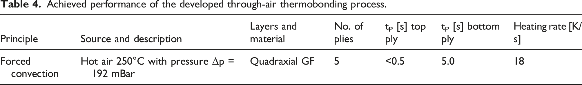
Achieved performance and further advantages of the process
Achieved performance of the developed through-air thermobonding process.
A significant advantage of the process is that the heat transfer medium is transported to the heat transfer location by the flow (Advection). The compression allows the fabric plies to bond particularly well and increases the preform stiffness, which can be achieved without the need for further mechanical entities. All that is needed is a pressurised contact surface of any three-dimensional shape and surrounding hot air.
Based on the short process times, it can be safely assumed that only the surface of the textile will take on the temperatures shown. Due to the slower heat conduction in the material in comparison, only a small amount of heat is transferred from the air to the textile. This is in contrast to heat transfer processes that transfer energy through pure heat conduction as much more mass of the textile is heated. This results in ecological and economic advantages as energy consumption and costs can be significantly reduced. A special feature is that the process is suitable for the heating and the cooling phase. A technical device for switching between the provision of hot air for heating or cold air for cooling enables binder activation and curing to be carried out in a single, fast working process. Further potential energy savings arise from the fact that the aspirated hot air is fed back into the process so that a substantial proportion of the energy can be recuperated. Possibilities for vary temperatures in stages can also be taken into account so that the heating behaviour of the fabrics can be purposefully controlled.
Conclusions and outlook
The study presented here focuses on the development and characterisation of an advanced through-air thermobonding process for the production of textile preforms by hot air. The temperature distribution within the stacked samples was analysed, and variations were found that can be attributed to the properties of the measurement systems used.
The study first evaluated the properties and air permeability of the entire flow system and demonstrated its compatibility with different numbers of stacked plies. The results showed that effective bonding is possible even with 10 plies, which emphasises the versatility of the process. With regard to the number of plies, the study shows that the through-air system has only few limitations as long as sufficient air permeability or porosity is guaranteed.
Thermographic and thermocouple analyses provided information on the heating behaviour of the fabric plies. Despite the non-linearity of thermography due to the temperature-dependent emissivity, calibration methods were used to enable accurate temperature determination. In particular, both temperature measurement methods show deviations from each other. Thermocouples reveal the temperature of the hot air in the fabric plies, especially during short process times. In order to be able to draw conclusions about the temperature of the fabric over time, a mathematical approach relating thermocouple and thermographic measurements was developed. The approach appears to be suitable, but requires the methodology described.
The thermobonding process demonstrated rapid binder activation within 5 s, which is a remarkable reduction in activation times compared to existing methods. However, precautions are needed to avoid high local temperatures that could affect the stability of the binder and the stitching yarns. This can also be accomplished by gradually modulating the inlet temperature of the hot air, which also has the advantage of accelerating the heating behaviour of the bottom plies.
In addition, measurements of bending stiffness have shown that the proposed thermobonding method provides a significant improvement, especially compared to an unpressurised method. The preforms can be given a high degree of inherent stability through interlaminar fixation to withstand bending and shear forces until further processing. While the observed failure provides valuable insight into the mechanical behaviour of such stacked and bonded structures, further refinement of testing methods and theoretical work may be required to characterise the bending stiffness accurately.
The study highlights the potential for energy savings, the efficient activation and curing of the binder in a single process and the adaptability of the through-air process for various textile preform geometries. In the current work, the process is used to fix profiled preforms, e.g., with a closed rectangular shape or open hat shape, in a continuous process shortly after forming. The through-air process can also be used for forming and fixing processes using stamps.
Based on the temperature curves in the individual plies, further work will concentrate on deriving the local and probably very temperature difference dependent heat transfer coefficient or the number of transfer units (NTU) and on simulation-based investigations such as flow simulations with heat transfer. When modelling the process, the thermal non-equilibrium between fabric (porous medium) and hot air (fluid) as well as the heat conduction within the fibres should be taken into account in order to describe the process as necessary. Important parameters such as the energy absorption of the plies can already be determined from the temperature curves visualised. An open research question is the temperatures of the binder in the individual plies. The use of simulation-based methods appears to be suitable for indirectly determining the temperatures of the binder. Further investigations to determine optimum process parameters that help to heat the binder very quickly but minimise the heating of the textile are of great interest.
Footnotes
Declaration of conflicting interests
The author(s) declared no potential conflicts of interest with respect to the research, authorship, and/or publication of this article.
Funding
The author(s) disclosed receipt of the following financial support for the research, authorship, and/or publication of this article: This work was supported by the AiF Arbeitsgemeinschaft industrieller Forschungsvereinigungen „Otto von Guericke“ e.V. (18404 BR).
Data Availability Statement
Data available on request.