
Abstract
The study aims to develop a novel method of weaving multiaxis preform on conventional weaving machines and analyse impact tolerance of the ensuing composites along with development of finite element analysis model. An extra set of 200 tex carbon fibres, referred as bias fibres, were integrated into carbon fibre plain woven fabric during the weaving stage on a conventional closed reed weaving machine. This was achieved by partial carbon fibre weft insertion at regular intervals from both edges of the fabric. The multiaxis preform was used as ply on top of plain woven carbon fabric plies, each of 160 g per square meter aerial density. The carbon fibre composites were manufactured by infusing bisphenol F epoxy resin as a matrix and 4 plies of carbon fabric by hand layup method. The composites were subjected to low-velocity impact loading at 0.4 m height of 5.12 kg impactor, and force-time history was recorded by the piezoelectric transducer. A comparison of impact loading results showed that the multiaxis woven composites increase impact strength by 18.3% due to the reinforcement of bias fibre. Based on the test results, a finite element analysis model was developed in Ansys v.19 to simulate the stress distribution during impact loading of the multiaxis woven composites.
Introduction
In the past two decades, development in multiaxis woven composites has been significant and they are slowly getting integrated in the composite industry. In aerospace applications like wing stiffeners where composites are desired to bear shear loads, fibre orientation in a direction other than warp and weft is a requirement. Such requirements have led researchers to develop multiaxis woven fabrics where an extra set of fibres, apart from warp and weft, are incorporated at a bias angle during the weaving process. These are referred to as bias fibres, and the core challenge to integrate them in the fabric is their position and indexing during weaving process.
Various research attempts have been established to incorporate bias fibres in conventional and 3D weaving processes. 3D weaving is a method of manufacturing textile preforms where the fibres are stacked in multiple layers during or prior to the weaving stage, to manufacture a preform of desired thickness or shape, devoid of distinct layers.1–3 Anahara and Yasui 4 developed a multiaxis 3D weaving mechanism where warp fibres are staggered vertically and, bias fibres are indexed by means of a screw, the weft is inserted by rapier and finally bound by Z fibres, which are inserted vertically by a needle. Bilisik and Mohamed 5 developed a multiaxial 3D weaving machine where tubes are used as guides for warp fibres and to index the bias fibres. The machine is devoid of conventional reed and beat-up action is carried by an element which inserts Z fibre. Ruzand 6 developed a multiaxis 3D weaving machine based on the lappet weaving principle. On a conventional weaving machine special needle, which operates between reed and cloth fell, indexes the bias fibres. Uchida et al. 7 developed a multiaxis weaving machine where bias fibres are passed over a rotating chain on a horizontal axis. This chain indexes fibre one unit during each weaving cycle, and the weft is inserted by rapiers in a permanent open shed and locked by Z fibres. Fibres are oriented in five directions, that is +bias, −bias, warp, weft and Z fibres. Mood 8 modified the conventional reed into a split reed and combined with a jacquard head to manufacture multiaxis woven fabrics. Nayfeh 9 developed a multiaxis weaving machine based on the sliding tube principle for producing 3D woven fabric consisting of warp, weft, and ± bias yarns. Bias yarns pass through tubes mounted on grooves in a block, while the warp is passed through the space between adjacent blocks, and a shuttle is used for weft insertion. Bryn et al. 10 developed a multiaxis four-layer fabric with ±bias, warp, and weft yarn sets based on the multilayer narrow weaving principle. Various cross sections can be woven, and biased yarns are continuously traversed for plain weave structure via an individual hook. An open reed rapier weaving machine manufactured by Lindauer Dornier GmbH uses an extra set of linear actuators mounted on heald shaft to shift bias yarns in the direction of weft in addition to up and down motion of the heald shaft. 11 In conjugation with an open reed, this machine can integrate bias fibres at customised angles to warp. Donald W. Schmanski 12 designed a weaving machine which adjusts the fabric take-up roller to orient weft at bias angle. In this system, the weft can be oriented in a gradual change of angle from 90 to 0°. Bruyere et al. 13 developed a weaving machine, which orients warp and weft fibres at 45° and then weaves them into the fabric. However, this technique does not allow to integrate fibres in multiple axes. Wang et.al 14 have designed multiaxis weaving setup based on spindles mounted on perforated board. This weaving machine can manufacture multiaxis 3D woven preforms upto thickness of 85 mm. Labanieh et.al 15 developed multiaxis weaving machine which can integrate bias fibres in sandwich layers of 3D woven preform. Kimbara et al. 16 developed multiaxis weaving loom by inserting rigid rods in triaxial configuration.
In the majority of multiaxis weaving machines and techniques, the alignment of bias fibre is in warp direction.17,18 In such a setup, the reed and heald wires pose as an obstacle while attempting to index the bias fibres during the weaving process on conventional weaving machines. Thus, complex modifications in the weaving machine are required to incorporate fibres in multiple axes, such as designing rotating creels, modifying the shedding and reed setup, etc.
The effect of bias yarn on tensile properties of 3D woven composites have been studied and modelled, which suggests that bias yarn suffer in-plane shear damage and lower the tensile strength of the composites.19–22 To evaluate the effect of fibre orientation in multiple directions on composite properties, one of the feasible method is impact testing of composites, as it shows combined strength of the material in tensile, flexural, compression and shear.23,24 Composite thickness and ply orientation are significant parameters which can influence the resistance to impact. 25 The impact strength directly depends on composite thickness, while ply orientation has a more complex relation. Plies with similar fibre orientation show higher impact strength than those with fibre orientation in multiple angles.26,27
Based on the prior research on multiaxis composites, there exists a research gap for development of new manufacturing method of multiaxial preforms which does not require complex machine modifications. Subsequently, there also exists a research gap on evaluation of multiaxial composite mechanical properties and simulation. Thus, this research work focuses on filling the research gap by developing a novel method of manufacturing multiaxis preforms on a closed reed shuttle weaving machine and evaluating the impact properties of the ensuing composites along with finite element analysis (FEA) model development. The purpose of choosing closed reed weaving machine was to reduce the complexity and cost of the weaving machine by 30% as compared to the existing multiaxial weaving machines. As compared to previous research on the integration of bias fibres in warp direction, a different approach to incorporate bias fibres in the weft direction is described in this work. The carbon fibre multiaxial preforms were woven on a closed reed shuttle weaving machine with a dobby attachment. The bias fibres were incorporated at ±45° angle to warp by additional shuttles, thus avoiding complicated modifications in the weaving machine. This method also allowed flexibility to incorporate fibres at customised angles between 0 and 90°. The composites were manufactured by resin infusion in the multiaxis carbon fabric using the hand layup technique and were subjected to impact loading to study the effect of bias fibres on the transversal properties of the composite. A FEA model was developed in Ansys to simulate the impact response of the multiaxis composites.
Materials and methods
Weaving process
Carbon fibres AS4™ of 200 tex 3K HexTow® supplied by R&G Faserverbundwerkstoffe GmbH® were used to weave multiaxis fabric on 24 heald shaft dobby machine.
3
In this context, bias fibres can be considered as partially inserted weft, which have multiple anchor points along the length of the fabric as shown in Figure 1. These anchor points determine the ±θ bias angle of the overall fabric, and each bias fibre requires an individual shuttle. The shuttles assigned for bias fibre are different from those used for full-width weft insertion, thus forming 2 separate sets. Part of the fabric having warp and weft will be referred as base fabric whereas fibres incorporated at customized angle will be referred as bias fibres. For simplification purpose, the following steps for weave preparations are not explained or showed in detail: 1. Weaving preparation as per the conventional method that is, warp drawing and denting; weave designing, lifting plan etc. 2. Calculating the number of bias fibres required and subsequently assigning the number of shuttles for bias fibre insertion. In the present study, 6 bias fibres were inserted by 6 shuttles (3 bias fibres from each selvedge) to form a uniform distribution over the entire preform area. 3. Assigning the anchor points for the bias fibres based on ±θ angle requirement. 4. Full width weft insertion as per the lifting plan and shed formation. (a) Gripping of bias fibre, (b) indexing of bias fibre in the warp direction, (c) indexing of bias fibre in the weft direction, (d) maintaining orientation of shuttle, (e) repetition of steps (b–d) with the advancement of bias fibre, (f) complete integration of bias fibre across the width.
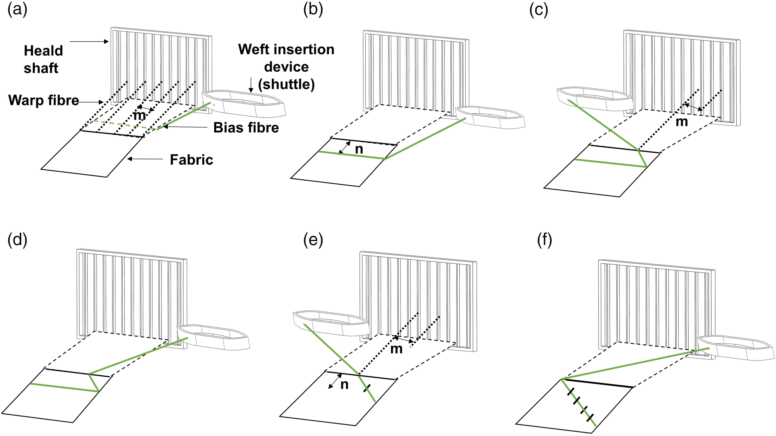
Stepwise description of the bias weaving process is explained from step 1 to step 4 as shown in Figure 1.
In step 1, the shuttle is passed through the full width of the fabric to initially grip the bias fibre as shown in Figure 1(a).
In step 2, the bias fibre insertion is paused until n number of full width weft insertions are completed as shown in Figure 1(b).
In step 3, a single warp thread at m distance from the selvedge, assigned as one of the anchor point, is lifted and the bias fibre weft is inserted as shown in Figure 1(c). This marks as the starting point for indexing of bias fibre, which can be either from the selvedge or from an anchor point interior in the fabric, away from the selvedge. In this step, the former case is demonstrated.
In step 4, the bias fibre shuttle is brought to its initial position without anchoring to any warp, as shown in Figure 1(d). To orient bias fibres at the required angle, it is important that weft insertion should be only in a single direction that is, either right-left or left-right.
Steps 2–4 are repeated and the bias fibres are integrated with multiple anchor point warp, as shown in Figure 1(e) and 1(f). When the bias fibres reach selvedge, reversal of path is achieved by reversing the direction of shuttle insertion, reversing the order of anchor points and repeating steps 2–4. These steps are further applied to multiple shuttles to integrate bias fibres over a maximum surface area of the fabric. Out of multiple shuttles, only one bias fibre shuttle is inserted at a time to avoid anchoring of single-bias fibre at multiple points.
The machine consists of creels to feed warp, 24 heald frames (electronically controlled), a shuttle for weft insertion, multi-beat-up action for firm and compact beat-up, positive take-up for assured weft density and take-up at will for obtaining bias fabrics. The working width of the weaving machine is 400 mm. The multiaxis sample woven was of size 400 mm × 400 mm with 160 g per square meter aerial density.
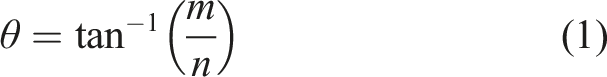
The bias angle θ, as shown in Figure 2(c) can be defined as angular distance between warp and bias fibre. The bias fibre makes this angle by shifting in predetermined distances between warp and weft, respectively. As shown in Figure 2(a) and 2(b), if the distance between warp, assigned for anchoring the bias yarn is m, and bias yarn is anchored at n intervals of inserted weft then the angle θ and float length of the bias fibre l can be calculated by equations (1) and (2), respectively. The values of m and n are 10 mm, respectively. The resultant angle θ is 45° with float length of 14.1 mm. Conceptualisation of bias weaving parameters: (a) distance between anchoring warp fibres m, (b) number of inserted weft fibres n, (c) angle θ between the warp and bias fibre.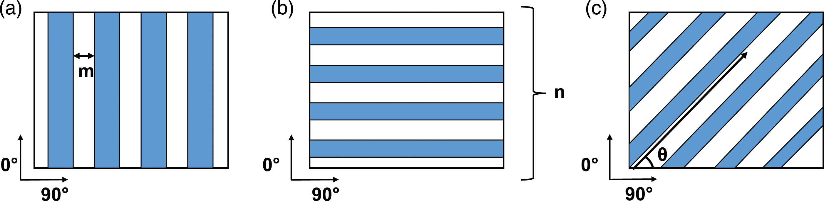

Composite manufacturing
Sample identification and stacking sequence.
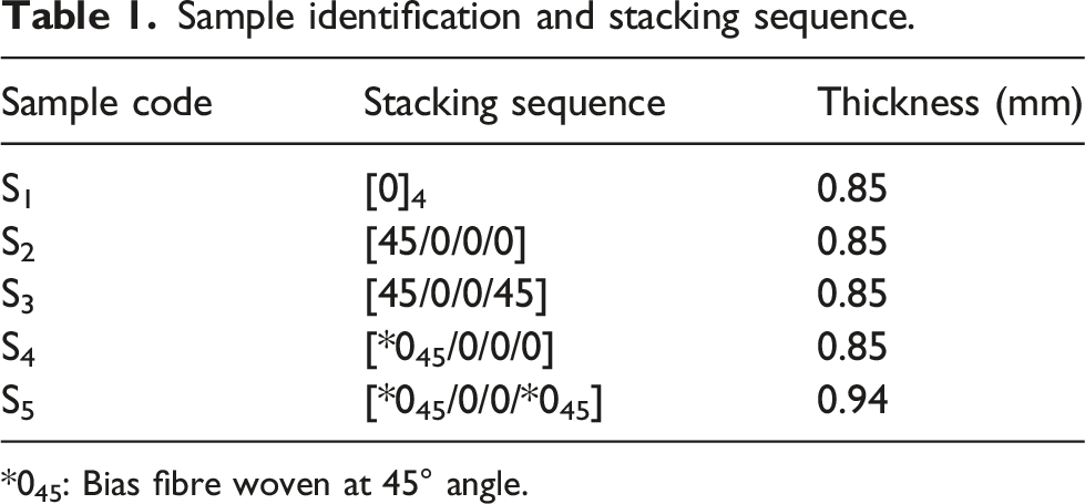
*045: Bias fibre woven at 45° angle.
Impact testing
For determining the effect of bias yarns on out-of-plane properties of the composite, impact testing according to ISO 6603-02 standard was performed on Coesfeld low-velocity impact machine. Five composite samples were fastened with a circular clamp of 40 mm inner diameter. The samples were impacted with a 5.18 kg impactor having 20 mm diameter, with drop height of 0.4 m, amounting to total energy of 20 J. The piezoelectric sensor with a frequency of 1 Mhz was placed near the clamp to measure the impact force acting on the sample. The impact machine registered 3 readings of the force in time interval of 0.001 ms. The impact energy absorbed by the composite was calculated by equations (3) and (4) according to the ISO 6603-02 test standard.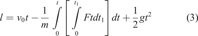
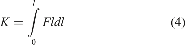
Where l is the deflection in meters, v 0 is the impact velocity, F is force exerted by impactor on specimen measured in Newtons, t is time in seconds, m is mass of the impactor in kilogram, K is energy absorbed by the composite measured in Joules, g is the acceleration due to gravity expressed in meters per second squared.
Finite element analysis of impact loading
To complement the experimental results of impact testing detailed in section 2.3, a FEA model was developed in Ansys v.19 with ACP (Ansys composite pre-post) module and explicit dynamics to simulate the force time history of plain woven, angle ply and multiaxial woven composite subjected to impact loading.
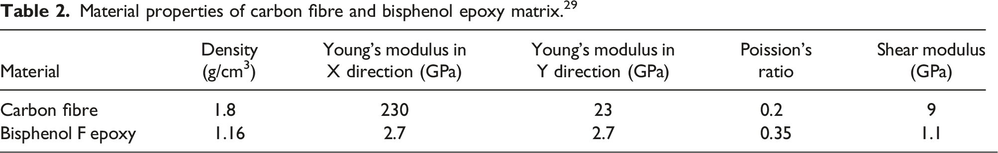
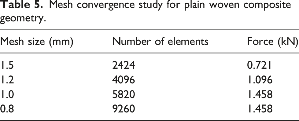
A 0.8 mm mesh with shell elements having 4 nodes were designed as per the actual dimensions of the composite plate in the Design Modeller module and input to ACP pre module as shown in the process flow chart of Figure 3(a). The carbon fibre and bisphenol epoxy material properties detailed in Table 2 were defined in the Engineering Materials module and input to the Material Designer module. This module of Ansys takes the orthotropic properties of carbon fibre and epoxy resin isotropic properties as input, applies it to the plain weave representative volume element as shown in Figure 3(b) and generates composite material properties by applying non periodic boundary conditions, as listed in Table 3 assuming 50% fibre volume content.
28
Process flow of FEA in Ansys, (a) workflow setup, (b) unit cell of plain woven fabric, (c) geometry for S1, S2 and S3, (d) geometry for S4 and S5. Material properties of carbon fibre and bisphenol epoxy matrix.
29
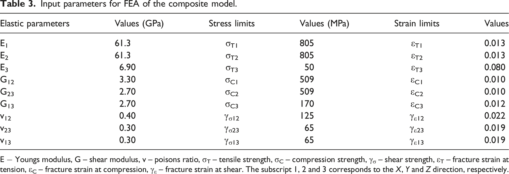
Input parameters for FEA of the composite model. E − Youngs modulus, G – shear modulus, v – poisons ratio, σT – tensile strength, σC – compression strength, γσ – shear strength, εT – fracture strain at tension, εC – fracture strain at compression, γε – fracture strain at shear. The subscript 1, 2 and 3 corresponds to the X, Y and Z direction, respectively.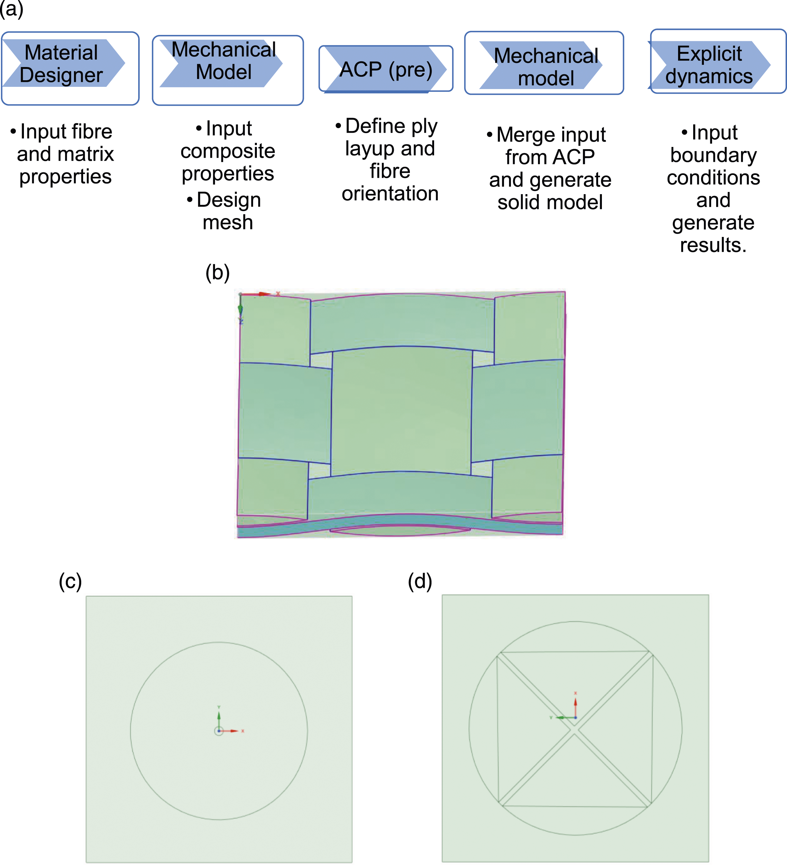
Hashin Failure criteria.
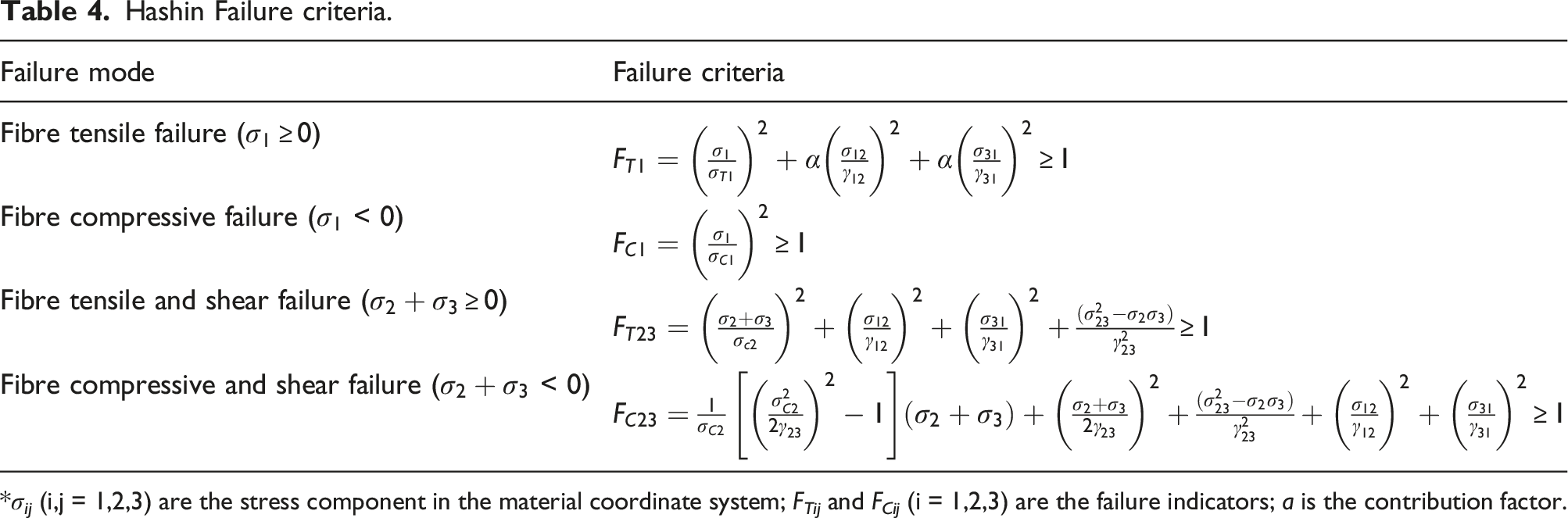
*σ ij (i,j = 1,2,3) are the stress component in the material coordinate system; F Tij and F Cij (i = 1,2,3) are the failure indicators; a is the contribution factor.
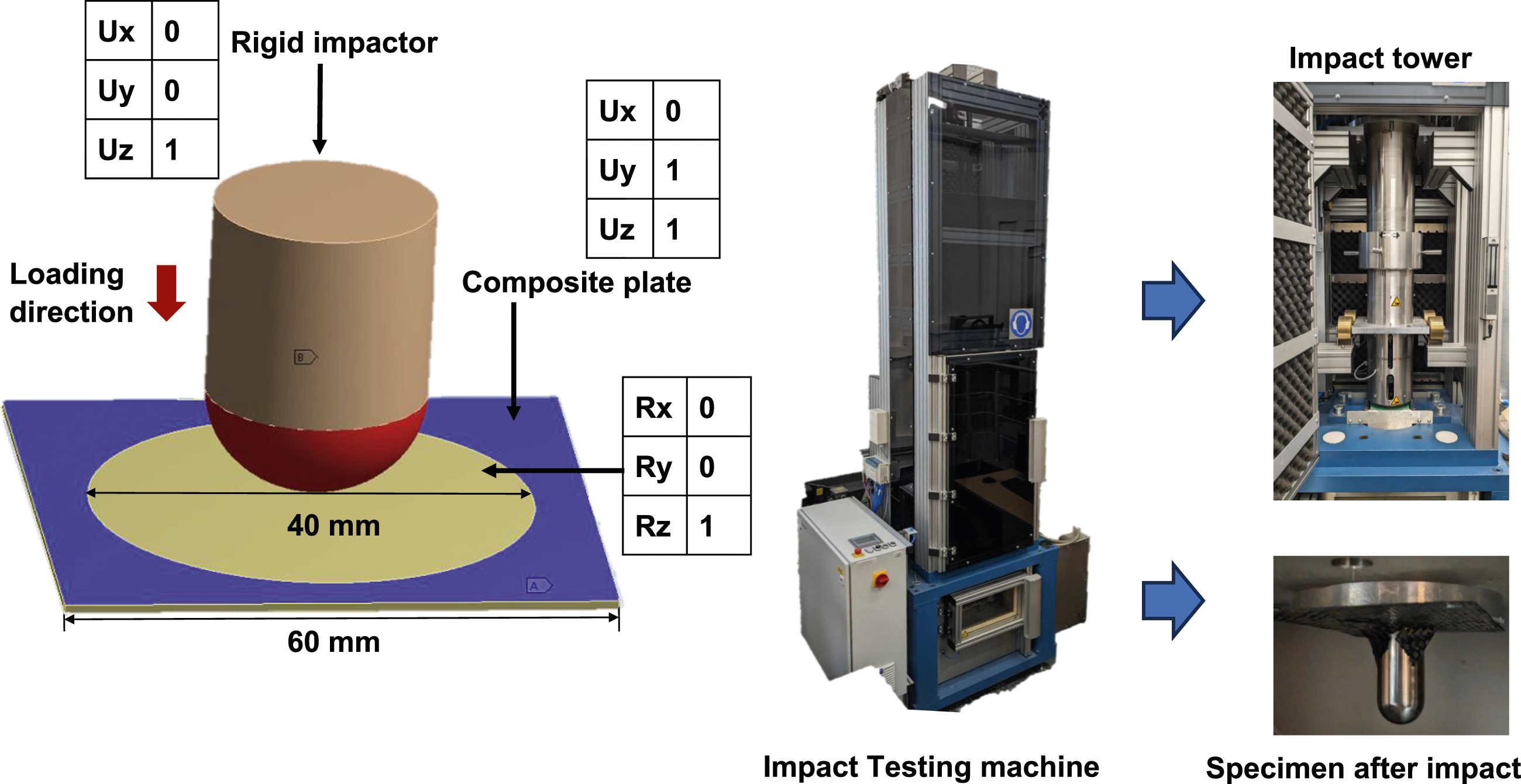
In the explicit dynamics module, the boundary conditions similar to impact drop tower as shown in Figure 4 were setup for all composite plate geometries. The impactor was assigned a point mass of 5.186 kg and 0.4 m drop height denoted by red colour. The composite plate geometry was assigned fixed support with linear and rotational constraints, similar to clamping of composites by the impact machine. The contact between the impactor and the composite plate was set to automatic surface to surface penalty based contact algorithm.28,32 The penalty contact algorithm takes into account stiffness matrix of the contact and the target surface. The contact stiffness K and restoring force F
c
are calculated by equation (5)
33
: Boundary conditions and impact testing machine.
The restoring force can be replaced with the contact force. Based on the stiffness factor, the contact pressure is defined by equation (6):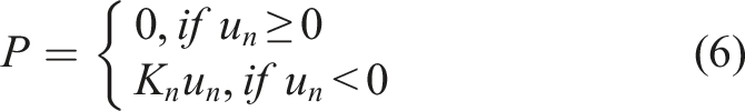
The frictional stresses in material directions τi (i = 1, 2) are obtained by equation (7):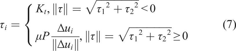
Where K t is contact stiffness in tangential direction, u i (i = 1,2) are sliding distances in lateral direction and µ is the coefficient of friction.
Mesh convergence study for plain woven composite geometry.
Results and discussion
Characterization of damaged area
The damaged samples of S1–S5 by impact loading were studied and presented in Figure 5. The manufactured specimens of S1–S5 can be observed in Figure 5(a), (d), (g), (j) and (m), respectively. It can be observed that the shape of the damaged area shifts from typical rhombus shape to a circular shape as the fibre orientation changes from 0 to 90 in S1 to 45/0/90 in case of S2–S5 as shown in Figure 5(b)–(o). The font surface of composite samples undergo high compression load where the matrix failure occurs first followed by fibre rupture, whereas the back surface undergoes high tensile stress which causes tensile failure.
34
From the damage area of S2 and S3 as shown in Figure 5(e), (f), (h), (i), it is evident that the impact energy dissipation is influenced by the fibre architecture. A closer look in damaged samples of S2 and S3 showed delamination, fibre rupture and matrix damage as principal failure modes. The damage area of S4 and S5 as presented in Figure 5(k), (l), (n), (o), shows that the principal failure modes were bias fibre pull out, fibre rupture, matrix cracking, with a lesser degree of delamination as compared to samples S2 and S3. This indicates that with a higher number of bias fibres incorporated in the composite, the impact energy dissipation is more uniform over the composite surface, similar to S2 and S3 and not concentrated towards the 0–90 fibres as in case of S1. Images of (a) S1, (b) front surface of S1 after impact, (c) back surface of S1 after impact, (d) S2, (e) front surface of S2 after impact, (f) back surface of S2 after impact, (g) S3, (h) front surface of S3 after impact, (i) back surface of S3 after impact, (j) S4, (k) front surface of S4 after impact, (l) back surface of S4 after impact, (m) S5, (n) front surface of S5, (o) back surface of S5.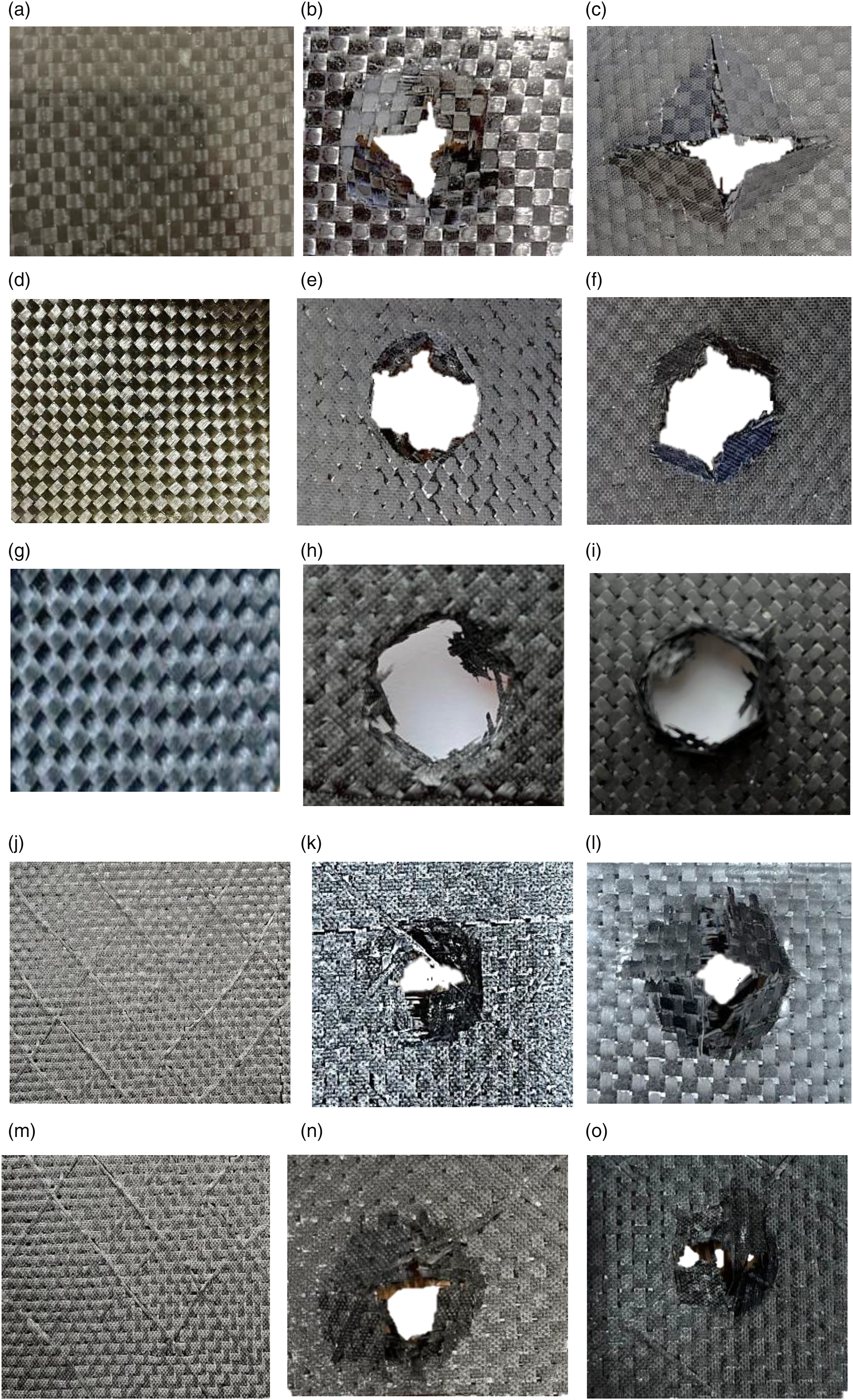
Force time history
The damage mechanism of impact loading is complex process involving fibre damage, matrix damage and delamination under tensile and compressive load. The previous research conducted on impact properties of carbon composites, with varying stacking sequence suggests that the plain-woven ply (0° and 90° fibre direction) exhibit the highest impact load bearing capacity as compared to other stacking sequences e.g., ±45°, 30°,60° etc. This is attributed to easy transfer of force from one layer to another between similar oriented plies. 26
The comparison of force-time curves of S1 with S2 and S3 is shown in Figure 6(a) and (b), respectively. The graphs indicate that S2 and S3 show yielding followed by stable crack growth indicating that the composite samples are more elastically deformed with addition of 45 ply. The sample S2 shows reduction of 7.3% in contact force as compared to S1 which can be attributed to increased difference in bending stress between dissimilar plies as shown in Figure 6(a). The peak contact force further decreases by 18.4% as dissimilarity increases on introduction of second ply oriented at 45° angle in S3 as shown in Figure 6(b). The failure of composite starts with onset of matrix cracking caused by tension, shear or compression.35,36 This also causes debonding of matrix from the fibres and its extent depends on the mismatch properties between matrix and fibres.
37
The delamination starts after matrix failure reaches its peak. With higher mismatch in bending stress and fibre orientations, the degree of delamination increases. As the impact penetrates more, the strain, bending and shear stress increases to a point where fibres break.37–40 Graphs comparison of Force time history of (a) S1 with S2, (b) S1 with S3, (c) S1 with S4, (d) S1 with S5.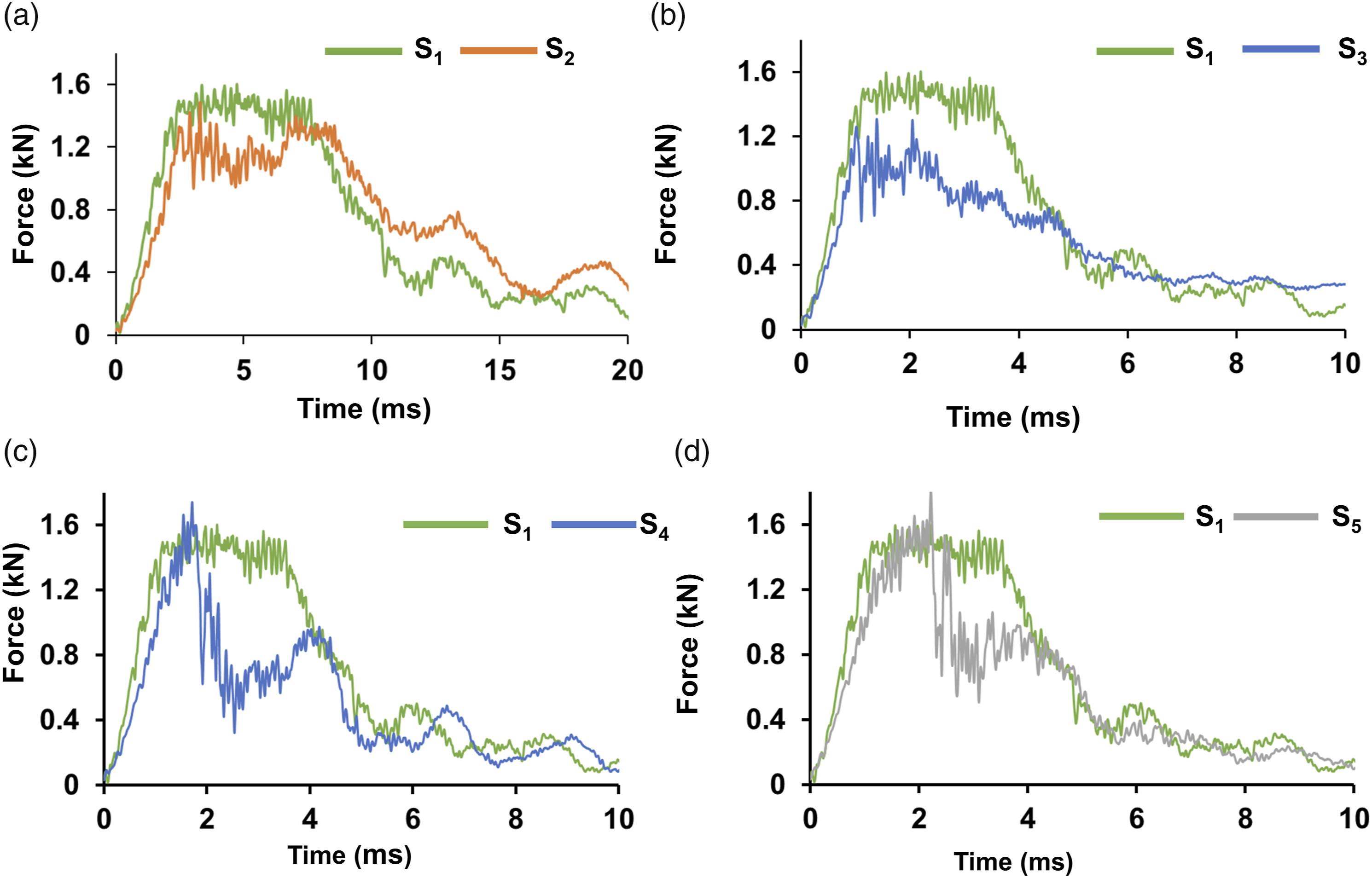
The force-time curves of S4 and S5 in comparison to S1 are shown in Figure 6(c) and (d). The graph in Figure 6(a) and (b) shows a decreasing trend of impact force for 45° angle ply laminates, whereas 45° multiaxis woven plies shows increasing trend in impact force. As the bias fibres are woven with base of plain weave, thus the dissimilarity between plies in the composite is eliminated. At peak contact force, the bias fibre provides additional reinforcement to the plain woven thus increasing the peak load by 8.6% which can be observed in Figure 6(c). The reinforcing effect of bias fibre is further enhanced by 12.9% on addition of second multiaxis ply in S5 as shown in Figure 6(d). These results agree with the previous research conducted on effect of alignment of fibre directions close to warp fibre.
26
The summary of peak loads values of all samples have been presented in Figure 7, which also shows that impact load increases with the addition of multiaxial plies. Summary of peak load values of all samples.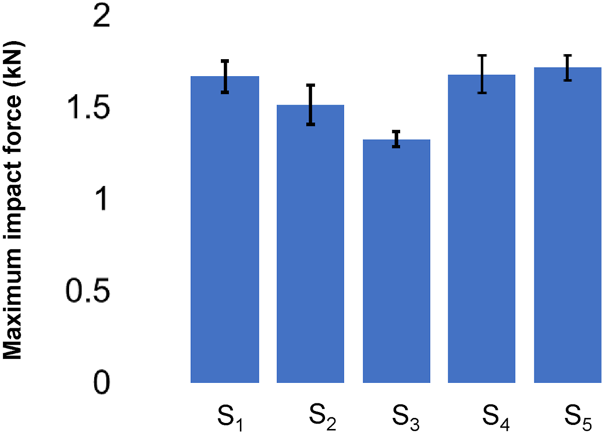
The numerical modelling as described in section 2.4 was able to generate results as shown in Figure 8. The model was able to capture force time history in elastic region and non-linear plastic zone with good precision. The difference between peak force values obtained was 3% in case of S1 composite, 6.3% for S2, 5.8% for S3 and 5% in case of S4 - S5 composite samples as shown in Figures 8(a)–(e). This can be attributed to errors during testing and vibration generated in the machine during testing. Also, in simulation model, the fix supported nodes are perfectly still whereas in actual testing the sample is not perfectly gripped by the machine during testing. The stress distribution of all composite samples before and after impact is shown in Figures 8(a)–(e). Comparison of experimental and numerical results (a) S1, (b) S2, (c) S3, (d) S4, (e) S5.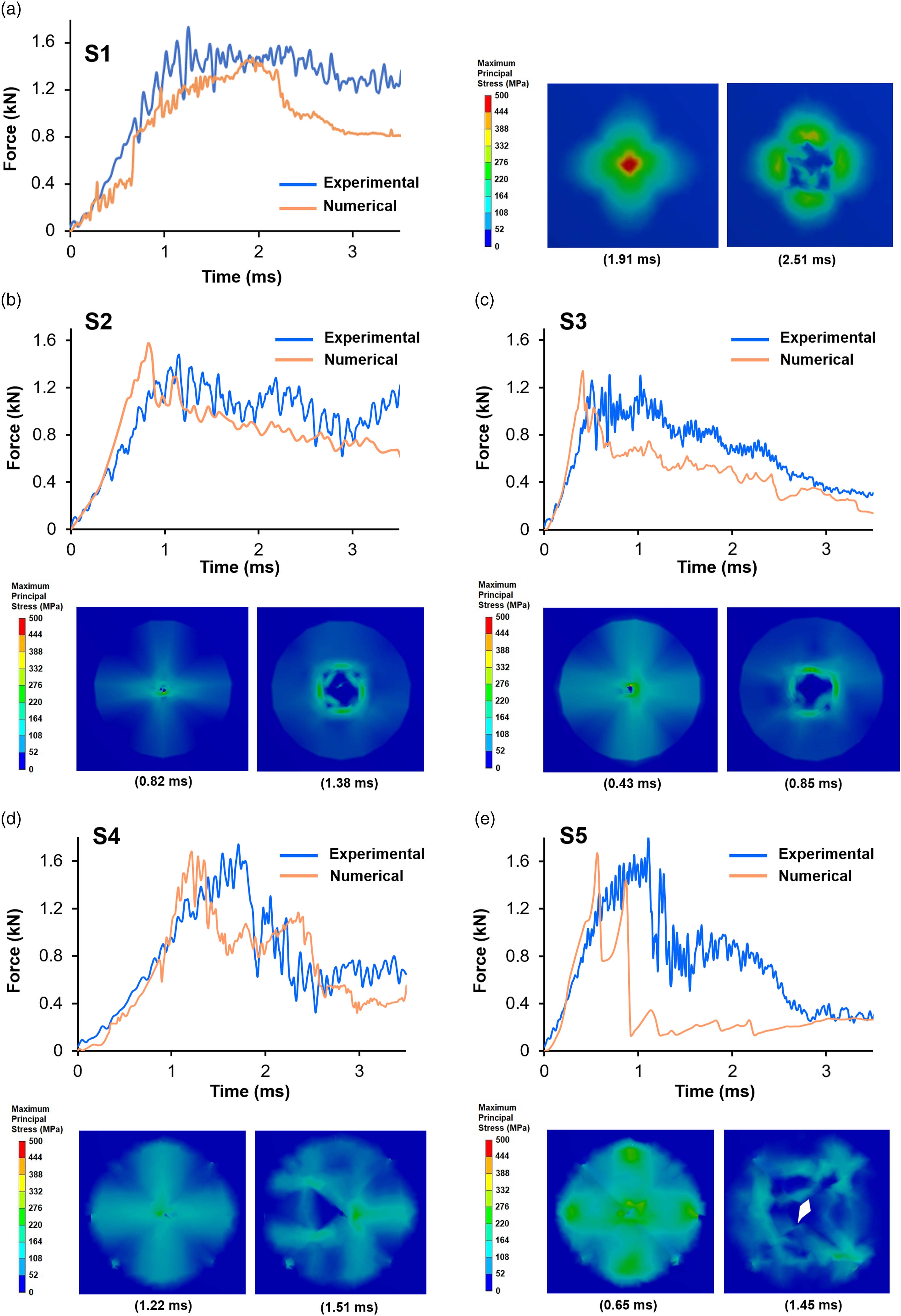
Absorbed energy
The impact energy absorbed by the composite is dissipated in various ways such as elastic and in-elastic deformation, delamination, crack propagation etc.
41
The energy vs time graph plotted is shown in Figure 9. It can be observed that impact energy absorption for S2 composite sample is 17.8% higher than S1. However, as the number of 45° ply increases, the impact energy is decreased by 4.7% observed in the case of S3 as shown in Figure 9(a). Similar trend has been observed in previous research conducted on the impact properties of carbon fibre composite materials.
25
It can be also observed from Figure 9(b) that the energy absorption of S4 and S5 is 8.9% and 18.3% higher than S1, respectively. Thus, these results show that multiaxis composites have intermediate energy absorption values between cross and angle ply laminated composites and enhances the damage tolerance of plain woven composites. Absorbed energy comparison of (a) S1 with S2 and S3, (b) S1 with S4 and S5.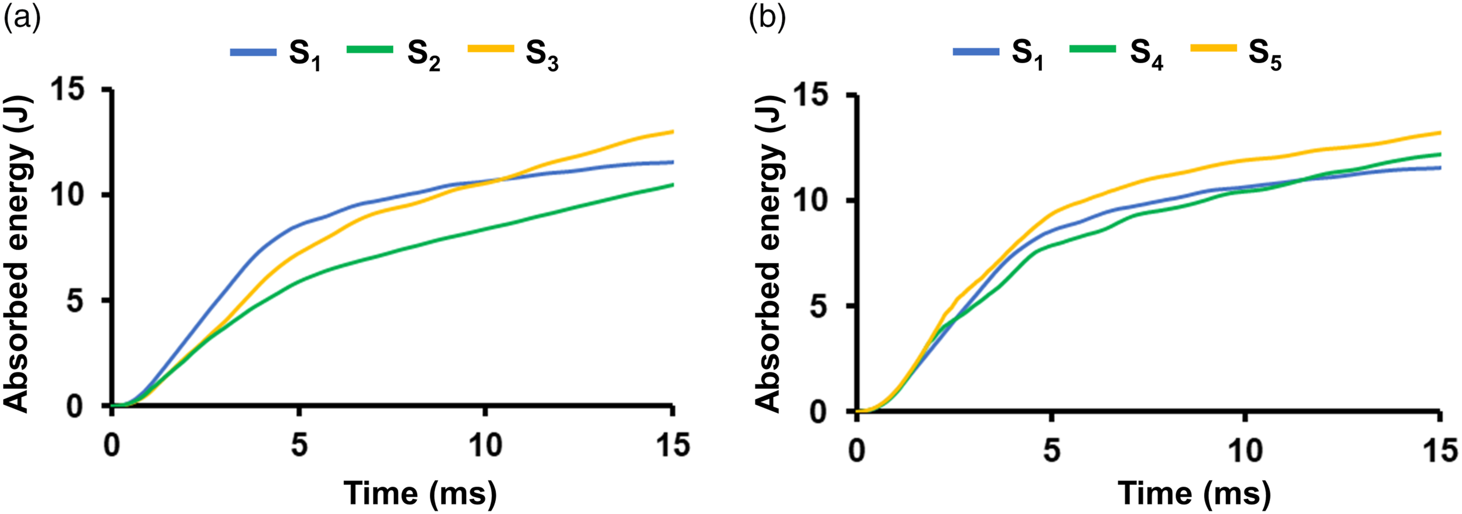
Conclusions
In this research work, a novel method of manufacturing multiaxis carbon fibre prefroms on conventional weaving machine was developed and impact tolerance of the ensuing composites was studied. The carbon fibre multiaxis preforms were infused in bisphenol F epoxy resin by hand layup method to manufacture composites. The carbon fibre multiaxis composites were subjected to impact loading and the results were compared with impact loading of carbon fibre cross and 45° angle ply stacked laminates. A finite element analysis model was also developed in Ansys v.19 to simulate the force-time history of impact loading of multiaxis composite. The following conclusions can be derived from this study. • The concept of partial insertion of weft in predetermined intervals is feasible for manufacturing multiaxis preforms on conventional weaving machine and eliminated the necessity of complex modifications in weaving machine. • The impact loading of multiaxis composites show increase in the impact force by 12.91% and impact energy absorption by 18.3% as compared to plain woven composites. • The force-time history of plain and multiaxis composite generated by FEA corroborated well with the experimental results within acceptable limits.
Footnotes
Declaration of conflicting interests
The author(s) declared no potential conflicts of interest with respect to the research, authorship, and/or publication of this article.
Funding
The author(s) received no financial support for the research, authorship, and/or publication of this article.
Data Availability Statement
Data sharing not applicable to this article as no datasets were generated or analyzed during the current study.