
Abstract
Carbon fiber reinforced thermoplastics (CFRTP) have increasing use in aerospace structures due to improved process-ability and weldability. In this study, lap joints between carbon fiber reinforced low-meltpolyaryletherketone (LMPAEK) are formed by friction stir welding (FSW). This study presents novelty by applying FSW to continuous carbon fiber composites in woven laminate form. FSW disrupts the fibers in the weld zone and distributes fragments as small as several microns in length. Thermal analysis shows that the weld zones degrade at 40°C cooler temperatures than the base laminate material due to enhanced polymer mobility surrounding the disrupted carbon fibers. Though optimized joints have regions of over 9% porosity, tensile strengths of up to 73.8 MPa retains up to 50% joint efficiency of a comparable short carbon fiber reinforced composite. CFRTP also requires lower processing forces during FSW than metals, and the power consumption of 67 W during the traverse period for strength optimized welds retains energy efficient characteristics.
Keywords
Introduction
Implementing lightweight structures into aerospace vehicles is imperative to increase cargo capacity and improve efficiency. Carbon fiber reinforced plastics have increasing popularity due to improved specific strength, corrosion resistance, and damping capacity 1 that allows for a 20%- 40% weight reduction compared to conventional metallic materials. 2 Carbon fiber reinforced thermoplastics (CFRTP) have growing attention in aerospace industries due to non-definite shelf life, rapid cure times, high tensile strength, high fracture toughness, and good chemical resitance.3,4 Unlike thermosetting polymer matrices, the molecular arrangement in thermoplastics allows them to re-melted, re-processed, and ultimately, welded. Aerospace structures regularly use polymer matrices from the family of polyaryletherketones (PAEK) such as PEEK and PEKK due to their attractive mechanical properties, chemical resistance, and glass transition temperatures suitable for aerospace applications. Most PAEK’s have a ratio between the melting and glass transition temperature of 1.5. Their high melting temperatures make them difficult to process and weld. Recently, low-melt polyaryletherketone (LMPAEK) was developed with a reduced ratio between the melting and glass transition temperature of 1.35. 5 LMPAEK is easier to process and weld than PEEK with little compromise to mechanical properties and rigidity at high temperatures. The Clean Sky 2 Multifunctional Fuselage Deomstrator 6 and PROCOMP’s upper stage LH 2 propellant tank 7 are examples where LMPAEK serves as the matrix in welded composite structures.
Recently, extensive research has explored joining various fiber reinforced thermoplastics using friction stir welding (FSW). FSW utilizes a rotating tool plunged into the joining materials to heat and soften them through friction and plastic deformation. 8 The rotating tool sweeps and mixes the joining materials in the weld zone. Because intertwined polymer chains require them to be melted during thermoplastic welding processes, FSW is a liquid state joining process for polymer composites. 9
A typical FSW joint contains several zones including the base material, heat affected zone (HAZ), thermo-mechanically affected zone (TMAZ), and the nugget. Most polymer weld joints do not have a heat affected zone extending beyond the TMAZ due to their extremely low thermal conductivity. Without consideration of finely tuned welding parameters, inadequate heat transfer through the weld thickness can induce poor material flow and poor polymer diffusion, resulting in tunneling, porosity, root defects, and kissing bonds that hinder mechanical strength.9,10
The tool rotation speed and traverse speed affects the size of the material flow zone in a polymeric FSW joint which has been shown to correlate with weld strength. 11 Though many parameters ultimately affect joint integrity, a general consensus is that the tool rotation and traverse speeds are of greatest influence. 12 Tool rotation speed is responsible for heat generation. 13 Kordestani et al. joined both 30% wt. glass fiber and 30% wt. carbon fiber reinforced polypropylene in butt weld configuration, citing large tunneling defects when using low rotation speeds due to inadequate processing temperatures. 14 However, too high of a rotation speed can overheat and eject materials from the weld zone. 15 Not only can overheating the polymer oversoften it, but it can also thermally degrade the polymer in the form of oxidation, cross-linking, and chain rupture that ultimately leads to losses in mechanical properties and changes in appearance. 16
The tool traverse speed is the most influential in controlling the heat transferred through the material thickness. 11 Slow traverse speeds maintain a molten polymer pool behind the tool and further promote interdiffusion across the joint. 10 Ahmadi et al. joined 20% wt. short carbon fiber (SCF) reinforced polypropylene in lap joint configuration. 17 A maximum tensile shear strength of 6.06 MPa was achieved through parameter optimization, with the traverse speed as the greatest contributor to strength. Other influential welding parameters include the tool tilt angle and plunge depth. The tool tilt angle is usually considered when utilizing shouldered tools as it influences vertical and horizontal material flows.14,18 The plunge depth dictates the degree of pin interaction with the joining material as well as the forging pressure of the shoulder at the surface. 19 Adequate axial pressure promotes material consolidation necessary to prevent formation of voids and other defects. The tool shoulder and pin geometry influence heat generation and material flow. Required spindle torque and peak temperatures have been shown to be proportional to shoulder diameter. 20 Additional shoulder features, such as spiral scrolls, can act as wipers to smooth the weld surface. They can serve the purpose of directing material towards the center pin and reduce expulsion of material. 21 Researchers have excessively studied the influence of center pin geometry during polymer FSW. Of all pin geometries, threaded probes generally result in the best weld quality since they promote vertical flow of material that adequately mixes the weld zone. Threaded pins also have a large surface area to generate frictional heat and ultimately produce the least porosity of other pin geometries. 12 Kordestani et al. studied the effects of tool pin geometry on butt welded joints between similar 30% wt. SCF reinforced polypropylene. Tools with threaded tapered pins produce the maximum tensile strength, achieving up to 34% of the base composite’s strength. 22
Reinforcing fibers add complexity to polymeric FSW due to fiber disruption. Carbon fiber is an extremely abrasive material 23 and causes premature wear on standard FSW tools made of H13 tool steel. 24 Fiber disruption during FSW and related processes also reduces fiber size and changes their reinforcing properties.25–27 For example, General Motors Global R&D report 50% reduced fiber length in the weld zone of friction stir scribe joined SCF 45-polyamide 6 and aluminum.
The critical fiber length L
c
is the minimum length of reinforcing fiber that improves the mechanical strength over the neat polymer. L
c
can be calculated by equation (1):
26
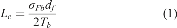
σ F b is the fiber breakage resistance, d f is the diameter of the fiber, and τ b is the shear strength of the polymer. According to Meyer et al. fragmentation and reduction of glass fiber length below the critical fiber length in the weld zone limits the joint strength to that of the neat polymer. 26 However, fiber disruption in FSW joints can be beneficial to mechanical properties due to realignment of fibers. Czigany et al. observed random deposited fiber orientation and interlacing across the joint in glass fiber reinforced polypropylene. The unique material transfer during FSW was attributed to improved joint strength compared to conventional welding methods. 25
There are a limited number of studies concerning FSW joints between similar CFRTP. Additionally, the majority of studies joining CFRTP use SCF reinforcement. However, most large aerospace structures manufactured with CFRTP utilize continuous fibers, both in laminate and unidirectional tape form. Thus, a greater focus on welding technologies to join CFRTP composed of continuous carbon fibers is necessary to meet the needs of future aerospace industries. FSW lags behind other welding technologies for thermoplastic applications, though it may prove to be highly beneficial in joining thermoplastics reinforced with continuous carbon fibers. This study is the advent of such research with the formation of woven carbon fiber reinforced LMPAEK lap joints using FSW. Parameter optimization of tensile strength, morphology characterization, and thermal analysis lay the groundwork for future study and identify areas of necessary improvement.
Material and methods
Materials
Carbon fiber reinforced low-melt polyaryletherketone (LMPAEK) sheet supplied by Toray Advanced Composites served as the joining material in this study. Four layers of Toray Cetex TC1225 2/1 twill weave in [(0.90)]2S layup composed the laminate sheets with a thickness of 1.2 mm. Figure 1 illustrates the orientation of the fabric weave with respect to the 0
◦
and 90
◦
directions. Cut laminate sheet dimensions and respective fiber orientations.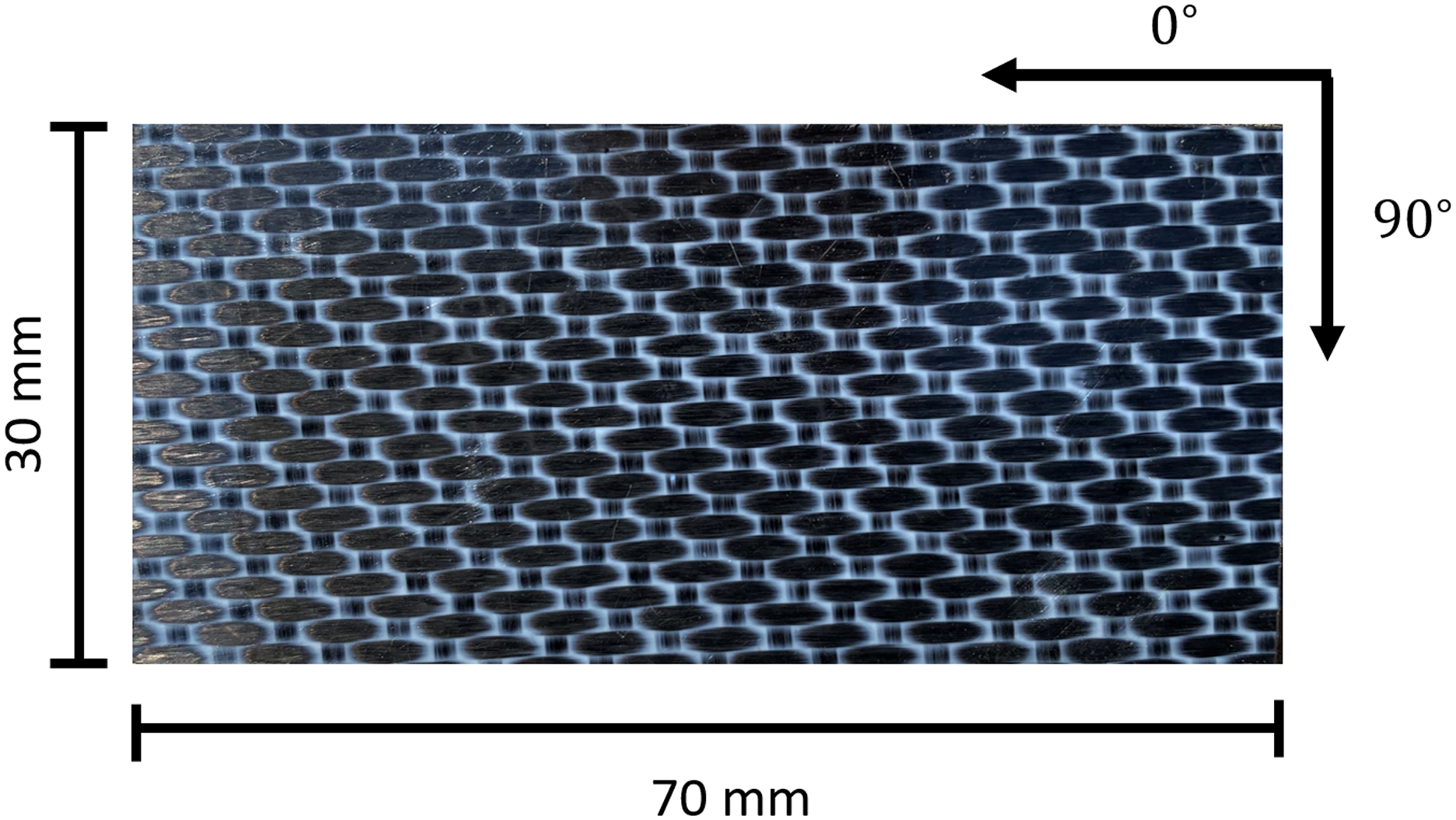
Specimens were cut to dimensions of 30 mm × 70 mm using a wet tile saw with a diamond tipped blade. Due to the abrasive nature of carbon fibers and risk of delamination, the tile saw provided the highest quality cuts over other cutting methods available. The cut sheets were lapped along the 0 ◦ direction with a 15.75 mm overlap. FSW was conducted using a Simulink controlled modified Kearney and Trecker Milwaukee Model K milling machine at the Vanderbilt University Welding Automation Lab (VUWAL). The tool consisted of a 25.4 mm scrolled parabolic shoulder and removable 6.35 mm diameter threaded pin set to 1.14 mm in length. The threads had a pitch of 0.79 mm (32 TPI) in the left-hand orientation, facilitating downward material flow during a clockwise rotation. 28
Preliminary experimentation
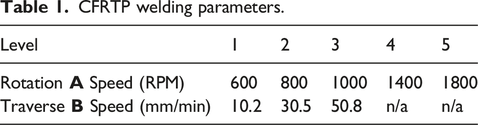
CFRTP welding parameters.
Parameter experimentation
The effects of tool rotation speed (A) and traverse speed (B) were tested in a 2 parameter, full-factorial design of experiments. Table 1 lists the ranges of A and B. Levels 3-5 were originally of interest for parameter A based on a similar range used by other researchers. 27 However, levels 1 and 2 were later added to capture the effects of lower rotation speeds. A minimum of three replicate welds for each parameter combination performed in separate blocks accounted for unintended environmental variations.
Evaluation
Mechanical tests consisted of tensile testing on an Instron load frame. Specimens were cut 14 mm wide across the lap welded sheets using a wet diamond saw with a 10 mm minimum distance from the plunge location. Two tensile specimens were cut from each weld. Emory cloth bonded to carbon fiber pads compensated for the lapped sheet offset during tensile testing. The load frame crosshead travelled at a constant 2 mm/min according to the ASTM designation D3039-08. Microstructure characterization consisted of optical microscopy and scanning electron microscopy (SEM). Weld cross sections were sanded with up to 600 grit sand paper. Polishing with 5 µm and 1 µm particle slurries concluded the surface preparation. Particle sizing and dimensional analysis was performed using ImageJ. Thermogravimetric analysis (TGA) and differential scanning calorimetry (DSC) was used for thermal analysis on a TA Instruments Q600 SDT. Neat laminate and weld zone specimens were clipped using diagonal pliers. Analysis used heating curves sweeping from 20°C to 600°C at a rate of 10°C/min. Welding forces in the axial, lateral, and traverse directions and spindle torque were measured using a Kistler type 9123C dynamometer mounted to the machine spindle. Figure 2 references the welding directions with respect to the weld setup. Schematic of welding setup. The dynamometer measures forces in the axial (Z), lateral (Y), and traverse (X) directions in addition to the torque around the rotation axis. The weld direction goes from right to left.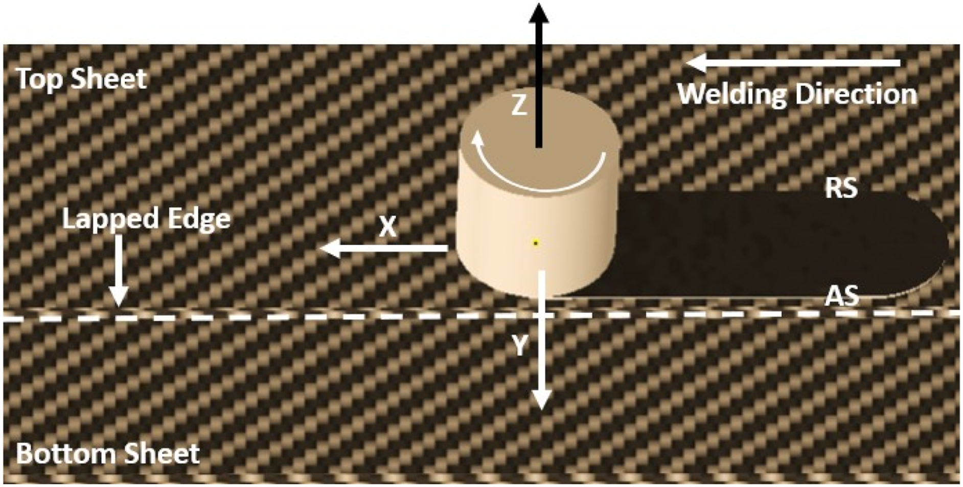
Parameter effects on mechanical properties and welding forces were analyzed using Minitab Statistical Software, where a parameter’s statistical significance was evaluated on a 95% confidence interval (p ≤ .05).
Results
Surface Integrity
Figures 3(a), 3(b), and 3(c) display the surface appearance of multiple welds with varying parameters. Generally, FSW created joints with smooth and consistent surfaces for most parameter combinations. Severe surface delamination was characteristic of 600 RPM and 800 RPM welds and welds with 50.8 mm/min traverse speeds. The delamination results from cold welding parameters that fail to provide the thermal input necessary to promote polymer diffusion. Welds with the parameter combination of 1000 RPM and 30.5 mm/min had the most consistent and highest quality top surface appearance. Excessive flash occurred during 1800 RPM welds due to over softening of the material. This material expulsion reduced shoulder contact with the top surface and formed voids and inconsistent surface appearance from the lack of forging pressure. Figure 3(d) shows the underside of the welded sheets. The weld zone does not penetrate through the entire thickness of both sheets, leaving a completely unaltered surface appearance under the weld zone. Figure 3(e) shows an edge on view of the lap welded sheets. Typical surface appearance of selected welds. (a) 800 RPM (b) 1000 RPM (c) 1800 RPM (d) Bottom view (e) End view.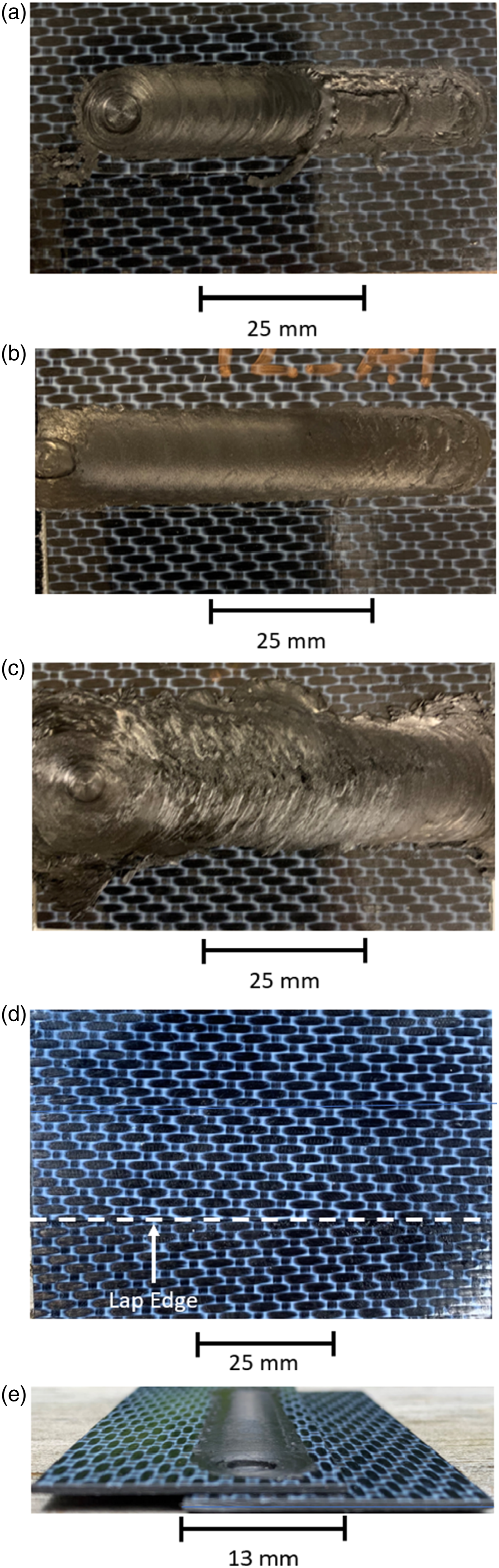
Microstructure
FSW influences non-homogeneous material morphology throughout the width and thickness of the weld as a result of mechanical material interaction with the tool and variable processing temperatures. Figure 4 reveals the cross section of a welded specimen with 1000 RPM and 30.5 mm/min parameters. All weld parameter combinations present similar morphological characteristics as those presented in Figure 4 from a wide view, though further discussion highlights parameter influence at microscopic scales. 1000 RPM, 30.5 mm/min weld specimen cross section.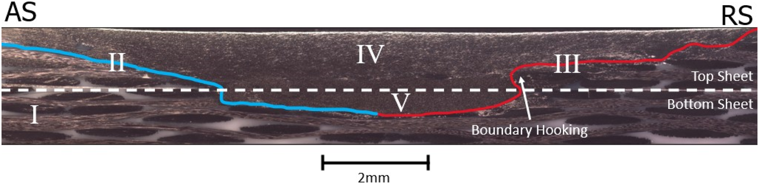
The weld cross section can be characterized into five distinct zones. Zone I represents the base material (BM) outside of the thermomechanically affected zone (TMAZ). Regions II and III represent the boundary between the TMAZ and BM, where region II lies at the advancing side (AS) interface and region III lies at the retreating side (RS) interface. The TMAZ comprises regions IV and V, where the shoulder affected zone (SAZ) lies in region IV and the pin affected zone (PAZ) extends into region V. Region V primarily lies within the bottom laminate sheet.
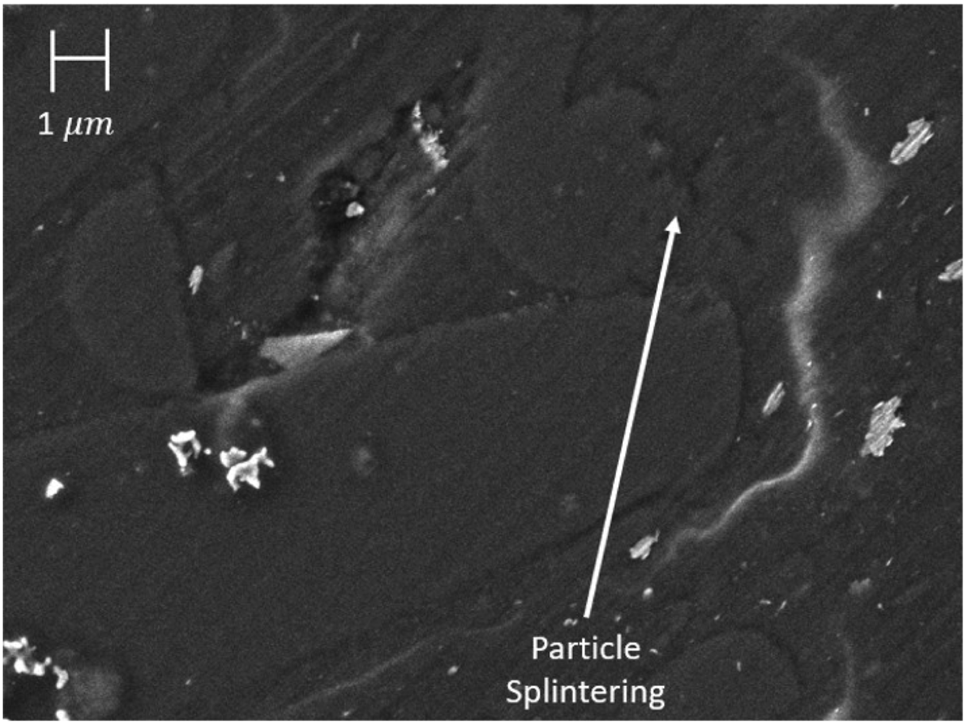
The composite laminate undergoes heavy transformation in the TMAZ since the FSW process must disturb the fibers in order for mass material flow and mixing to occur. Material flow is complex as the polymer has a sharp temperature dependent gradient between a solidus state, a highly ductile material, and a liquid, while the continuous carbon fibers are processed into short particles. Shearing effects further reduce fiber sizes post fragmentation from the long fibers. Figures 5 and 6 show the transformation of continuous fibers to small fragments. In Figure 5, the continuous fibers have relatively uniform circularity with a 7µm diameter. In Figure 6, chopped fibers show splintered surfaces of variable sizes encapsulated in the matrix. SEM cross section of carbon fiber laminate. The fibers are oriented normal to the page. SEM micrograph of the stir zone cross section. Broken fiber ends show splintering.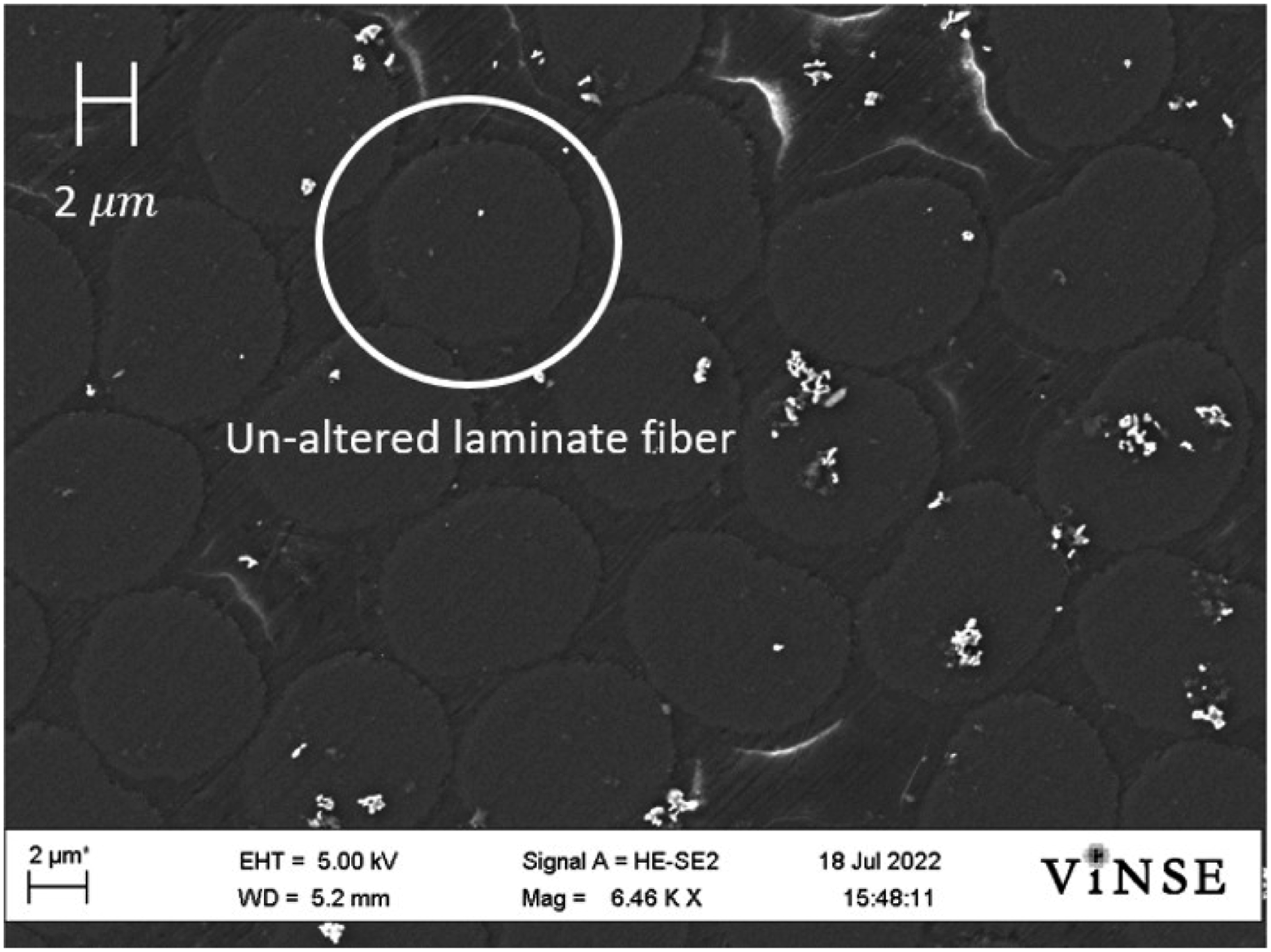
Flow stresses orient the fibers to the flow field. 27 In region IV, fibers up to 150 µm long orient primarily parallel to to the weld cross section. The shoulder sweeps the fibers in region IV and deposits them tangent to the shoulder’s aft end, thus orienting many of the fibers across the weld. Fiber orientation in the weld is analogous to injection molding of SCF composites. It has been shown that SCF’s located near part/mold edges tend to orient parallel to mold walls in the flow direction, resulting in the part’s mechanical properties favoring that of the fiber orientation. 29 Thus, particles in the center of the weld zone orient mostly across the joint, while particles near the edges of the weld zone favor orientation to the weld seam.
Void content and carbon fiber particle dimensions for regions IV and V.
From equation (1) the critical fiber length L c is estimated to be 81µm, where σ F b = 3530 MPa, 31 d f = 7 µm (measured from the fiber diameter in Figure 5), and τ b = 152 MPa. 32 These results suggest that the longer fibers in zone IV provide greater reinforcement than zone V.
Figure 4 shows an asymmetry between the weld advancing side (AS) and retreating side (RS). In this instance, the RS presents a hooking effect around fiber clusters along region III, resulting in region III having approximately a 20% longer interface from weld center to the weld surface than region II. The weld asymmetry results from greater stresses on the AS than the RS, contributing to higher temperatures.10,33 The higher temperatures on the AS in turn lead to greater polymer mobility 11 and allows for improved sweeping of carbon fibers along the weld zone interface.
The weld shown in Figure 4 has the greatest ultimate strength of all tested parameter combinations, which is further discussed in section Mechanical Properties. However, microscopic images reveal substantial defects and voids in the polymer matrix that vary in size and prevalence depending on the location in the weld. Voids in the matrix occur from poor matrix mobility due to insufficient heating
27
and uneven cooling rates.
34
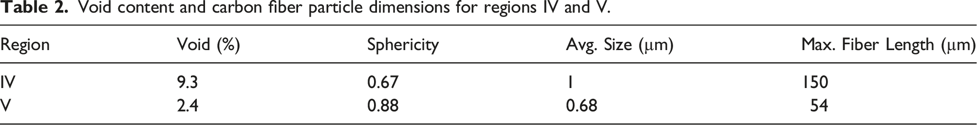
Figure 7 shows a large void that occurs along region II. A fiber cluster frozen in the solid base material has partially exposed ends in the SAZ. Material flow in the SAZ induces tugging on the exposed fibers, but low temperatures prohibit the polymer and chopped fibers from replacing the displaced fiber cluster. Large void visible along the AS from fiber tugging.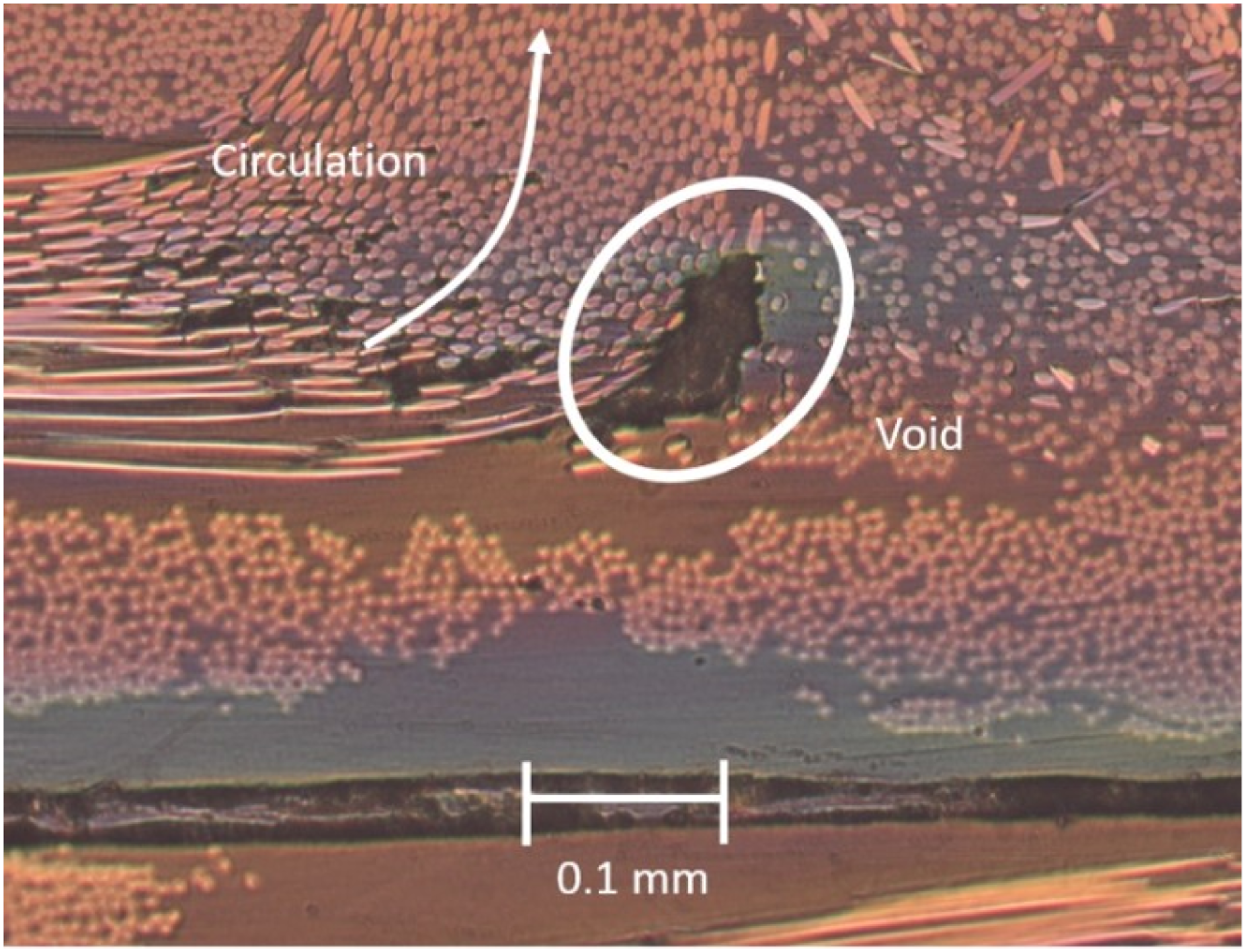
Large voids are especially common along region III which is characteristic of the RS in polymer FSW. These voids develop due to lower processing temperatures and lack of swept material forging around the back of the tool compared to the AS.
9
Tool rotation and traverse speeds have pronounced contribution to the prevalence of voids along region III. Figure 8 compares region III defects between two sets of parameters. Figure 8(a) demonstrates a cold weld fabricated using the lowest tested rotation speed and fastest traverse speed. It is well understood that the rotation speed affects heat input, while the traverse speed dictates the thickness of heat diffusion.11,35 Thus, too fast of a traverse speed outpaces the thermal conductivity of the composite, resulting in enhanced void formation. Figure 8(b) shows the same region fabricated from a faster rotation speed and slower traverse speed, allowing for more bulk melting and consequently a reduction in void size.
11
The void locations shown in Figure 8 correspond to the fracture location described in section Fracture Surface, indicating these defects are the main source of joint failure initiation. Fracture initiation locations. Scale bar applies for both sub figures. (a) 600 RPM, 50.8 mm/min weld (b) 1000 RPM, 30.5 mm/min weld.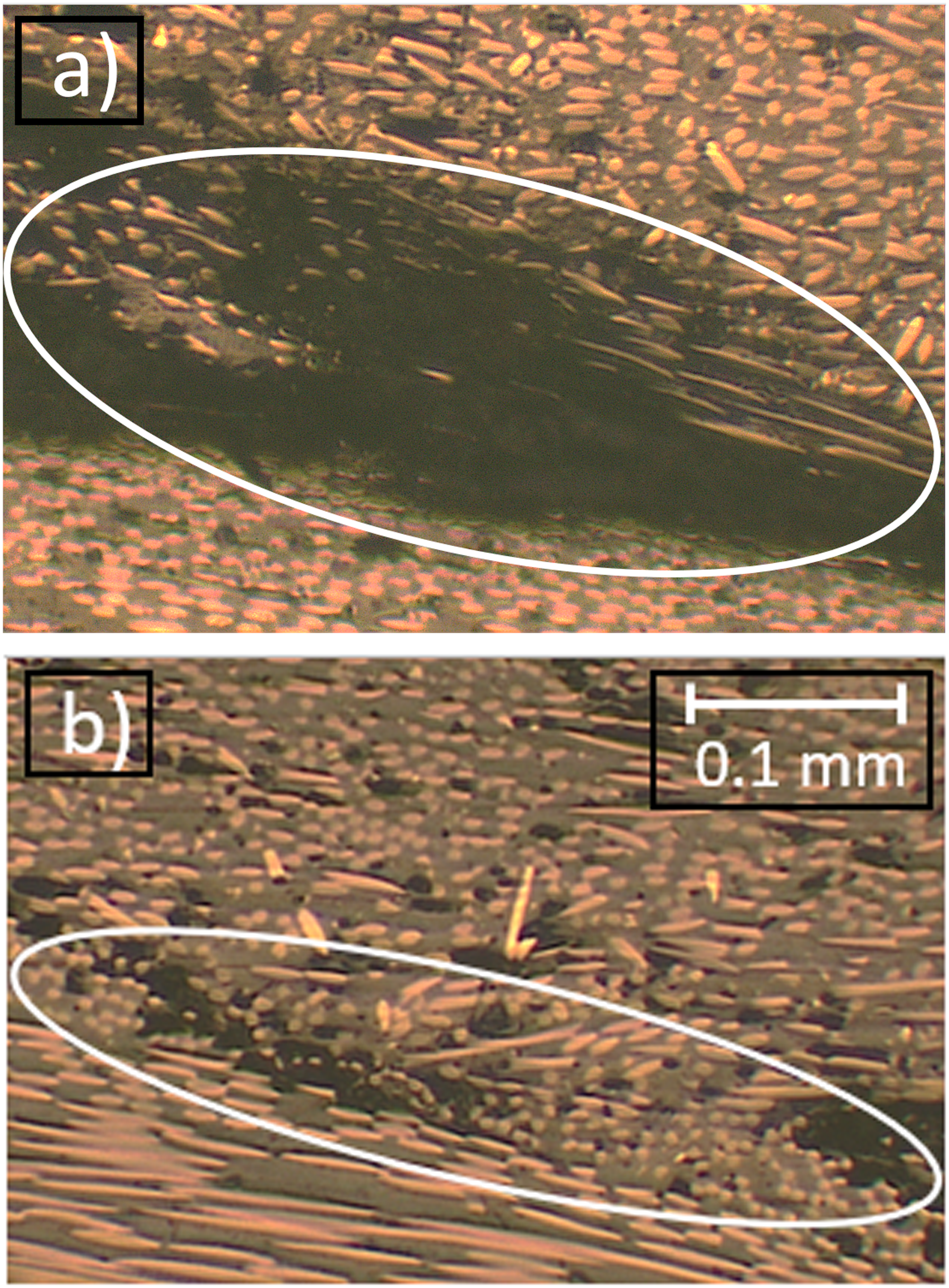
Microvoid content typically increases with material depth during polymer FSW with shouldered tools due to the inverse relationship between processing temperatures and weld depth that promotes less polymer mobility.11,35 However, Figure 9 shows a conflicting trend compared to those typically observed in polymer FSW. White highlights improve the void visibility for the reader. Region IV (Figure 9(a)) has a 9.3% void content, while region V (Figure 9(b)) has a 2.4% void content. The discrepancy in void distribution compared to conventional polymer FSW is the advent of variable fiber size fabricated by in-situ processing. Reduction in fiber size increases particle sphericity. Typically, processing of particles with greater sphericity results in a lower fraction of voids in a composite since the flowing polymer can more easily displace voids and encapsulate particles.
36
Thus, higher average particle sphericity in region V contributes to the lower void fraction. a) Region IV (void content 9% b) Region V (void content 2%) (c) Bottom of stir zone. Void regions are artificially colored with white overlays to highlight them. Scale bar applies for all three subfigures.
Figure 9(c) shows a trend common to conventional polymer FSW and polymer composite FSW with a lack of material consolidation at the bottom of the PAZ. This region has the coolest processing temperatures, limiting bulk material melting between the PAZ and ultimately limiting interdiffusion across the interface. 35
Mechanical properties
Fracture Surface All specimens failed under stress via tensile fracture along the RS, shown in Figure 10. This region is essentially an SCF composite bridging the continuous fiber laminate and the cross-sheet boundary region. Since the disruption of fibers inherently weakens the laminate, this region is the weakest on a lapped carbon fiber FSW joint non-exclusive to the advancing or retreating side configuration. Therefore, the joint tensile strength with the sheet thickness used in this study depends on the integrity of the weld in the top sheet rather than the shear strength between the lapped sheets. a) Top view of fractured specimen. (b) Cross section of fractured specimen.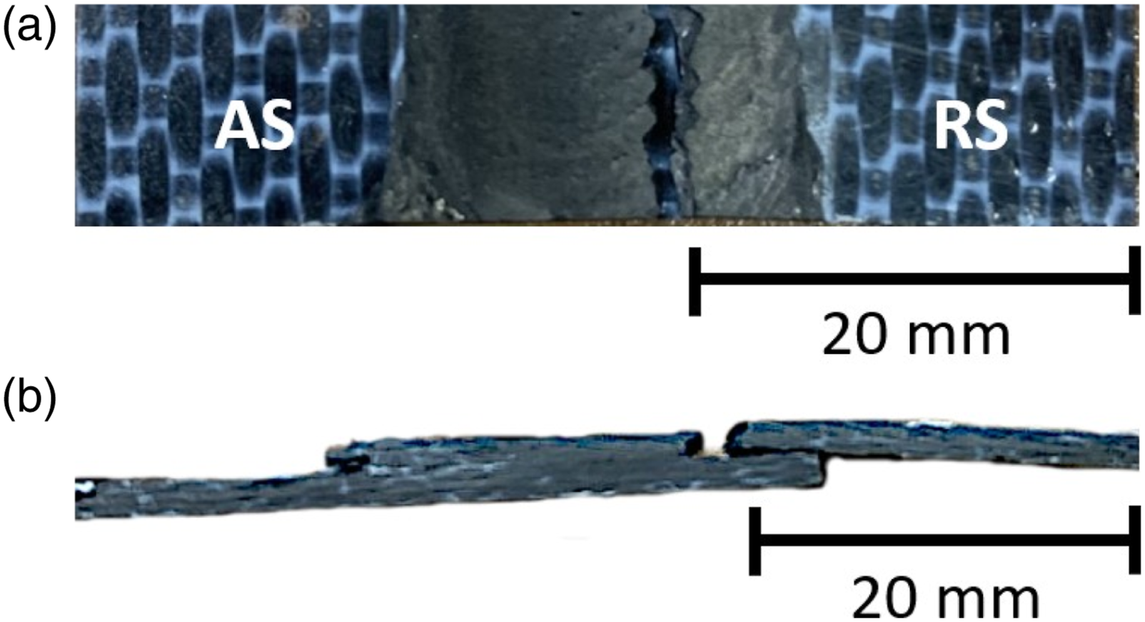
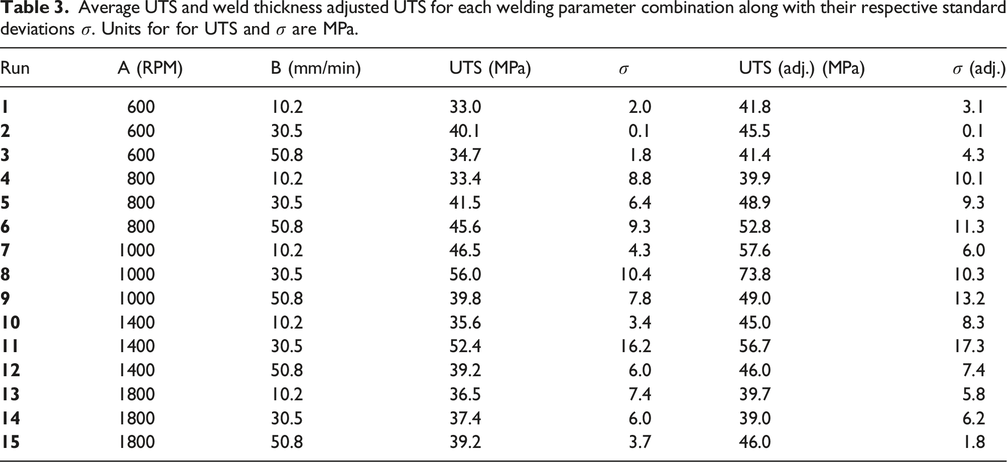
Average UTS and weld thickness adjusted UTS for each welding parameter combination along with their respective standard deviations σ. Units for for UTS and σ are MPa.
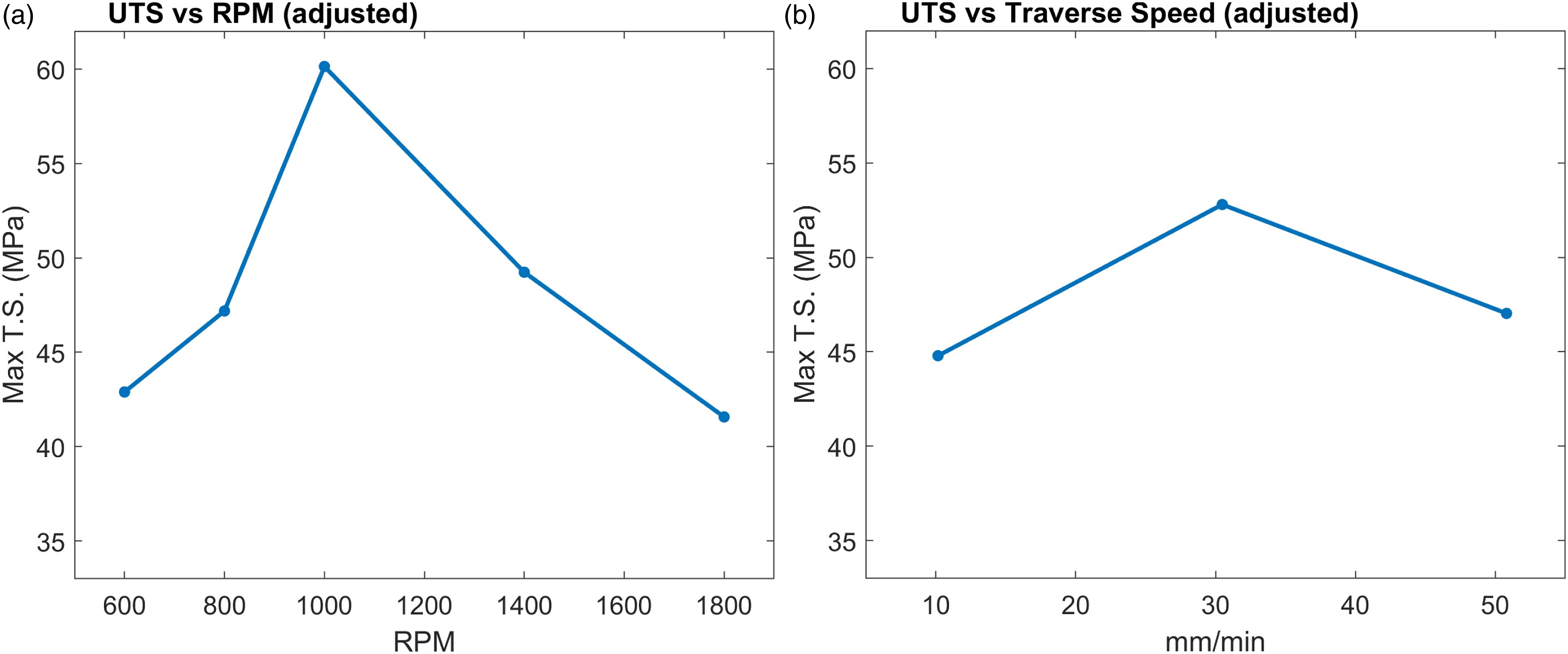
Parameters A and B have quadratic effects on the ultimate tensile strength, making the necessity of testing a minimum of three parameter levels apparent. Figure 11 plots the average effects of each parameter on UTS and Figure 12 does similarly for UTS adjusted. Fitted mean effects on the effective ultimate tensile strength from (a) rotation speed and (b) traverse speed. Fitted mean effects on the thickness adjusted ultimate tensile strength from (a) rotation speed and (b) traverse speed.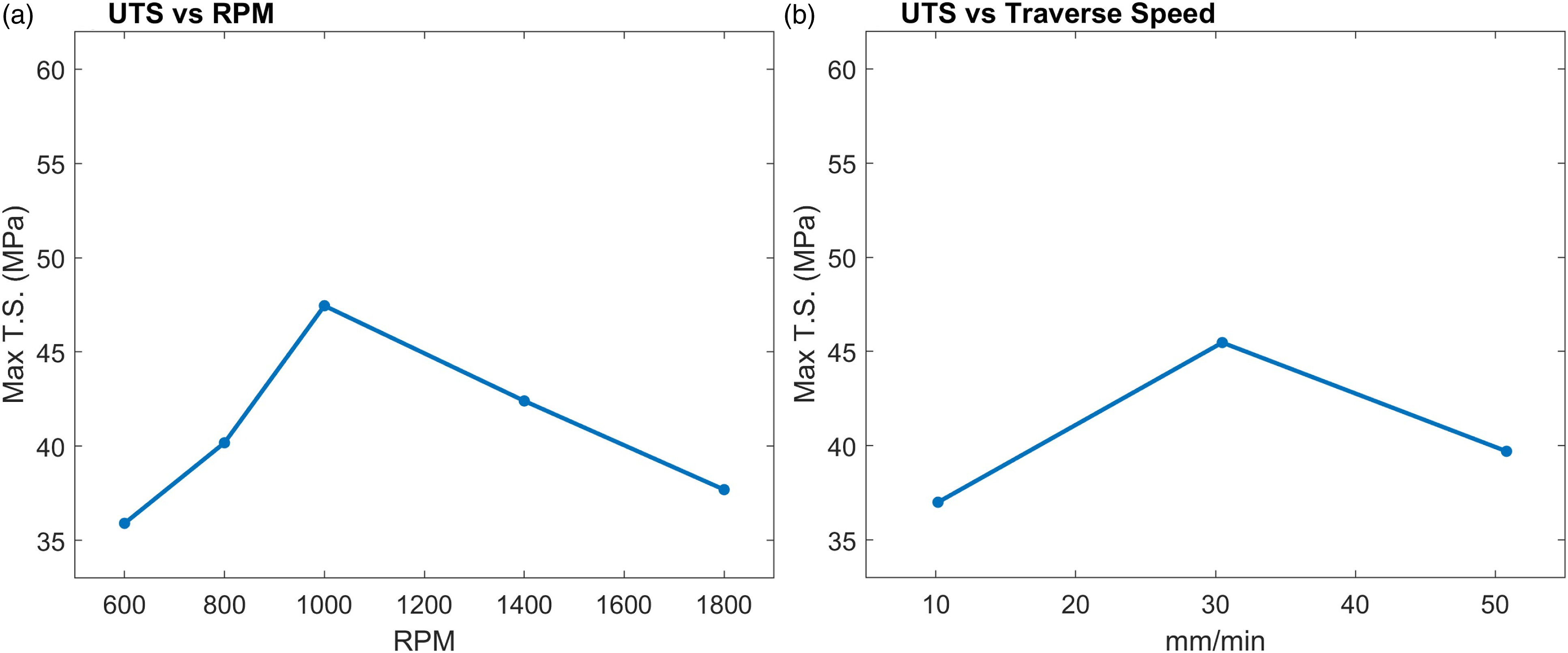
The three originally tested tool rotation speeds did not produce quadratic effects on the UTS as hypothesized. 600 RPM and 800 RPM runs added curvature to the mean effects on UTS, placing 1000 RPM at the maxima. These results differ from those in a similar study, 27 but the rotating shoulder in this work generates more heat at lower RPM’s.
Weld parameters of 1000 RPM and 30.5 mm/min consistently formed the strongest joints with 56.0 MPa average effective UTS and 73.8 MPa average thickness adjusted UTS. Tool rotation and traverse speeds often produce the greatest contribution to weld strength in polymer FSW 15 due to their influence on thermal input, mechanical interaction, and and material consolidation. 600 RPM and 800 RPM rotation speeds lacked sufficient thermal input from friction and plastic deformation to promote polymer diffusion across zones II and III. 1400 RPM and 1800 RPM rotation speeds have greatly accelerated work piece velocities that promote excessive void formation and material expulsion. A 1000 RPM rotation speed provided sufficient thermal input without overly agitating the weld pool. Likewise, the traverse speeds influence curved behavior on the UTS. A low pressure zone follows the tool during FSW, which can limit polymer adhesion in the weld zone with fast traverse speeds. 37 Slow traverse speeds allows for more contact time between the molten polymer pool and joining surfaces. However, traverse speeds also influence the amount of thermomechanical stress, and it has been shown that a faster traverse speed can use the enhanced thermomechanical stress to further distribute particles in composites. 38 Therefore, it appears that the 30.5 mm/min traverse speed balances the effects of thermomechanical stress induced particle distribution and polymer weld pool contact time.
The tensile data presented considerable variation between replicate welds and between replicate tensile specimens within the same weld. Runs 8 and 11 had the greatest non-adjusted variation with standard deviations of 10.4 MPa and 16.2 MPa, respectively. Runs 8 and 11 also had the two highest non-adjusted average tensile strengths at 56.0 MPa and 52.4 MPa but had tensile specimens with strengths of up to 68.0 MPa and 80.2 MPa, respectively. Adjusted UTS values contributed to additional variation within parameter sets since the small tensile cross sections have high sensitivity to calculations. There was no correlation to the tensile specimen strength with respect to its location along a weld. In other words, tensile specimens cut closer to the initial weld plunge did not have consistently higher tensile strengths than specimens cut further from the initial plunge. CFRTP’s inherently present variations in mechanical performance due to their non-homogeneous structure. Mentioned in section Microscructure, the woven structure greatly affects the composite morphology in the weld zone and contributes to highly localized mechanical characteristics. Since weld specimens were cut from a larger laminate sheet, the fiber sequence at the edge of each cut specimen is unique and affects the alignment of fiber clusters for each weld. Runs with large σ likely have instances where the fiber clusters local to the weld promote exemplary strength. 600 RPM and 1800 RPM welds have the least variability, though they have fewer replicate runs since it was clear early in the experimentation that the optimal welding parameters laid somewhere in between them.
Thermal properties
Thermogravimetric Analysis Figure 13 shows thermogravi-metric analysis (TGA) curves for the base carbon fiber laminate and the weld zones of 1000 RPM, 30.5 mm/min specimens. The base material runs are denoted as B1, B2, and B3. The welded material runs are denoted as W1, W2, and W3. T95 refers to the temperature with 5% weight loss. Table 4 reports the T95 values for each TGA run. The base material has an average T95 of 583.3°C while welded specimens have an average T95 of 543.4°C. TGA curves for (a) base carbon fiber laminate and (b) 1000 RPM, 30.5 mm/min weld zones. T95 values for base material and weld zones.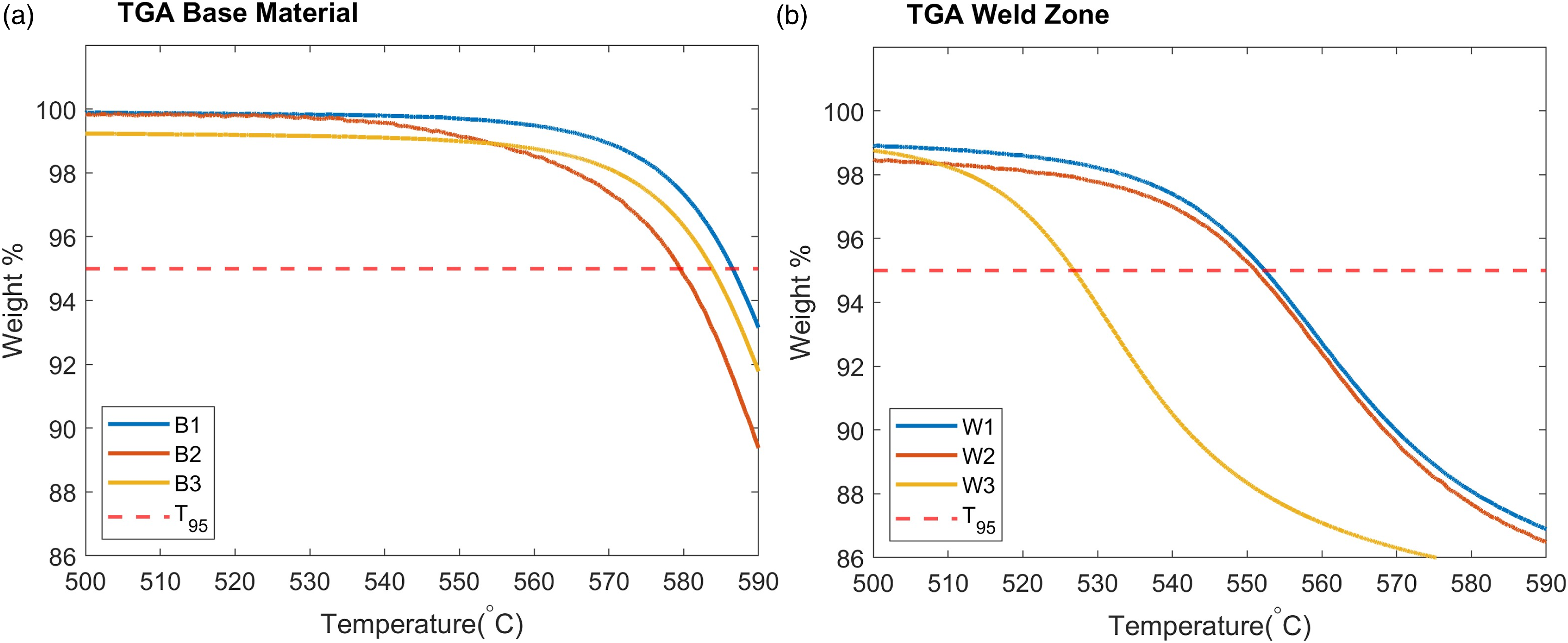
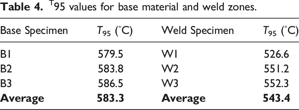
The lower thermal stability in welded specimens is a result of the short fiber length in the weld zone. The addition of carbon fiber into a polymer matrix increases the overall absorption capacity of the composite, and longer fibers allow the composite to withstand greater temperatures since they absorb more heat. 39 Highly localized temperatures around the tool/composite interface may also contribute to slight reduction in thermal stability, but the low thermal conductivity further limits widespread thermal degradation throughout the weld. Confirmation of decreased thermal stability due to overheating of the polymer requires the capability to accurately measure the temperature at the interface between the tool and polymer during welding.
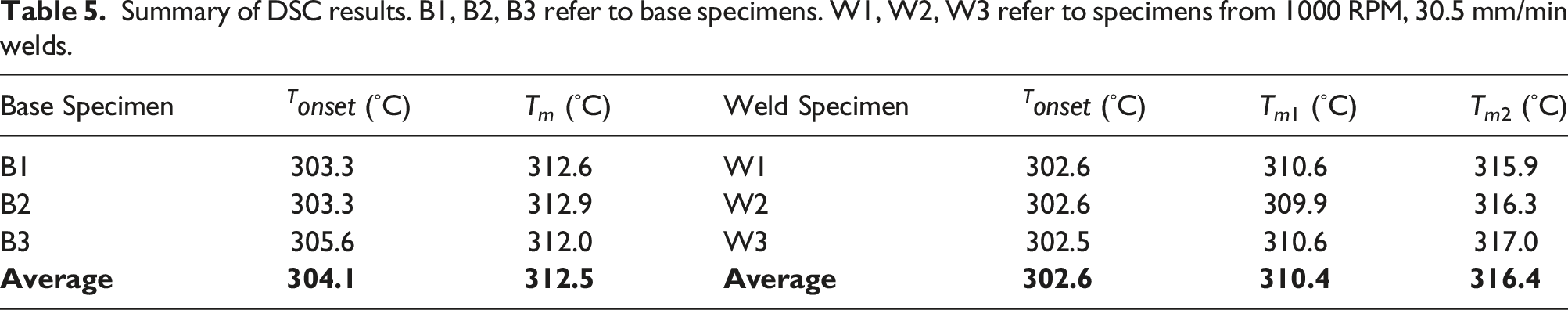
Differential Scanning Calorimetry Figure 14 shows the differential scanning calorimetry (DSC) melting endotherms obtained for specimens while undergoing TGA, as the TA Instruments Q600 SDT performs these measurements simultaneously. Table 5 summarizes the DSC results. Toray reports the melting temperature for the base composite to be 305°C.
32
The onset melt temperatures (Tonset) for both the base material and weld zones are in good agreement with the manufacturer’s reported melting temperature. The average peak melting temperature T
m
for the base laminate material is 312.5°C, reported in Table 5. Specimens cut from weld zones exhibit a broader melting curve with two inflection points indicating two peaks. The double-melting behavior results from reorganization of the crystal structure as the temperature increases.
40
The chopped fibers in the weld zone improve chain mobility and allow for this double-melting behavior. DSC curves for (a) base carbon fiber laminate and (b) weld zones of 1000 RPM, 30.5 mm/min specimens. Endothermic curves point upwards. Summary of DSC results. B1, B2, B3 refer to base specimens. W1, W2, W3 refer to specimens from 1000 RPM, 30.5 mm/min welds.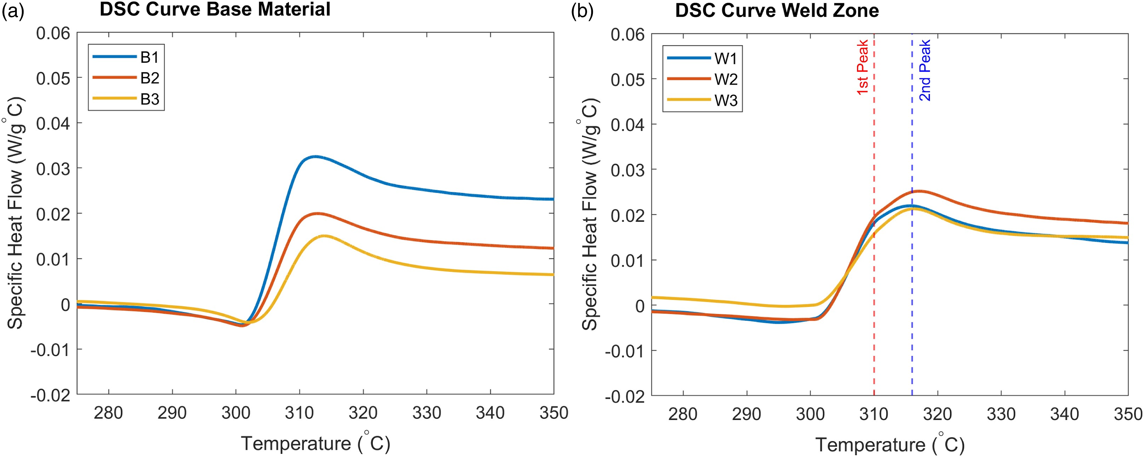
Welder Inputs
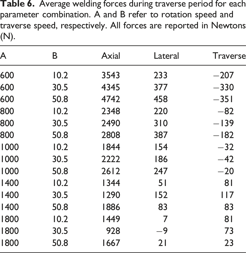
Average welding forces during traverse period for each parameter combination. A and B refer to rotation speed and traverse speed, respectively. All forces are reported in Newtons (N).
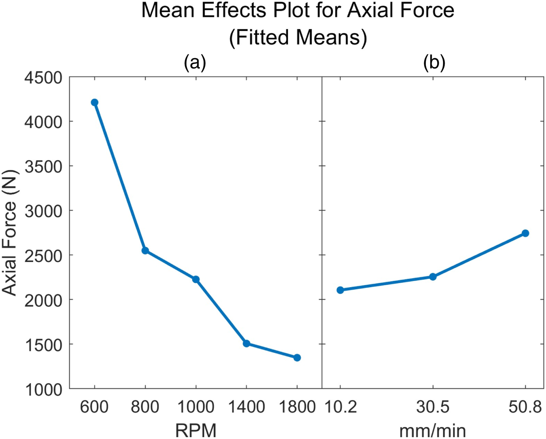
Fitted mean effects for tool rotation speed (a) and traverse speed (b) on axial force.
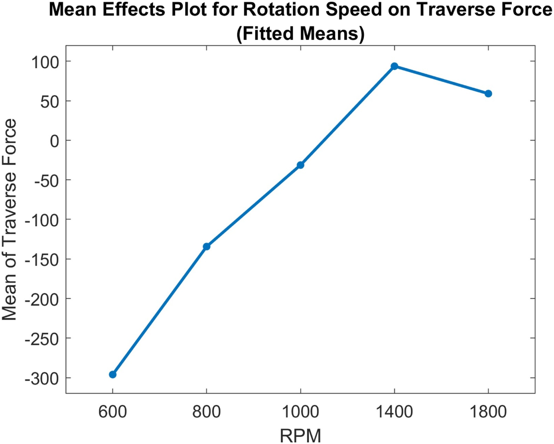
Fitted mean effects for tool rotation speed on traverse force.
Power Consumption Equation (2) calculates the power consumption by the tool during welding:
Discussion
Until now, extensive study pertaining to FSW of CFRTP laminate sheets have yet to be explored. The feasibility and applicability of this process over other joining methods depends on joint strength, processing time, joint configuration, and tooling requirements. Processing of CFRTP inherently has challenges due to its non-homogenous structure. FSW of carbon fiber laminate sheets has complexity due to the disruption of carbon fibers in the weld zone and poor through-sheet thermal conductivity. This study shows promising results with instances of high strength, but also clear indications of improvements needing attention.
Some tool wear was evident throughout the course of the study, shown in Figure 17. Tool wear influence likely has little significance on studied parameter effects contributing to weld strength in this study, as the order of blocked welding replicates were randomized. However, tools in large volume production of CFRTP FSW joints should be constructed of materials with higher abrasion resilience such as A11 tool steel.
24
Worn tool shoulder and pin from carbon fiber abrasion.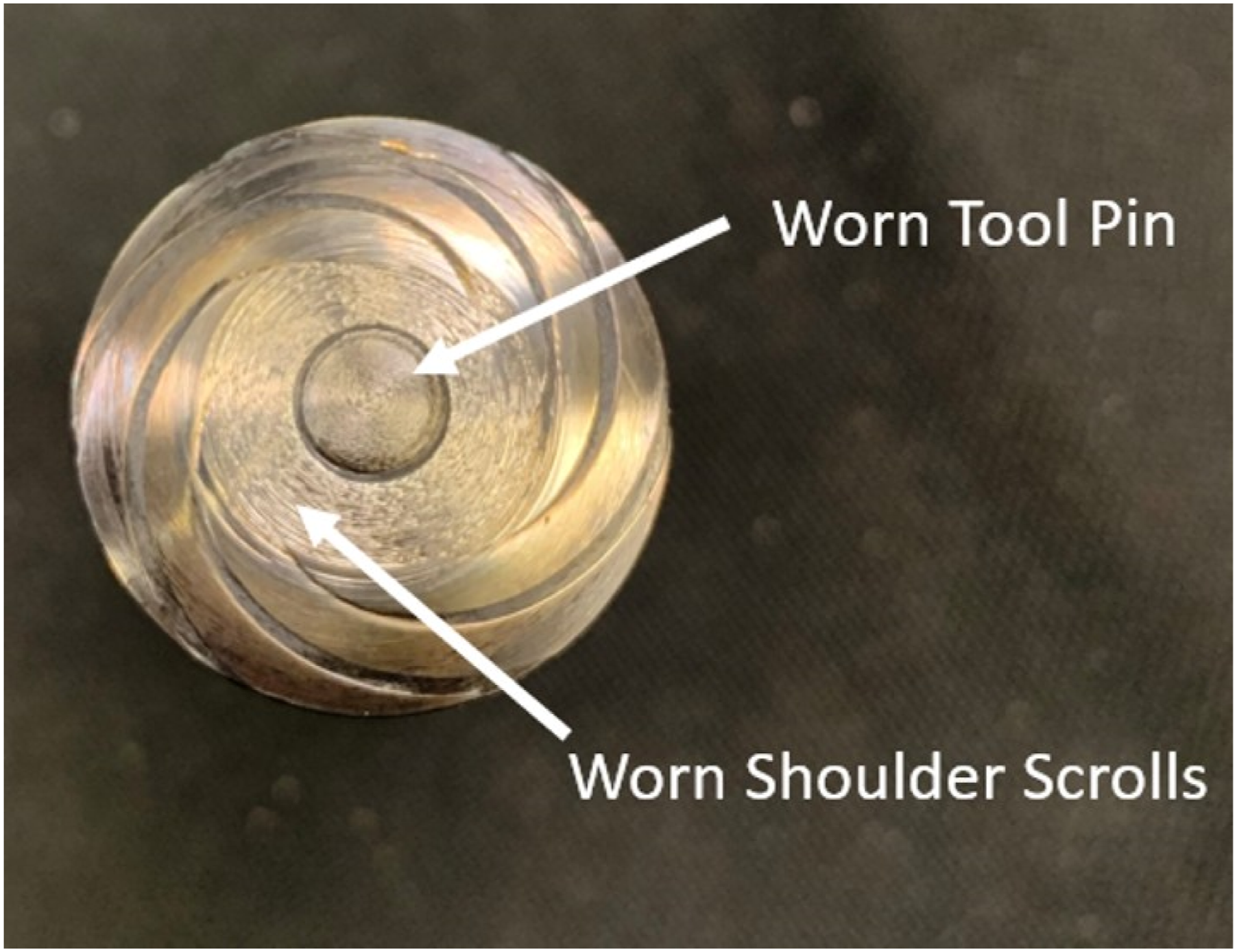
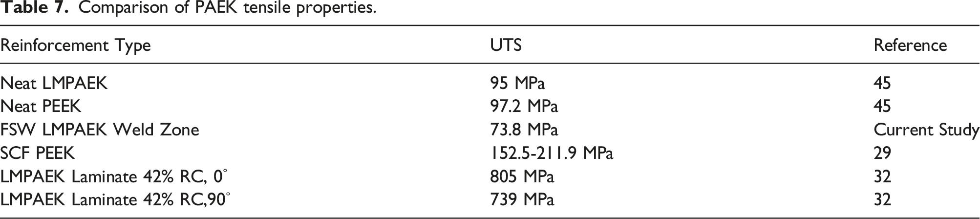
Comparison of PAEK tensile properties.
Though complications persist for carbon fiber laminate FSW, there are several attributes that may qualify it as an attractive process to join CFRTP laminates in the future. Since the fracture mode for thin sheets in CFRTP laminate FSW is purely tensile in the top sheet, structural strength can be further improved by increasing the thickness of the top adjoining sheet. Whether or not the load bearing capacity of friction stir welded laminate sheets scales linearly with top sheet thickness is reserved for future study. The lap shear strength between the weld zone and bottom sheet is also a mechanical feature to consider when increasing the top sheet thickness since excessive thickening of the top sheet may encroach on the lap shear load bearing capacity.
CFRTP laminate FSW has an advantage over ultrasonic welding since it does not require integration of energy directors that makes consistent continuous welds and in-situ monitoring challenging tasks to achieve. 46 Further, FSW does not use consumables such as gas in hot gas welding, and does not leave embedded wires such as those in resistive welding. A drawback to FSW in CFRTP joints is the welding speed. Continuous ultrasonic welders can join CFRTP on the order of several meters per minute, 47 while FSW traverses on the order of several centimeters per minute. However, the simplicity of FSW improves the overall process efficiency when considering material preparation and post-weld processing. 48 Current FSW equipment designed to join metal alloys used in components such as rocket fuel tanks and pressure vessels can be easily adapted to weld newer composite versions of these components since metal and polymeric FSW share the same basic tooling principles. Thus, improvements in future study of continuous CFRTP FSW will make it a viable and competitive process in the manufacture of composite structures.
Conclusions
This work uses FSW to join LMPAEK CFRTP laminate sheets in lap joint configuration. Joining two laminate carbon fiber sheets via FSW has novelty in the field and presents challenges since it requires disruption of the woven fibers in the laminate. A parameter study was conducted to determine the effects of tool rotation speed and traverse speed on weld integrity. The results indicate the following: • Fiber disruption in the weld zone forms distinct zones with variable fiber size and orientation. • Parameters of 1000 RPM rotation speed and 30.5 mm/min traverse speed produce tensile strengths of 73.8 MPa, which is approximately 50% the strength of a comparable short carbon fiber reinforced composite. • Weld porosity appears to have the greatest influence on strength reduction, with failure initiating defects located along the base material/weld zone interface. • Thermal analysis shows slightly reduced thermal stability in the weld zone at high temperatures due to greater polymer mobility for discontinuous fibers with thermal degradation occurring at approximately 40°C cooler temperatures than the base laminate material. • Optimized welding parameters require 2200 N of axial force and 67.4 W of power during traversing periods requiring lower machine requirements than FSW of metal alloys.
Advancements in aerospace technology requires increased used of high-performance materials and solutions to join them that better harness their capabilities in space systems. Though pre-existing welding methods exist to join CFRTP laminates, FSW offers additional versatility and competitive joint strengths to other joining methods.
Footnotes
Declaration of conflicting interests
The author(s) declared no potential conflicts of interest with respect to the research, authorship, and/or publication of this article.
Funding
The author(s) disclosed receipt of the following financial support for the research, authorship, and/or publication of this article: This work was supported by the NASA Tennessee Space Grant Consortium (SFP_300530).