
Abstract
Designing bio-composites for structural applications requires a thorough understanding of their mechanical behavior. In this study, we examined the differences in the tensile strength and drop-weight impact response between polypropylene reinforced with flax fibers and that reinforced with pinewood short fibers, as both fibers differ in composition (cellulose, hemicellulose, and lignin) and length-to-diameter ratio. We found that flax fibers, which have higher cellulose content and are twice as long as pine fibers, increased the stiffness and shock resistance of bio-composite materials. However, pine fibers, which contain more lignin, showed increased material ductility and energy absorption. Impulse excitation, acoustic emission and micro-CT techniques were used to evaluate the post-impact mechanical properties and the contribution of each damage mechanism to the final material failure (tearing). The experimental results were used to validate a model based on finite elements. Our results revealed that the experimental and finite-element analyses were in good agreement.
Keywords
Introduction
Standard thermoplastics reinforced with short natural fibers (SNFTs) are an interesting category of bio-composites with specific mechanical properties that are comparable to those of synthetic fiber composites or engineering thermoplastics such as polyamides (PA6 and PA11). 1 SNFTs are used in several industrial sectors such as the automotive, construction, and packaging industries. Their advantages include their high specific stiffness and strength, low abrasion tendencies, good recyclability, low implementation cost, and, above all, the possibility of manufacturing parts with a single-injection-molded element in complex shapes. Despite these advantages, the use of SNFTs for structural applications remains limited, as reported in the literature.1,2,3,4
The designing and sizing of SNFTs for structural applications require a better understanding of their mechanical behavior as well as detailed analyses to assess the behavior of these materials, their properties, and their failure modes. The importance of a detailed analysis stems from the fact that the mechanical behavior and performance of SNFTs are directly linked with different parameters, such as fiber morphology, chemical composition, and distribution in the bio-composite, the quality of fiber/matrix adhesion, and the bio-composite manufacturing process.5,6,7,8
Tensile properties of polypropylene (PP) composites reinforced with 30 wt % of different natural fibers and the chemical compositions of each fiber.
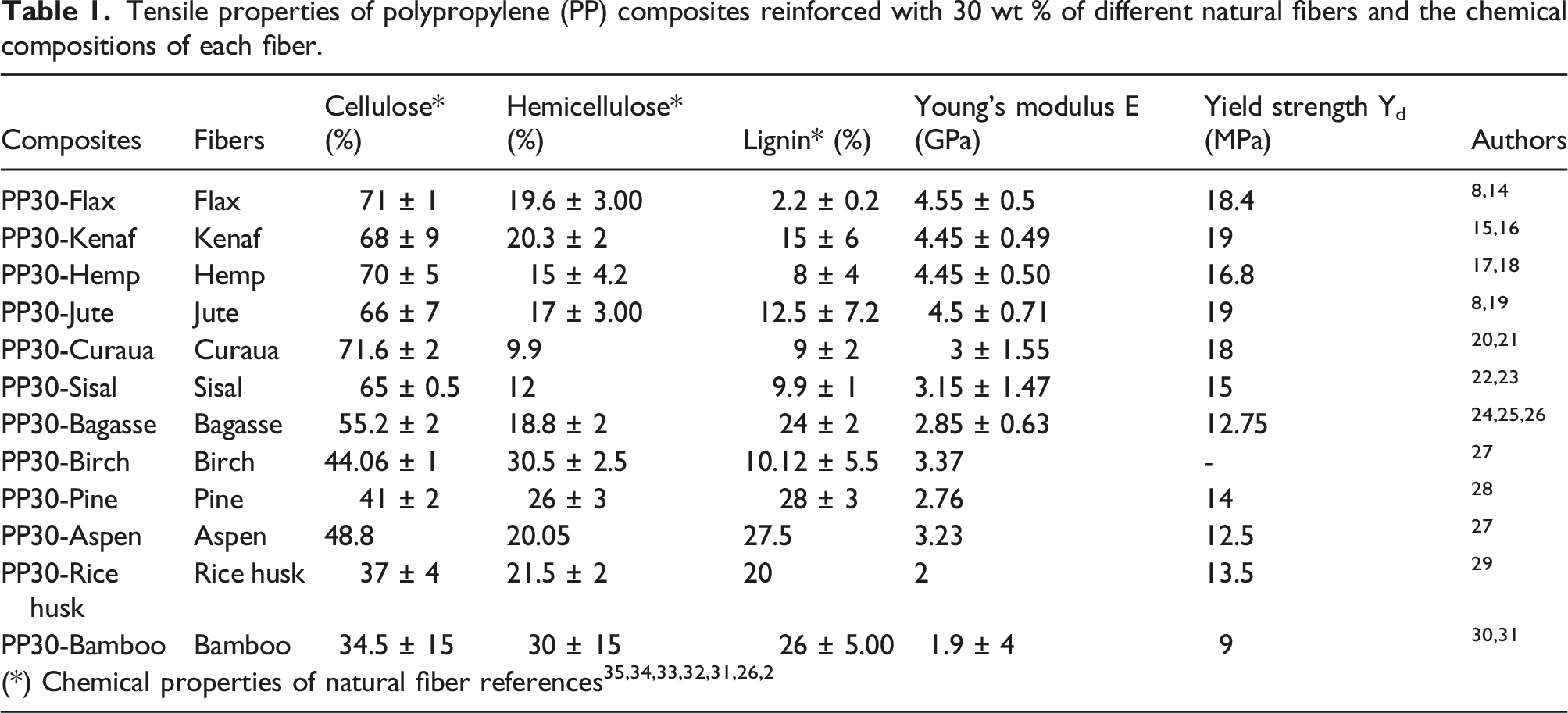
Although the mechanical properties of SNFTs are related to the chemical compositions of the natural fibers, they can also be influenced by other factors such as the manufacturing process and morphology. Tanguy et al.
8
showed that although flax fibers have a higher percentage of cellulose than jute fibers, PP reinforced with short jute fibers has better mechanical properties than that reinforced with short flax fibers. This result was attributed to the injection-molding process. They explained that more fibers in the PP-Jute samples, than those in the
As we can see in Table 1, several authors have characterized natural fiber composites in terms of their quasi-static mechanical properties, mostly using tensile and bending tests. In contrast, few studies have investigated the drop-weight impact behavior of SNFTs. In mechanical design, the effect of impact damage on the integrity and strength of the materials throughout the life of the object must be considered. Studies on the sensitivity of SNFTs to impact damage and on their modes of failure provide important data for designing applications that require good impact resistance, such as gears, exterior automotive parts, and lightweight drones. However, the lack of data on the durability of SNFTs and their impact resistance is a major hurdle in their adoption in structural applications. Puech et al. 37 analyzed the drop-weight impact behavior of PP reinforced with 12% hemp fibers (PP-H) both experimentally and numerically. Using a high-velocity camera, they observed the behavior of the bio-composite through all the impact damage stages. The damage began after an elastic phase, typically in the matrix, and appeared as permanent deformations, mainly in the form of indentations and localized discontinuities. This step was followed by a nonlinear phase, which marked the progression of crack formation until perforation. Bledski et al. 38 studied the effect of the manufacturing process on the drop-weight impact behavior of wood-fiber-reinforced PP composites. Better results can be obtained by injection molding than by heated compression molding. Recently, Koffi et al. 39 investigated the influence of fiber content on the impact behavior of birch short-fiber-reinforced polyethylene. They found that the absorbed energy and deformation at failure decreased as the fiber content increased. However, most of the studies on the impact behavior of SNFTs were of the Izod or Charpy uniaxial type, which neither simulated nor reflected the actual impact conditions of the part being tested. In addition, no study considered the effect of chemical composition (cellulose and lignin content) on SNFT impact behavior.
This study examines the tensile strength and drop-weight response of polypropylene reinforced with flax and pinewood short fibers, which differ in composition (cellulose, hemicellulose, and lignin). The aim is to determine and evaluate the influence of lignin content on the mechanical properties, and especially the damage mechanisms, and impact behavior of short natural fiber-reinforced thermoplastic (SNFT). To our knowledge, lignin content in composite has never been explicitly studied to evaluate their damages and impact on low-velocity impact responses of short fibers composite materials. Initially, during tensile tests, we use the acoustic emission method to investigate the progression of various damage mechanisms that ultimately result in the fracture of the test specimen. The goal is to obtain a distinctive acoustic signature of mechanisms of damage that can differentiate the levels of damage in the tested material depending on the lignin content. Secondly, we estimate the drop-weight impact behavior of PP bio-composites reinforced with either flax or pine short fibers for different impact energy and evaluated the influence of the chemical properties and morphologies of these fibers on the damage threshold using a retting technique and X-ray micro-computed tomography (μCT). A link has been established between the impact performances of materials and their lignin and cellulose content. Finally, the impulse excitation technique was used to evaluate post-impact mechanical properties. Experimental results were used to validate a model based on finite element analysis, which might become a useful tool for predicting the impact resistance of natural-short-fiber-reinforced thermoplastic bio-composites.
Materials and methods
Production process of the test samples
Virgin polypropylene (PP) with a melt flow index of 17 g/10 min and density of 0.989 g/cm³ provided by NOVA Chemicals Inc., and polypropylene bio-composite grains reinforced with 30% short flax fiber (PP30-F) or 30% short pine fiber (PP30-P) purchased from Rhetech, MI, USA, were used in this study. Although this company refused to provide us with the characteristics of the natural fibers, it is known that natural fibers are mainly composed of cellulose, hemicellulose, and lignin. According to Table 1, the chemical composition of flax fibers is as follows: 71 ± 1% cellulose, 19.6 ± 3.00% hemicelluloses, and 2.2 ± 0.2% lignin, whereas pine wood fiber contains 41 ± 2% cellulose, 26 ± 3% hemicelluloses, and 28 ± 3% lignin. This suggests that pine fibers are high in lignin, whereas the low-lignin flax fibers have a very high percentage of cellulose and hemicellulose fibers.
A 100-ton capacity Zerus 900 press (Zeres series, model ZE900/210; Zhafir Plastics Machinery, Ebermannsdorf, Germany) was used to inject the composite. The test sample dimensions were in accordance with ASTM D638 40 and ASTM D5628 41 for tensile and impact tests, respectively, and the injection was carried out at a temperature of 180°C. The granules were dried in an oven at a temperature 80°C for 2 h before being injected to eliminate moisture from the fibers and thus reduce or even avoid microvoids in the samples. Figure 1 shows the micro-computed tomography analysis of the PP-flax fiber test sample. The white spots (Figure 1(c)) indicate the presence of pores. The geometrical dimensions of the fibers (Table 2) and the percentage of pores in the material (less than 5%) were derived from this imaging. a) Impact test sample PP30-F; b) X-ray microtomography; c) three-dimensional reconstructed micro--computed tomography scan showing the distribution of voids in the specimen. Geometry of the flax and pinewood fibers.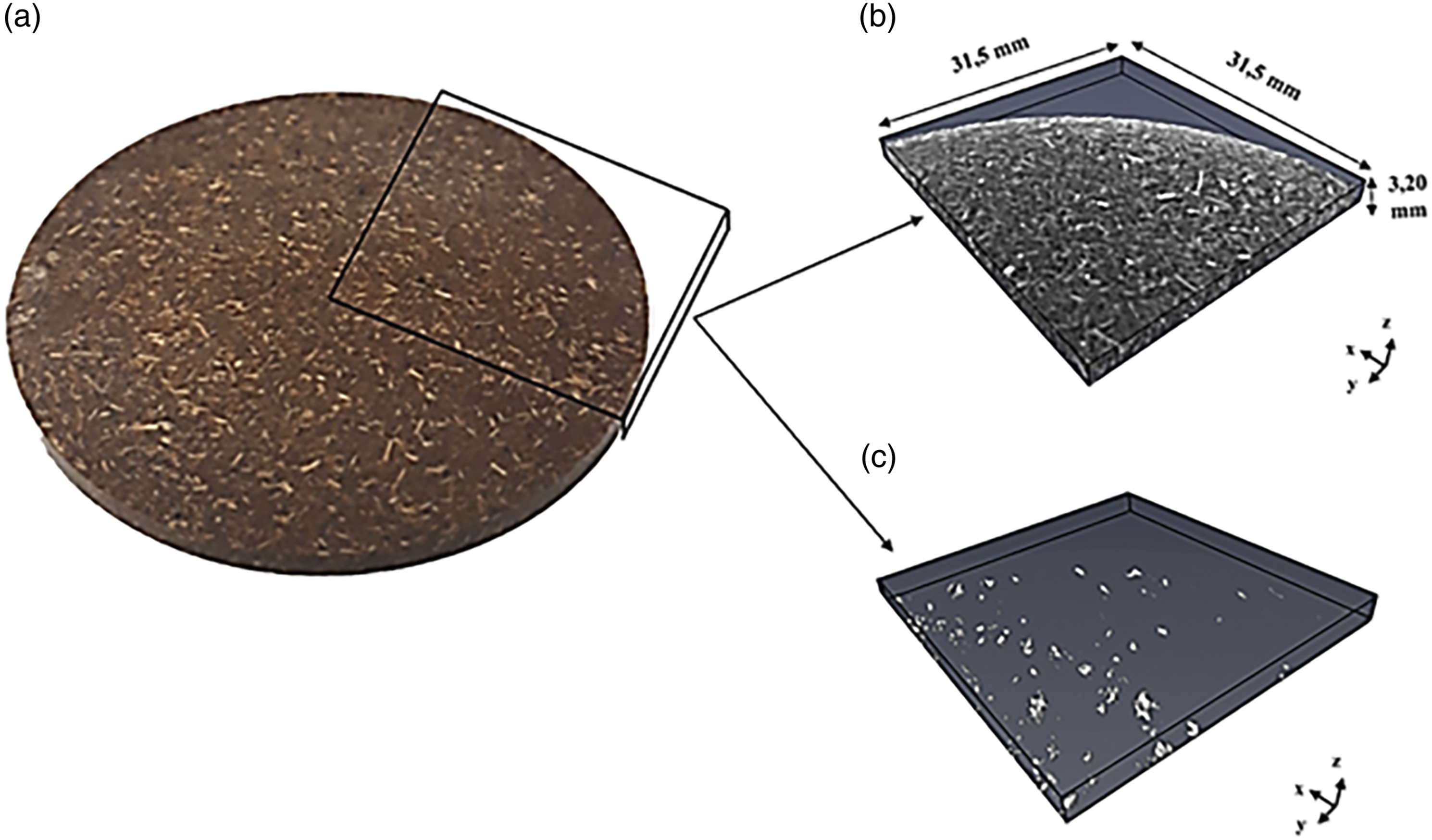
Tensile test
Tensile tests were conducted using an Instron electromechanical device (model LM-U150) fitted with a 10 kN load cell, in accordance with ASTM standard D 638. 40 Three samples were tested for each experimental condition. The deformation and displacement were measured using a digital image correlation system (LaVision Inc., Göttingen, Germany).
Acoustic emissions were measured using an apparatus from the Physical Acoustics Corporation (Princton Jct, NJ, USA) with two Micro-80 large-band sensors (100–1000 kHz). The timing parameters were PDT, 40 μs; HDT, 80 μs; and HLT, 200 μs. The recorded signals were classified according to amplitude, number of hits, duration, and frequency. Based on the unsupervised neural network technique, each group of acoustic events is attributed to a damage mechanism.
Drop-weight impact test
Hemispherical 20-mm impactors were used to deliver the impact on an Instron CEAST 9350 device fitted with a 22 kN load cell. The impact energy ranged from 1.6 J to 5 J for different impactor masses. An antibounce system was used to ensure a single impact on the test specimen. The tests were conducted in accordance with the ASTM standard D5628. 41 Three samples were tested for each experimental condition.
Damage analysis of test samples
X-ray micro-computed tomography
An EasyTom 130 apparatus was used at 130 kV and 300 mA to obtain micro-CT X-ray scans of the samples after the impact. The scanner was equipped with a sealed micro-focus X-ray tube with a 3-µm spot size and a high-resolution flat-screen detector with 1920 × 1536 pixels, each 127 µm in diameter. The maximum resolution under the conditions used in this study was approximately 18 µm. These measurements helped us to distinguish between the fiber, matrix, and pores (empty space) of the material, as well as appraise the type and extent of damage sustained as a function of impact energy.
Post-test retting of material coupons
Visual examination of the macroscopic cracks due to impact was facilitated by spraying a colored liquid onto the cracked test specimen surfaces. After allowing the liquid to penetrate for 20 min, the excess penetrant was removed by applying a blotter to reveal the presence of discontinuities.
Use of coordinate-measuring machines
The cross-sectional profile of the unperforated impact test samples was recorded using a coordinate-measuring machine BH305 (Mitutoyo). This provides the depth and diameter of the imprint left by the impactor. The resolution of the device was 0.0001 mm. The profiles were measured 1 month after the impact test to allow the samples to recover from the viscoelastic deformation.
Impulse excitation
To calculate Young’s modulus of each post-impact test coupon, the fundamental resonance frequency in the flexion and twisting modes was measured using an acoustic impulse excitation system (IMCE, Belgium). Elastic properties, such as Young’s modulus and Poisson coefficient, can be calculated from the frequencies in accordance with ASTM standard E1876. 42 This rapid and low-cost technique allows the measurement of the stiffness of the material, both before and after damage has been sustained. 43
Numerical analysis
The finite element model developed to predict material behavior is illustrated in Figure 2. An explicit algorithm for the simulation was derived using the LS-DYNA software. An elastoplastic model of type MAT24 was used with T-shell-type elements to define the mechanical behavior of the SNFTs.
44
The impactor was meshed with 6180 tetrahedral-shaped solid elements and a sample-holding clamp with 11,640 cubic solid elements. The automatic surface-to-surface contact algorithm was used to define the element-by-element contact between the target and impactor, and between the target and sample clamps. Non-perforating and perforating impact energies of 2 J and 5 J, respectively, were considered. For greater stability in the calculation of the explicit scheme, the Friedrich-Levy condition
44
was used, with a time step Illustration of the adopted geometrical model, the impactor tip, boundary conditions, and finite element mesh.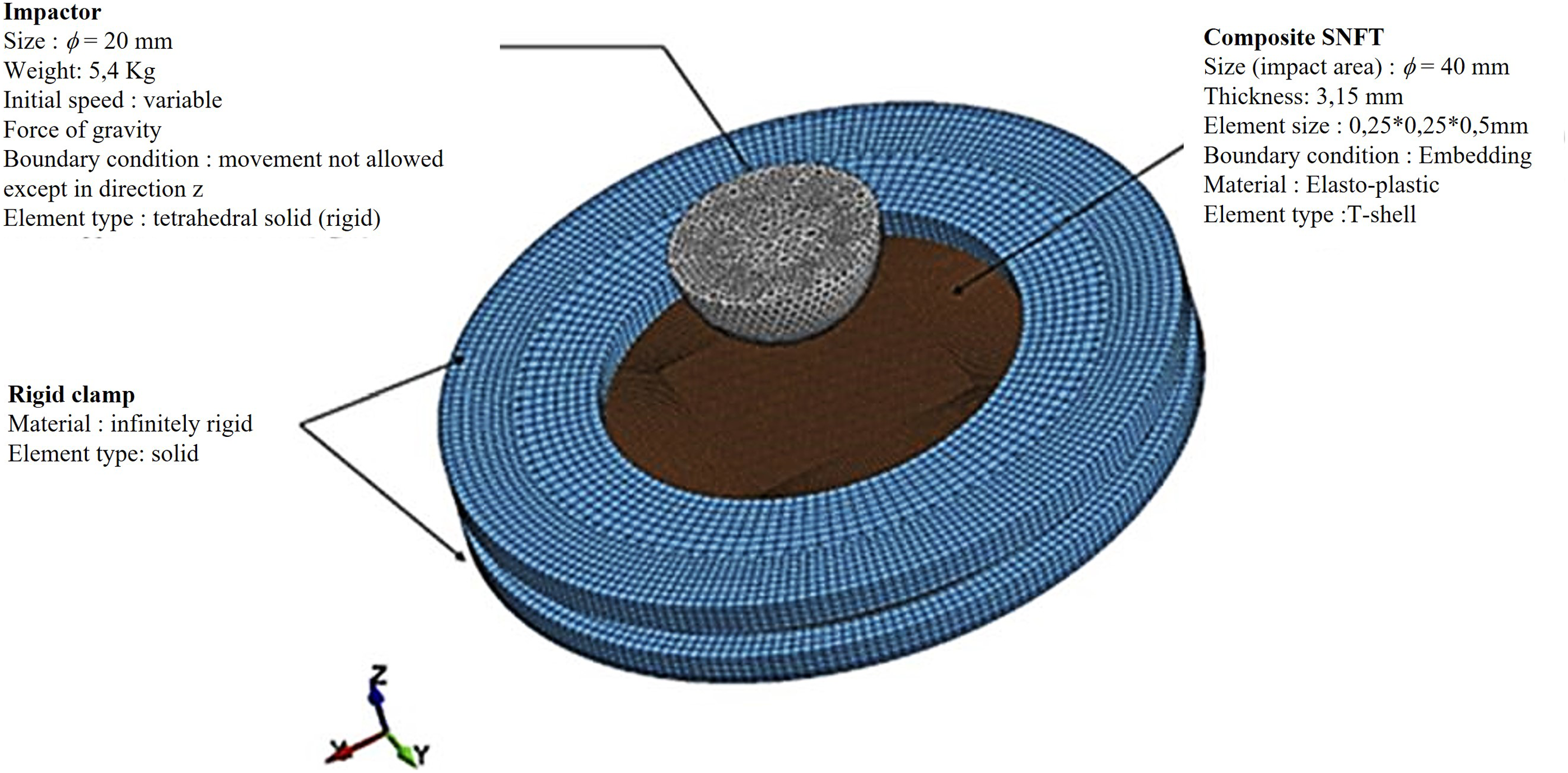
Results and discussion
Tensile tests
The stress-strain curves obtained from the tensile tests of the three materials are shown in Figure 3. The response features linear and non-linear portions. The flax-fiber-composite material had higher strength than the pinewood-fiber-composite, but showed less deformation at the breaking point. Therefore, the ductility of the pinewood-PP composite was greater than that in the flax-fiber composite. Only a part of the pure PP curves is shown here because the plastic deformation exceeded the dimensional limits of the tensile machine used in this study. Stress-strain curve for the pure PP, PP30-F, and PP30-P composites.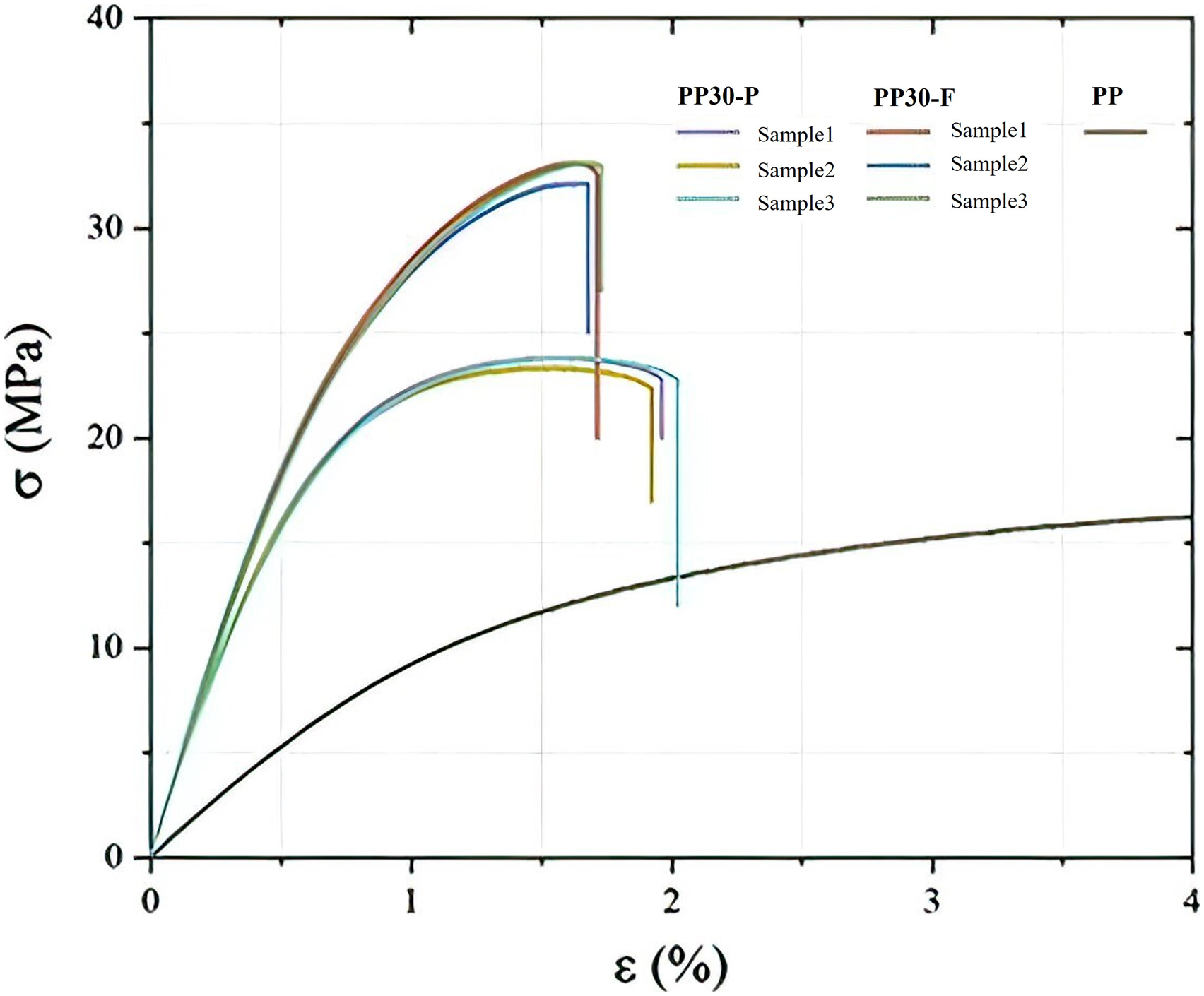
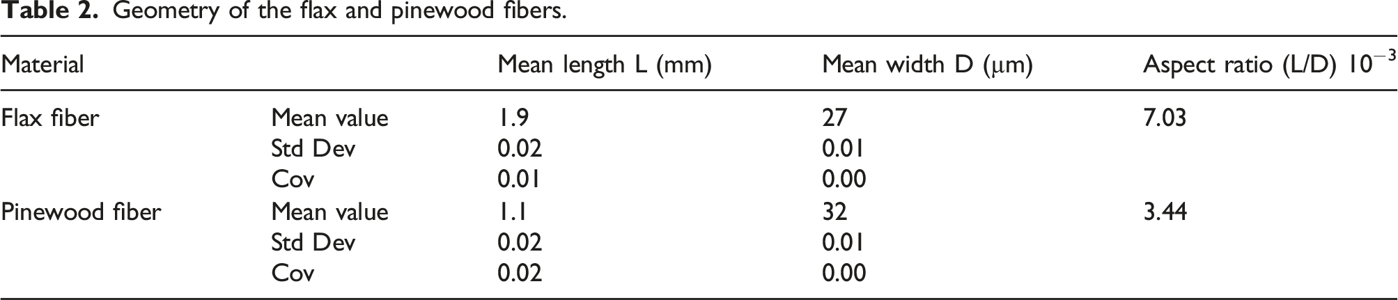
These results suggest that fibers with higher cellulose and hemicellulose content (flax) confer greater strength and stiffness to the PP composite material. This type of natural fiber increases composite strength and stiffness. 9 Fibers containing more lignin improve the material’s ductility, which is consistent with the greater plastic deformation observed at failure of the pinewood-PP composite. 9 The fiber length-to-diameter ratio could also contribute to the mechanical properties of the SNFTs as there exists a two-fold difference between the ratios of the flax and pinewood fibers (Table 2). A high ratio improves the fiber-matrix adhesion and, thus, the mechanical properties of the composite material. 45
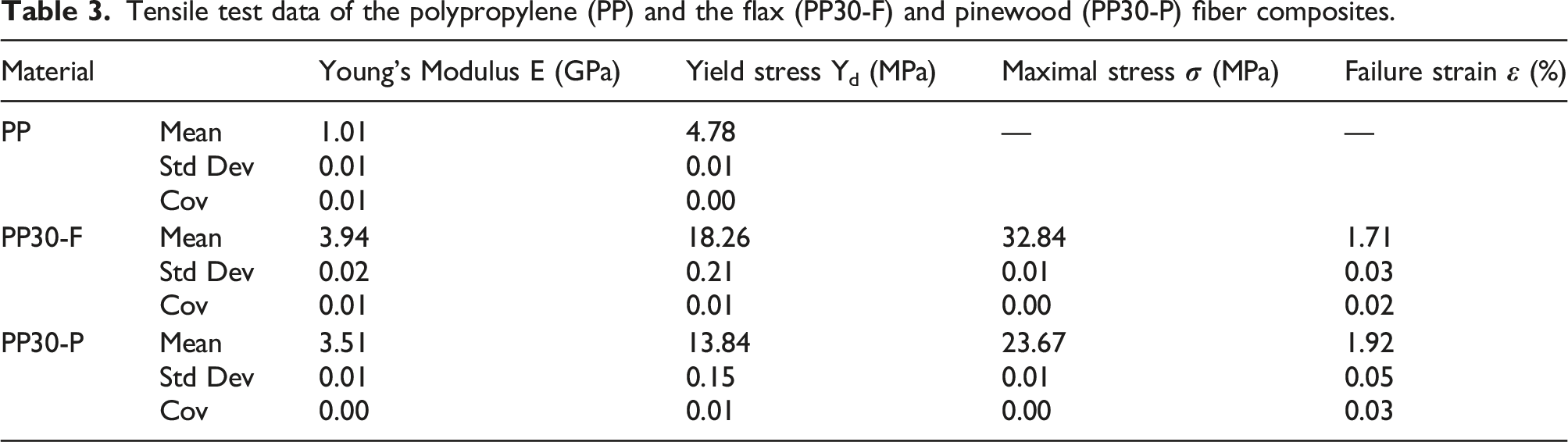
Tensile test data of the polypropylene (PP) and the flax (PP30-F) and pinewood (PP30-P) fiber composites.
Using k-means clustering, we identified the acoustic signature of the four mechanisms of damage that occurred during the tensile test (Figures 4(a) and 5(a)), viz. matrix micro-fissures, matrix internal friction, fiber-matrix decohesion, and fiber-matrix friction.46,47 These mechanisms overlap, each contributing to the final material failure, as shown in the bar diagrams in Figures 4(c) and 5(c). Each contribution was calculated as the damage index D: a) Typical stress/strain curves (black) and acoustic energy burst amplitude with damage mode shown versus elongation in PP30-F composite material test coupons; b) Fractured face of specimens of the PP30-F composite; c) Contribution of the damage mechanisms to the final fracture of the PP30-F samples. a) Typical stress/strain curves (black) and acoustic energy burst amplitude with damage mode shown versus elongation in PP30-P composite material test coupons; b) Fractured face of specimens of PP30-P composite; c) Contribution of the damage mechanisms to the final fracture of the PP30P samples.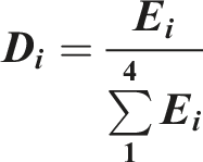
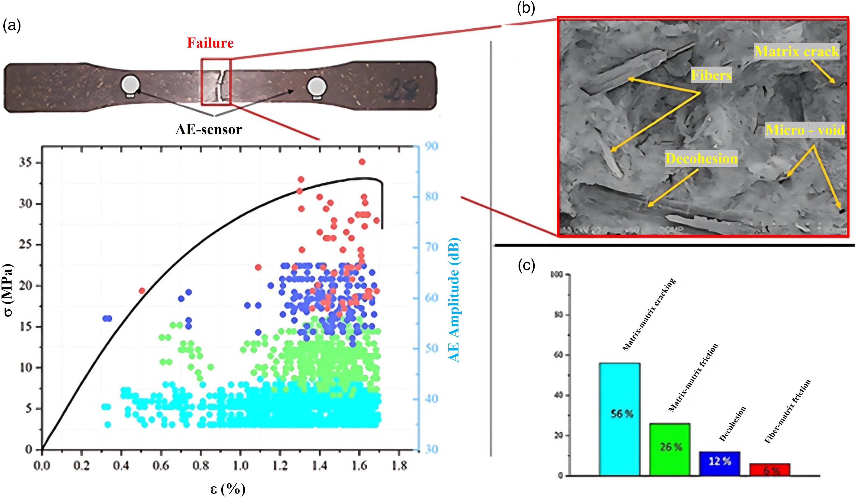
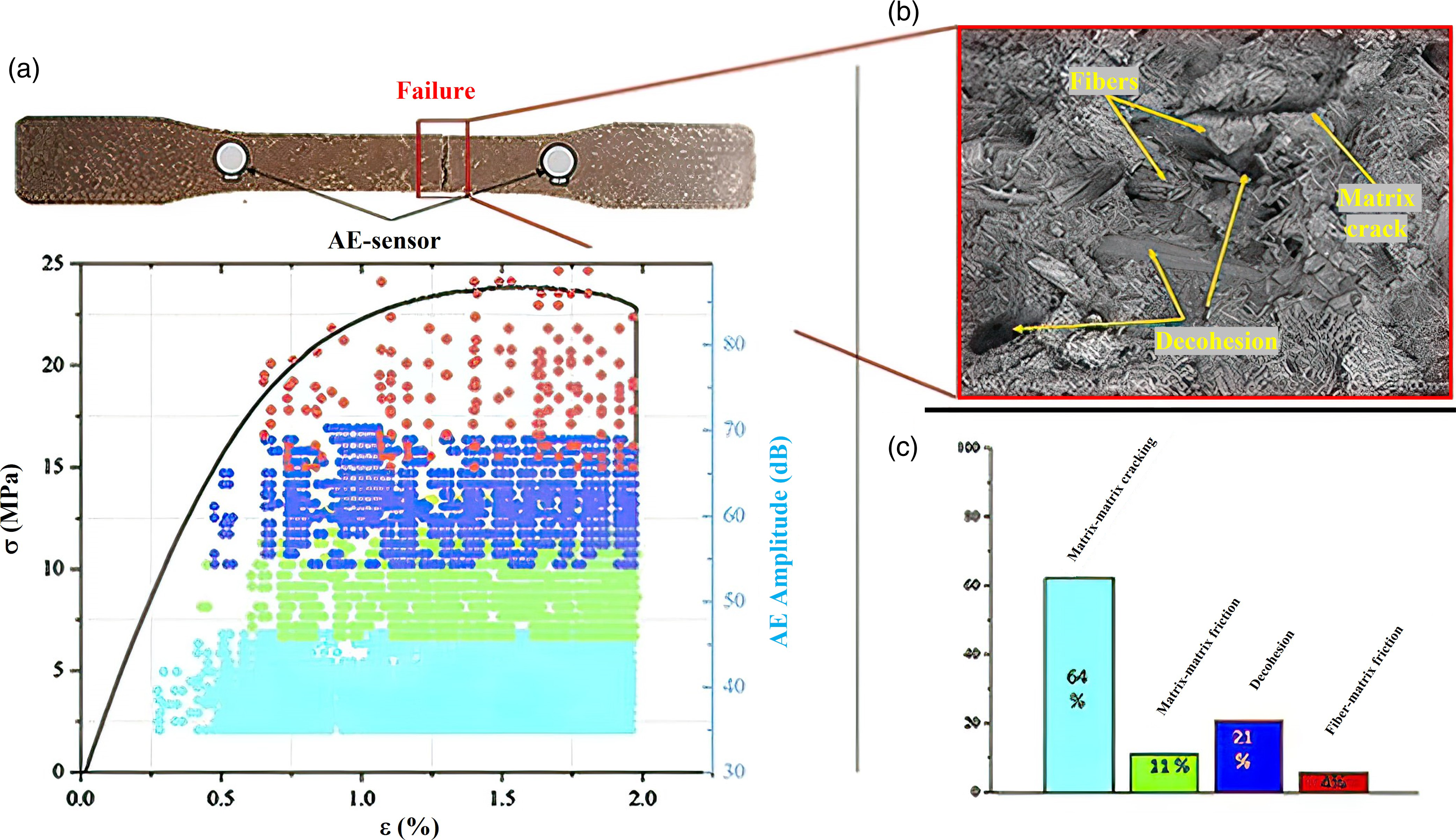
It is clear that matrix microfissures are the dominant type of damage, contributing 56% and 64% for flax and pinewood fibers, respectively. The other damage modes contributed to the damage index as follows: fiber-matrix decohesion, matrix internal friction, and fiber-matrix friction was 12%, 26%, and 6%, respectively, for the flax-fiber composite, and 21%, 11%, and 4%, respectively, for the pinewood-fiber composite. However, in the case of flax fibers, the less dominant mechanisms all begin to appear once the test is well underway at 1.2% elongation. For pinewood fibers, this occurred at 0.5% elongation at the beginning of the plastic phase. Lignin is a hydrophobic substance 8 that adheres more easily to PP and increases the quality of the matrix-fiber interface. Thus, although better fiber-matrix adhesion was expected from pinewood-fiber composites, they occurred instead in the flax-fiber composites. With nearly zero lignin content and a less hydrophobic surface in comparison to that in pinewood fibers, the better result for flax fibers may be explained by a higher length-to-width ratio and stiffer individual fibers. 48 These results show increased fiber-matrix adhesion and delayed onset of decohesion-type damage until the final quarter of the tensile curve. Finally, the better affinity of pinewood-fiber lignin was overcome by the better aspect ratio and intrinsic stiffness of the flax fiber. Thus, the results for the two proposed fibers are the result of a competition between chemical affinity and physical considerations. To corroborate the results obtained by AE analysis, the fractures were analyzed by scanning electron microscopy (SEM). Figures 4(a) and 5(b) show the fractured faces of the unaged PP30-F and PP30-P specimens. Overall, all the mechanisms detected by the AE analysis can be visualized. However, as demonstrated by the AE analysis, a high amount of fiber decohesion can be visualized in PP30-P rather than in PP30-F.
Impact tests
Neither composite material was perforated before the impact energy reached at least 4 J. However, both materials were perforated at 5 J. The contact force and energy absorbed as a function of displacement at 5 J are shown in Figure 6. The behavior of the material appeared to follow four phases. The first was the linear phase—where no loss of strength is apparent and little energy is absorbed—which corresponded with the elastic behavior. At the beginning of the second phase, the strength decreased slightly, and the slope of the displacement force curve changed, thereby indicating the limit of elastic behavior and the onset of damage to the material, as confirmed by the change in the slope of the energy absorption curve. These changes corresponded to the propagation of microfissures within the test specimen during impact. This can only reduce the stiffness and resistance of the material. At the end of this phase, the strength was at its maximum. The third phase began with a significant loss of the measured strength and a decrease in the slope of the energy curve, indicating the formation of cracks in the material.
37
The strength then oscillated around a constant value until a second drop occurred, indicating that the cracks had reached the edges of the sample holding clamp, marking the end of this phase. Absorbed energy beyond this point was the result of perforation (final phase). The maximum energies absorptions were 3.86 J for the flax-fiber and 4.21 J for the pinewood-fiber composites. Beyond the perforation point, the strength decreased slowly because of the slipping of the impactor through the penetrated sample and the dissipation of energy by friction. A high-velocity camera recorded the same phases as those observed in a previous study.
37
Load (left vertical axis) and energy absorption (right vertical axis) versus displacement, (a) polypropylene (PP) with flax fiber; (b) PP with pinewood fiber.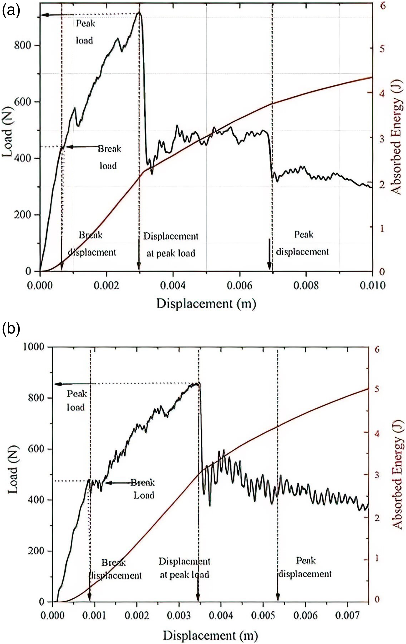
Typical load curves as functions of time and displacement for the different impact energies used in this study are shown in Figure 7. Two types of behaviors emerged as a function of energy. At 1.6 and 2 Joules, the irreversible displacement remained low, and only a few small drops in the contact load were observed. This could be associated with the initiation and propagation of fissures, which did not affect the strength of the composite materials. Starting at 3 J, permanent deformations became apparent, and the drops in the contact strength were more significant. This revealed the appearance and propagation of larger cracks, which decreased the strength of the material. No such damage was observed in pure PP, with only a non-significant permanent deformation. Load over time (left) and displacement (right) of the tested polypropylene (PP) materials: (a and b) composite PP30-F, (c and d) composite PP30-P, and (e and f) pure PP.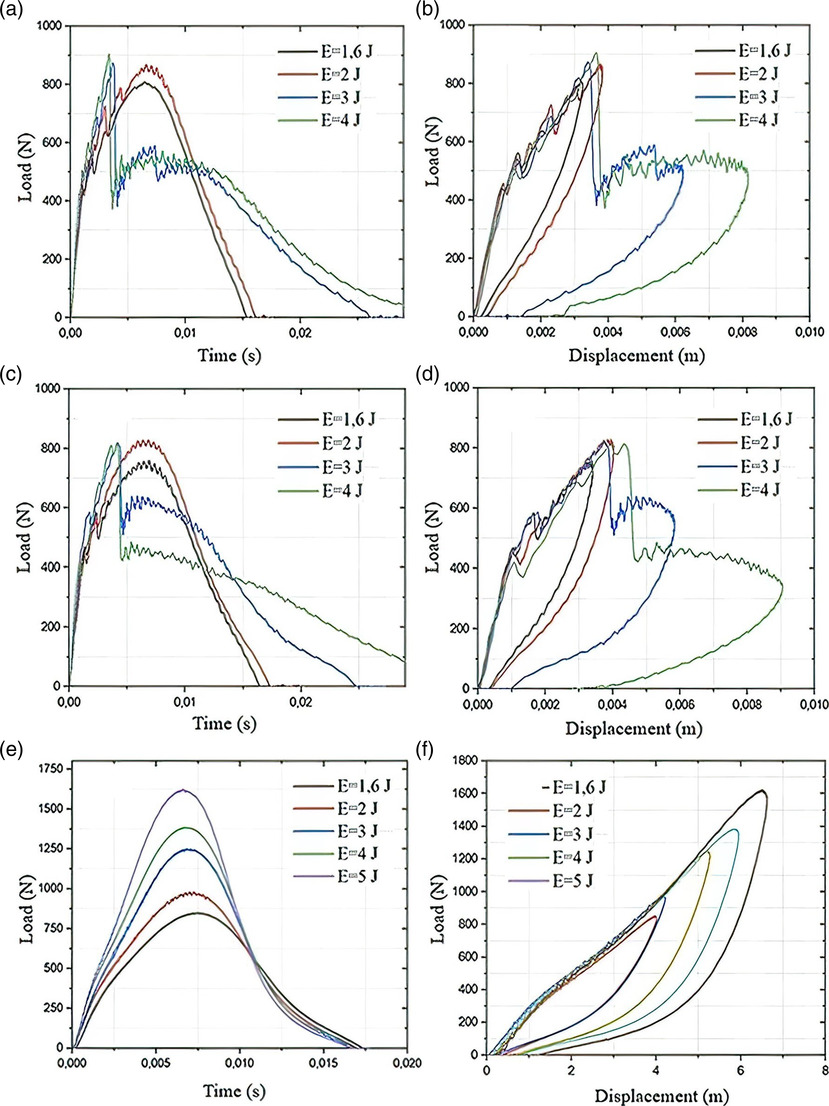
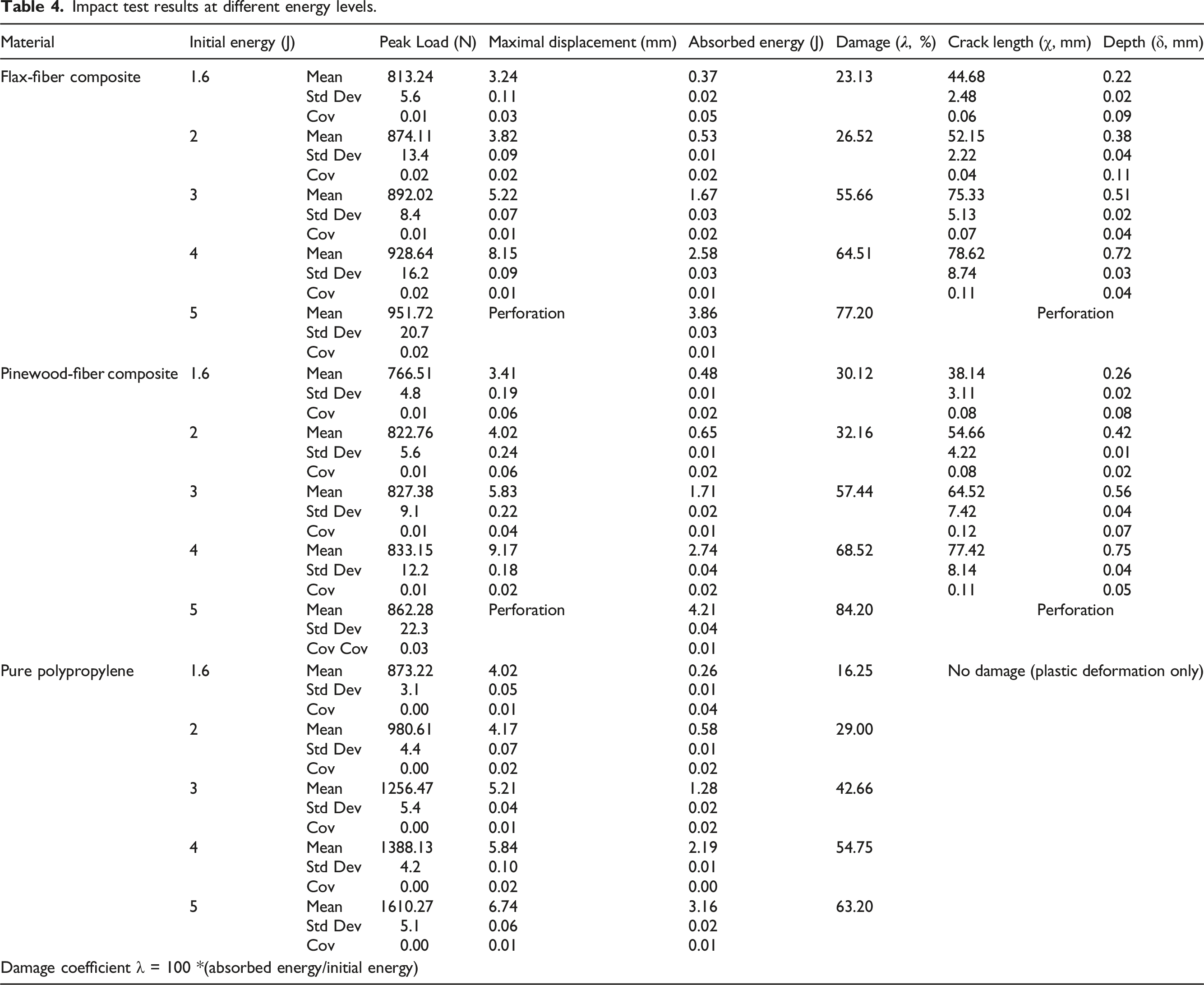
Impact test results at different energy levels.
Analysis of damage sustained
The test samples after retting are shown in Figure 8. Cracks were visible at the center of the specimens. The algebraic sum of crack lengths (χ, Table 4) in all directions was measured using image analysis. In all the samples examined, the total crack length and size of the damaged zone were proportional to the impact energy to which the specimen was subjected. Visible damage revealed by retting the polypropylene composite test specimens (PP30-F and PP30-P).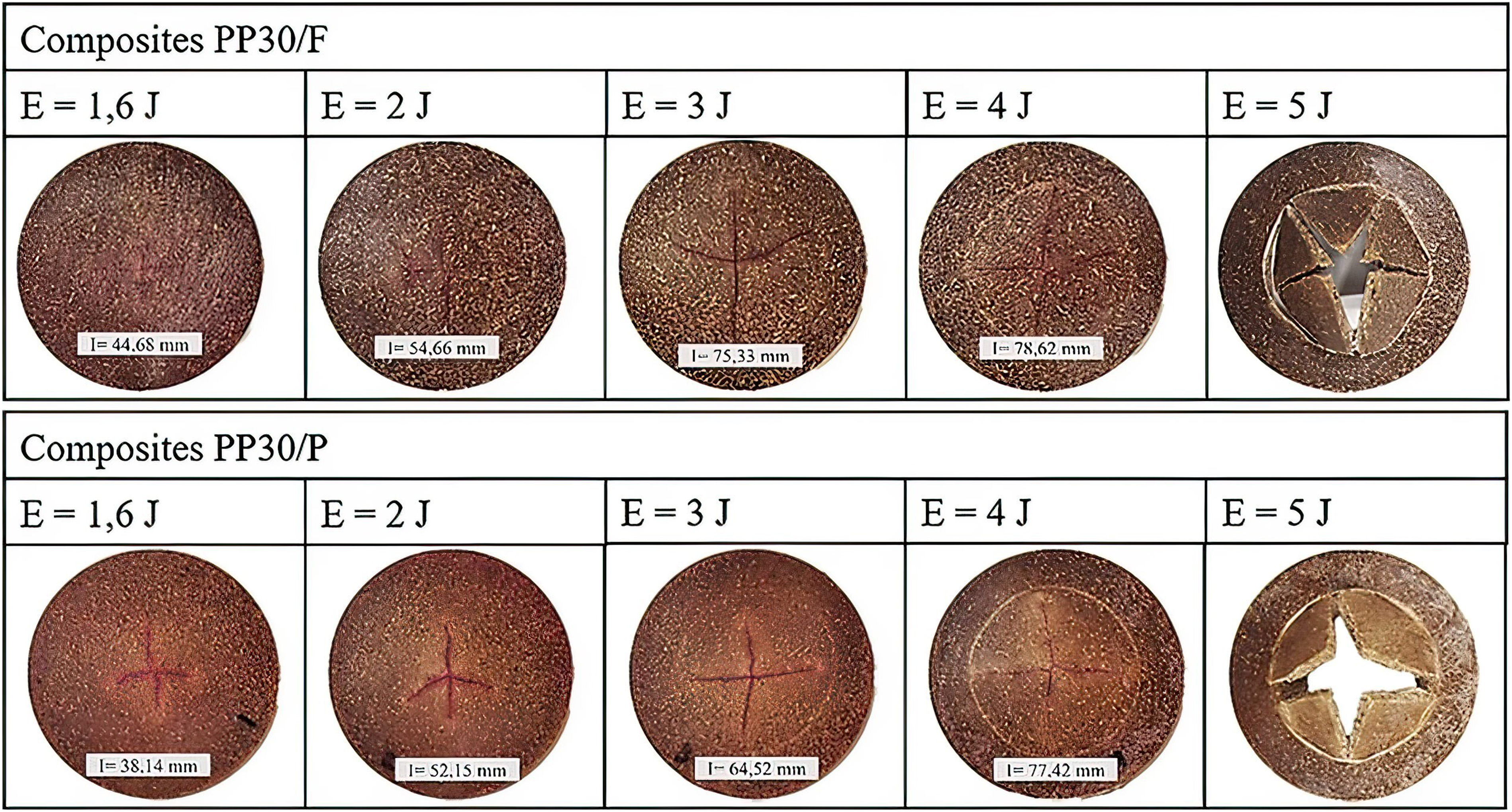
The depth of the damage inflicted at different impact energies, measured using a Mitotoyo-type three-dimensional coordinate-measuring machine (BH305), was compared with a reference (zero deformation) far from the damaged zone (Figure 9). It should be noted that the maximal permanent displacement was recorded at the center of the specimen (depth δ, Table 4). At a given impact energy, the pinewood-fiber composite had an overall greater permanent formation as this material was more ductile. However, the cracks were larger in the flax-fiber composite as this material was more rigid. Depression depth in PP30- F and PP30-P composites.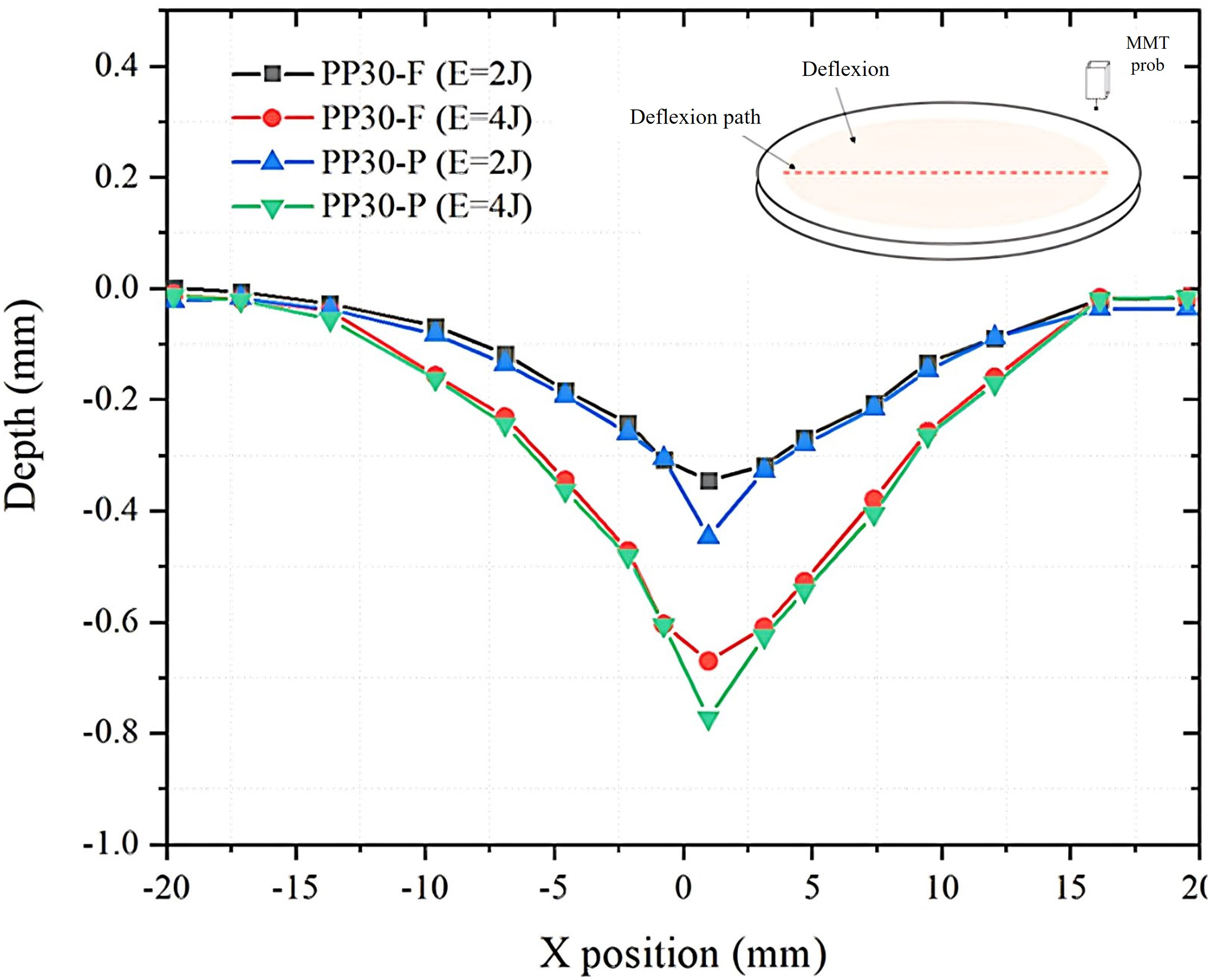
Micro-CT analysis images of the crack size and indentation depth are shown in Figure 10 for the 2-J impact tests and in Figure 11 for the 3-J impact tests. These results indicate that cracks occurred primarily at the center of the test specimen. Their lengths were 51.23 mm and 77.42 mm in flax-fiber material and 50.48 mm and 66.23 mm in pinewood-fiber material. In the same order, the corresponding indentations were 0.41 mm, 0.57 mm, 0.41 mm, and 0.59 mm. The tomography results were similar to those obtained by retting and coordinate measurements. Micro-CT images of impact damage at 2 J to polypropylene composite reinforced with Micro-CT images of impact damage at 3 J to polypropylene composite reinforced with 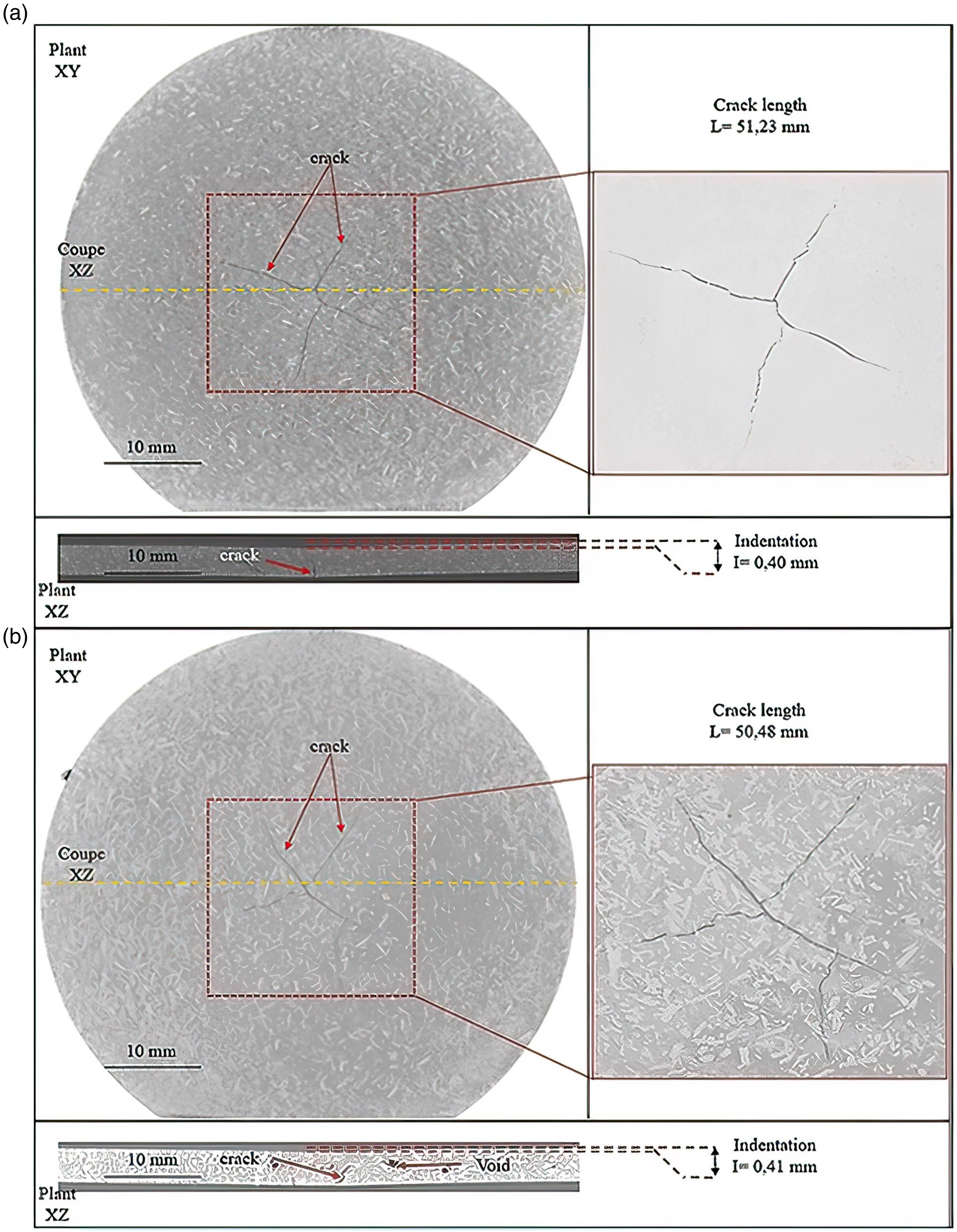
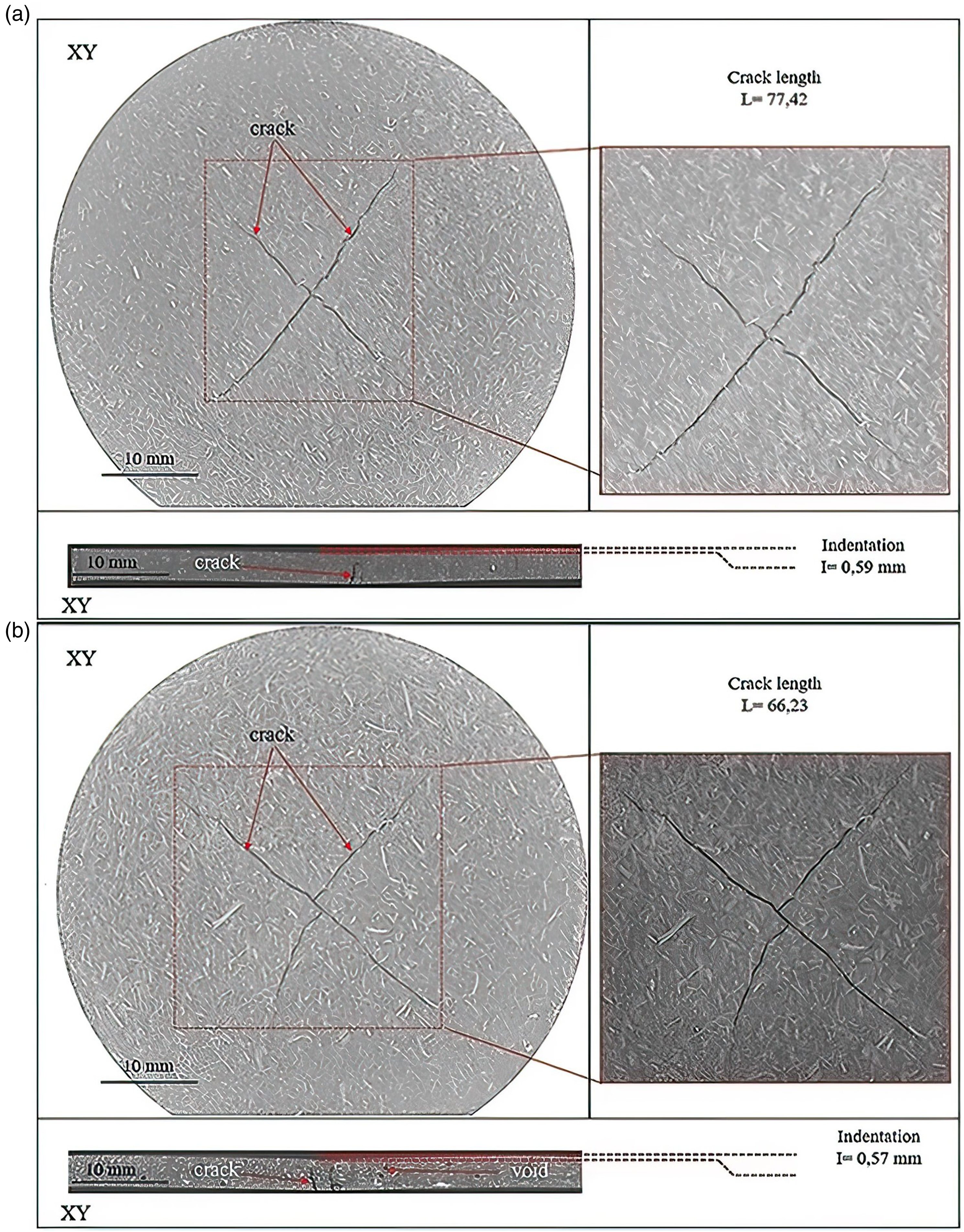
Figure 12 presents the damage to the bio-composites in terms of permanent displacement and the depth of the cracks inside the samples. The results were obtained from the X-ray tomography measurements. According to the figures, PP30-F presents more cracks but less permanent displacement. This suggests that PP30-F is more brittle and rigid, as confirmed previously (Section 3.3). Damages of bio-composites (permanent displacement and cracks depth), 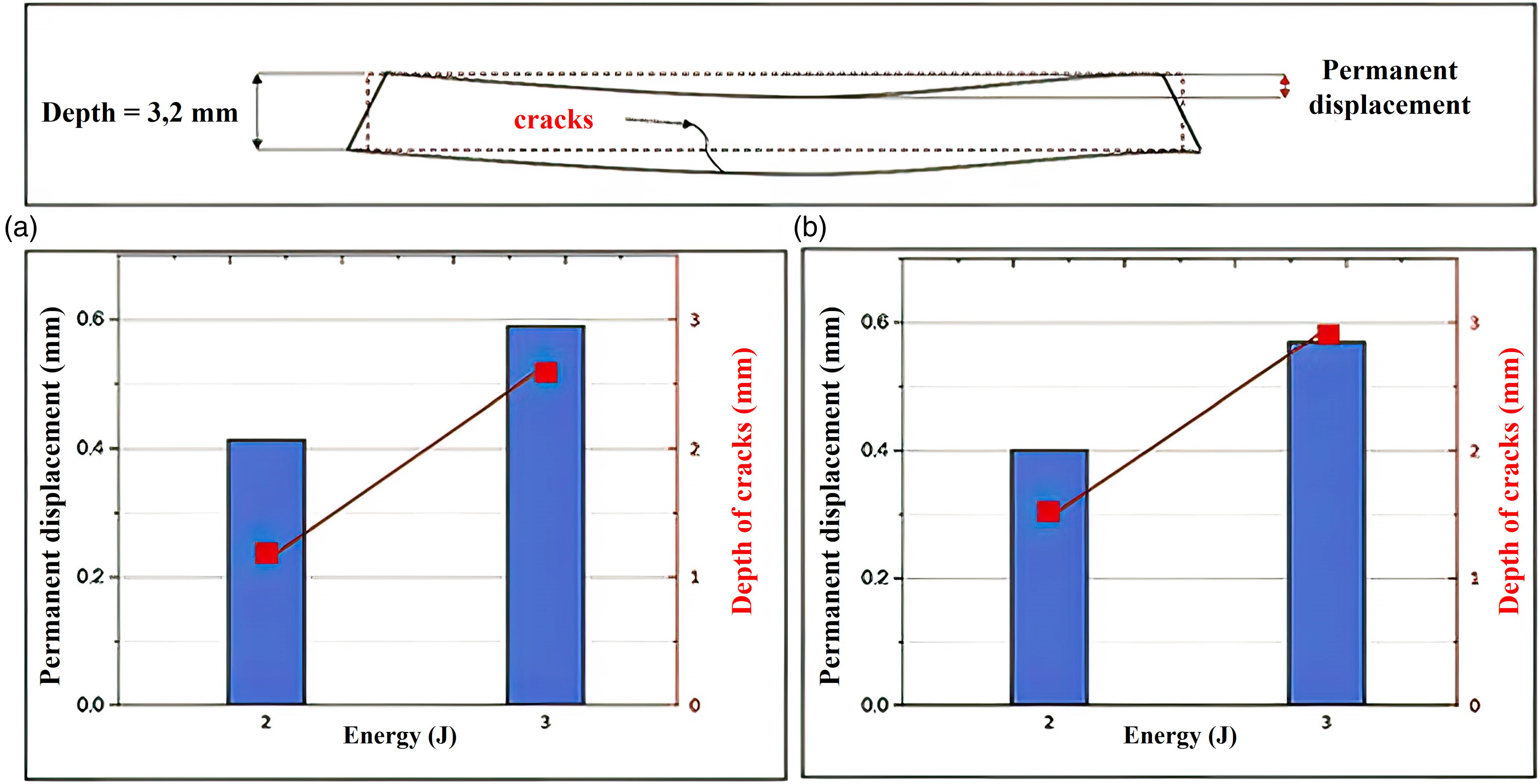
The variation in Young’s modulus with the impact energy, as measured by the pulse excitation technique, is shown in Figure 13. If an event (impact) changes the structure of the specimen, then this property is affected. Based on our results, we concluded that the stiffness of the material decreased as a linear function of the impact. The impact-induced damage contributed to a proportional decrease in the material’s Young’s modulus. However, the degradation was more important in PP30-F than in PP30-P; it was dependent upon the severity of the damage (crack coppice) and PP30-F suffered more damage than PP30-P at a given impact energy. Young’s modulus of polypropylene composites versus impact energy.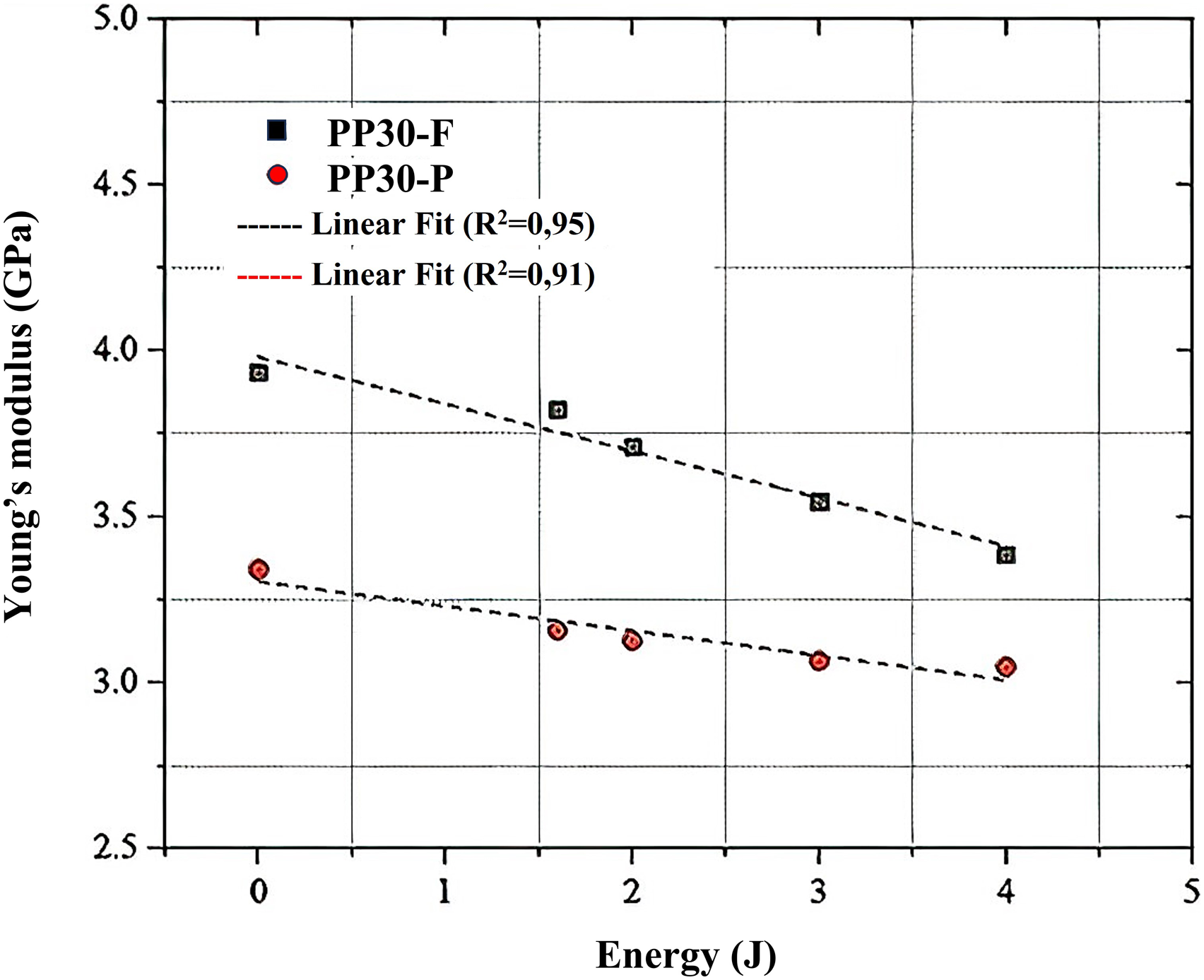
Numerical modeling
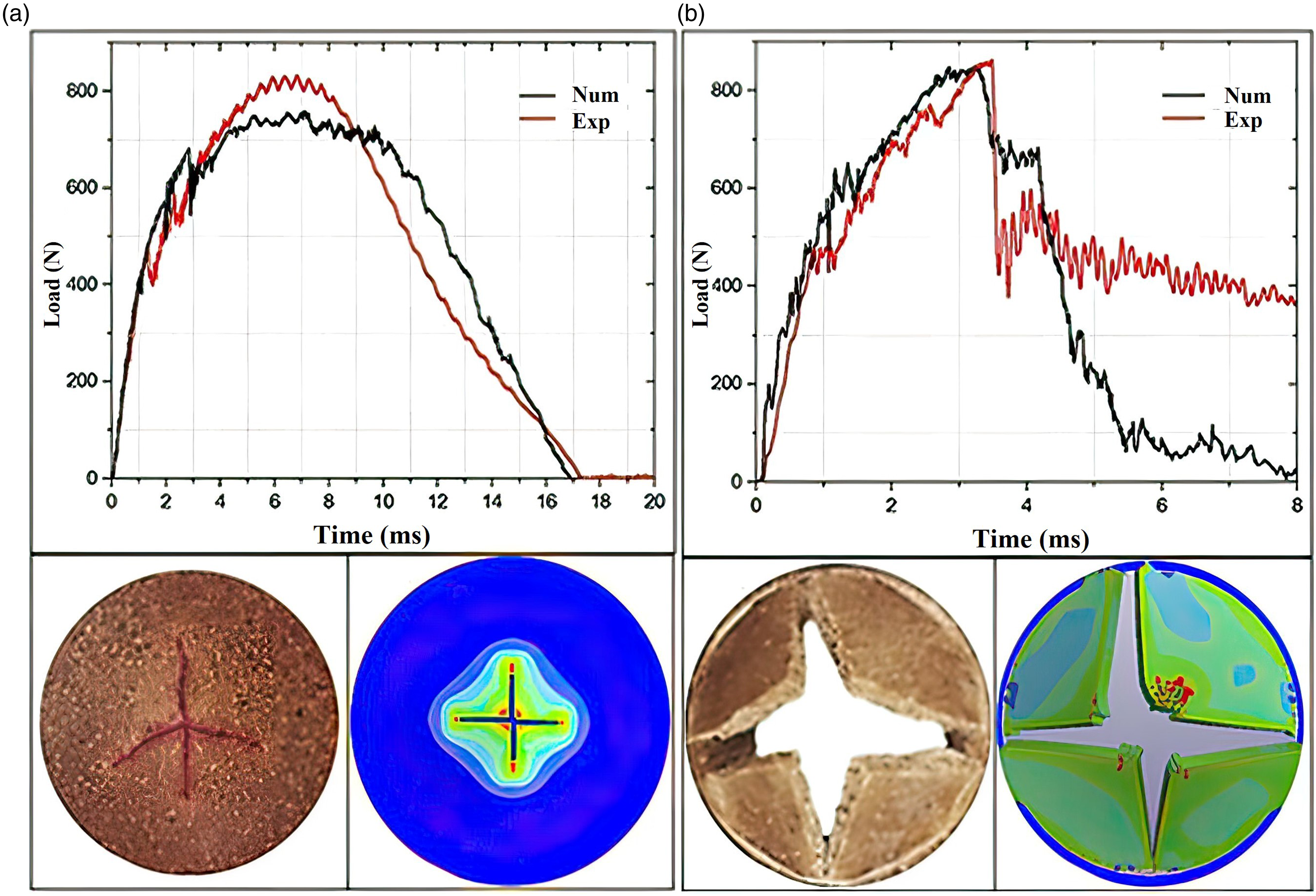
The change in strength over time during impact tests at 2 and 5 J, measured experimentally and modeled using finite elements under non-perforating and perforating conditions, are shown for the flax-fiber-reinforced composite material in Figure 14 and for pinewood-fiber-reinforced material in Figure 15. The experimental and modeled contact strength values behaved similarly at both impact energies during the initial (elastic) phase, reaching similar maxima, followed by a precipitous drop. The slight difference that appeared at this point may be attributed to the coefficient of friction and the heterogeneities present in the real specimens, which the model could not consider. The model estimated that perforation of the flax-fiber-reinforced material would occur at 7 ms, which differed from the experimental value by 0.5 ms. The corresponding values for pinewood-fiber-reinforced material were 4.5 and 4.2 ms. The images of the samples show that the model accurately predicts crack propagation in these composite materials, at least in the impact tests. Comparison of experimentally measured and finite-element-model-predicted strength over time and the corresponding surface appearances of polypropylene-flax-fiber-composite test specimens in impact tests at 2 J a) and 5 J b). Comparison of experimentally measured and finite-element-model-predicted strength over time and the corresponding surface appearances of polypropylene-pinewood-fiber-composite test specimens in impact tests at 2 J a) and 5 J b).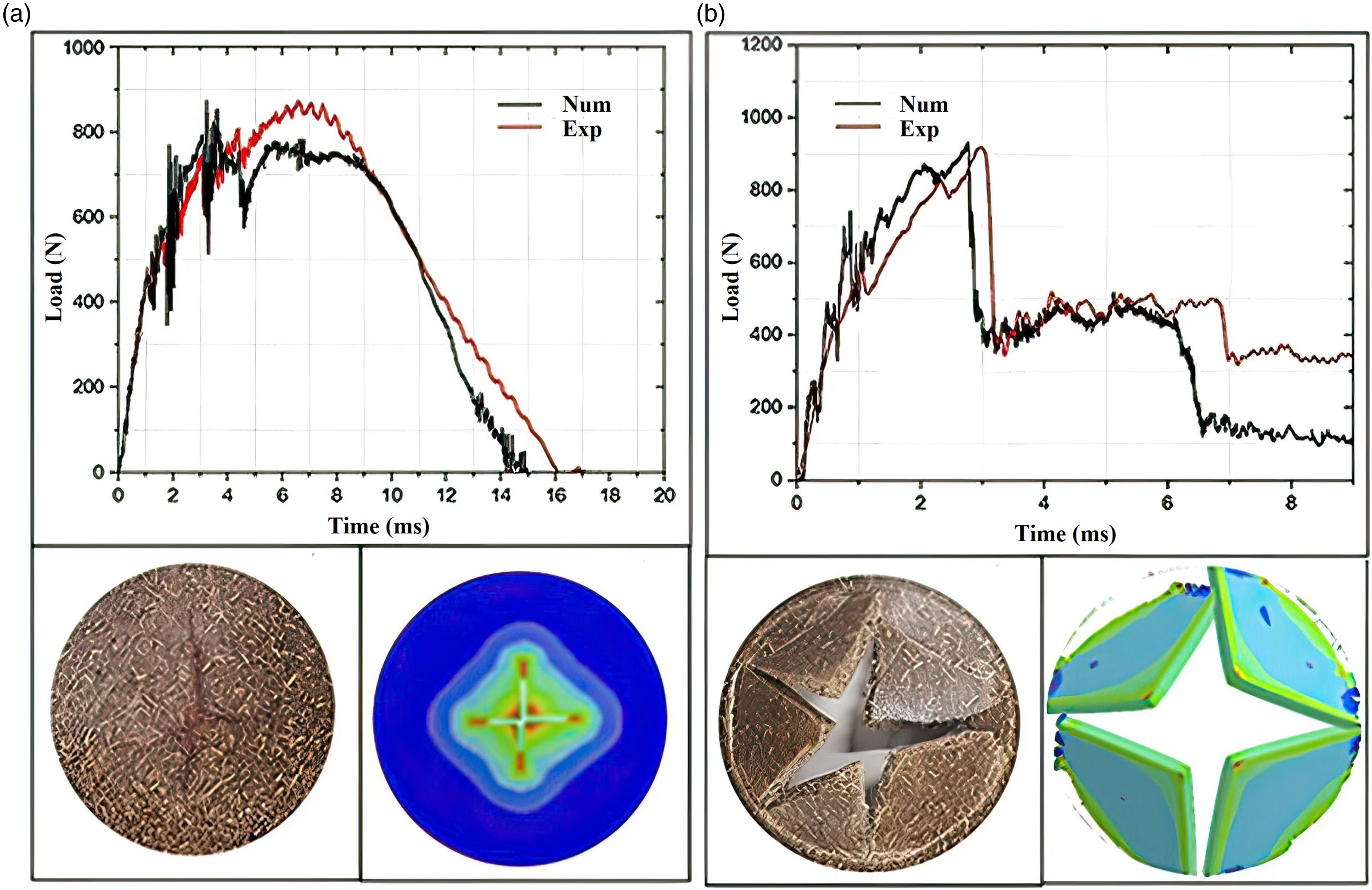
Conclusions
In this study, we compared the mechanical properties of mold-injected composite materials containing either flax or pinewood natural fibers, which were used as the reinforcing agents with PP as the matrix, using tensile and impact tests. The damage sustained by the materials under the test conditions was measured using micro-CT analysis and impulse excitation. The damage and influence of the fiber portion on the mechanical properties of the composite were modeled using a finite-element method.
The tensile test results showed that the flax-fiber composite was stiffer and stronger than the pinewood-fiber composite due to the longer length and greater surface area per unit of mass for the physical binding of flax fibers with the matrix polymer. The higher percentage of cellulose and hemicellulose in flax fibers also contributed to their superior mechanical properties. However, the stronger affinity of pinewood fiber lignin for PP resulted in greater ductility of the composite PP-pinewood material. Acoustic Emission analysis showed that the superior mechanical properties of the flax-fiber composite were likely due to better fiber-matrix cohesion. Moreover, by using acoustic emission, we were able to establish that there was a greater extent of fiber decohesion in PP30-P compared to PP30-F. This study confirms that the damage mechanisms are highly material dependent.
The impact test results revealed that the flax-fiber-reinforced plastic exhibited higher maximum strength, while the pinewood-fiber-reinforced plastic absorbed more energy. This material was also less deformed, indicating that it absorbed less energy than the pinewood-fiber composite. For both materials, the cracks induced by the impact were proportional to the initial impact energy upon drop. These cracks significantly decreased the stiffness from an impact energy of 3 J or more. Nondestructive techniques such as micro-CT analysis were effective in visualizing internal damage and understanding the processes of damage propagation induced by impact.
The numerical model developed using finite elements was found to be skillful in predicting the impact behavior of composite materials. The agreement between the experimental results and model-generated values for the contact strength and crack size time course was good. The model is thus valid and could perhaps be used to predict the impact behavior of these two bio-composites on a large dimensional scale. Bio-composite materials are very sensitive to climatic aging. In future work, the effect of aging on impact behavior bio-composites should be investigated and in particular, the influence of lignin and its role in stabilizing the impact performance after the UV irradiation.
Footnotes
Acknowledgements
The authors thank Professor Redouane Zitoune from Institut Clément Ader, Toulouse France, for providing micro-CT measurements, and the National Sciences and Engineering Research Council of Canada for funding this research.
Author Contributions
Khaled Nasri: Lead author, scientific experiments, and writing. Lotfi Toubal: project funding, writing - revision and editing. Eric Loranger: revision.
Declaration of conflicting interests
The author(s) declared no potential conflicts of interest with respect to the research, authorship, and/or publication of this article.
Funding
The author(s) disclosed receipt of the following financial support for the research, authorship, and/or publication of this article: This work was supported by the Natural Sciences and Engineering Research Council of Canada (2460134).