
Abstract
In the last years, aeronautical industry has developed certified composite patch bonded repairs for damage tolerant structures, but only restoring metallic components. The mechanical behaviour of composite bonded repairs has been investigated since the development of composite damage tolerant structures is directly dependent on this technology. This study presents a strength prediction on carbon-epoxy adhesively repaired component, using ARALDITE® 2015 for the repairing and recurring to ABAQUS®, applying cohesive zone modelling (CZM), four different load conditions: tension, compression, upward bending and downward bending were tested. Four types of repairs are analysed: Single-Strap, Double-Strap, Scarf and Two-Stepped. The obtained results state that the Double-Strap repair withstand higher loads considering all the applied load cases when compared with the other geometries. Scarf and Two-Stepped repairs could achieve promising behaviours and they should be optimized, considering the advantages related to embedded patch repairing. Generally, the overlap length revealed to favour higher strengths, specially increasing from 5 to 10 mm. Failure paths were demonstrated, revealing proper relations with strength predictions.
Introduction
Since the late 80’s, the aeronautical industry has been developing and applying composite bonded repair methodologies, but only on damage tolerant metallic structures. The literature presented by A. Baker et al., in 2002, 1 demonstrates all the research involved through the years. Nowadays, novel aircraft structures are manufactured using composite materials, as Airbus A350 and Boeing B787, but the industry still relies in “infinite-life” design philosophy. The main obstacle for the use of damage tolerant philosophy in composite structures are the development of non-destructive inspection (NDI) techniques, maintenance planning and repair. Braga et al., in 2014, 2 mentioned the importance of those factors in assuming a damage tolerant design in composite structures.
In order to achieve a mature development state on composite bonded repairs, the corresponding mechanical behaviour should be investigated, exposing numerical modelling approaches, experimental techniques, and advanced optimisation methodologies.3–8 In research, it has been demonstrated that the studies on the fracture characterisation of adhesively bonded joints,9–13 can be also applied on bonded repairs.
The application of cohesive zone modelling (CZM) in adhesive repairs was demonstrated by de Moura, in 2015. 8 Floros et al., in 2015, 9 developed a CZM approach to predict the failure of composite bonded joints under pure mode I, pure mode II, and mixed-mode I+II. For this purpose, experimental tests were performed: double-cantilever beam (DCB) test for pure mode I, end-notched flexure (ENF) test for pure mode II, and mixed-mode bending (MMB) test for mixed-mode I+II. The fracture toughness values for pure mode I (GIc), and pure mode II (GIIc) are obtained from the experimental tests. A triangular CZM approach, using γ = 1 was used for the numerical simulations using an explicit finite element (FE) code. The developed CZM predicted with notable accuracy the entire failure behaviour under mode I. Nevertheless, under pure mode II and mixed-mode I+II, the CZM predicted the mechanical behaviour until the crack initiation occurs. After that, the numerical approach failed to predict the joint strength, due to localized mechanical properties in crack tip region. In fact, the numerical analysis considered globalized properties obtained from experimental tests. The authors mentioned that additional modifications are needed for the traction separation law in order to reach a satisfactory accuracy for the strength prediction under pure mode II and mixed-mode I+II. This study clearly shows the difficulty of developing a CZM approach when mode II is presented. de Moura et al., in 2008, 10 proposed a data reduction based on a crack equivalent concept avoiding the need to monitor the crack propagation, which is very difficult in this type of test, also considering the energy dissipated in the fracture process zone. These methodologies were sufficient to overcome the limitations and a trapezoidal CZM law was derived achieving good results when compared to the experimental data. The proposed experimental methodologies could help to improve the numerical accuracy, but the adaptability of a CZM law shape is also a factor according to Fernandes et al., 11 Azevedo et al., in 2015, 12 used a triangular CZM law for mode II achieving satisfactory results according to the experimental data, especially using ARALDITE® 2015. In fact, the use of triangular CZM approaches are frequently used with success to predict the static strength of bonded repairs and adhesive joints, but a proper validation must be taken into account. For a future perspective, advanced techniques have been developed in order to reach optimized CZM laws. Freed et al., in 2022, 13 proposed a probabilistic machine learning strategy for the construction of a CZM approach. From 88 experimental tests and 2000 finite element (FE) simulations, optimized CZM parameters were assessed by Gaussian process regression.
Moreira et al., in 2020, 14 analysed several composite bonded repair geometries, in bending. The authors presented five geometries: Single-Strap, Double-Strap, Scarf, Single-Step, and Double-Step. These are the most commonly used in the aeronautical industry,. 1 Campilho et al., in 2008, 15 applied trapezoidal CZM laws for both pure mode and mixed-mode loading, in order to predict the tensile behaviour of Carbon Fibre Reinforced Polymer (CFRP) Single-Strap repairs. A satisfactory agreement with the experimental data was found while evaluating the P-δ curves. A strength above 3kN was reached. The authors investigated the effect of the overlap length and patch thickness. The increase in the overlap length favoured the increase in strength, but it can be decreased by an increase of the patch thickness in a certain range. For the Double-Strap, Lee et al., in 2009, 16 performed an experimental investigation using Glass Fibre Reinforced Polymer (GFRP) adherends. While analysing the effect of the adhesive type, adhesive layer thickness and overlap length, the authors proved the superiority of Double-Strap over Single-Strap repairs, in tension. The adhesive type had an insignificant effect on strength, while the decrease of the adhesive layer thickness and the increase of overlap length favoured clearly the increase in strength. Campilho et al., in 2009, 17 using three-dimensional models, also proved the superiority of Double-Strap over Single-Strap repairs, in terms of strength under tension, but using CFRP adherends. The overlap length and patch thickness effects were analysed. The study showed a significant increase of the strength when the overlap length increases from 5 mm to 15 mm. The patch thickness had negligible effects on the repair strength. Analysing Scarf repairs in tension, Campilho et al., 18 proposed different cohesive models based on trapezoidal traction separation laws, allowing the prediction of cohesive, interlaminar, and intralaminar on both fibre and transverse directions. In fact, for very low scarf angles, complex cohesive-interlaminar, and intralaminar failures were verified experimentally. A very good accuracy was achieved according to the experimental evidence. The authors proved that both the strength and compliance decrease exponentially while the scarf angle increases. Regarding strength, and taking into account a physical range of scarf angles, a 50% of strength reduction is observed from using 5°–15°. Still analysing Scarf repairs, but with a three-dimensional FE model, Pinto et al., in 2010, 19 also emphasized that the strength decreases exponentially with the increase in the scarf angle. The authors also tested the possibility of having over-laminated plies, reporting a maximum repair efficiency of 70% for lower scarf angles. This increases significantly the strength restoration; however, it demonstrates several disadvantages aerodynamically, but only when optimized. Advanced optimization methodologies have been proposed by several authors, from 15 years ago until nowadays.20,21 Breitzman et al., 20 optimized the Scarf repair system to minimize the stress level in the adhesive, under tension. The major parameters involved were the patch ply orientations. Using an over-laminating ply over the scarf repair, the authors reported a 90% of strength restoration, as an optimal result. Step repairs have also been studied. Ichikawa et al., in 2008, 22 performed a stress analysis and strength evaluation on stepped-lap adhesive joints in tension, investigating the effect of the adhesive Young’s modulus and thickness, and number of steps. The increase of the Young’s modulus and number of steps allowed a decrease in the stress level in the adhesive, and consequently, improving the joint strength. However, an increase of the adhesive thickness showed a strength reduction.
In this work, four types of repair systems (Single-Strap, Double-Strap, Scarf and Two-Stepped), considering four different loading cases (tension, compression, upward bending and downward bending) were analysed numerically, using finite element analysis including cohesive zone modelling. In addition, three overlap lengths for the Single-Strap, Double-Strap and Two-Stepped, and three angles for the scarf repair were considered. These conditions gave rise to a total of 12 numerical models and 48 analyses. The simpler triangular cohesive zone law was assumed for simplicity. The cohesive elements were placed at the critical regions prone to damage initiation and growth, aiming to replicate the failure paths and estimate the repair stiffness and strength. Important conclusions regarding the several repair strategies and loading scenarios have been drawn.
Methodologies and developments
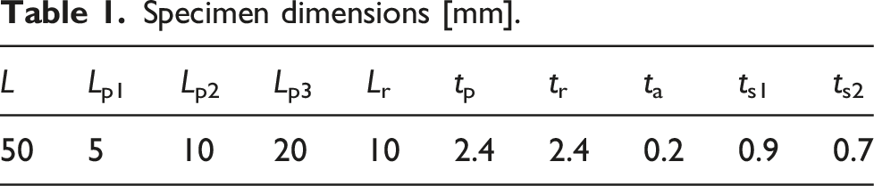
The present section describes the numerical methodology in order to predict the strength of different types of repair configurations, while analysing the corresponding failure path. For this purpose, geometry, material properties, including the CZM, mesh, and boundary conditions are stated. This work addresses four repair geometries considering a constant width of 25 mm: Single-Strap, Double-Strap, Scarf and Two-Stepped (Figure 1). The strategy of Single-Strap and Double-Strap repairs consists on removing the damaged part of the specimen and bonding one or two external patches to that region. The latter option is only possible when both sides of the structure are accessible. The Scarf repair also follows the same strategy but a chamfered patch is embedded in the structure, in a way that sets up a smooth surface. The Two-Stepped repair method is identical to the previous one, however the chamfered patch is substituted by a stepped patch. Three different overlap lengths (identified in Table 1 as Lpi, i = 1, 2, 3) were considered for all cases. Overlaps of 5, 10, and 20 mm correspond to angles of 25.6°, 13.5°, and 6.8°, respectively, for the Scarf repair. All of the specimen dimensions used in these studies are included in Table 1. Geometries and loading conditions: (a) Single-Strap under tensile, (b) Double-Strap under compression, (c) Two-Stepped under upward bending, (d) Scarf under downward bending. Specimen dimensions [mm].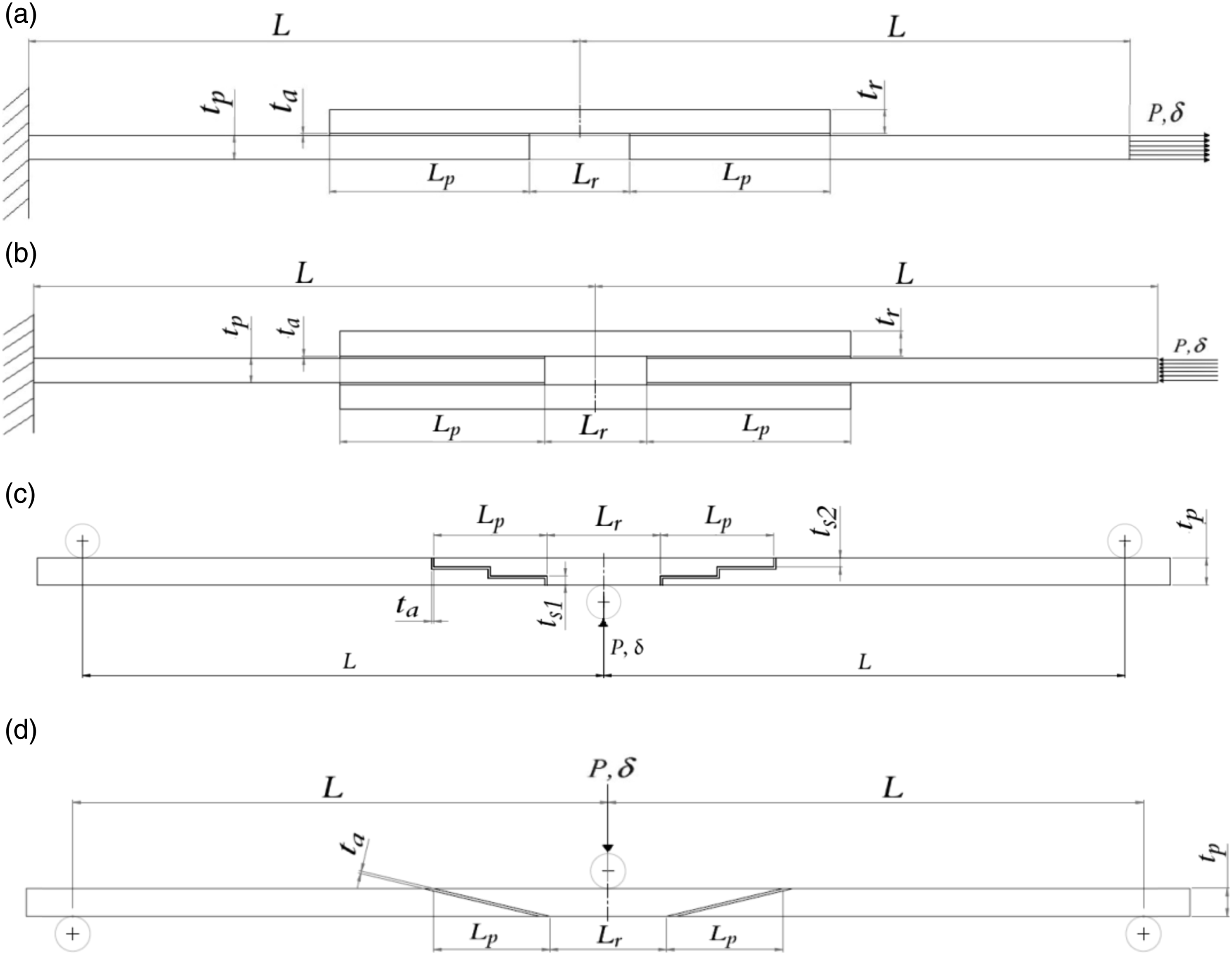
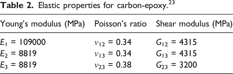
Elastic properties for carbon-epoxy. 23
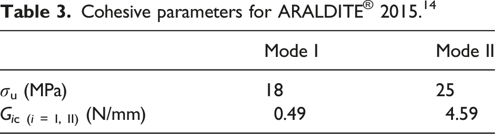
Cohesive parameters for ARALDITE® 2015. 14
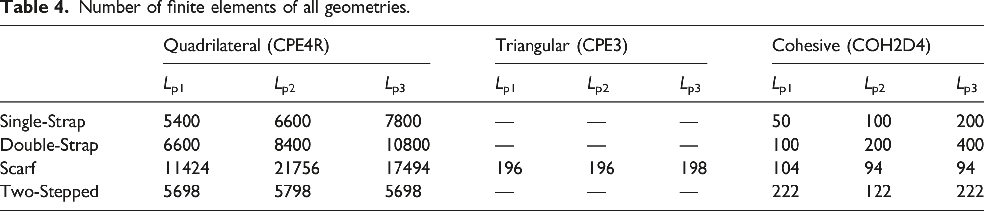
Numerical analysis was performed using ABAQUS® as FE software. The two-dimensional FE models were built with refined meshes. The elements used were four-node quadrilateral elements with reduced integration and in some regions of the Scarf repair it was used three-node triangular elements for geometrical transitions. Those elements are plane-strain solid continuous elements, CPE4R and CPE3, respectively, according to ABAQUS® nomenclature. For the adhesive layer, compatible 4-node quadrilateral cohesive elements were used. Following the software nomenclature, it corresponds to COH2D4 elements. A mesh of 0.2 mm element thickness was created in the region corresponding to the adhesive layer. The mesh was refined at the extremities of the adherend, using a double bias approach. This command allows to refine the mesh at the ends, where stress concentrations are presented, making it coarser in the middle. This has the advantage of increasing the efficiency in terms of computational cost, while still capturing stress concentrations, which are observed in the overlap region, and accurately registering reaction forces. Moreover, in the thickness direction, a constant mesh was imposed, as well as in the longitudinal direction for the zone corresponding to the bonding line. Therefore, the element presents 0.2 mm along their height. To enhance the mesh details, only half of the repair is shown in Figure 2, under symmetric conditions. The number of solid and cohesive elements are presented in Table 4. Finite element meshes used in (a) Single-Strap, (b) Double-Strap, (c) Scarf, (d) Two-Stepped. Number of finite elements of all geometries.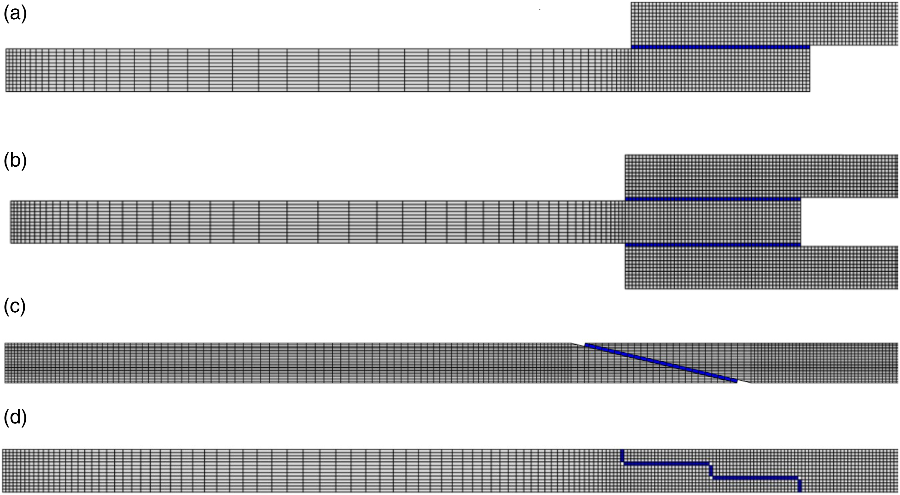
Four types of loading were simulated: tensile, compression, bending upwards and downwards. The loading cases are presented in Figure 1. For the first two, the loading is applied to the tip edge (right), while the other tip edge is clamped (left). In the other cases, the loading is applied at the central node while the extreme inferior nodes, in each side, are imposed as simply supported, simulating a 3-point-bending (3PB) test. This methodology is based in Moreira et al. 14 It is noteworthy that all loading cases are applied to all repair geometries, constituting a total of 16 case studies.
Results and discussion
A strength analysis, for Lp = 10 mm, was performed, in The Strength analysis, relating the four types of geometry presented above. The differences observed between geometries and load types are described, and the best repair configuration is associated to each of the studied load cases. In this same section, the effect of the overlap length is analysed. Failure paths are also demonstrated in section 3.2, describing the damage initiation behaviour as well as the type of failure and a discussion is also performed outlining differences between geometries and load cases.
Strength analysis
A strength analysis for each load case, tension (3.1.1), compression (3.1.2), upward bending (3.1.3), and downward bending (3.1.4), is presented in this subsection. The effects of the overlap length is also accessed for each load case.
Load case 1: Strength in tension
Considering the tension load case, Figure 3 displays the load–displacement (P-δ) curves for all repair types. P-δ curves for tension load case.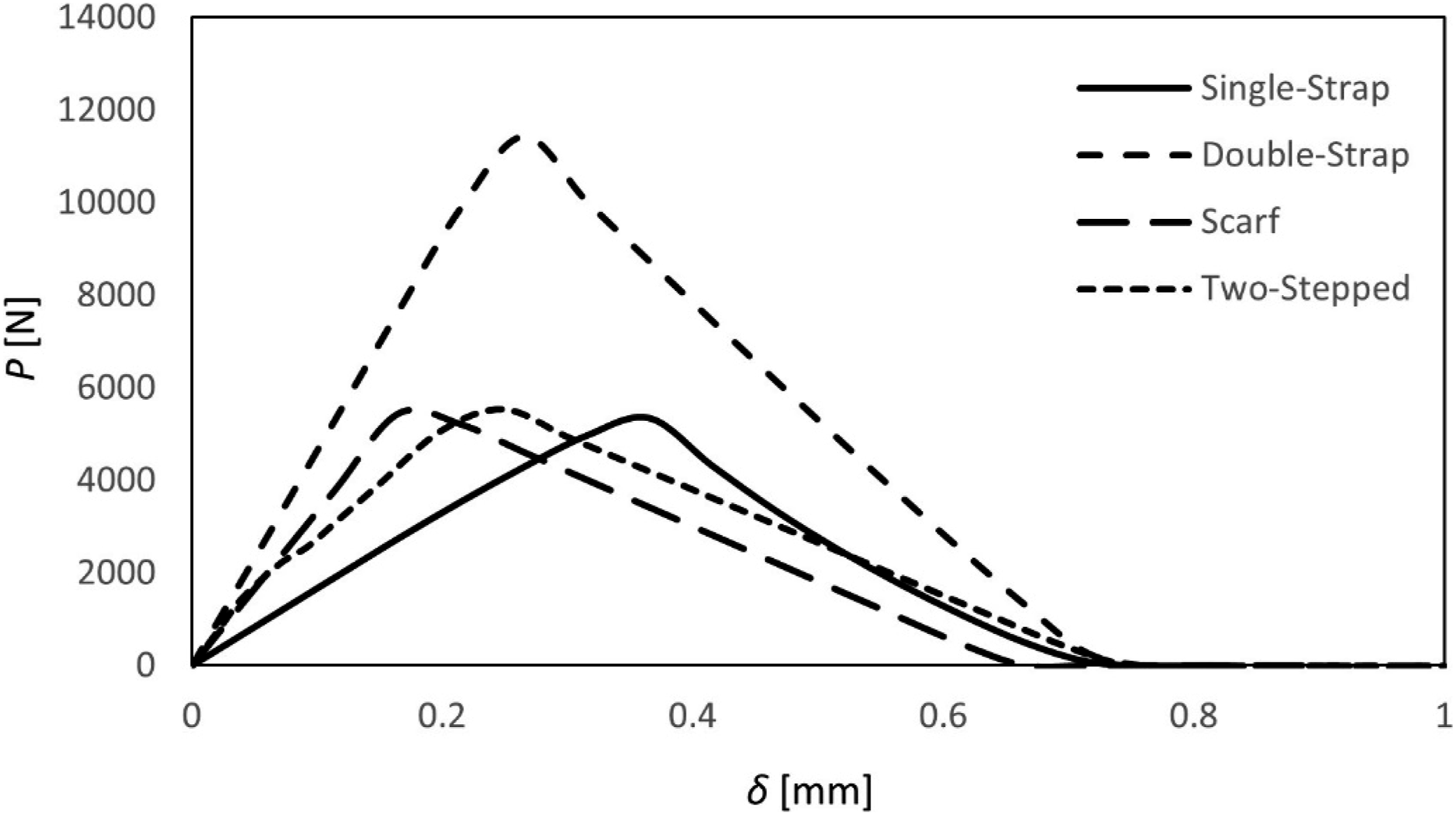
Under tension, the Single-Strap model presents failure at a load of 5350 N. Its respective displacement corresponds to 0.37 mm, revealing the lowest stiffness. The Double-Strap repair sustained 11400 N before failure, for a displacement of 0.27 mm, which is 27% lower than the one revealed for Single-Strap. This model demonstrated the highest stiffness and strength since its peak load is the highest among other models. Thus, it is observed that the peak load of the Double-Strap is approximately twice of the other geometry repairs.
Regarding the Scarf model, this presents 5440 N loading before failure for a displacement of 0.17 mm. The strength level showed to be very similar when compared to the Single-Strap, however presenting a displacement at failure 54% lower. The preference for a higher compliance, in this case, would prejudice the aerodynamic efficiency, which is relevant in aerostructures. In fact, Scarf is totally favourable among Single-Strap for applications when a higher stiffness is required.
In turn, the Two-Stepped repair reveals failure at 5550 N, also identical to Single-Strap and Scarf. A displacement of 0.25 mm was registered, which is similar to Double-Strap case. The demonstration of these results allow to conclude that, under tension, the superiority of Two-Stepped among Scarf is clear if a higher compliance is needed, still assuring an aerodynamic efficiency.
Thus, it is stated that the Double-Strap presents the highest strength under tension, since it is the most reinforced in terms of bonded area, while avoiding secondary bending effects, minimizing peel stresses and stress concentrations at the end of adherends. Nevertheless, for aeronautical structures, embedded patches are more common as mentioned above. The strength given by Scarf and Two-Stepped are sufficient, being the preferable choices. For applications when the compliance must be higher, e.g. fatigue tensile loading, Two-Stepped demonstrates to be the most favourable repair system. In fact, in this study, a Scarf considering an angle of around 13.5° was considered. Studies shown in The Introduction demonstrated an optimal strength for angles around 3°. This is justified by the fact that low angles seemed to demonstrate reduced stress concentrations on the transition corners between the patch and the adherends. Under tension, if a high strength is required, assuring the aerodynamic efficiency, a Scarf with a reduced and feasible angle should be used, although small values require a large amount of material removal.
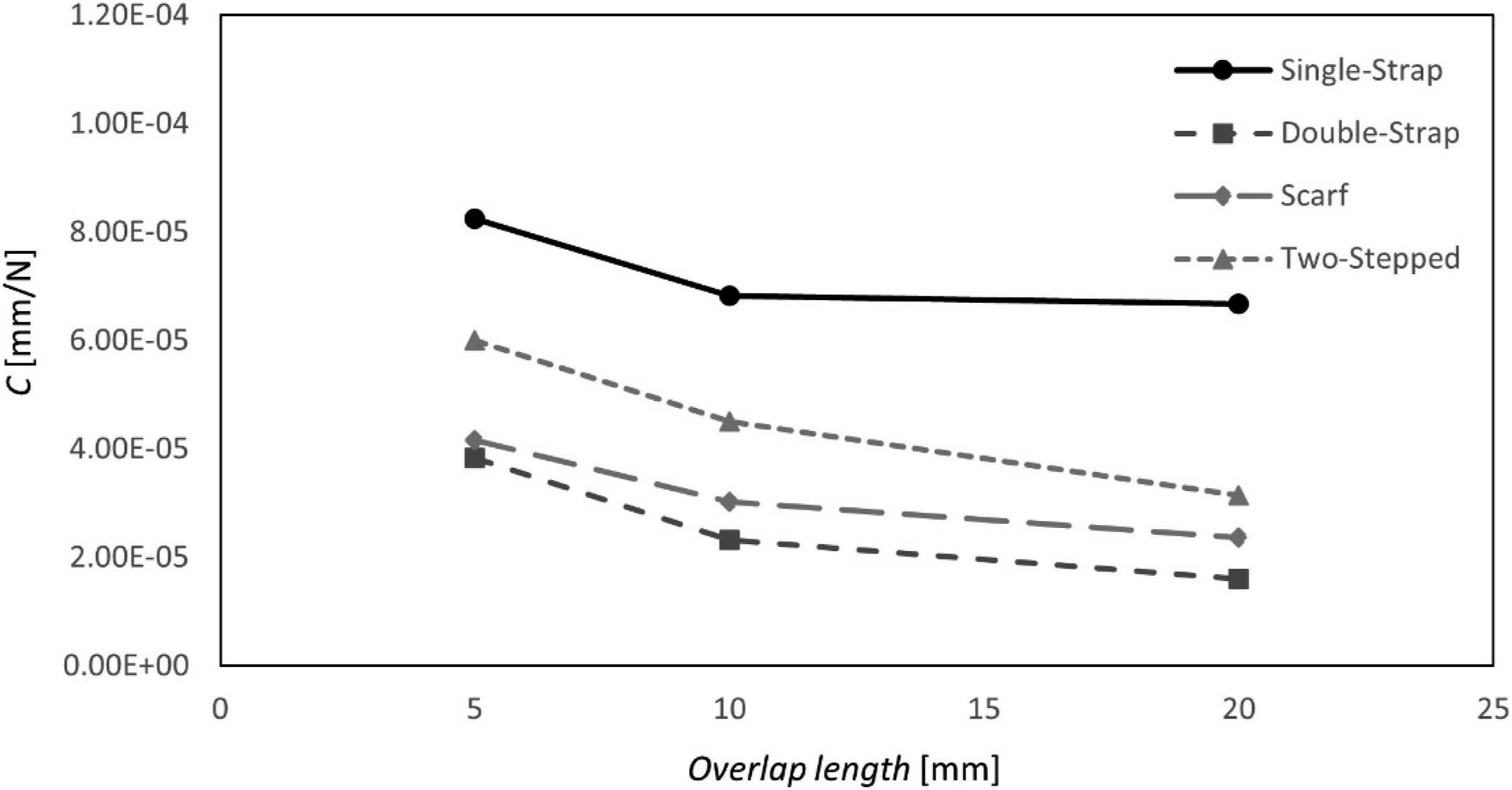
The evolution of the tensile strength for all repair types under tension with overlap length is shown in Figure 4, being detailed in Table 5. Figure 5 shows the overlap effect on compliance. Overlap effects on strength: tension. Detailed values on the overlap effects on strength: tension. Overlap effects on compliance: tension.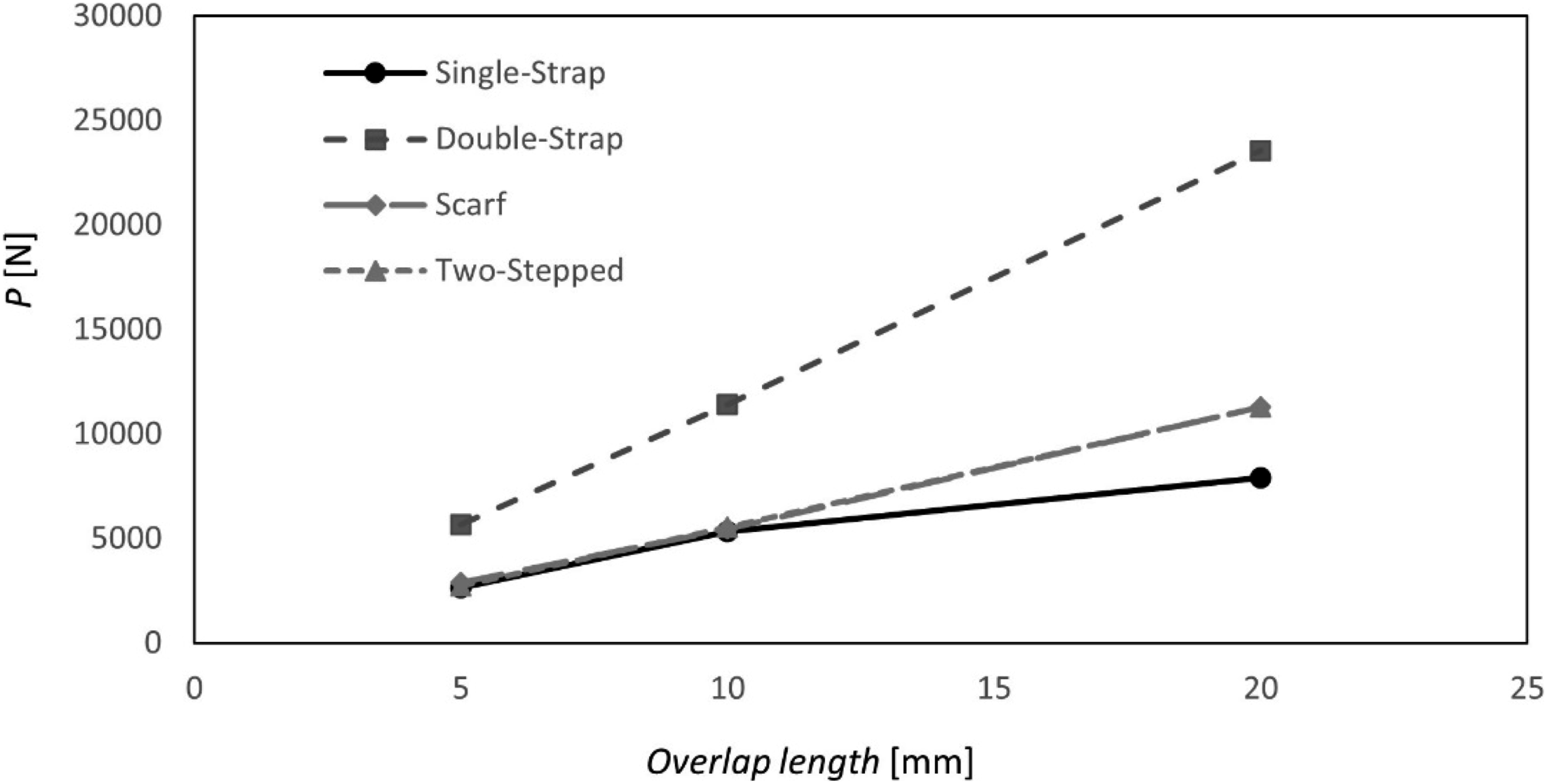
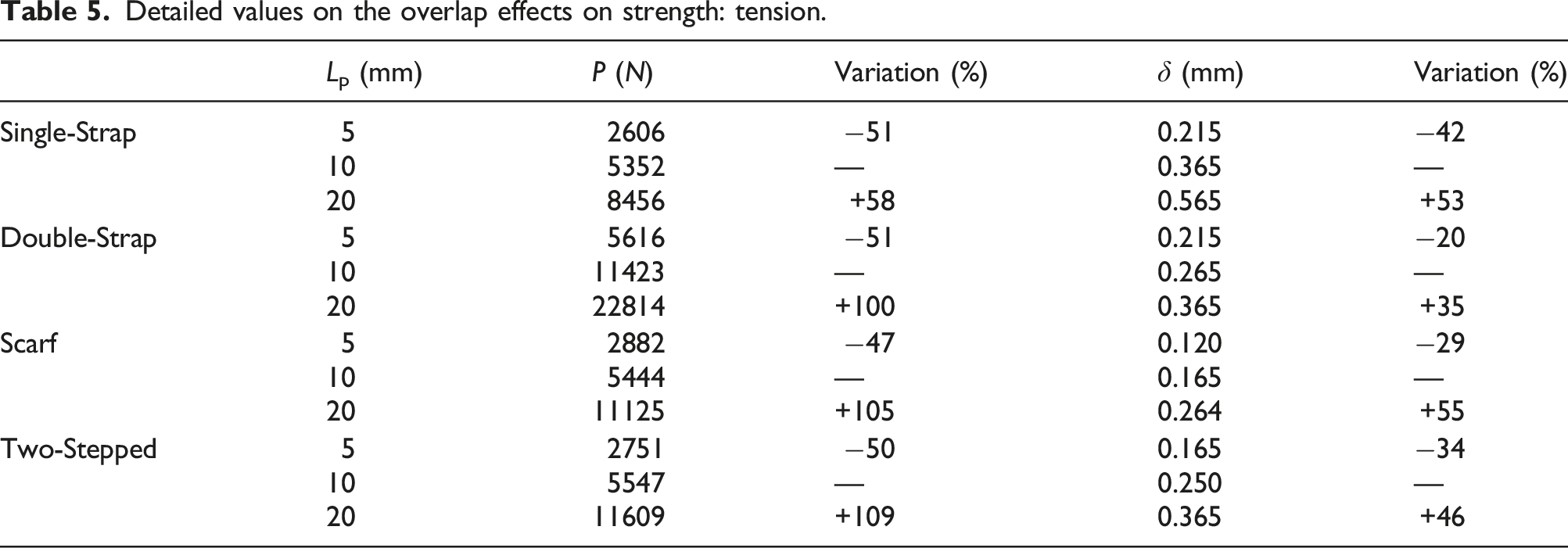
First of all, regarding strength, it is notable that the Double-Strap repair is the most influenced by the increase in the overlap length. It was demonstrated that the strength increases linearly with the highest rate, by increasing the patch size. The strength is increased by 100% when the overlap length doubles, but it decreased in 51% when it halves. Decreasing the overlap length from 10 mm to 5 mm, the displacement at failure decreases in 20%. A 35% increase in this same property is registered when the overlap length increases from 10 mm to 20 mm. Following Figure 5, the lowest values of compliance are associated with the Double-Strap repair.
Secondly, the Single-Strap repair showed to be the least influenced in terms of strength, especially, for wider overlaps. The decrease from Lp1 = 10 mm to Lp2 = 5 mm provided a decrease in strength of 51%. Nevertheless, increasing the overlap from 10 mm to 20 mm, the strength increased 58%. This allows concluding that for a Single-Strap repair, the use of an overlap length higher than 10 mm does not bring sufficient advantages in terms of performance compensating costs and repair efforts associated with wider repaired zones. Regarding the associated displacement, it is seen a decrease in 42% when the overlap length is decreased from 10 to 5 mm. However, the displacement at failure showed to increase in 53% when the overlap length is increased from 10 to 20 mm. Nevertheless, it is seen that the compliance does not change significantly from 10 to 20 mm of overlap length.
Scarf and Two-Stepped repairs presented the same tendency. From Lp2 = 10 mm to Lp3 = 20 mm, the strength increased more than 100%. Studies previously discussed in The Introduction, 19 postulated an optimal Scarf angle of 3°, corresponding of an overlap length of about 45 mm. This means that the increasing tendency continues. Considering manufacturing costs and “in situ” repair facilities, a Scarf repair with 20 mm of overlap gives sufficient strength. Regarding displacement to failure, the Scarf repair revealed a decrease in 55% when the overlap length increases from 10 to 20 mm, while a decrease in 29% is registered for a decrease from 10 to 5 mm in the overlap length. Two-Stepped repair is slightly less affected by the increase in the discussed parameter. From 10 to 20 mm, an increase in displacement at failure of 46% is registered. Nevertheless, a decrease of this same property is more prone for the Two-Stepped repair when the overlap length decreases from 10 to 5 mm. It showed to decrease in 34%. The compliance of the Scarf repair seemed to be more affected by the overlap length, in comparison to the compliance related to the Two-Stepped repair. In fact, the Scarf repair showed to be the most affected by an increase in the overlap length, in terms of compliance.
Load case 2: Strength in compression
Figure 6 presents the load–displacement curves for the studied of four types of geometry, considering the compression load case. P-δ curves for compression load case.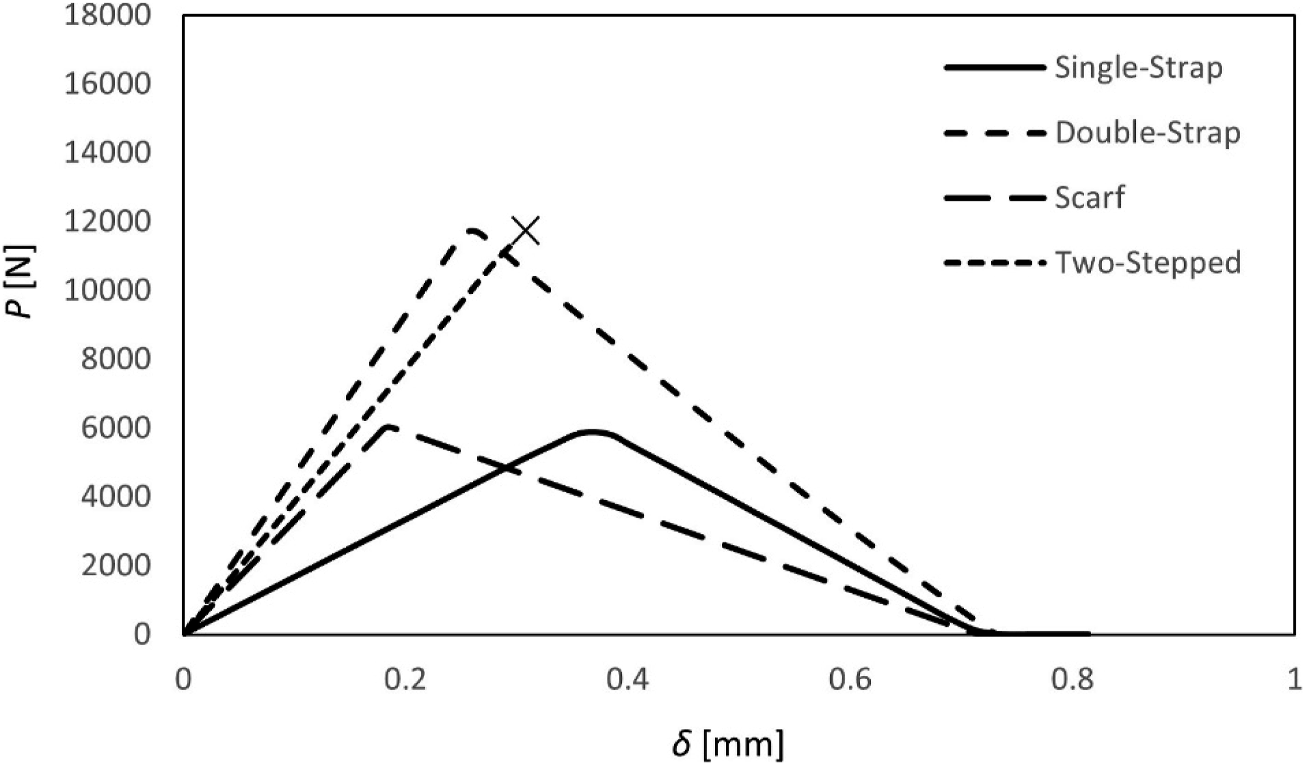
Analysing the P-δ curves presented, Single-Strap demonstrated a strength of 5850 N under compressive loads, corresponding to the lowest value. However, the damage initiation is registered for a displacement of 0.36 mm, revealing an interesting extension of the initial linear elastic behaviour, which can demonstrate a higher strain energy release rate intrinsically related with the geometry for this case.
The Double-Strap showed the best behaviour in terms of strength, sustaining 11700 N. The explanation for this characteristic is the same as mentioned above regarding tensile loadings. The absence of secondary bending effects intrinsically related with the Double-Strap geometry seemed to be clearly advantageous also under compression. The damage initiated with 0.26 mm of displacement, demonstrating a higher stiffness when compared with the Single-Strap, justified by a higher amount of overlap region.
Despite of the demonstrated behaviour and proof of strength presented in the state-of-art,14,19–21 for Scarf repairs, under compression it revealed a strength of around 6000 N, which is about 48% lower when compared to the strength achieved by the Double-Strap. Nevertheless, as mentioned above, this value has the potential to increase if the chamfer angle is decreased until 3°, despite of not being clearly proved in the literature for this load case. For future investigations, the effect of the scarf angle should be studied under compressive loads. In addition, it showed the lowest displacement at failure, presenting a damage initiation for 0.18 mm of displacement, being also 50% lower than the value registered, but now for the Single-Strap repair. This behaviour under compressive loads, for Scarf repairs, can be related with a pull-out effect of the patch, introducing peel stresses, giving rise to premature adhesive failures. The design and manufacturing of scarf repairs is more difficult when compared to other types as Single-Strap and Double-Strap,. 1 Under compression, the use of Scarf repairs seemed to be unjustifiable, being costly disadvantageous.
The Two-Stepped repair demonstrated an exceptional behaviour. A compressive load was not able to cause failure in the vertical adhesive layers. In fact, these layers are purely compressed axially, and following the numerical models associated with CZM, presented in, 14 cohesive elements do not suffer any damage under compression. Indeed, CZM seemed to not be the most suitable approach to predict the strength of this type of repair under compression. Future research must be done studying numerical approaches as extended finite element methods, 24 and meshless method, 25 applied to Two-Stepped repairs, under compressive loads. Even recurring to CZM, it is possible to ensure fundamental conclusions. In fact, there is a difference in the inclination (inflection point) in the P – δ curve when the load reaches 9850 N for a displacement of 0.26 mm. Consequently, this can be assumed as the strength of this repair system, being 0.26 mm its corresponding displacement at failure. This strength showed to be slightly lower comparing to the Double-Strap repair. Other repair models present a strength under compression very similar to the corresponding strength, but under tensile loads. However, the Two-Stepped is significantly more resistant under compression. In fact, even not capturing any damage under pure axially compressive loads in the vertical adhesive layer, that zone is less prone to failure for these conditions. In this way, it supports the repair system under compression, sustaining higher loads.
Considering this load case, the best configurations are notably the Double-Strap and Two-Stepped repairs. The presence of over-plies is disadvantageous in terms of the aerodynamic performance, demonstrated by Pinto et al, 19 which is a positive aspect of using a Two-Stepped repair, not having undesirable drag effects in aeronautical structures. On the other hand, Double-Strap repairs are easier to manufacture, however, if the repair operation is done in situ, inner faces are impossible to access in most of the cases. Considering the overall aspects, it is concluded that the Two-Stepped is the most adequate type under compressive loads. Nevertheless, this proof of strength must be validated with other numerical methods and experimentally in a future investigation.
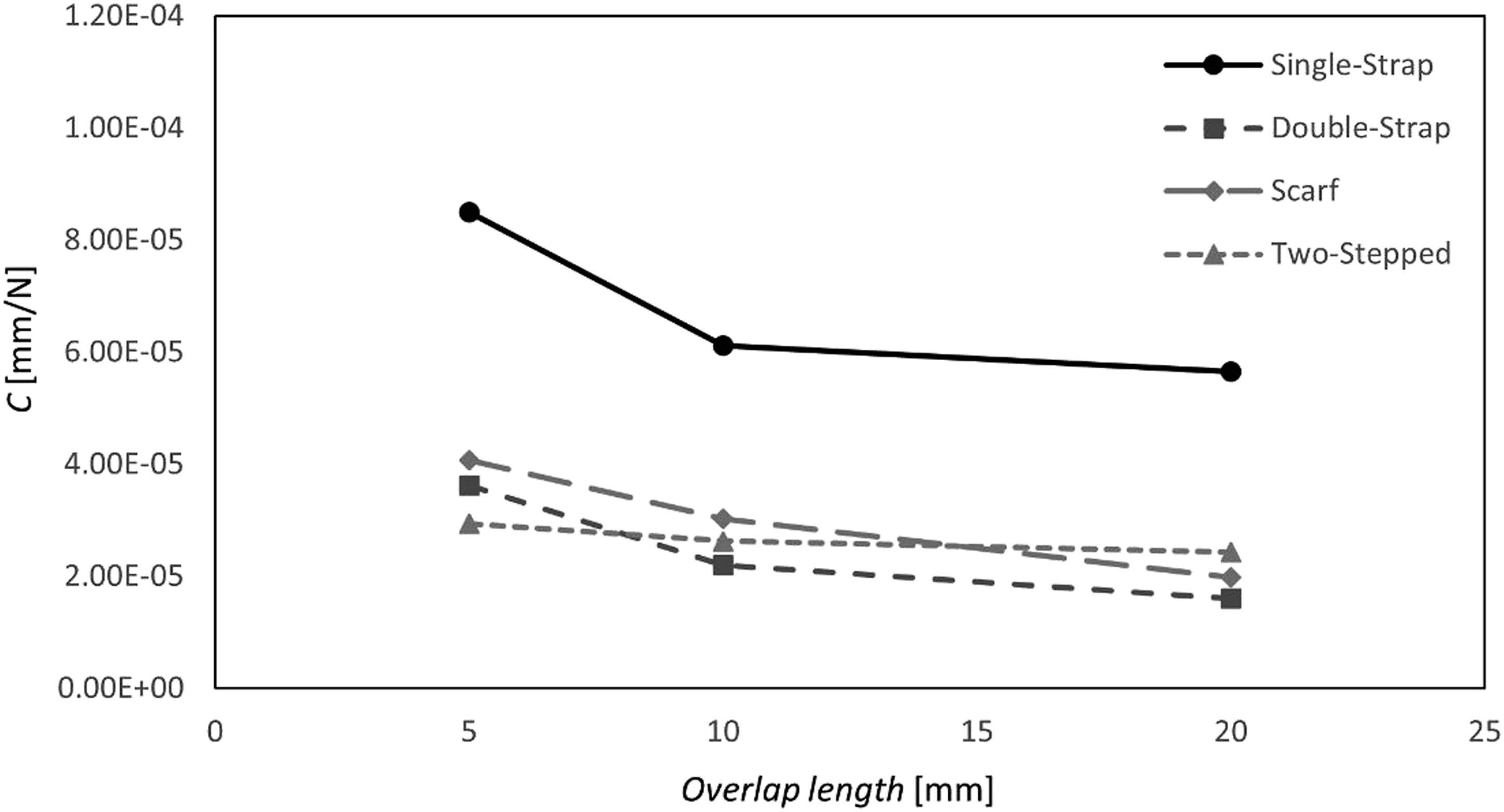
Figure 7 shows the overlap effects on strength but considering compression. The corresponding values are detailed in Table 6. Figure 8 presents the overlap length effect on compliance. Overlap effects on strength: compression. Detailed values on the overlap effects on strength: compression. Overlap effects on compliance: compression.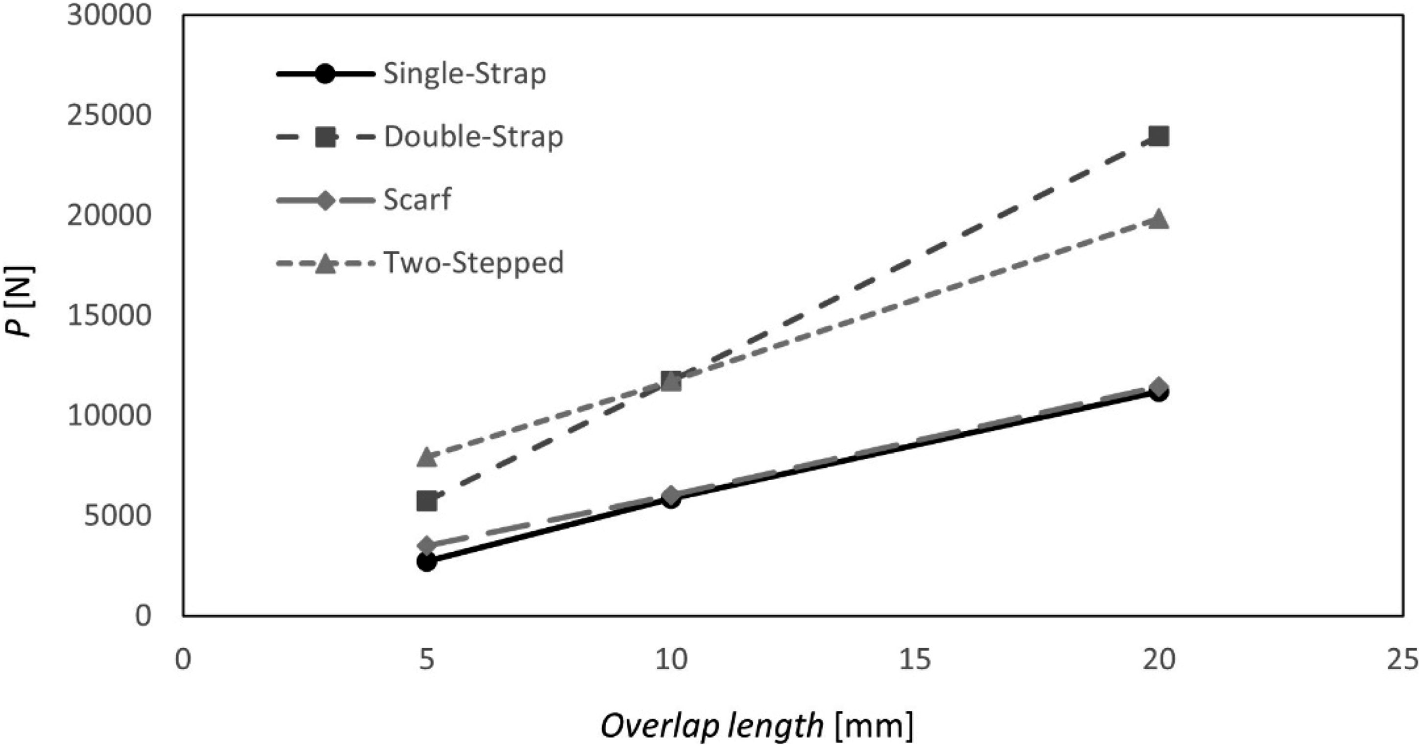
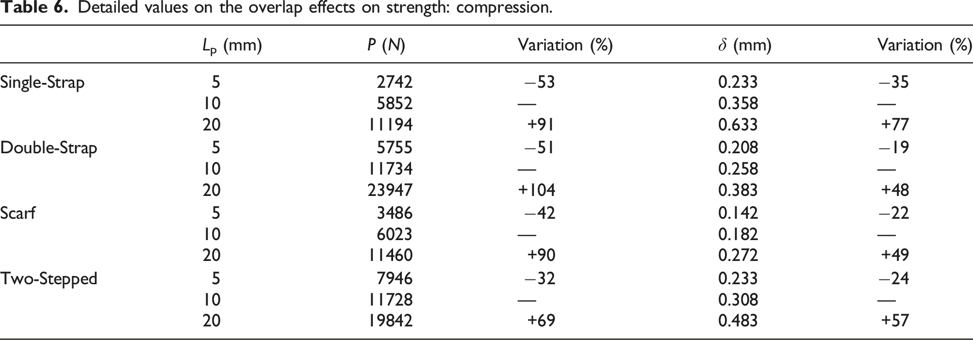
Generally, the overall tendency is identical in comparison to the tension load case. The Double-Strap is also the most influenced regarding the repair strength. It is increased in 104% when the overlap length is increased from 10 to 20 mm. Nevertheless, changes in the displacement to failure are the least affected. Decreasing the overlap length from 10 to 5 mm, the displacement, under failure, decreased only 19%.The value of 48% of increase in displacement at failure was registered increasing the overlap length from 10 to 20 mm. The Double-Strap repair presents the lowest values of compliance for high overlap lengths.
Single-Strap repair is less affected in terms of strength, but only comparing to the Double-Strap. A decrease in strength of 53% is registered for an increase of overlap length from 5 mm to 10 mm, while 91% of strength improvements was verified increasing from
Scarf revealed a similar tendency in comparison to Single-Strap, in terms of strength improvements. A 90% improvement is achieved by increasing the overlap length. A decrease of strength in 42% is demonstrated when using 5 mm of overlap, instead of 10 mm. In terms of displacement to failure, the behaviour is more similar to the Double-Strap, showing an increase of 49% when the overlap length is increased. This same property is decreased in 22% by decreasing the overlap length from 10 to 5 mm. The Scarf repair showed to be still influenced by the overlap, in terms of compliance, for lengths higher than 10 mm.
The Two-Stepped showed to be the least influenced in terms of strength. Only 69% of improvements was achieved by increasing the overlap length from 10 to 20 mm, and only 32% of the sustained load was decreased by shortening the overlap length. In terms of displacement, it showed to be less influenced, but only comparing to a Single-Strap repair. An increase in the overlap length allowed an increase of 57% in the sustained displacement. The displacement corresponding to the maximum strength showed to decrease in 24% by decreasing the overlap length from 10 to 5 mm. In terms of compliance, this type of repair showed to be the least affected by changes in the overlap length, demonstrating almost linear variations in the studied range.
Under means of manufacturing and repair facilities, and if it is possible and needed, all types of repairs can be optimised using larger patches. It can be reasonably assumed that the strength increases linearly with the increase in the overlap length, in the studied range, and it can be considered in design. Although, a special attention must be given to the Scarf repair, due to proper characteristics mentioned above, following optimizations proposed in. 19
Load case 3: Strength in upward bending
Figure 9 presents P – δ curves for the analysed four types of geometry, considering the upward bending load case. P-δ curves for upward bending load case.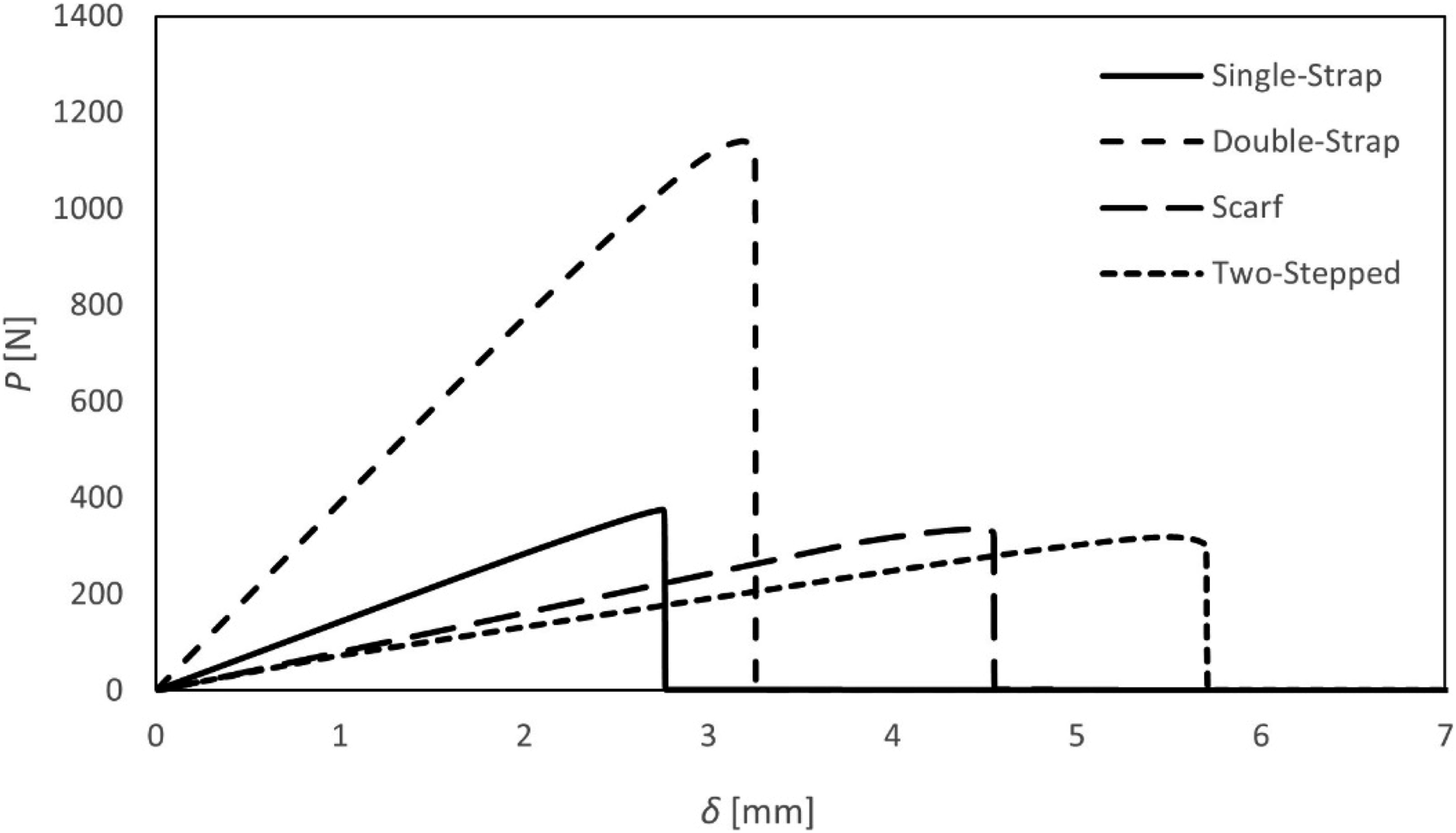
The Single-Strap model failure initiation occurred at a load of 375 N and a displacement of 2.75 mm. It is verified that this type of repair presents the lowest displacement at failure. Upward bending introduces strong peel loads in the patch, which explains the low stiffness due to a premature failure, but also the low strength that was registered.
Regarding the Double-Strap model, a strength of 1127 N is registered, as well as a displacement of 3.25 mm. From these values, it is proved that the Double-Strap presents a strength that is 67% higher when compared to the Single-Strap. This discrepancy is more significant than the one presented for axial loads. In fact, the patch applied in the lower surface allowed to reduce the peel stresses in the adhesive layer associated to the patch that is being directly pulled up. Those peel stresses are, in part, distributed to the bottom adhesive layer. This feature seemed to have also an effect in stiffness. Despite of having a higher amount of material, the displacement at failure is increased in 15%, due to peel stress alleviation reducing the catastrophic level of the corresponding failure. Despite of the difficulties in implementing an in situ Double-Strap repair, it demonstrated a great potential for aeronautical applications in terms of mechanical behaviour.
In the case of the Scarf repair, the results showed a strength of 320 N, with a displacement of 4.52 mm. An upward bending load also pull-out the patch for the Scarf repair, introducing higher peel stress concentrations in the adhesive layer ends. In fact, related to the inclination of the adhesive layer, on which peel stresses are slightly more significant than the ones verified for a Single-Strap repair, presenting a strength that is around 15% lower. Oppositely to it was referred for tensile and compression loadings, in The Load Case 1: Strength in Tension and Load Case 2: Strength in Compression, respectively, the increasing in the scarf angle can increase, in this case, the peel stresses, consequently increasing the percentage of mode I loading. In this way, decreasing that angle could increase the strength under upward bending. Despite of these issues related with strength, low stiffness levels are verified, being higher in 28% than the ones observed for Double-Strap, and higher in 39% compared to the Single-Strap. These results proved that the failure related to a Scarf repair is less catastrophic comparing to the failure observed for the Single-Strap. Failure catastrophic levels are discussed further in The Failure Path. Overall, the Scarf repair type seemed to be not the most appropriate, regarding strength, for an upward bending load condition.
Two-Stepped repair showed to sustain 335 N with a displacement of 5.62 mm, under upward bending. It presented a strength only 4% higher than the Scarf repair, and only 11% lower than the strength verified for the Single-Strap. In fact, all the strength levels are similar. Nevertheless, it sustains a load 70% lower when compared to the one carried by a Double-Strap repair. This level of discrepancy is also justified by the amount of peel stresses. Mode I loading strongly predominates in the vertical adhesive layers, which decreases the strength. However, the mode II loading is dominant in the horizontal adhesive layers, giving some support providing a slightly higher strength than a Scarf repair. In terms of compliance, it showed to sustain higher amounts of displacement (20% higher than the Scarf repair). This characteristic can be favourable for applications when higher compliance levels are needed. However, for similar strengths, when a higher stiffness level is needed, a Scarf repair is preferable, still assuring the aerodynamic efficiency. However, under upward bending, both repair configurations demonstrated to be the less efficient in terms of mechanical behaviour.
The best repair in strength is clearly the Double-Strap, sustaining loads that are more than 70% higher among all other repairs. However, it is worth mentioning that this type of repair is not always possible to be implemented, since it requires access to both sides of the surface. Due to the strong discrepancy in strength, other configurations are totally unsuitable for this load case, but the Two-Stepped is the recommended repair type only if the implementation of a Double-Strap repair is not possible.
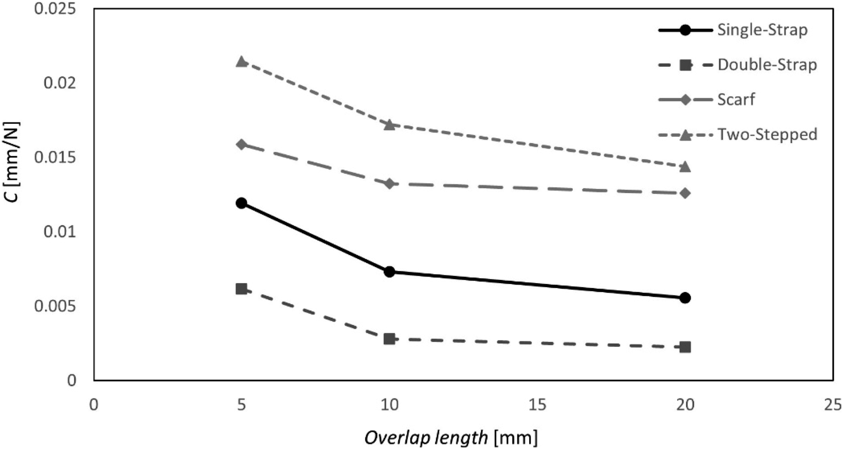
Figure 10 shows the overlap effects on strength when referring to upward bending. The corresponding values are detailed in Table 7. In terms of compliance, effects of the overlap length are demonstrated in Figure 11. Overlap effects on strength: upward bending. Detailed values on the overlap effects on strength: Upwards bending. Overlap effects on compliance: upward bending.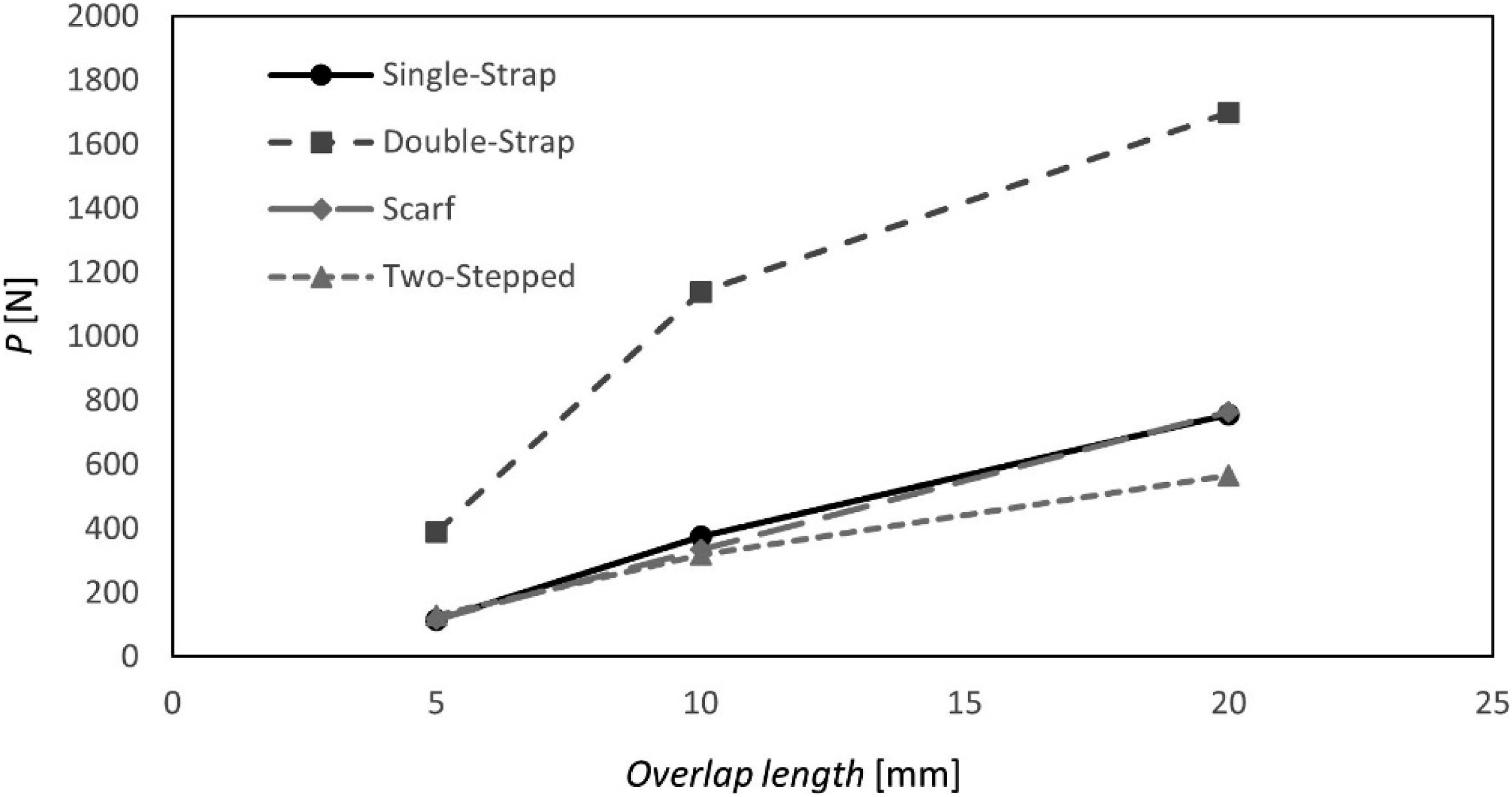
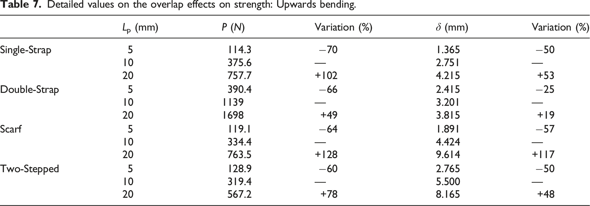
Observing the results, it is possible to understand the consequences of increments and reductions in the overlap length. For instance, the reduction in the overlap from the initially discussed 10 mm–5 mm lead to a similar impact in all of the repair systems, and it is represented by a reduction in the strength between 60-70%. Concerning the displacement at failure it represented a decrease of around 25% for the Two-Stepped and around 50% for the others.
On the other hand, the increase in the overlap size, from 10 to 20 mm, had a noticeable impact on the Scarf repair, since it presented an increment of 128% in its strength and 117% in displacement to failure. Still, it is also worth mentioning that due to the increase in the overlap, compared to the initial values, the second best improvement was noticed in the Single-Strap, where it doubled its strength and had an improvement of 50% regarding the displacement to failure.
The Double-Strap demonstrated the lowest values of compliance, for all overlap lengths that were tested. The Scarf repair seemed to be less affected, in terms of compliance, for changes in the overlap length, in comparison to tension and compression load conditions. Single-Strap and Two-Stepped repairs showed identical behaviours, related to the compliance variations for changes in the overlap length.
It is possible to verify that all types of repairs can be optimized using larger patches. However, when refereeing to the manufacturing, it is important to consider the limitation such as time, tools and space. For this reason, it was selected the best two in terms of improvement as being more appropriate to have overlaps of 20 mm, since one represents an easy implementation case, as the Single-Strap, and the other represents a more complex implementation, such as the Scarf repair, but with some advantages previously mentioned.
Load case 4: strength in downward bending
The strength was also studied in downward bending, whose P–δ curves are reported in Figure 12. P-δ curves for downward bending load case.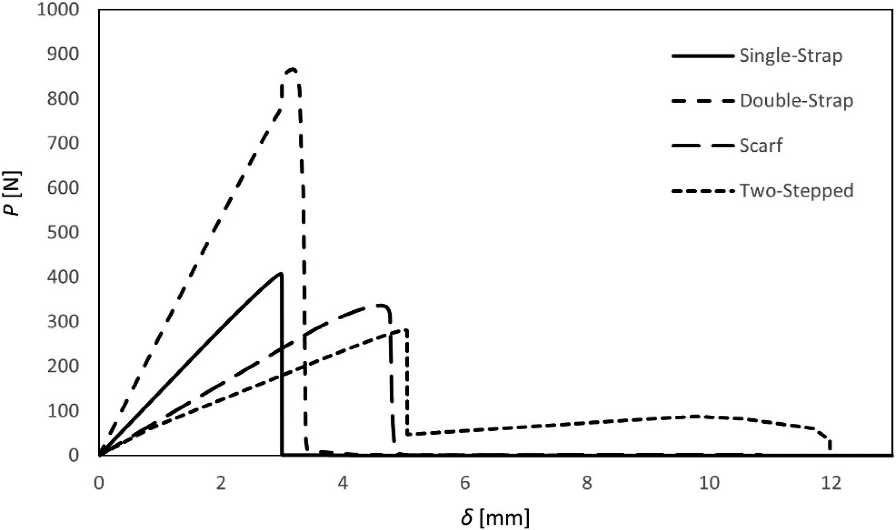
For the Single-Strap, results revealed a strength around 408 N, with a displacement of 2.98 mm. Peel stresses were lower when compared to the upward bending load case, regarding the same geometry. However, peel stresses at the adherend ends are still considerable, due to bending, and it is sufficient to provide a significantly lower strength when comparing to the behaviour presented under axial loadings. Related to the same phenomenon, the stiffness slightly decreased comparing to the upward bending, but the displacement level is still considerably low among other geometries.
Regarding the Double-Strap repair, a strength of 866 N was proved, with a displacement of 3.5 mm. Comparing to the Single-Strap, it is capable of sustaining a load that is more than 50% higher, being the displacement at failure 15% higher, revealing its superiority. Interestingly, the way the load is applied in downward bending allows a lower strength levels than the ones observed for upward bending. In fact, the peel stresses induced in the adhesive layer ends seemed to be more significant, due to higher bending moments. Increasing in strength usually inhibits premature failures, which explains the higher displacement carried by the Double-Strap compared to the Single-Strap.
Using a Scarf repair, the adhesive layer fails under 337 N, presenting 4.6 mm of bending displacement. In this loading case, there is an absence of a pull-out effect, as it was observed for under upward bending, however, only an increase in strength of 5% is registered comparing to that same loading case. The results are sufficient to ensure that the decreasing in the scarf angle allow an increase in strength, which is similar to what happened for other loading scenarios. An unsatisfactory level of strength provided by a scarf repair is also seen for this load case, being 17% and 61% lower comparing to Single-Strap and Double-Strap repairs, respectively. However, using a Scarf repair, the displacement at failure increased 35% and 24% comparing also to Single-Strap and Double-Strap, respectively. Oppositely to what happened for upward bending, a downward bending loading case provides a slightly higher level of stiffness, which can allow to conclude that the predominance of mode II loading in the Scarf adhesive layer tends to decrease the amount of displacement carried by the repair system.
It can be observed that the Two-Stepped suffered failure at the load of 281 N under a bending displacement of 5 mm. This geometry provides the lowest strength, being 68% lower than the one provided by the Double-Strap. This is justified by the strong peel stress levels found at the adherend ends of the vertical adhesive layers under downward bending. Despite of the predominance of mode II loading in the horizontal adhesive layers, which could be benefit in terms of mechanical behaviour, the vertical adhesive layers failed prematurely and the repair system lost a considerable amount of strength capacity. The prevalence of the horizontal adhesive layers provided a capability to the Two-Stepped repair to sustain a load of 86 N until 10 mm displacement, then failing at 32.4 N with 12 mm of displacement. The stiffness of the Two-Stepped is directly comparable to the stiffness provided by the Scarf repair, but with a lower strength, showing the clearly inferiority of this repair type among other repair configurations. Indeed, the use of Two-Stepped as a repair solution is totally unsuitable for downward bending loading. As it was mentioned for the upward bending, for downward bending, Double-Strap seemed to be the most suitable repair type, presenting the highest strength (more than 50% among all other repair types). Due to the implementing difficulties, already described above, and also due to aerodynamic efficiency, an embedded repair type can be preferred for some applications. In those cases, a Scarf repair should be used, and the characteristic angle should be decreased to an optimal and feasible value.
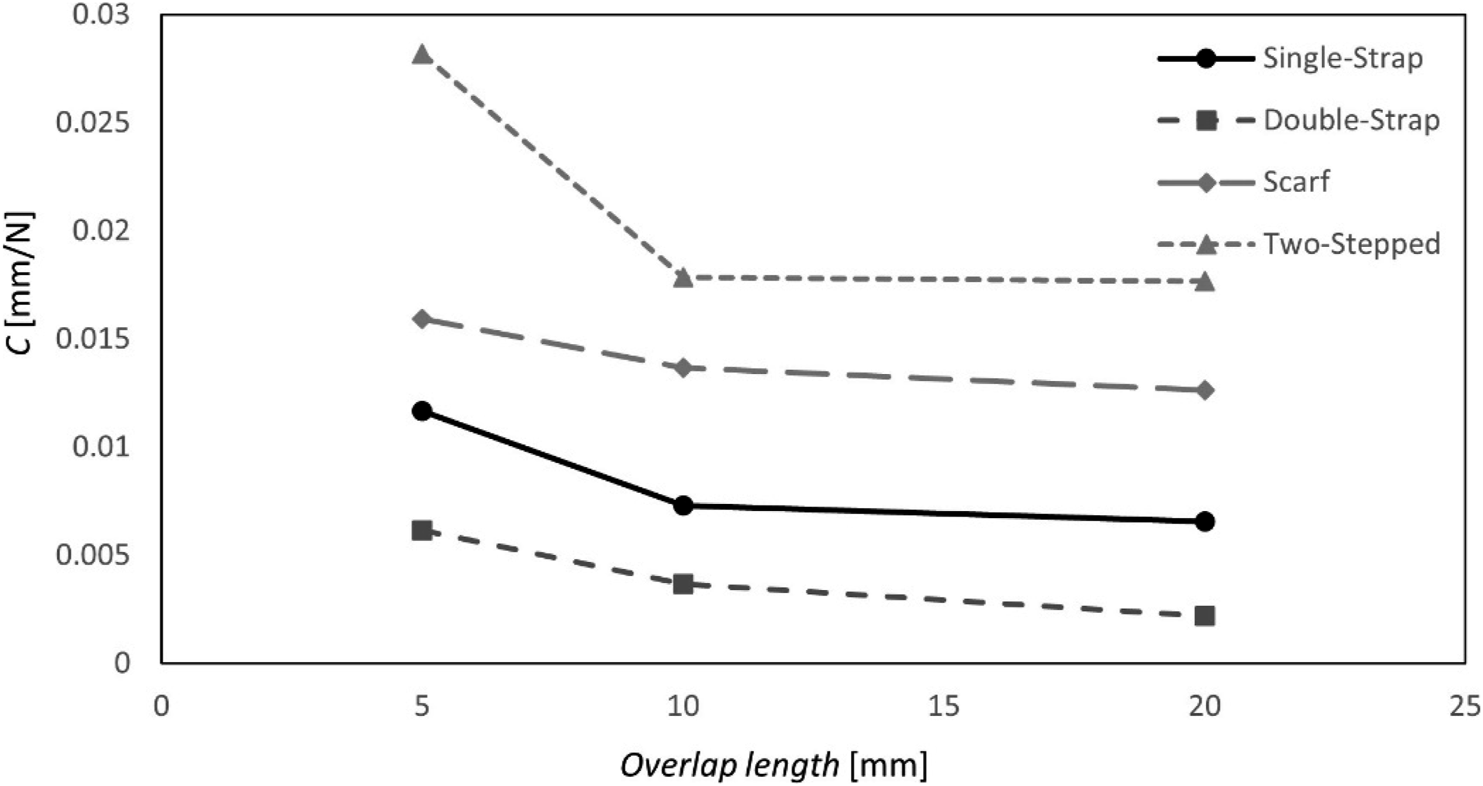
Figure 13 and Table 8 demonstrates the overlap length effect on the strength and displacement until failure. Compliance variations due to changes in the overlap length are demonstrated in Figure 14. Overlap effects on strength: downward bending. Detailed values on the overlap effects on strength: Downward Bending. Overlap effects on compliance: downward bending.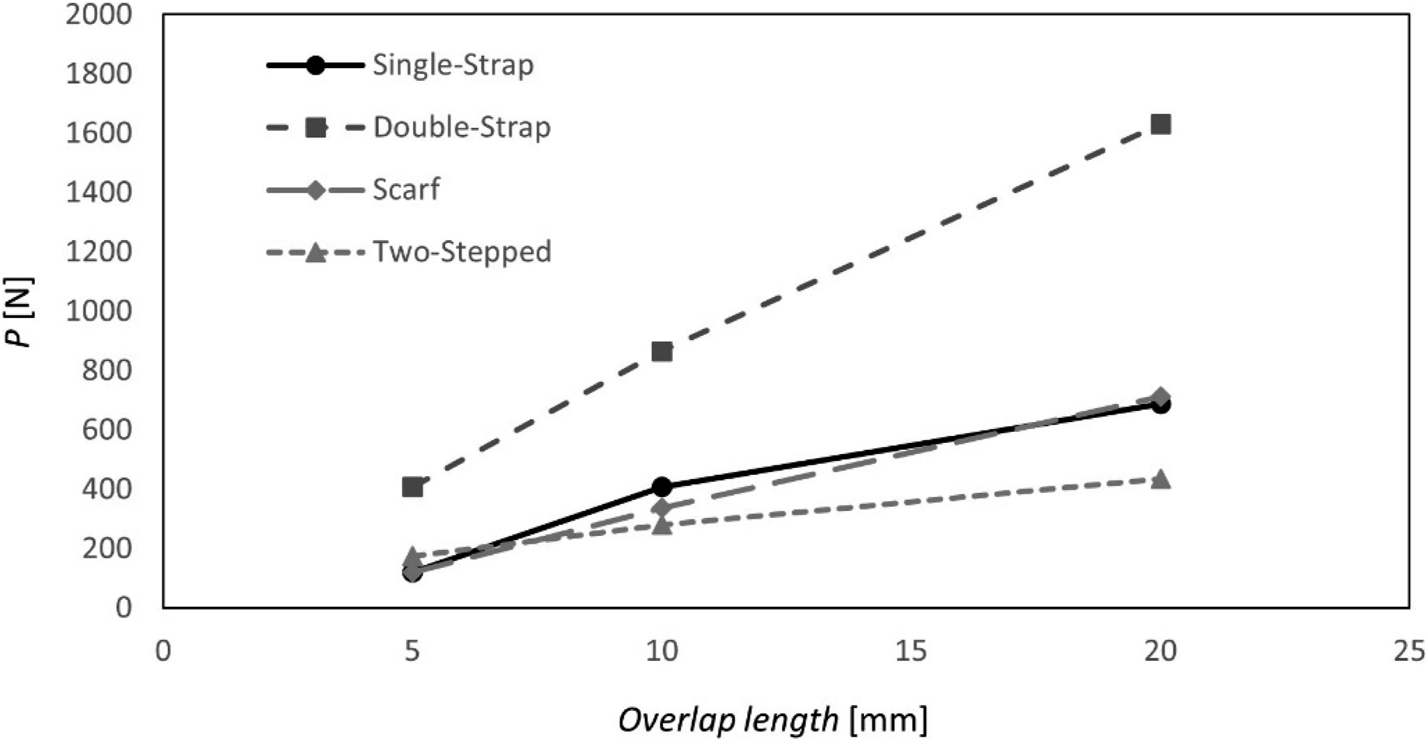
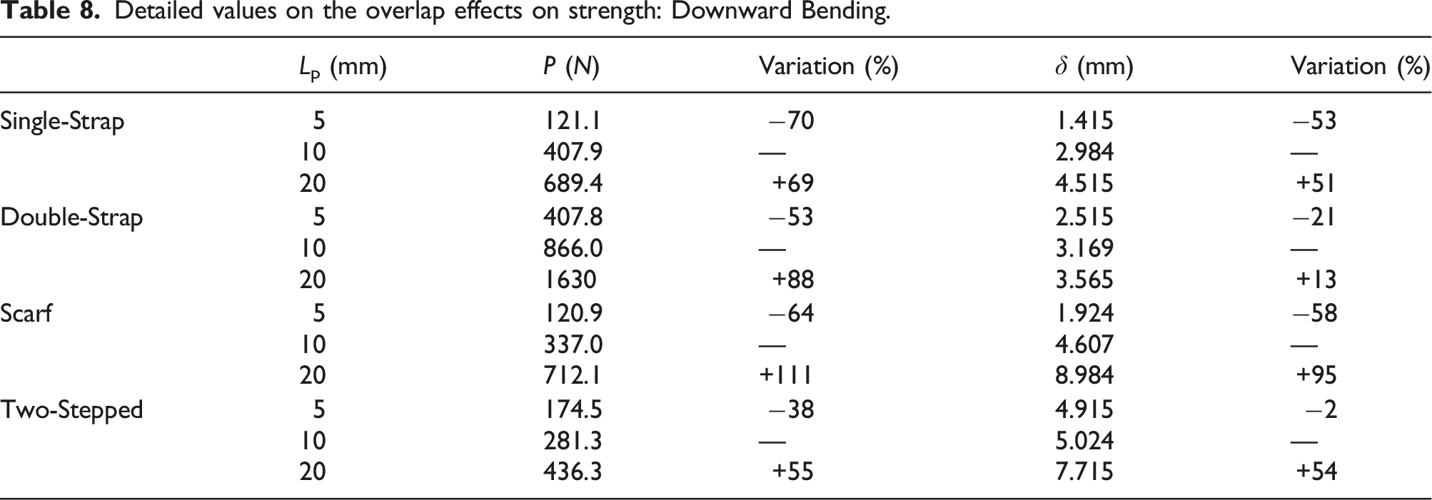
As it can be observed in Figure 10 and Table 8, the Scarf repair seems to have a linear variation of the failure load as well as the corresponding displacement with the increasing overlap length, which is the highest gain in the compared cases. The increasing tendency reduces when the overlap length increases from 10 to 20 mm on Single-Strap and Double-Strap repairs. The sustained load increased by 69% and 88%, respectively, from 10 to 20 mm. Hence, the Scarf repair demonstrates the highest gain in strength with the increasing overlap length of 111% while the Two-Stepped repair shows an increase of 55%. With the decreasing overlap length, the Two-Stepped repair shows the lowest loss of the sustained load (38%) while the Single-Strap preparation has the highest loss of the failure load (70%).
Similarly, to what happens in terms of strength, the displacement to failure related to the Scarf repair displays a linear variation with the increasing overlap length. The displacement associated to a Single-Strap repair is higher than that observed in a Scarf. The Double-Strap repair presents the lowest variation with the overlap length. Unlike the failure load, the failure displacement of the Two-Stepped repair appears to exhibit an increasing variation of the failure displacement when compared with the other types of repairs. Hence, in the instances where the failure load or the failure displacement are more concerned, the Scarf repair presents the best solution with the increasing overlap length. While in the specified cases where a lower overlap length has to be used, the Two-Stepped repair indicates the lowest loss of both strength and elasticity (38% and 2%, respectively).
The Two-Stepped showed the highest compliance for all the studied range of overlap lengths, under downward bending. For overlap lengths higher than 10 mm, the compliance is not significantly affected for this type of repair. The Double-Strap repair seemed to demonstrate the lowest values of compliance, despite of being the most influenced by changes in overlap length beyond 10 mm. The variation registered for the Single-Strap is identical to the one seen for the Double-Strap, while the variation observed for the Scarf repair is similar to the one verified for the Two-Stepped.
Failure path
The damage initiation mechanism seems to play an important role in the mechanical behaviour of a bonded repair, and the corresponding analysis helps to better understand the differences in strength between geometries and load cases. A careful description of the failure mechanism is explained presenting the stiffness degradation, as the damage parameter. The damage spectrum along the adhesive layer is related to catastrophic level of the failure. Failure paths are presented in this subsection, for each load case: The Load case 1: Failure in tension, Load case 2: Failure in compression, for tension, Load case 3: Failure in upward bending, Load case 4: Failure in downward bending, compression, upward bending, and downward bending, respectively.
Load case 1: Failure in tension
Figure 15 presents the failure path demonstrated by the studied four types of repair, under tensile loadings. Stiffness degradation (SDEG) for the tension load case: (a) Single-Strap, (b) Double-Strap, (c) Scarf, (d) Two-Stepped.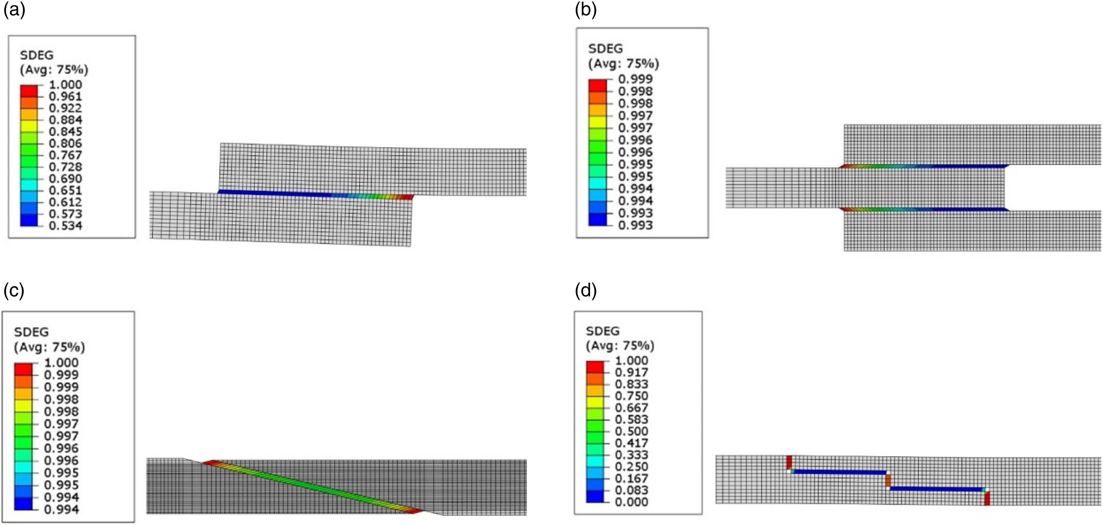
Analysing the Single-Strap repair at damage initiation, adhesive layer ends are fully degraded. At that moment, the outer ends are around 50% damaged. Consequently, the failure starts from the inner to the outer ends. The deformed shape demonstrates a forced bending, which is related to the failure path.
On the other hand, the Double-Strap demonstrated an approximately constant damage state before failure. In fact, the deformed shape is consistent with a tensile loading, not showing any forced bending. This failure path led to higher strength levels showed in Load case 1: Failure in tension, since the degradation seemed to be more distributed along the adhesive layer.
A considerable degradation distribution is also demonstrated in the Scarf repair, however not related with high strength. Despite of the absence of forced bending effects, the degradation is slightly more concentrated at the ends. As mentioned above, this distribution can be related with the percentage of mode I loading actuating in the adhesive layer, due to the characteristic angle. The amount of mode I loading for an angle approximately equal to 13.5° was sufficient to have approximately the same strength as the Single-Strap. The failure presented by the Scarf repair is more premature when compared to the failure seen in the Single-Strap, which is explained by the differences in stiffness presented in Figure 3. Moreover, from Figure 11, it can be stated that the failure of the Single-Strap repair is progressive (higher SDEG gradient), when compared to the failure observed in the Scarf repair.
The vertical adhesive layers are directly under pure mode I loading in the Two-Stepped, providing the failure initiation. Any damage is verified in the horizontal layers, before failure initiation. The support provided by these layers were sufficient to have a higher displacement at failure in comparison to a Scarf repair, as demonstrated in Load case 1: Failure in tension.
Load case 2: Failure in compression
Considering the compression load case, Figure 16 shows the corresponding failure paths. Stiffness degradation (SDEG) for the compression load case: (a) Single-Strap, (b) Double-Strap, (c) Scarf, (d) Two-Stepped.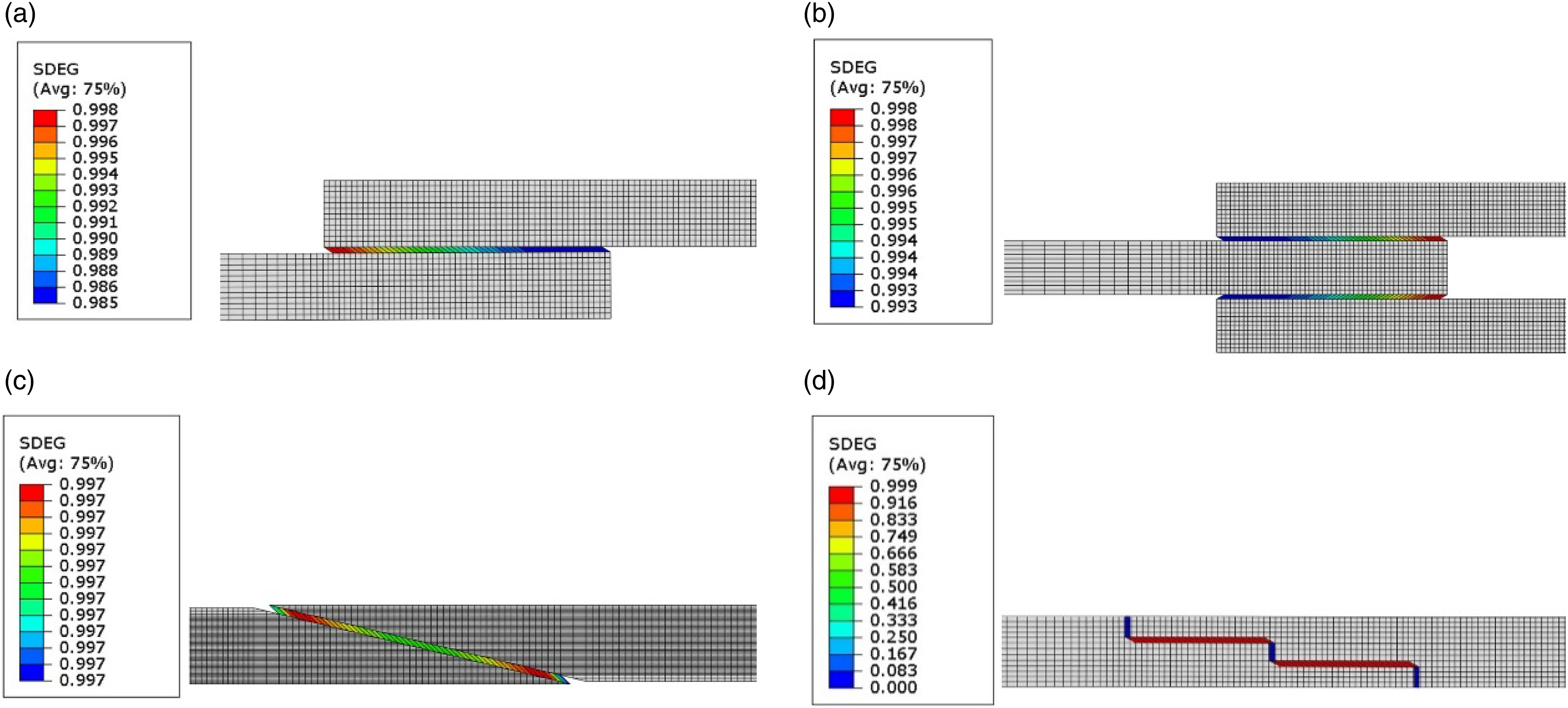
Under compression, the Single-Strap, in this case, exhibited a lower forced bending effect in comparison to the tension case, revealing a slightly more constant degradation state. At the moment of damage initiation, outer ends are fully degraded, while around 41% of the stiffness remained in the inner cohesive elements. Consequently, the failure initiates at the outer ends, propagating to the inner ends.
The failure path is identical to the previous one presented for the tension load case, so that similar strength and stiffness is verified, but the failure initiates at the inner ends. Damage occurs from the inner to the outer ends. Also, for this loading scenario, a distributed degradation state is verified.
A pull-out effect is registered in the Scarf repair, while being compressed. In fact, differently to what happened for the tension load case, the degradation state is almost the same. So, this geometry provides the most catastrophic failure within the analysed geometries and load cases. This premature failure behaviour explains the lowest displacement to failure presented by this type of repair in Figure 6, as well as the associated lower strength, comparing to other repair types.
The undamaged state of the vertical adhesive layers under pure compression on the Two-Stepped repair was proved in this stage, and it is related to the formulation of the cohesive zone model. The failure was considered to be induced by the degradation of the horizontal adhesive layers, making possible a higher strength level comparing to the tension load case, and also a competitive behaviour among other types of repairs under compression.
Load case 3: Failure in upward bending
Considering upward bending, the failure path for all types of repair are presented in Figure 17. Stiffness degradation (SDEG) for upward bending load case: (a) Single-Strap, (b) Double-Strap, (c) Scarf, (d) Two-Stepped.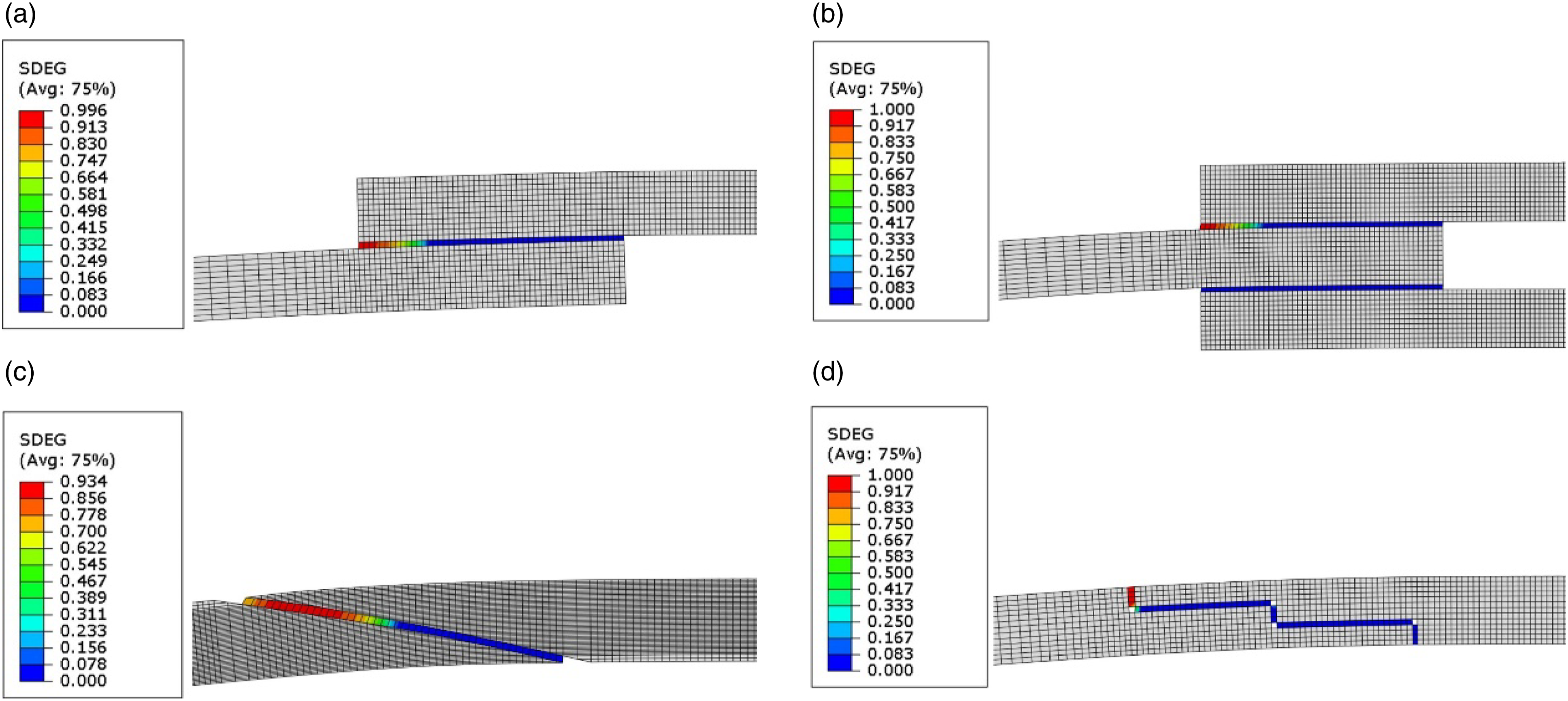
The nature of the loading scenario allowed a tensile state in the outer ends of the adhesive layer, being more prone to damage. At the moment of failure initiation, the inner ends are not degraded. Consequently, the failure occurs smoothly from the outer to inner ends. However, considering upward bending, outer ends seemed to be damaged earlier, in comparison to axial loading scenarios. This explains the aforementioned lower strength values.
Due to the load application, in a Double-Strap repair, the upper patch is strongly peeled. Consequently, a poor degradation distribution is seen in the upper adhesive layer when the outer ends failed precociously when compared to the inner ends. In fact, the lower patch seemed to not present any damage during the failure initiation. Consequently, the failure is driven by the disbond of the upper patch, failing from the outer to the inner ends. However, the lower patch are giving some kind of support, allowing a considerable increase in strength, which can be observed in Figure 9.
For Scarf repairs, in the opposite to what was verified under axial loads, the upward bending load provided a more concentrated damage state in the outer ends of the adhesive layer, being related to a lower strength. In fact, when the outer ends are completely damaged, any degradation is registered in the inner ends. Consequently, failure occurs from the outer to the inner ends.
Also in Two-Stepped repair, the damage is more concentrated in the outer cohesive elements. At the moment of damage initiation, those elements are the only ones being degraded. Failure propagates from the outer to the inner ends, following the adhesive layer path.
Load case 4: Failure in downward bending
Figure 18 demonstrates the failure paths under downward bending. Stiffness degradation (SDEG) for the downward bending load case: (a) Single-Strap, (b) Double-Strap, (c) Scarf, (d) Two-Stepped.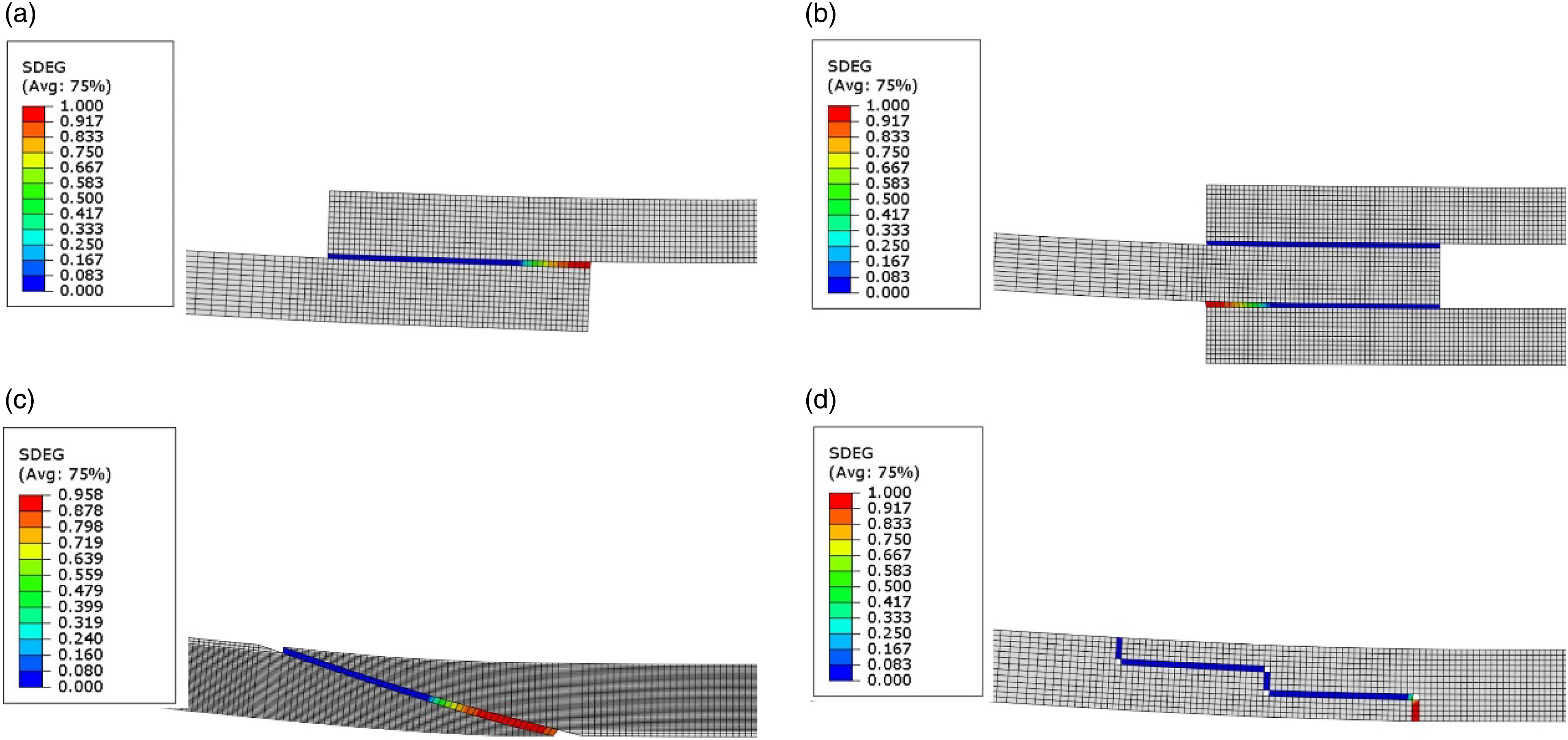
Considering the Single-Strap repair, the failure initiates at the inner adherend ends. The failure then propagates towards the outer cohesive elements. When the inner ends are damaged, any degradation state is captured in the outer ends. Consequently, damage is more concentrated, leading to lower strength levels, similarly to what was mentioned for the upward bending case.
The Double-Strap repair showed to have the highest strength and it is explained by the support given by the upper patch. Failure initiates when the outer cohesive elements of the lower adhesive layer is completely damaged. At that moment, any degradation is verified in the rest of the adhesive layer. Lower patch disbond occurs when the failure is then propagated to the inner ends. While cohesive failure does not occur in the upper adhesive layer, it is giving support explaining the higher aforementioned strength, in Load case 4: Failure in downward bending.
The failure paths presented by Scarf and Two-Stepped repairs are symmetric to the ones shown under upward bending. In this way, on both repairs, failure initiates at the inner ends. Damage concentration is more pronounced in the Two-Stepped repair, in comparison to the Scarf. In both cases, the failure is propagated from the inner to the outer ends, following adhesive layer path.
Conclusions
The use of repairs in aeronautical structures has been very widespread over the years. However, with the continuous increase of composite material structures, the study and optimization of these repairs is a very important factor to minimize the number of maintenance actions, cost of materials and durability of the air-frame, which also reflects in the time the aircraft is not operating, thus bringing costs to the company. A cohesive zone model was implemented in FE models, in order to predict strength and displacement to failure, and compliance in different types of repair (Single-Strap, Double-Strap, Scarf, and Two-Stepped), considering four different loading scenarios (tension, compression, upward bending, and downward bending). In addition, failure paths were also accessed, being related to the demonstrations of strength. The following conclusions were obtained for the strength prediction: • Double-Strap is capable to sustain the highest loads among all other types of repair. However, its implementation is difficult in most of the applications. • Scarf or Two-Stepped repairs are preferable for aerostructural applications. The corresponding choice depends on the level of displacement needed, having similar strengths. Two-Stepped showed to carry higher amounts of displacement for all the studied load cases. There is an exception for the compression load case. In that condition, Two-Stepped almost reaches the same strength as the one provided by the Double-Strap, being the most promise geometry under compression. These two types of repair should be optimized: the Scarf in terms of the characteristic angle, and the Two-Stepped in terms of the number of steps. • Failure paths explained the differences observed in strength. Higher bending effects provided higher peel stress concentrations at the adherend ends, decreasing strength. This explains the lower strength observed under upward bending and downward bending. • Under compression, the failure showed to be more catastrophic when compared to tension load cases, and this is related to the inhibition of secondary bending effects in some geometries. Particularly, a pull-out effect is seen in a Scarf repair, which can induce a premature failure. Also under compression, the Two-Stepped repair demonstrates shear in the horizontal adhesive layer while the failure is initiating. However, under tension, the vertical adhesive layers are subjected to peel loading, being responsible for a strength decreasing. • The effect of the bending moment, and upward and downward bending, and how it induces peel stresses was clearly demonstrated. In this way, the upper and lower adhesive layers are responsible for failure initiation in upward and downward bending, respectively. • If a saturation on the effect of the overlap in strength, displacement, and compliance is verified, lengths higher than 10 mm should not be used, maintaining manufacturing facilities. Generally, Scarf repair presented a highest potential on improving properties by increasing the overlap length, and an optimal value for the characteristic angle is possible to determine according to the literature.
Footnotes
Declaration of conflicting interests
The author(s) declared no potential conflicts of interest with respect to the research, authorship, and/or publication of this article.
Funding
The author(s) disclosed receipt of the following financial support for the research, authorship, and/or publication of this article: This work was supported by the LaboratÃ&z.hfl;Â3rio Associado de Energia, Transportes e AeronÃ&z.hfl;¡utica (LAETA) (UIDB/50022/2020); FundaÃ&z.hfl;§Ã&z.hfl;£o para a CiÃ&z.hfl;Âancia e a Tecnologia (FCT) (2022.03149.CEECIND).