
Abstract
Here we introduce compliant mechanisms that can be triggered using bistable switches to achieve two different states of stiffness (i.e., high and low stiffness) along multiple degrees of freedom The compliant mechanisms leverage principles of constraint manipulation and stiffness cancelation to achieve these binary states with a stiffness difference as large as an order of magnitude. Although these principles have been used in prior works to achieve binary stiffness in compliant mechanisms that achieve a single degree of freedom (DOF) (e.g., a single translation or a single rotation), this work advances the theory to achieve binary stiffness in compliant mechanisms that achieve multiple DOFs. Specifically, two designs are introduced, fabricated, and tested to demonstrate binary stiffness in two DOFs. The first design achieves binary stiffness along two orthogonal translational DOFs and the second design achieves binary stiffness about two orthogonal rotational DOFs with intersecting axes.
Keywords
Introduction
Mechanical systems that achieve actively tunable stiffness are desirable for numerous applications. Such applications include robots that mimic the adaptable stiffness capabilities found in nature for effectively responding to changing ambient conditions,1–5 sensors and actuators that tune stiffness to customize their sensitivity and resolution, 6 vibration isolators that adapt their resonant frequencies to filter out targeted vibrations,7,8 and medical devices that can be made compliant to achieve safe human interactions but then can be made stiff to withstand force applications as necessary. 9
The principles underlying how a mechanical system’s stiffness can be tuned vary dramatically. 10 Magnetic and electric fields have been used to actively tune the stiffness of magnetorheological11–13 and electrorheological 14 elastomers by manipulating magnetic or electrically active particles suspended within a polymeric matrix. Electro-bonded laminates that utilize principles of friction 15 and other electrically heated laminates that respond to changes in temperature 16 have been used to tune the bending stiffness of beams. Electricity has also been used to actively change the phase of certain materials from a solid to a liquid within a composite to dramatically change the composite’s stiffness.17,18 The concepts of granular 19 and layer 20 jamming have also been used to control the stiffness of various mechanical systems. This concept utilizes the fact that particles or sheets of materials that are loosely packed together can freely slide past each other, but when they are forced together (usually by drawing a vacuum) the overall structure becomes substantially stiffer due to the high-friction interactions between its closely packed particles or sheets. Mechanical systems can also use actuators and sensors to achieve stiffness tunability via closed-loop mechatronic control.21,22 The stiffness of a beam can also be changed by effectively shortening its length by pinching or pressing against it.7,23,24
Stiffness-tuning approaches that rely predominantly on deformation, however, are favorable for tuning the stiffness of compliant mechanisms 25 since such approaches do not compromise the benefits inherent to such mechanisms (i.e., high precision, friction free, no backlash, minimal-to-no assembly required, easy to fabricate, lightweight, and low cost). Many such approaches require flexible elements to deform a certain amount before they make contact with hard stops, 26 appreciably strain stiffen, 27 or buckle 28 to change the mechanism’s stiffness a significant amount. Some approaches use actuated deformation to attach additional flexible elements on a compliant system’s stage to stiffen it 29 while other approaches fold or curve flexible elements for the same purpose. 30
One of the most promising deformation approaches for tuning a compliant system’s stiffness over an extreme range utilizes the principle of stiffness cancelation. Stiffness cancelation occurs when flexible elements that exhibit positive stiffness are arranged in parallel with flexible elements that exhibit negative stiffness.31–33 When these stiffnesses are such that they fully cancel out and the resulting system’s force-displacement profile exhibits a range of displacement over which zero force is required (i.e., the system’s potential strain energy is constant), the system is said to be statically balanced34–38 and zero stiffness 39 is theoretically achieved. A variety of system’s have had their stiffness tuned over an impressively large range by adjusting the preload of a negative-stiffness element by deforming it so that the system is changed from exhibiting a large positive stiffness to exhibiting a near-zero stiffness in a statically balanced state.40–43 Some compliant mechanisms44–48 have employed the principle of bistability49–51 to preload the negative-stiffness element between two stable states of deformation so the mechanism achieves binary stiffness (i.e., two states of stiffness—high and low) in this way. All of these compliant mechanism examples are, however, planar mechanisms that achieve binary stiffness along a single DOF only (e.g., a translation or a rotation).
Inspired by such mechanisms,
48
this work introduces spatial compliant mechanisms that leverage similar principles to achieve binary stiffness along multiple DOFs by triggering a single bistable switch. Two example designs are shown in Figure 1. The first design achieves binary stiffness along two orthogonal translational DOFs (see Supplementary Video 1). The design’s stiff state is shown in the photo of Figure 1(a) and its compliant state is shown in the photo of Figure 1(b) with its bistable switch popped inward (i.e., triggered). Note that although the design achieves two translational DOFs (i.e., two independent directions of allowable displacement), it also achieves every combination of those translations as depicted by the disk of black arrows shown in Figure 1(b). This disk represents all the directions in which the mechanism’s stage could freely translate. The second design achieves binary stiffness along two orthogonal rotational DOFs with intersecting axes (see Supplementary Video 2). The design’s stiff state is shown in the photo of Figure 1(c) and its compliant state is shown in the photo of Figure 1(d) with its bistable switch triggered. Note that although the design achieves two rotational DOFs (i.e., tip and tilt), it also achieves every combination of those rotations as depicted by the disk of red rotational axes shown in Figure 1(d). This disk represents all the axes about which the mechanism’s stage can freely rotate. A binary-stiffness compliant mechanism that achieves two translational degrees of freedom (DOFs) shown in its (a) stiff and (b) compliant state with its switch triggered. Another binary-stiffness compliant mechanism that achieves two rotational DOFs shown in its (c) stiff and (d) compliant state with its switch triggered.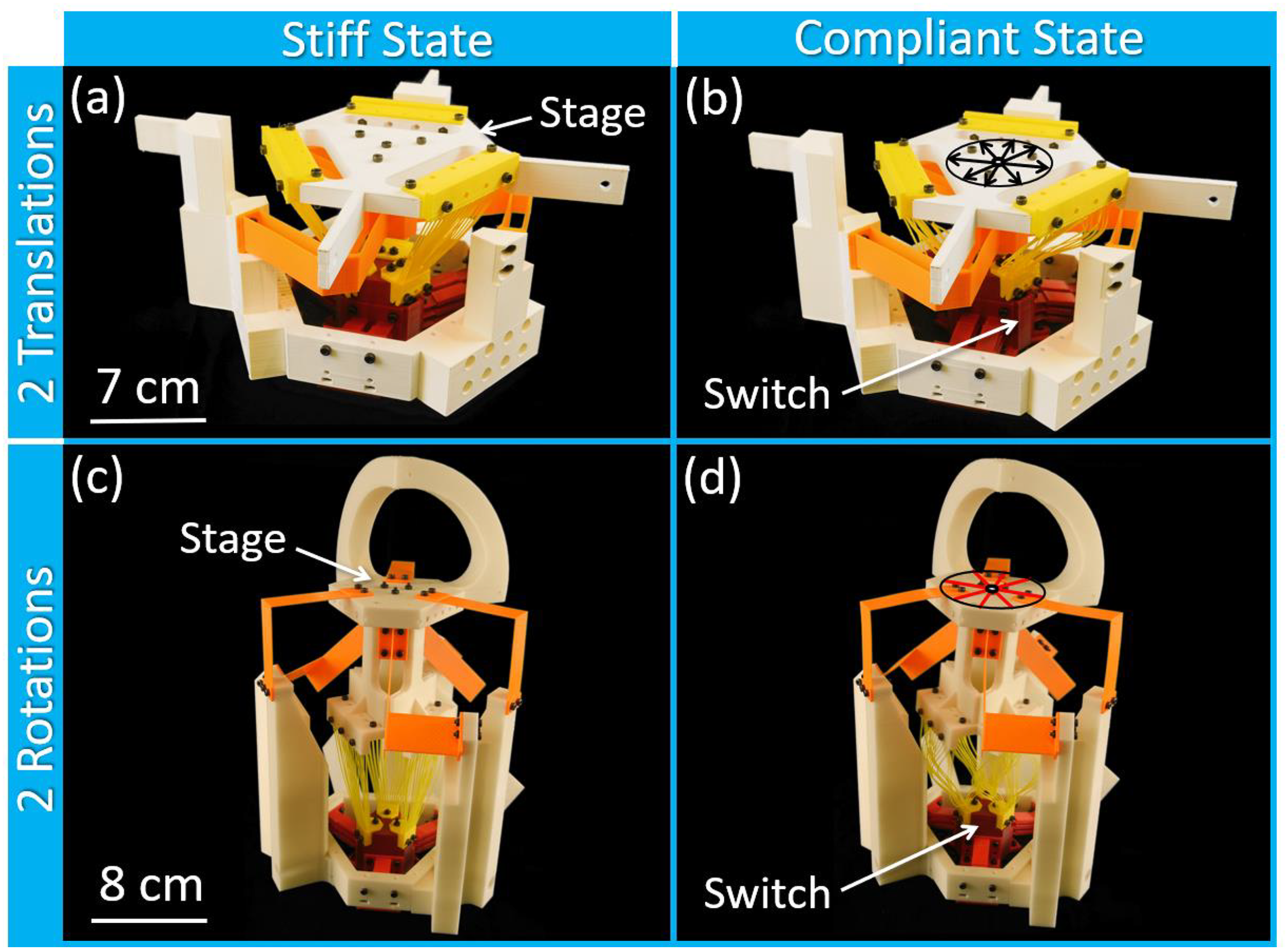
Both compliant mechanism designs enable a number of applications. If the design of Figure 1(a) and (b) was arrayed side by side within a large two-dimensional lattice, a metamaterial would emerge that could be actuated with different combinations of triggered switches to achieve a multitude of stiffness states along multiple directions within the plane of the lattice. The design of Figure 1(c) and (d) could be used as a resonant tip-tilt mirror with natural frequencies that could be changed to tune the mirror’s passive scanning speed on demand. Both designs could be used as energy harvesters that could be tuned to optimally collect energy from ambient vibrations of different frequencies. They could also be used as mechanical transistors that allow stress waves to pass through them along both of their DOF axes when their switches are triggered but that restrict the passage of stress waves when their switches are not triggered. The mechanisms could also be used as multi-axis precision motion stages that can be tuned to accommodate different actuators and sensors to increase or decrees resolution and sensitivity. Moreover, they could be used as lockable joints within robots that can be triggered to permit the desired DOFs with high compliance on demand.
This work explains how the two compliant mechanisms introduced in Figure 1 achieve binary stiffness along both of their two DOFs using principles of constraint manipulation and stiffness cancelation. It provides fabrication details and experimental measurements that demonstrate how drastically the stiffness values drop from a high state to a low state along both DOFs after each mechanism’s bistable switch is triggered. Data is also provided pertaining to the repeatability of each mechanism’s switch.
Constraint synthesis and manipulation
This section discusses how the designs of Figure 1 were synthesized so that their flexible element constraints successfully permit their intended DOFs while restricting motion in all other directions. It also explains how the constraints are manipulated when each mechanism’s switch is triggered to contribute to the effect of binary stiffness along each DOF.
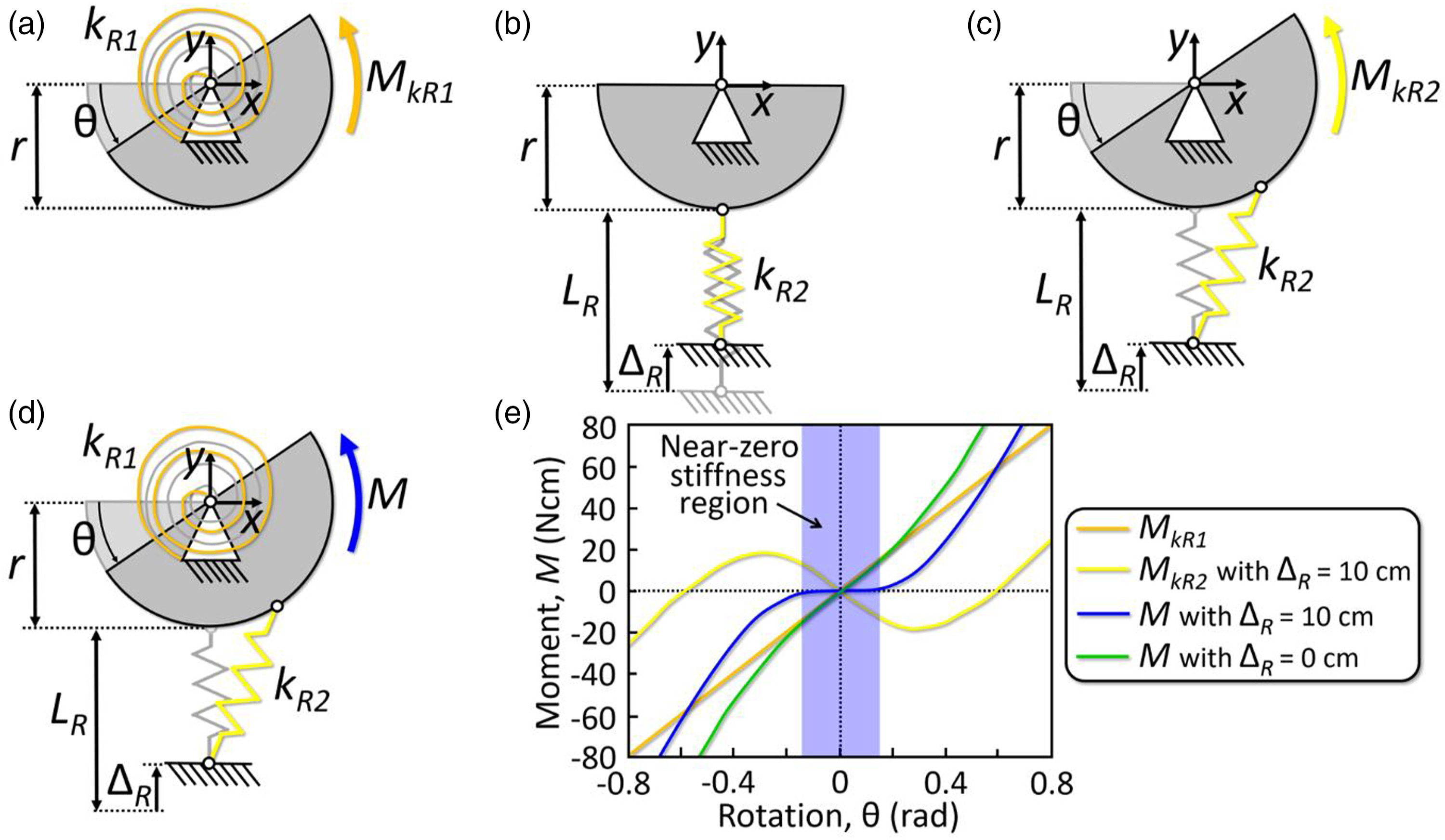
The flexible element constraints of both compliant mechanisms of Figure 1 were synthesized using the freedom and constraint topologies (FACT) approach.52–54 This approach leverages a comprehensive library of geometric shapes, called freedom and constraint spaces, that guide designers in synthesizing the flexible elements of a compliant mechanism to achieve a desired set of DOFs. Freedom spaces represent all the ways a compliant mechanism is permitted to deform with high compliance (i.e., the combination of every DOF). The disks of translations and rotations in Figure 1(b) and (d) respectively are examples of freedom spaces. Constraint spaces are complementary to freedom spaces in that they represent all the ways that flexible elements can be located and oriented to achieve the permissible deformations of the freedom space. Thus, the FACT approach directly links desired DOFs to freedom spaces, which in turn link to complementary constraint spaces. Designers then use constraint spaces to synthesize flexible elements to achieve the desired DOFs.
The flexible elements within the design of Figure 1(a) and (b) are categorized as three types–flexure bearings, tuning springs, and bistable switch elements (Figure 2). The flexure bearings, shown orange in Figure 2(a), consist of three axisymmetric limbs of serially stacked pairs of parallel blade flexures. When attached to the stage, the flexure bearings permit the translations of the freedom space, shown as a disk of black arrows in Figure 2(a), while stiffly constraining all other directions. Similar parallel-blade-flexure-based topologies have been used in other mechanisms to achieve two translational DOFs as well.55–57 The tuning springs, shown yellow in Figure 2(b), consist of angled wire flexures that lie on parallel planes. Three pairs of these parallel planes of wire flexures are arranged in an axisymmetric way to directly join the mechanism’s stage to its bistable switch as shown. When the wire flexures of the tuning springs are undeformed, their freedom space is empty (i.e., the wire flexures constrain the stage so that it cannot freely deform in any direction). The bistable switch elements, shown red in Figure 2(b), consist of three axisymmetric sets of parallel but angled flexible elements that join the switch to the mechanism’s fixed ground. Similar bistable switch designs have been used for other spatial mechanism scenarios.
58
When the flexible elements of the bistable switch of Figure 2(b) are angled down as shown, their freedom space is also empty. Thus, when all the flexible element components are combined within the full mechanism of Figure 2(c), the stage achieves no DOFs according to the constraint assumptions of the FACT approach. When, however, the mechanism’s bistable switch is triggered inward so that its flexible elements stably remain angled up even after the triggering force is removed, the wire flexures of the tuning springs buckle and curve outward as shown in Figure 2(d). Note that the wire flexures are all fabricated with a slight curvature to begin with so that when they buckle, they do so in a controlled way. According to the FACT approach, once the wire flexures are appreciably curved after buckling,
59
they fail to provide any constraint to the mechanism’s stage and thus the stage achieves six DOFs—three translations shown as black arrows in Figure 2(d) and three rotations shown as red lines with circular arrows about their axes. Thus, when all the flexible element components are combined within the full mechanism of Figure 2(e) and (f) with the switch triggered inward, the only constraint imposed on the stage is from the orange flexure bearings of Figure 2(a). Thus, the stage can freely displace along the two translational DOFs shown as black arrows in Figure 2(e) and (f) including all other translational motions shown as arrows in the disk of Figure 2(a). Thus, by triggering the bistable switch inward and then back out again, the flexible element constraints of the mechanism of Figure 2 are manipulated (i.e., displaced and deformed) such that the stiffness values along the intended translational DOFs drop and then rise again respectively to achieve the desired binary stiffness capabilities. A description of the flexible element constraints that constitute the binary-stiffness compliant mechanism design that achieves two translational DOFs. (a) The design’s flexure bearings guide all translations within the freedom space disk of black arrows. (b) Together the undeformed tuning springs and bistable switch elements constrain the mechanism’s stage with no DOFs. (c) Thus, all the flexible elements combined constrain the stage to achieve no DOFs until (d) the switch is triggered inward and the tuning springs curve outward and thus lose their constraint capabilities so that the mechanism achieves (e), (f) the two translational DOFs of its flexure bearings.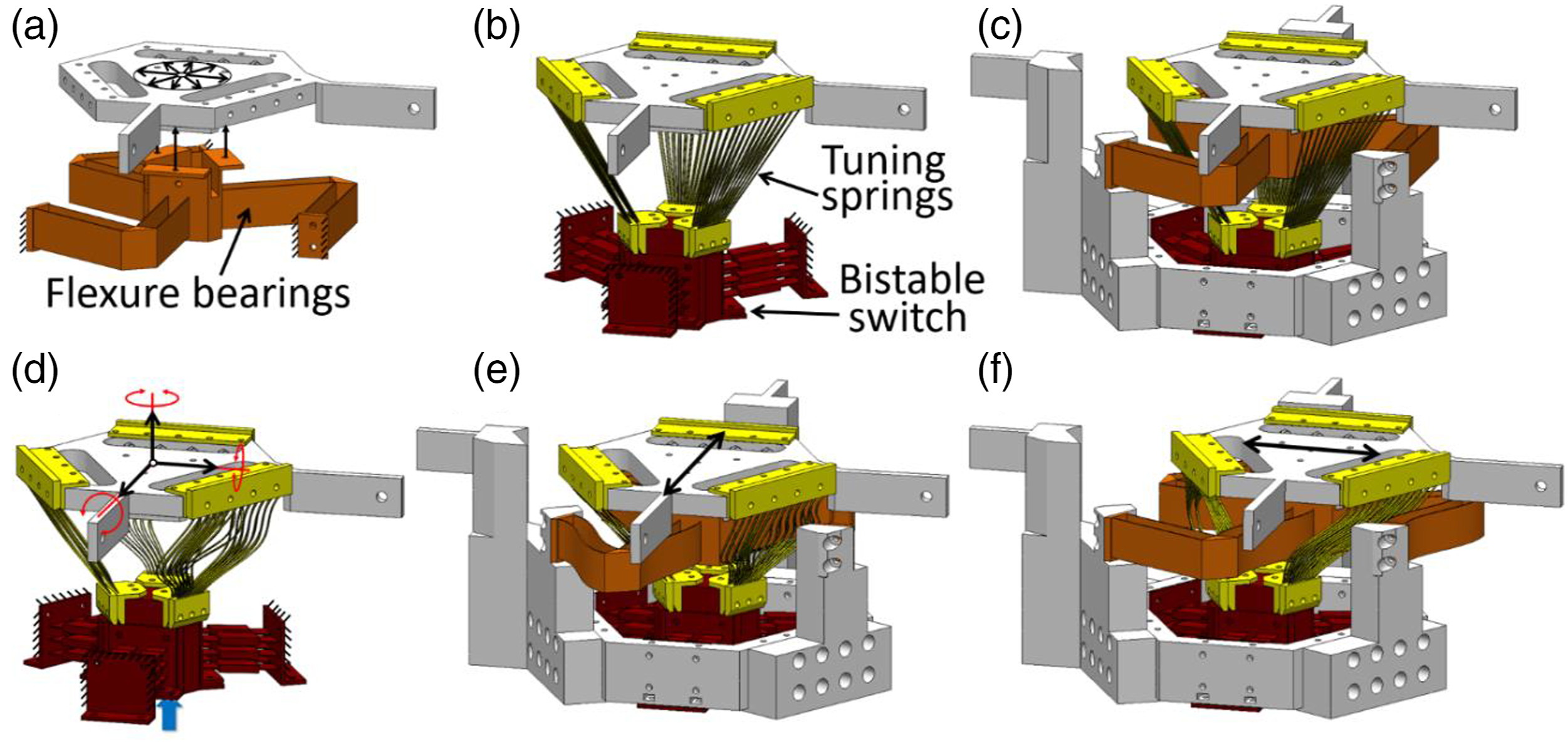
The flexible elements within the design of Figure 1(d) and (c) are also categorized as three types–flexure bearings, tuning springs, and bistable switch elements (Figure 3). The flexure bearings, shown orange in Figure 3(a), consist of three axisymmetric copies of two different kinds of bent-blade flexures (a.k.a. folded leaf spring flexures).60–62 When attached to the stage, the flexure bearings permit the rotations of the freedom space, shown as a disk of red rotational axes in Figure 3(a), while stiffly constraining all other directions. According to the complementary constraint space of this freedom space,52–54 it’s important that the crease lines of the bent blades, shown as blue lines in Figure 3(a), either lie on the same plane as the freedom space disk or intersect its center point as shown. Other compliant mechanism topologies have been designed to achieve the same two DOFs but using different flexible elements.63–65 The tuning springs, shown yellow in Figure 3(b), consist of angled wire flexures that lie on parallel planes. Three pairs of these parallel planes of wire flexures are arranged in an axisymmetric way to directly join the mechanism’s stage to its bistable switch as shown. When the wire flexures of the tuning springs are undeformed, their freedom space is empty (i.e., the wire flexures constrain the stage so that it cannot freely deform in any direction). The bistable switch elements, shown red in Figure 3(b), consist of three axisymmetric sets of parallel but angled flexible elements that join the switch to the mechanism’s fixed ground. When these elements are angled down as shown, their freedom space is also empty. Thus, when all the flexible element components are combined within the full mechanism of Figure 3(c), the stage achieves no DOFs according to the constraint assumptions of the FACT approach. When, however, the mechanism’s bistable switch is triggered inward so that its flexible elements stably remain angled up even after the triggering force is removed, the wire flexures of the tuning springs buckle and curve outward as shown in Figure 3(d). Note that these wire flexures are also fabricated with a slight curvature to begin with so that when they buckle, they do so in a controlled way. Once the wire flexures are appreciably curved after buckling, they fail to provide any constraint to the mechanism’s stage and thus the stage achieves six DOFs—three translations shown as black arrows in Figure 3(d) and three rotations shown as red lines with circular arrows about their axes. Thus, when all the flexible element components are combined within the full mechanism of Figure 3(e) and (f) with the switch triggered inward, the only constraint imposed on the stage is from the orange flexure bearings of Figure 3(a). Thus, the stage can freely rotate about the two rotational DOFs shown as red lines with circular arrows about their axes in Figure 3(e) and (f) including all other rotational motions shown as red lines in the disk of Figure 3(a). Thus, by triggering the bistable switch inward and then back out again, the flexible element constraints of the mechanism of Figure 3 are manipulated such that the stiffness values about the intended rotational DOFs drop and then rise again respectively to achieve the desired binary stiffness capabilities. A description of the flexible element constraints that constitute the binary-stiffness compliant mechanism design that achieves two rotational DOFs. (a) The design’s flexure bearings guide all rotations within the freedom space disk of red lines. (b) Together the undeformed tuning springs and bistable switch elements constrain the mechanism’s stage with no DOFs. (c) Thus, all the flexible elements combined constrain the stage to achieve no DOFs until (d) the switch is triggered inward and the tuning springs curve outward and thus lose their constraint capabilities so that the mechanism achieves (e), (f) the two rotational DOFs of its flexure bearings.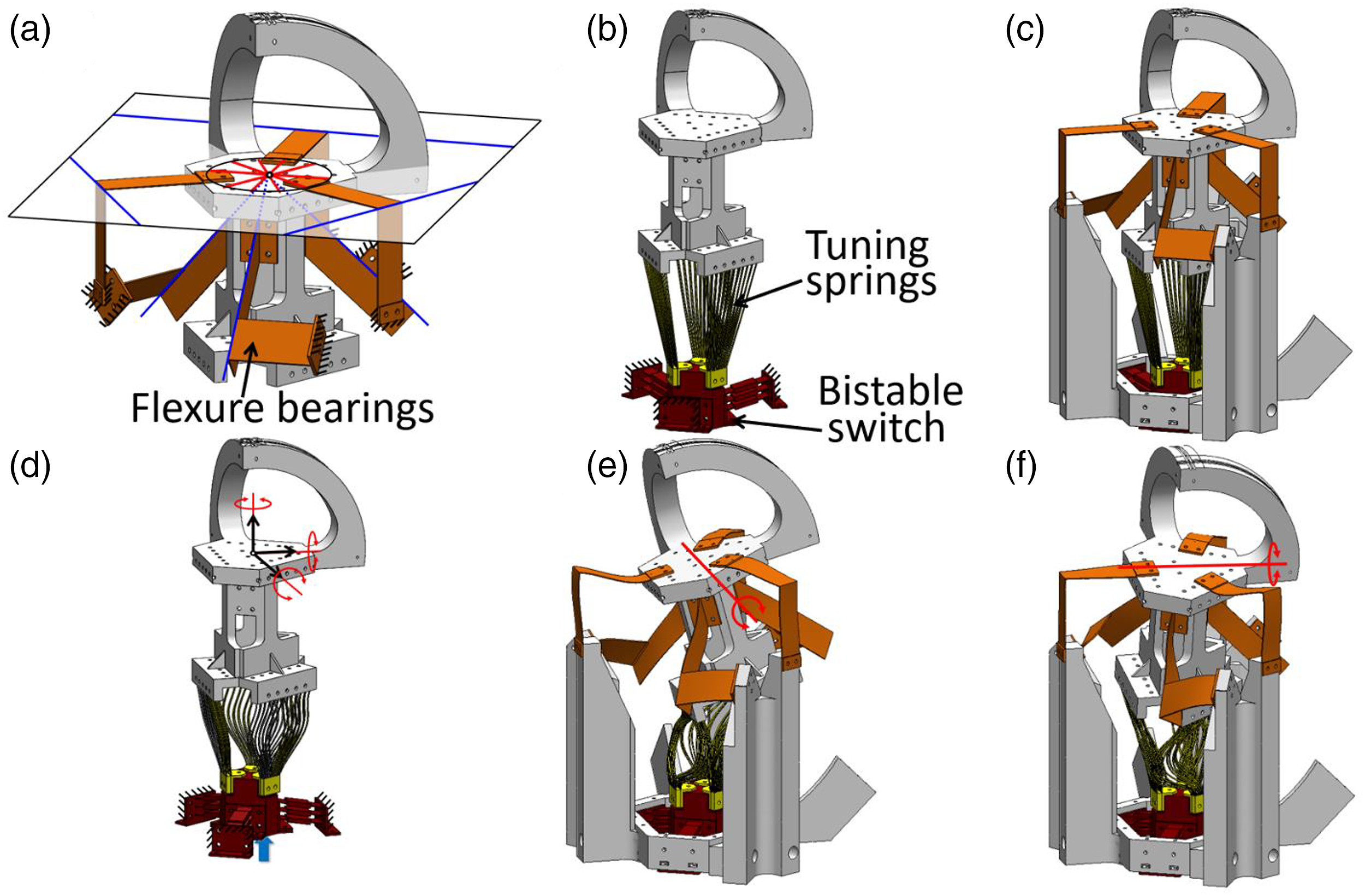
Stiffness cancelation
This section explains how the binary-stiffness compliant mechanism designs of Figures 2 and 3 use principles of stiffness cancelation to achieve dramatic changes in stiffness when their switches are triggered. Single-axis examples, which use linear springs (i.e., springs that exhibit a constant stiffness regardless of how much they are deformed), are studied as simplified planar translational and rotational analogs of the sophisticated spatial mechanisms of Figures 2 and 3 respectively.
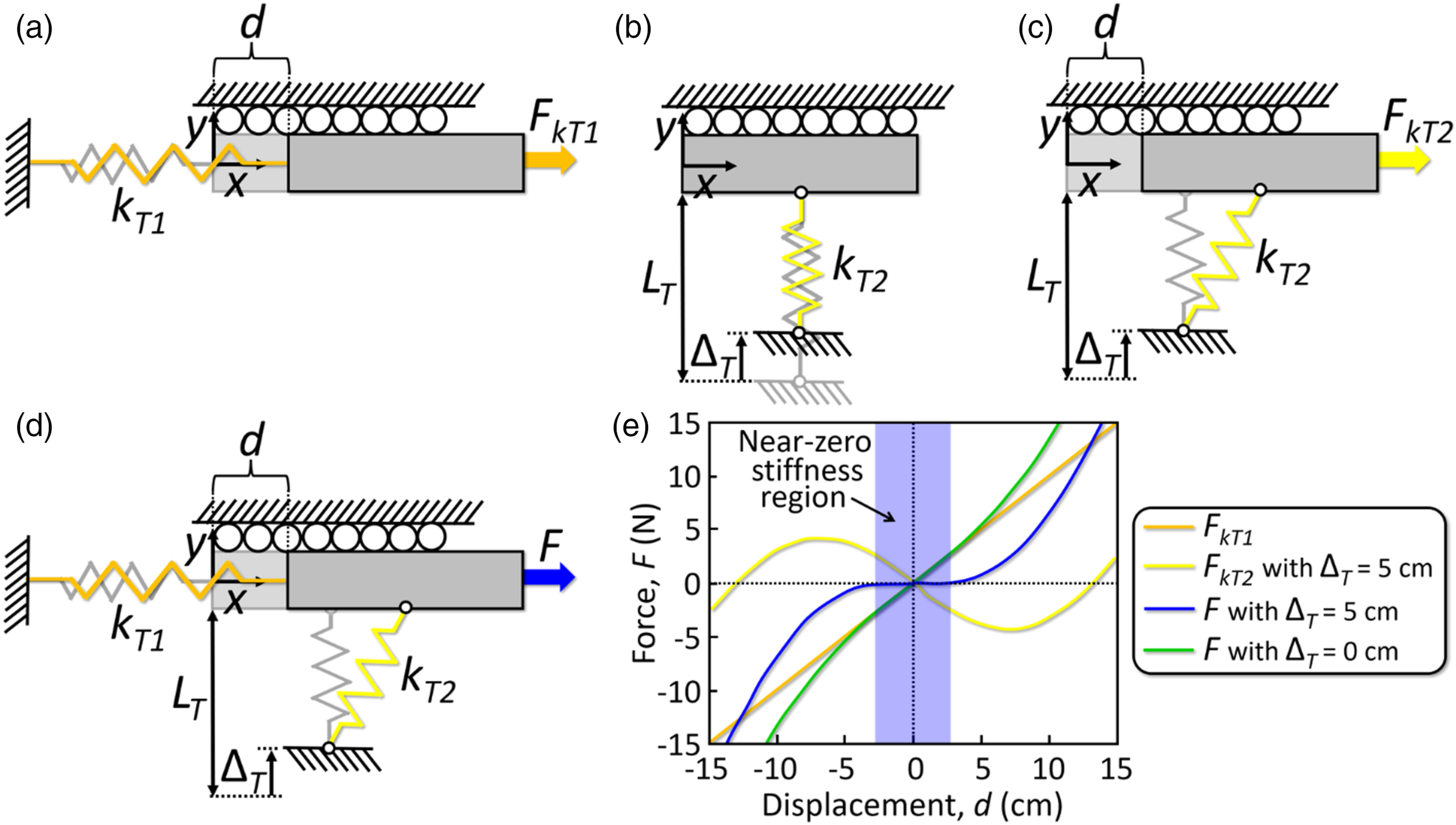
Consider first the simplified translational example of Figure 4(a)–(e) to understand how the mechanism of Figure 2 achieves binary stiffness along its two translational DOFs due to stiffness cancelation. If the rigid rectangular stage of Figure 4(a) is joined to a fixed ground by a linear spring with a stiffness of kT1 = 1 N/cm and the stage is constrained by rollers to only translate in a single direction with a displacement of d, the system’s force-displacement plot that would result from loading the stage with a force, FkT1, would be the orange line plotted in Figure 4(e) according to (a) Schematic of a rectangular stage attached to a positive-stiffness spring. (b) The stage attached to a preloaded negative-stiffness spring. (c) The preloaded system’s stage being displaced by a force FkT2. (d) The stage attached to both the positive and the negative-stiffness springs being displaced by a force, F. (e) Different scenario force-displacement plots that demonstrate how much the stiffness of the system of part (d) can be tuned by adjusting the preload displacement, Δ
T
.

Now consider removing the spring of Figure 4(a) and attaching a different linear spring to the stage with an undeformed length of L
T
= 20 cm and a stiffness of kT2 = 3 N/cm, as shown in Figure 4(b). If the new spring is preloaded by displacing its fixed end inward an amount, Δ
T
= 5 cm, and the stage is only allowed to translate in the direction perpendicular to the preload with a displacement of d, the system’s force-displacement plot that would result from loading the stage with a force, FkT2, according to Figure 4(c) would be the yellow line plotted in Figure 4(e) according to
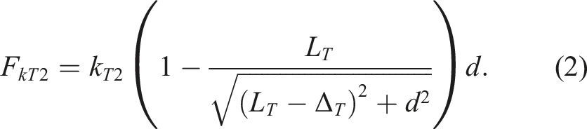
If the same preloaded-spring scenario is then repeated but the spring of Figure 4(a) is added back to the system as shown in Figure 4(d), the system’s force-displacement plot that would result from loading the stage with a force, F, would be the blue line plotted in Figure 4(e) according to

Note from Figure 4(e) that when the positive stiffness of the orange spring of Figure 4(d) is summed with the negative stiffness of the preloaded yellow spring of the same figure, the stiffnesses cancel and the system exhibits a region of near-zero stiffness where it is said to be statically balanced. If the preload is removed from the yellow spring of Figure 4(d) (i.e., Δ T is set to 0 cm), the resulting force-displacement plot would be the green line plotted in Figure 4(e) according to equation (3). Note that the instantaneous stiffness of the system of Figure 4(d) (i.e., the derivative of the system’s force-displacement plot at d = 0 cm) with the preload (i.e., Δ T = 5 cm) is 0 N/cm but the instantaneous stiffness of the same system without the preload (i.e., Δ T = 0 cm) is 1 N/cm. Thus, by preloading the yellow spring, the stiffness of the system can theoretically be reduced by a factor of infinity. For practical systems, however, an infinite reduction is not possible since no real system can ever achieve a perfectly zero stiffness. None the less, this example demonstrates how dramatically the principle of stiffness cancelation can reduce the high stiffness state of a binary-stiffness translational system to a low stiffness state by preloading a spring. Note that although the dimensions and stiffness values given in the example of Figure 4 do not correspond with the mechanism of Figure 2, the positive-stiffness orange spring of Figure 4(d) is analogous to the positive-stiffness orange flexure bearings of Figures 2(e) and (f). Moreover, the preloaded negative-stiffness yellow spring of Figure 4(d) is analogous to the preloaded negative-stiffness yellow tuning springs of Figure 2(e) and (f). The red bistable switch of Figure 2(b) and (d) can be triggered to pop in and out for preloading and removing the preload from the tuning springs to reduce and increase the mechanism’s stiffness respectively similar to how the preload of Figure 4(b), ΔT, was toggled between 5 cm and 0 cm to generate the blue and green force-displacement plots of Figure 4(e).
Consider now the simplified rotational example of Figure 5(a)–(e) to understand how the mechanism of Figure 3 achieves binary stiffness about its two rotational DOFs due to stiffness cancelation. If the rigid semicircular stage of Figure 5(a) possesses a radius of r = 30 cm, is joined to a fixed ground by a linear torsional spring with a stiffness of kR1 = 100 Ncm/rad, and is constrained by a revolute joint to only rotate an amount θ, the system’s moment-rotation plot that would result from loading the stage with a moment, MkR1, would be the orange line plotted in Figure 5(e) according to (a) Schematic of a semicircular stage attached to a positive-stiffness torsional spring. (b) The stage attached to a preloaded negative-stiffness spring. (c) The preloaded system’s stage being rotated by a moment MkR2. (d) The stage attached to both the positive and the negative-stiffness springs being rotated by a moment, M. (e) Different scenario moment-rotation plots that demonstrate how much the torsional stiffness of the system of part (d) can be tuned by adjusting the preload displacement, Δ
R
.

Now consider removing the torsional spring of Figure 5(a) and attaching a different linear spring to the stage with an undeformed length of L
R
= 30 cm and a stiffness of kR2 = 2/15 N/cm, as shown in Figure 5(b). If the new spring is preloaded by displacing its fixed end inward an amount, Δ
R
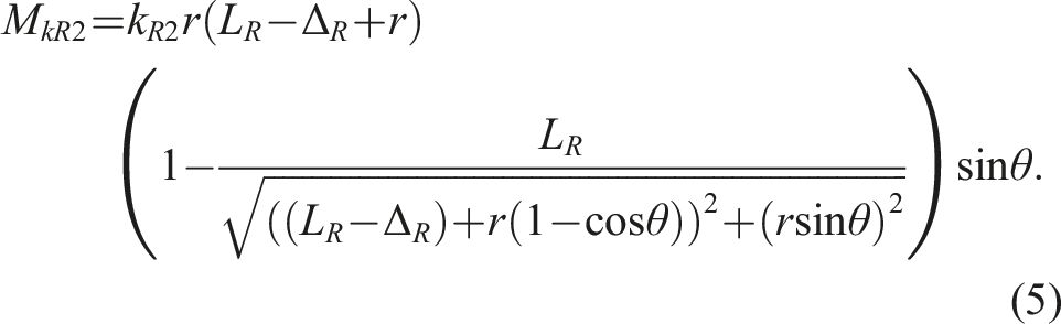
= 10 cm, and the stage is only allowed to rotate an amount θ, the system’s moment-rotation plot that would result from loading the stage with a moment, MkR2, according to Figure 5(c) would be the yellow line plotted in Figure 5(e) according to
If the same preloaded-spring scenario is then repeated but the torsional spring of Figure 5(a) is added back to the system as shown in Figure 5(d), the system’s moment-rotation plot that would result from loading the stage with a moment, M, would be the blue line plotted in Figure 5(e) according to

Note from Figure 5(e) that when the positive torsional stiffness of the orange torsional spring of Figure 5(d) is summed with the negative torsional stiffness of the preloaded yellow spring of the same figure, the torsional stiffnesses cancel and the system exhibits a region of near-zero stiffness where it is said to be statically balanced. If the preload is removed from the yellow spring of Figure 5(d) (i.e., Δ R is set to 0 cm), the resulting moment-rotation plot would be the green line plotted in Figure 5(e) according to equation (6). Note that the instantaneous torsional stiffness of the system of Figure 5(d) (i.e., the derivative of the system’s moment-rotation plot at θ = 0 rad) with the preload (i.e., Δ R = 10 cm) is 0 Ncm/rad but the instantaneous torsional stiffness of the same system without the preload (i.e., Δ R = 0 cm) is 100 Ncm/rad. Thus, this example demonstrates how dramatically the principle of stiffness cancelation can reduce the high stiffness state of a binary-stiffness rotational system to a low stiffness state by preloading a spring. Note that although the dimensions and stiffness values given in the example of Figure 5 do not correspond with the mechanism of Figure 3, the positive-stiffness orange torsional spring of Figure 5(d) is analogous to the positive-stiffness orange flexure bearings of Figure 3(e) and (f). Moreover, the preloaded negative-stiffness yellow spring of Figure 5(d) is analogous to the preloaded negative-stiffness yellow tuning springs of Figure 3(e) and (f). The red bistable switch of Figure 3(b) and (d) can be triggered to pop in and out for preloading and removing the preload from the tuning springs to reduce and increase the mechanism’s stiffness respectively similar to how the preload of Figure 5(b), Δ R , was toggled between 10 cm and 0 cm to generate the blue and green moment-rotation plots of Figure 5(e).
Experimental results
This section discusses details pertaining to the fabrication and assembly of the binary-stiffness compliant mechanisms of Figure 1. It also provides experimental data that characterizes the range over which their high and low stiffness states (i.e., stiff and compliant) can be changed along each of their two DOFs. Data is also provided pertaining to the repeatability of each mechanism’s switch.
The number and kind of unique parts that were additively fabricated for the mechanism of Figure 2 are shown in Figure 6(a). The number and kind of unique parts that were additively fabricated for the compliant mechanism of Figure 3 are shown in Figure 6(b). The orange, red, and yellow parts were fabricated out of eSUN PLA + using a Creality Ender-3 Pro 3D printer and the white parts were fabricated out of Prusament PLA using a Prusa i3 MK3S 3D printer. The parts were all assembled using bolts.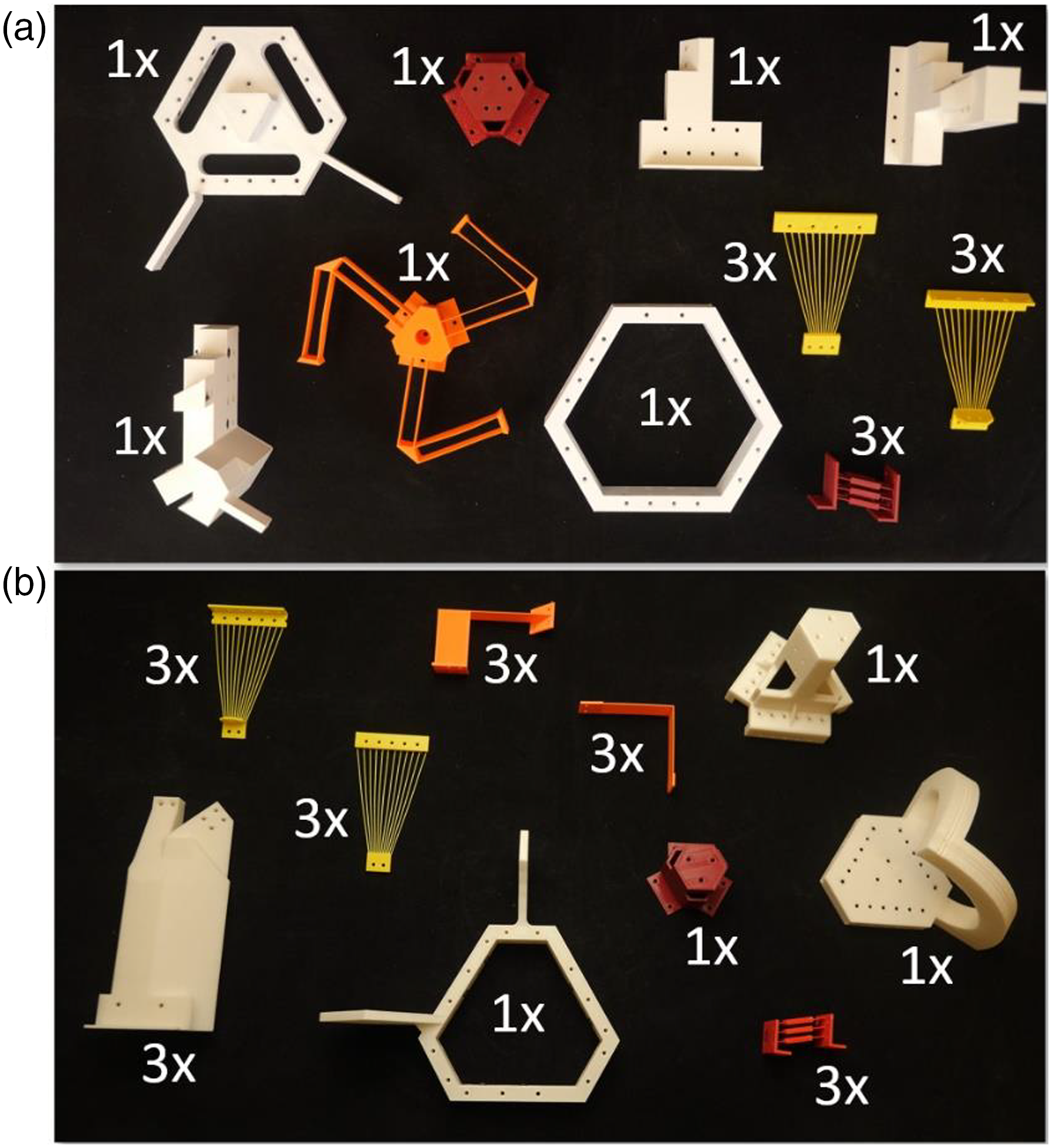
An Instron 5966 tensile testbench machine was used to experimentally measure the stiffness of the complaint mechanism of Figure 1(a) and (b) along its x-axis translational DOF in its stiff and compliant state as shown in Figure 7(a) and (b) respectively. With its switch oriented outward (i.e., configured in its stiff state), the mechanism was fixtured in the Instron’s clamps as shown in Figure 7(a) and was stretched and compressed over three cycles as shown by the force-displacement plot of Figure 7(c). The mechanism’s switch was then triggered inward as shown in Figure 7(b) and, in the resulting compliant state, the mechanism was again stretched and compressed over three cycles as shown by the force-displacement plot of Figure 7(d). The force-displacement plots of the third cycle measured from both the stiff and compliant state set to begin at the same location are plotted together in Figure 7(e) to enable a clear comparison of the stiffness change between both states. The stiffness (i.e., the slope of the force-displacement plot measured from the start of the third cycle at 0 mm – 0.5 mm) of the stiff and compliant state is 6.50 N/mm and 0.56 N/mm respectively. The mechanism’s switch was then popped back out and then triggered inward again to measure three more cycles of the second trial of the compliant state. The third cycle of both trials set to begin at the same location is provided in the force-displacement plot of Figure 7(f) to demonstrate the repeatability of the switch along the mechanism’s x-axis translational DOF. The binary-stiffness mechanism of Figure 2 being loaded by an Instron testing machine along its x-axis translational DOF in its (a) stiff and (b) compliant state. Force-displacement plots for three cycles of loading for the (c) stiff and (d) compliant state. (e) A force-displacement plot of the third cycle of both the stiff and compliant state plotted together. (f) A force-displacement plot of the third cycle of two trials of the mechanism triggered in its compliant state plotted together to characterize the repeatability of the mechanism’s switch.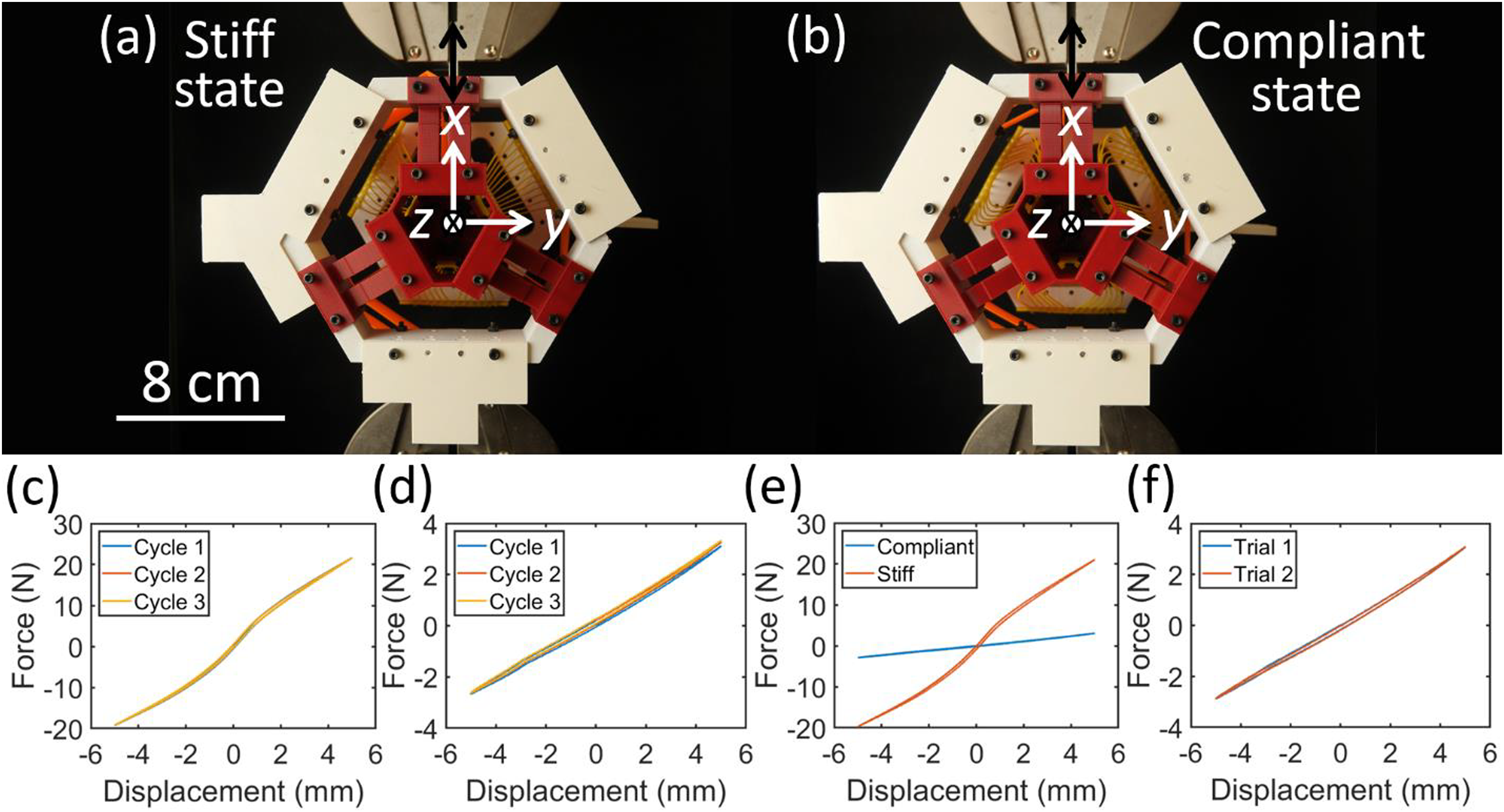
The Instron testing machine was then used to experimentally measure the stiffness of the complaint mechanism of Figure 1(a) and (b) along its y-axis translational DOF in its stiff and compliant state as shown in Figure 8(a) and (b) respectively. With its switch oriented outward (i.e., configured in its stiff state), the mechanism was fixtured in the Instron’s clamps as shown in Figure 8(a) and was stretched and compressed over three cycles as shown by the force-displacement plot of Figure 8(c). The mechanism’s switch was then triggered inward as shown in Figure 8(b) and, in the resulting compliant state, the mechanism was again stretched and compressed over three cycles as shown by the force-displacement plot of Figure 8(d). The force-displacement plots of the third cycle measured from both the stiff and compliant state set to begin at the same location are plotted together in Figure 8(e). The stiffness (i.e., the slope of the force-displacement plot measured from the start of the third cycle at 0 mm–0.5 mm) of the stiff and compliant state is 6.87 N/mm and 0.49 N/mm respectively. The mechanism’s switch was then popped back out and then triggered inward again to measure three more cycles of the second trial of the compliant state. The third cycle of both trials set to begin at the same location is provided in the force-displacement plot of Figure 8(f) to demonstrate the repeatability of the switch along the mechanism’s y-axis translational DOF. The binary-stiffness mechanism of Figure 2 being loaded by an instron testing machine along its y-axis translational DOF in its (a) stiff and (b) compliant state. Force-displacement plots for three cycles of loading for the (c) stiff and (d) compliant state. (e) A force-displacement plot of the third cycle of both the stiff and compliant state plotted together. (f) A force-displacement plot of the third cycle of two trials of the mechanism triggered in its compliant state plotted together to characterize the repeatability of the mechanism’s switch.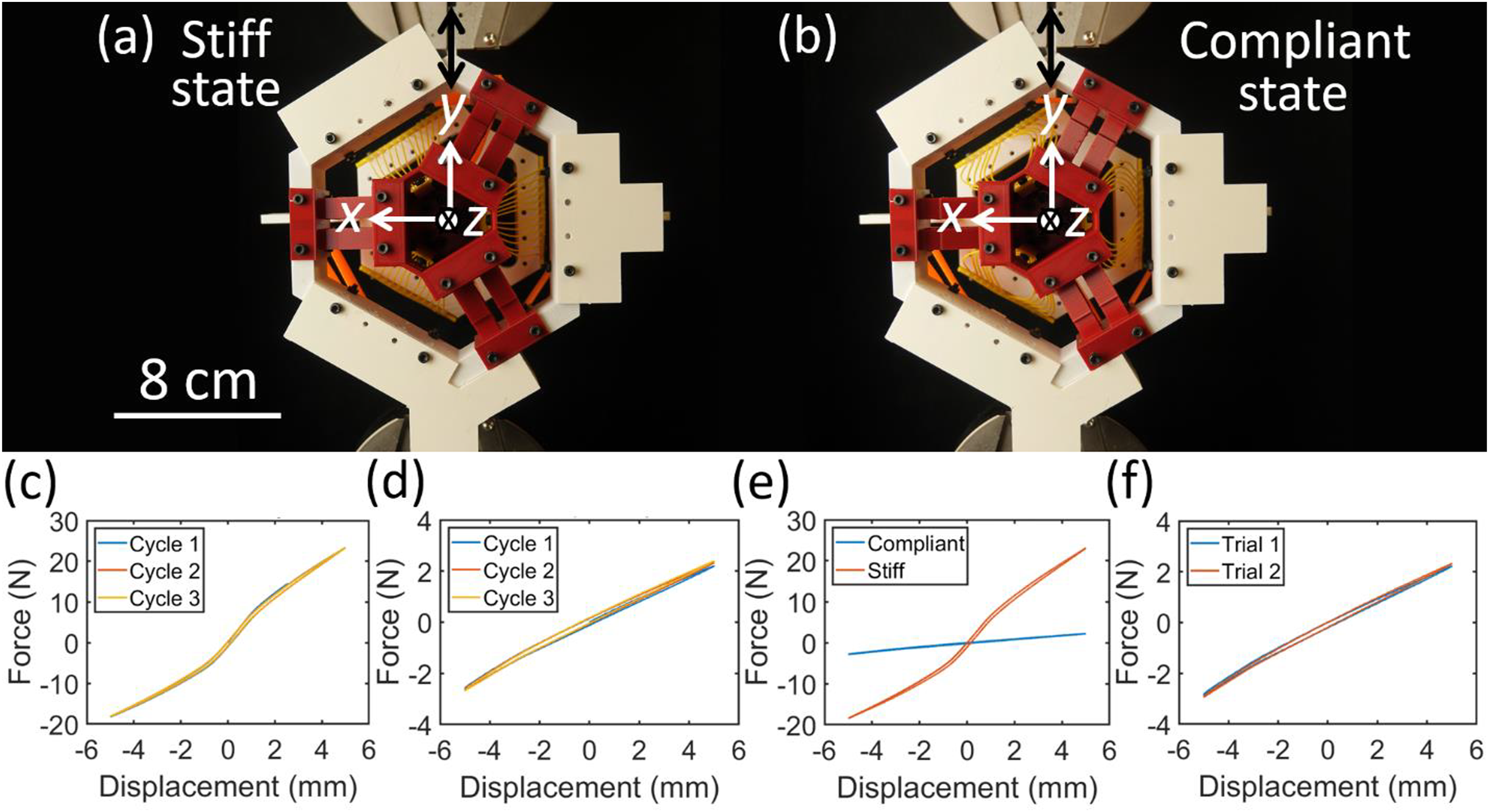
The Instron testing machine was then used to experimentally measure the stiffness of the complaint mechanism of Figure 1(c) and (d) about the x-axis rotational DOF in its stiff and compliant state as shown in Figure 9(a) and (b) respectively. The mechanism was fixtured in the Instron’s lower clamp as shown in Figure 9(a). To enable the Instron to impart a moment on the mechanism’s stage in both directions, a cable, highlighted green in Figure 9(a), was attached to the base of the stage’s circular track at one end, and was gripped by the Instron’s upper clamp at its other end. Another cable, highlighted purple in Figure 9(a), was attached to the top of the circular track at one end, and was attached to a 2 kg weight at its other end. Each cable rode within its own groove printed along the outside of the circular track as the Instron raised and lowered the hanging weight. The moment imparted on the stage was calculated by multiplying the force measured by the Instron (after it was zeroed out with the hanging weight included) with the radius of the circular track, R = 9.5 cm, labeled in Figure 9(a). The rotation of the stage was calculated by multiplying the displacement measured by the Instron with 180/(Rπ). With its switch oriented outward (i.e., configured in its stiff state), the mechanism was loaded counter clockwise and then clockwise over three cycles as shown by the moment-rotation plot of Figure 9(c). The mechanism’s switch was then triggered inward as shown in Figure 9(b) and, in the resulting compliant state, the mechanism was again loaded counter clockwise and then clockwise over three cycles as shown by the moment-rotation plot of Figure 9(d). The moment-rotation plots of the third cycle measured from both the stiff and compliant state set to begin at the same location are plotted together in Figure 9(e) to enable a clear comparison of the angular stiffness change between both states. The angular stiffness (i.e., the slope of the moment-rotation plot measured from the start of the third cycle at 0°–0.25°) of the stiff and compliant state is 0.294 Nm/deg and 0.041 Nm/deg respectively. The mechanism’s switch was then popped back out and then triggered inward again to measure three more cycles of the second trial of the compliant state. The third cycle of both trials set to begin at the same location is provided in the moment-rotation plot of Figure 9(f) to demonstrate the repeatability of the switch about the mechanism’s x-axis rotational DOF. The binary-stiffness mechanism of Figure 3 being loaded by an Instron testing machine about its x-axis rotational DOF in its (a) stiff and (b) compliant state. Moment-rotation plots for three cycles of loading for the (c) stiff and (d) compliant state. (e) A moment-rotation plot of the third cycle of both the stiff and compliant state plotted together. (f) A moment-rotation plot of the third cycle of two trials of the mechanism triggered in its compliant state plotted together to characterize the repeatability of the mechanism’s switch.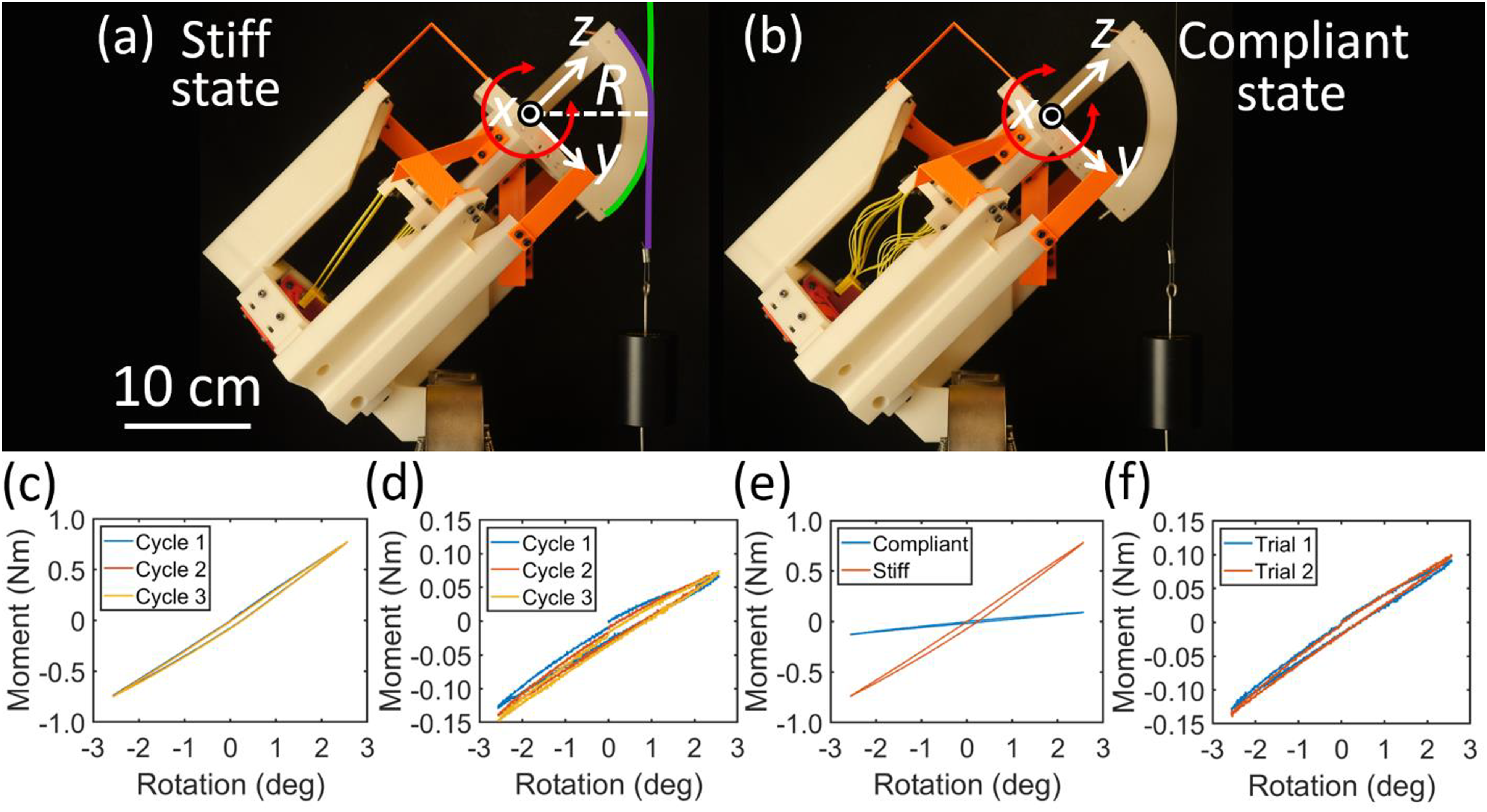
The Instron testing machine was then used to experimentally measure the stiffness of the complaint mechanism of Figure 1(c) and (d) about the y-axis rotational DOF in its stiff and compliant state as shown in Figure 10(a) and (b) respectively. The mechanism was fixtured in the Instron’s lower clamp as shown in Figure 10(a). It was loaded and measured using the same cable-weight approach discussed previously. With its switch oriented outward (i.e., configured in its stiff state), the mechanism was loaded counter clockwise and then clockwise over three cycles as shown by the moment-rotation plot of Figure 10(c). The mechanism’s switch was then triggered inward as shown in Figure 10(b) and, in the resulting compliant state, the mechanism was again loaded counter clockwise and then clockwise over three cycles as shown by the moment-rotation plot of Figure 10(d). The moment-rotation plots of the third cycle measured from both the stiff and compliant state set to begin at the same location are plotted together in Figure 10(e). The angular stiffness (i.e., the slope of the moment-rotation plot measured from the start of the third cycle at 0°–0.25°) of the stiff and compliant state is 0.286 Nm/deg and 0.031 Nm/deg respectively. The mechanism’s switch was then popped back out and then triggered inward again to measure three more cycles of the second trial of the compliant state. The third cycle of both trials set to begin at the same location is provided in the moment-rotation plot of Figure 10(f) to demonstrate the repeatability of the switch about the mechanism’s y-axis rotational DOF. The binary-stiffness mechanism of Figure 3 being loaded by an instron testing machine about its y-axis rotational DOF in its (a) stiff and (b) compliant state. Moment-rotation plots for three cycles of loading for the (c) stiff and (d) compliant state. (e) A moment-rotation plot of the third cycle of both the stiff and compliant state plotted together. (f) A moment-rotation plot of the third cycle of two trials of the mechanism triggered in its compliant state plotted together to characterize the repeatability of the mechanism’s switch.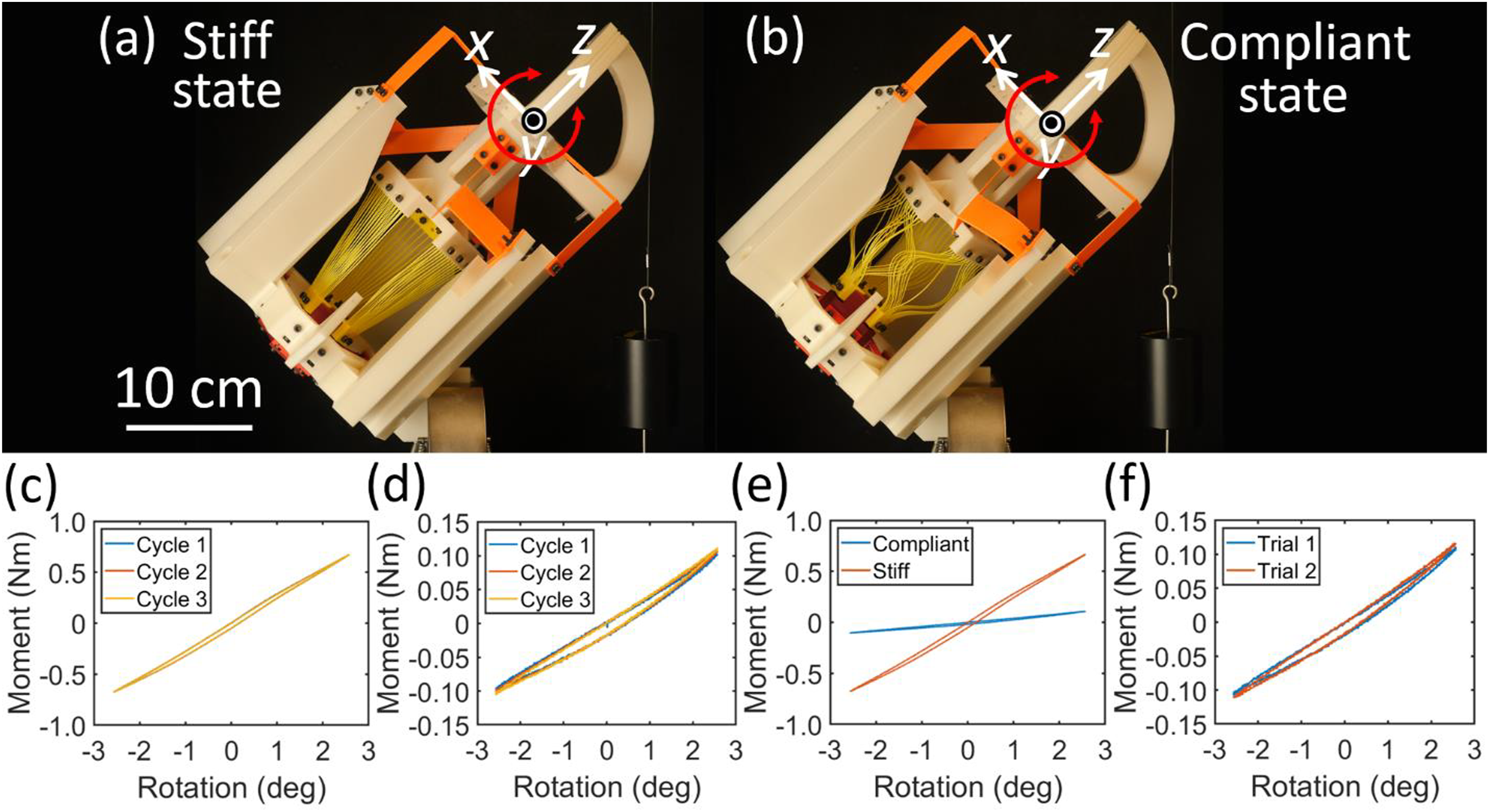
Conclusion
Example compliant mechanisms that achieve binary stiffness in two DOFs (i.e., x and y-axis translations and rotations) were introduced and experimentally demonstrated. These examples leverage principles of constraint manipulation and stiffness cancelation to achieve dramatic reductions in stiffness from their high to their low state of binary stiffness. The stiffness of the mechanism of Figures 7 and 8 was shown to decrease by 91.4% and 92.9% along its x- and y-axis translational DOFs respectively when it’s switch was triggered from its high to its low state. The stiffness values of the mechanism’s orange flexure bearings alone (Figure 2(a)) along its x- and y-axis, measured from 0 mm to 0.5 mm, was 0.71 N/mm and 0.63 N/mm respectively. Note that these values are greater than the measured stiffness of the full mechanism triggered in its compliant state (Figure 2(e) and (f)) along its x- and y-axis (i.e., 0.56 N/mm and 0.49 N/mm respectively). These results, thus, validate the presence of stiffness cancelation in the mechanism of Figures 7 and 8. The angular stiffness of the mechanism of Figures 9 and 10 was shown to decrease by 86.1% and 89.2% about its x- and y-axis rotational DOFs respectively when it’s switch was triggered from its high to its low state. The angular stiffness values of this mechanism’s orange flexure bearings alone (Figure 3(a)) about its x- and y-axis, measured from 0° to 0.25°, was 0.048 Nm/deg and 0.050 Nm/deg respectively. Note that these values are greater than the angular stiffness of the full mechanism triggered in its compliant state (Figure 3(e) and (f)) along its x- and y-axis (i.e., 0.041 Nm/deg and 0.031 Nm/deg respectively). Thus, these results also validate the presence of stiffness cancelation in the mechanism of Figures 9 and 10. Although hysteresis was observed in both mechanisms (predominantly in the rotational mechanism of Figures 9 and 10) due to the fact that the designs were 3D printed using polymer, both mechanisms achieved sufficiently repeatable binary-stiffness behavior. Additionally, although the wire flexures of both mechanisms’ tuning springs were observed to occasionally buckle differently each time their switches were triggered, the plots of Figures 7(f), 8(f), 9(f), and 10(f) all demonstrate that both designs are sufficiently repeatable for practical applications.
Supplemental Material
Supplemental Material
Footnotes
Acknowledgements
The authors acknowledge AFOSR program officer Byung “Les” Lee for his generous support.
Declaration of conflicting interests
The author(s) declared no potential conflicts of interest with respect to the research, authorship, and/or publication of this article.
Funding
The author(s) disclosed receipt of the following financial support for the research, authorship, and/or publication of this article: This work was supported by AFOSR under award number FA9550-22-1-0008.
Supplemental Material
Supplemental material for this article is available online.
References
Supplementary Material
Please find the following supplemental material available below.
For Open Access articles published under a Creative Commons License, all supplemental material carries the same license as the article it is associated with.
For non-Open Access articles published, all supplemental material carries a non-exclusive license, and permission requests for re-use of supplemental material or any part of supplemental material shall be sent directly to the copyright owner as specified in the copyright notice associated with the article.