
Abstract
Icing hazards often cause severe mobility concerns, safety risks, and even accidents in modern industries. Various ice mitigation strategies have been employed. Electro-thermal heating approach is a popular measure for ice protection, in which heat is generated electrically by internal components and then transferred to the outer surface for anti-icing and de-icing operation. Given the increasing usage of composites in aircraft structures, self-heating fibre reinforced polymer composite has been studied as an ice protection solution for the new generation aircraft. The present work focuses on improving electrical characteristics of carbon nanotube (CNT) based buckypaper (via surface functionalization) and the heating performance with an ice-phobic resin. The results indicated that surface functionalization of multi-wall carbon nanotubes (MWCNTs) was effective in obtaining MWCNT buckypaper (CNP) with improved electrical conductivity. The de-icing test confirmed the electro-thermal heating performance of the CNP based composite in a climate chamber at −20°C. The utilisation of surface modified MWCNTs in self-heating composites could be a promising strategy for maintaining lightweight and efficiency for electro-thermal systems to mitigate icing hazards.
Introduction
Fibre-reinforced polymer composites are gaining an increasing attention in modern industries like aerospace, automobile, and wind energy, because of their high mechanical strength and light weight. 1 However, in a cold region or environment, icing accretion on the composite surface often cause severe mobility concerns, safety risks, and even fatal accidents. Significant attention has been paid for developing smart de-icing systems to protect from the ice hazards in many industrial applications, including aircraft,2,3 telecommunications, 4 and power transmission. 5 Electro-thermal heating is one of the most popular approaches for the ice protection of polymer composites due to its capability of integration and controlling heat dissipation. 6 Typically an electro-thermal structure consists of a metal framework and an inorganic insulator which is normally complicated and heavy. Incorporating a traditional metal foil heater in a composite structure may create a weak layer, especially under inter-laminar shear force. 7 Thus, conductive nanomaterials into the composite structure has received increasing interest in the last decade,8–10 which could provide excellent self-heating capabilities for ice protection without sacrificing structure integration.
Carbon nanotube (CNT) is one of the most promising materials for electro-thermal heating elements of composite structures.8–11 Since the discovery of CNTs in 1991 by Iijima, 12 CNTs have been using in various applications because of their excellent mechanical and chemical properties, high electrical and thermal conductivity.13–16 Various applications of carbon nanotubes have been reported, from antiballistic vests 17 to electro-thermal elements.18–20 High electrical conductivity makes CNTs more attractive for electro-thermal application. Aouraghe et al.18,19 developed a flexible carbon nanotube film that could reach a steady-state temperature (>300°C) at low voltage, even after mechanical deformation and On/Off voltage switching cycles. Li et al. 21 produced a transparent, flexible thin heater based on graphene and CNT sheets using a dry spinning technique. The film revealed defrosting performance at 12 V and uniform thermal distribution even after bending for 10,000 cycles. Sun et al. 22 developed a CNT/thermoplastic polyurethane composite via a ball mixing and compression molding method. The obtained composite exhibited an electrical conductivity of 142.6 Sm−1 and a steady temperature of 65°C under 6 V applied voltage. Further attempts have been made to improve the intrinsic electrical conduction of CNTs-based structures through surface modification of CNTs using different acid treatment. The addition of functional groups (-OH/-COOH) on the surface of CNTs can significantly increase the electrical conductivity because of the increased mobility and charge carrier concentration, thus enhancing the metallic behaviour of the nanotubes.23–25 It was reported that the functional groups located at the contact area between the CNTs serve as conductance paths with lower electrical resistance. 26 Zhang et al. 27 showed an increase in electrical conductivity of MWCNT buckypaper from 1.3 × 10⁴ Sm−1 to 3.8 × 10⁴ Sm−1 after surface functionalization by acid treatment. Hong et al. 28 produced a transparent de-icing CNT film by spin-coating on glass substrate. Its effective de-icing capability under a freezing condition of −20°C was demonstrated with 80 V of applied voltage. Chu et al. 10 fabricated single-wall carbon nanotubes (SWCNTs) based composites for electro-thermal heating and de-icing applications. The SWCNTs were used to produce a buckypaper (SW-CNP), by filtration technique in glass fibre (GF) fabrics. The SW-CNP/GF/epoxy composites exhibited excellent heating performance in the temperature range of −22°C–15°C with a wind speed of 14 m/s, and the de-icing time 4–7 min. Rashid et al. 29 produced a CNT heater by a roll-to-roll slot-die coating process. The coating sample kept the heated area ice-free and further ice accretion was prevented with 40 V applied voltage. Yao et al. 30 developed a horizontally oriented CNTs film by chemical vapour deposition and embedded it in glass fibre fabrics to prepare composites for the de-icing purpose. During the de-icing test, the CNT/GF composites removed accreted ice within 15 s under a constant voltage of 16 V. Zhao et al. 31 developed a multi-layered ice protection coating by a combination of MWCNTs heating element with a super-hydrophobic layer. Compared to the traditional heating element, super-hydrophobic electric heating element showed up to 58% reduction in energy consumption. Recently, fibre reinforced polymer composites embedded with CNPs have been fabricated by pre-preg and resin impregnation methods, and excellent electro-thermal characteristics has been demonstrated. 32 Though the CNTs based self-heating element has demonstrated much improved heating performance, the overall electrical resistivity of the CNTs-based structure can be further lowered to increase the power density substantially.
The present work investigates the effect of surface functionalization on the microstructure of CNT based buckypaper and its effect on e-heating performances when impregnated with an ice-phobic resin. The acid treated buckypapers have been integrated into a composite structure by laminating the buckypaper with GF fabric followed by the impregnation in thermosetting resin (EL2 Epoxy laminating resin and Silikopon EF). EL2 Epoxy lamination resin is a commercial product used as a reference for comparison with the icephobic Silikopon EF. 33 Microstructures and defect states of MWCNTs before and after acid treatment were systematically investigated. The self-heating element, consisting of surface-modified MWCNTs and the corresponding composites using advanced ice-phobic resin, could be a promising electrical heating strategy to maintain lightness and efficiency in ice mitigation.
Experimental details
Raw materials
Multi-wall carbon nanotubes (95% purity) were purchased from Merck KGaA (Darmstadt, Germany). The nanotubes had an average outer diameter of 6–15 nm and length 2.5–20 μm. Nitric acid (70 wt%) was supplied by Fisher Chemical UK Ltd (Loughborough, UK). Triton X-100 (C14H22O(C2H4O) n ) was provided by Merck KGaA (Darmstadt, Germany). The glass fibre fabric (GF, thickness 0.185 mm), EL2 laminating resin and its hardener AT30 SLOW were purchased from Easy Composite (Stoke-on-Trent, UK). Silikopon EF resin was provided by Evonik Industries AG (Essen, Germany), which was considered as an icephobic resin.
Acid treatment
100 mg of pristine MWCNTs were dispersed in 50 mL nitric acid. The suspension was ultrasonicated in a bath for 2 h, followed by magnetically stirring for another 2 h. At the end of the acid treatment, the suspension was filtered, washed with distilled water until pH reached 7 and then dried at 60°C overnight. The obtained product was named as NA-CNT.
Preparation of carbon nanotube buckypaper
To obtain carbon nanotube buckypaper (CNP), which was a macroscopic aggregate of CNTs, a water-based dispersion of MWCNTs (100 mg, untreated or modified) and surfactant (0.1 wt% Triton X-100) was filtered through a PTFE membrane (Omnipore Membrane Filter PTFE, 1 μm pores). The CNT layer was peeled off from the membrane after drying at 35°C overnight. The CNP layer with desired dimension (55 mm × 55 mm) was obtained. The thickness of the buckypaper was measured in nine different positions by a digital feeler gauge.
Composite fabrication
The composite samples were fabricated by laminating the buckypaper between two GF fabric layers (60 mm × 60 mm square). The GF/CNP structure was soaked in 1.5 g resin (EL2 or Silikopon EF). Two copper electrodes (5 mm × 140 mm × 0.2 mm) were placed between the first GF layer and the CNP. This basic composite configuration was used to understand the effect of surface functionalization on the electro-thermal performance of the buckypapers. An optimised device configuration has to be considered to minimise the occurrence of thermal and mechanical stresses before being implemented on the industrial scale. A quick-drying silver paint from Agar Scientific was manually applied to the copper electrodes to attach with the CNPs to minimise the electrical resistance at the contact areas. The mould was made of two PTFE sheets covered with aluminium plates fixed with clamps. A schematic representation of the mould and the lay-up configuration is represented in Figure 1. The composites were heat-treated in an oven with different curing cycles. Silikopon EF resin was used as icephobic matrix. The soaked GF/CNP was placed in the mould and cured at 110°C for 16 h, with a heating ramp of 1˚C/min. While for EL2 laminating resin, it was mixed with AT30 SLOW hardener, with a weight ratio of 100:30, and stirred at 200 rpm for 30 min. The soaked GF/CNP was placed in the mould and cured in the oven at 65°C for 12 h, with a heating ramp of 1˚C/min. Schematic diagram of the layer-up configuration in the mould.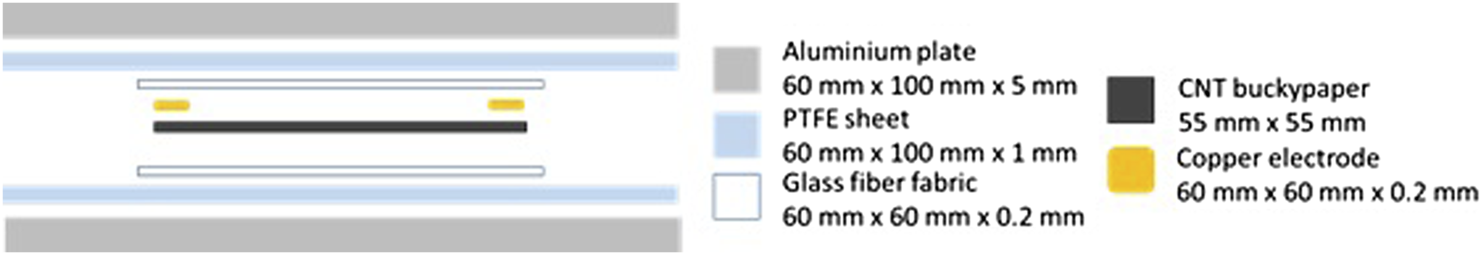
Characterisation
Microstructural characterisation
The microstructural characterisation was performed using Scanning electron microscopy (SEM), Transmission electron microscope (TEM), Raman spectroscopy, X-ray photoelectron spectroscopy (XPS) and confocal microscope. TEM analysis was carried out by a Jeol 2100F FEG-TEM with field emission electron gun (FEG) providing electron source at 200 kV, equipped with a GATAN Orius SC1000 camera for high angle angular dark field (HAADF). A high definition field emission scanning electron microscope (JSM - 7100F) was used for morphological characterisation of the buckypaper and the corresponding composite samples. Raman spectra were collected at room temperature using a triple monochromator (T-64,000, Jobin-Ivon/Horiba Group, Kyoto, Japan) equipped with a charge-coupled device (CCD) detector. The excitation source used a 532 nm Nd:YVO4 diode pumped solid-state laser (SOC JUNO, Showa Optronics Co Ltd, Tokyo, Japan) operating with a nominal power of 200 mW. The lateral resolution of the Raman microprobe was in the order of 1 μm. XPS analysis was performed by a photoelectron spectrometer JPS-9010 MC (JEOL Ltd, Tokyo, Japan) with an X-ray source of monochromatic MgKα (output 10 kV, 10 mA). The testing chamber was controlled under a vacuum level of 2 × 10⁻⁷ Pa. To neutralize the surface charge during data acquisition, a low-energy electron flood gun was used to deliver the electrons to the sample surface. A 3D laser scanning confocal microscope (Keyence VK-X150K) was used to analyse the surface rugosity of the buckypaper.
Electrical resistance
Figure 2 shows an assembled CNP heating device for testing the electrical resistance of the buckypaper. The device was composed of two Polyether Ether Ketone (PEEK) films (70 mm × 70 mm × 100 μm) placed in between two aluminium sheets (60 mm × 60 mm × 2 mm), one CNP layer in contact with two T-shape copper electrodes. The CNP films were laminated between the two PEEK sheets. Clamps were used to fix the devices and to keep the buckypaper in contact with the electrodes. CNP heating device for electrical resistance and heating performance tests: (a) schematic diagram of the layer assembly; (b) an assembled CNP heating device. CNP: carbon nanotube buckypaper.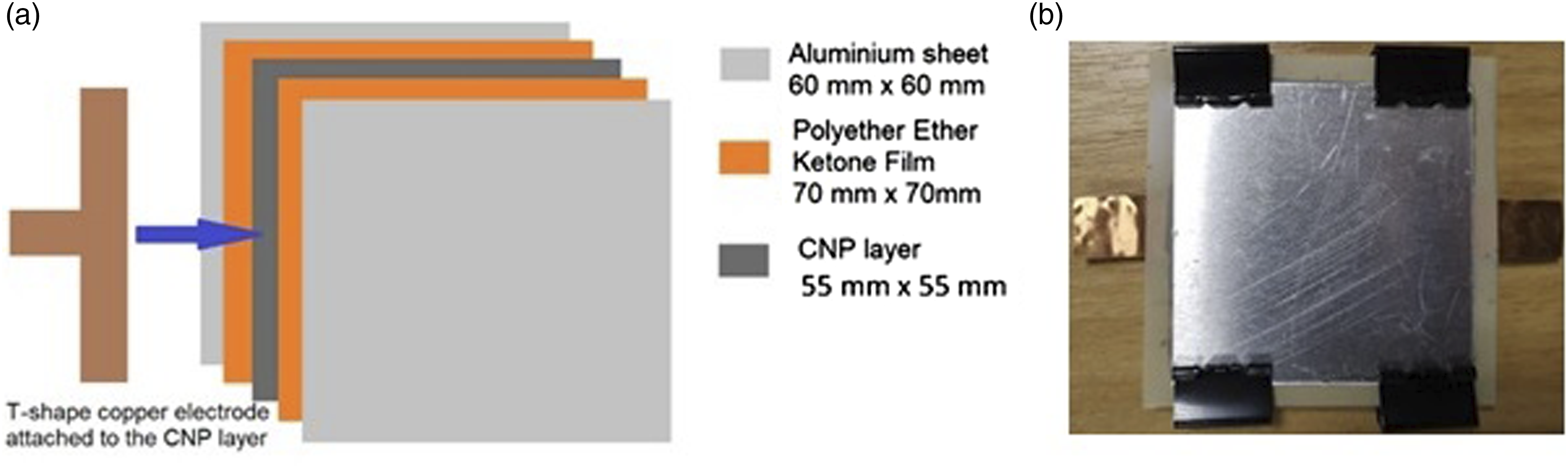
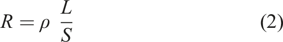
The prepared CNP and the respective composite samples were connected to a power supply (linear DC bench power supply CSI530S, by CircuitSpecialists) that provided a constant electrical potential difference (5 V) between the two electrodes. The electrical current was recorded and the resistivity of the sample was calculated by Ohm’s law

De-icing evaluation
The composite samples were placed in a cold chamber at −20°C and 100 mL of distilled water were nebulized and delivered into the chamber. A 2 mm thick rim ice layer was formed on the top surface of the samples. Then an electrical potential of 5 V was applied until the ice fully disappeared from the surface. An IR thermo-camera (FLIR E4, operating in Multi-Spectral Dynamic Imaging mode) was used to measure the temperature of the sample surface every 15 s from the start of the heating.
Results and discussion
Buckypaper
To study the microstructures MWCNTs after acid treatment, Raman spectroscopy has been used and the data is presented in Figure 3 after normalization. Both samples showed similar responses from the Raman spectra. The main features in the spectra are: D band, D′ band and G band. The D band, at 1350 cm−1,34–41 is caused by disordered structure or discontinuity/defect in the carbon nanotube network. The presence of disorder in sp2-hybridized carbon systems results in resonance Raman spectra.
42
The G band at 1580 cm−1 43–49 is induced by the crystalline graphitic structure. The distributed impurities, or defects in the nanotube structure, can cause the G-peak to split into two peaks, G-peak (1580 cm−1) and D′-peak (1610 cm−1). The split is due to the interaction between the vibrational modes of the impurities and the carbon atoms of the nanotubes structure.
42
The intensity ratio between G and D peaks remains the same in MWCNT and NA-CNT, further indicating that the amounts of amorphous and crystalline carbon remain almost unchanged. The reason behind this unchanged amorphous and crystalline carbon after acid treatment was confirmed from the TEM studies as discussed in the next paragraph. Normalized Raman spectra for multi-wall carbon nanotube (blue line) and NA-CNT (green line).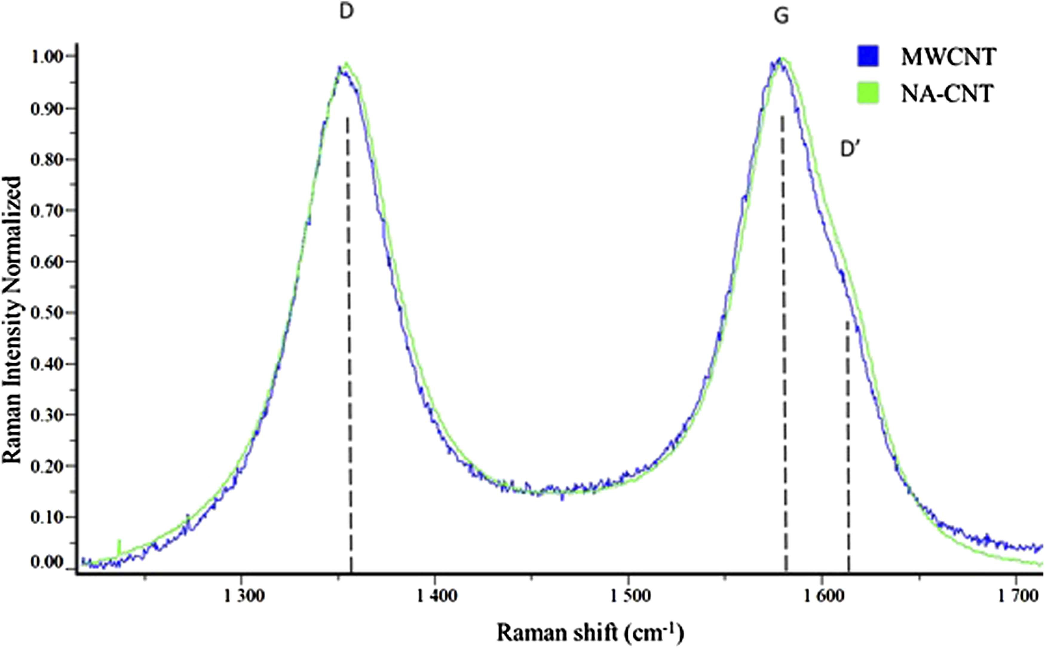
Figure 4 shows the TEM images of untreated and acid treated MWCNTs. The amorphous carbon content on the surface of NA-CNT (Figure 4(b)) is lower than the untreated one (Figure 4(a)). The oxidant treatment could have reduced the amorphous carbon.
50
An obvious structural change occurred in NA-CNT due to acid treatment, as observed in Figure 4(c) and (d). The graphene layers of CNT present different misalignments. The red circles highlight the area in which the acid may have attacked the nanotubes and the functional groups may attach onto the external wall of CNTs. Raman spectra indicates that the relative ratio between the amorphous/disordered and crystalline carbon did not change, i.e., the loss of amorphous carbon was compensated by the defect generation.
34
Transmission electron microscope images of: (a) untreated multi-wall carbon nanotubes; (b,c) defects (red circles) on multi-wall carbon nanotubes walls after nitric acid treatment; (d) a magnified image of one acid attacked position.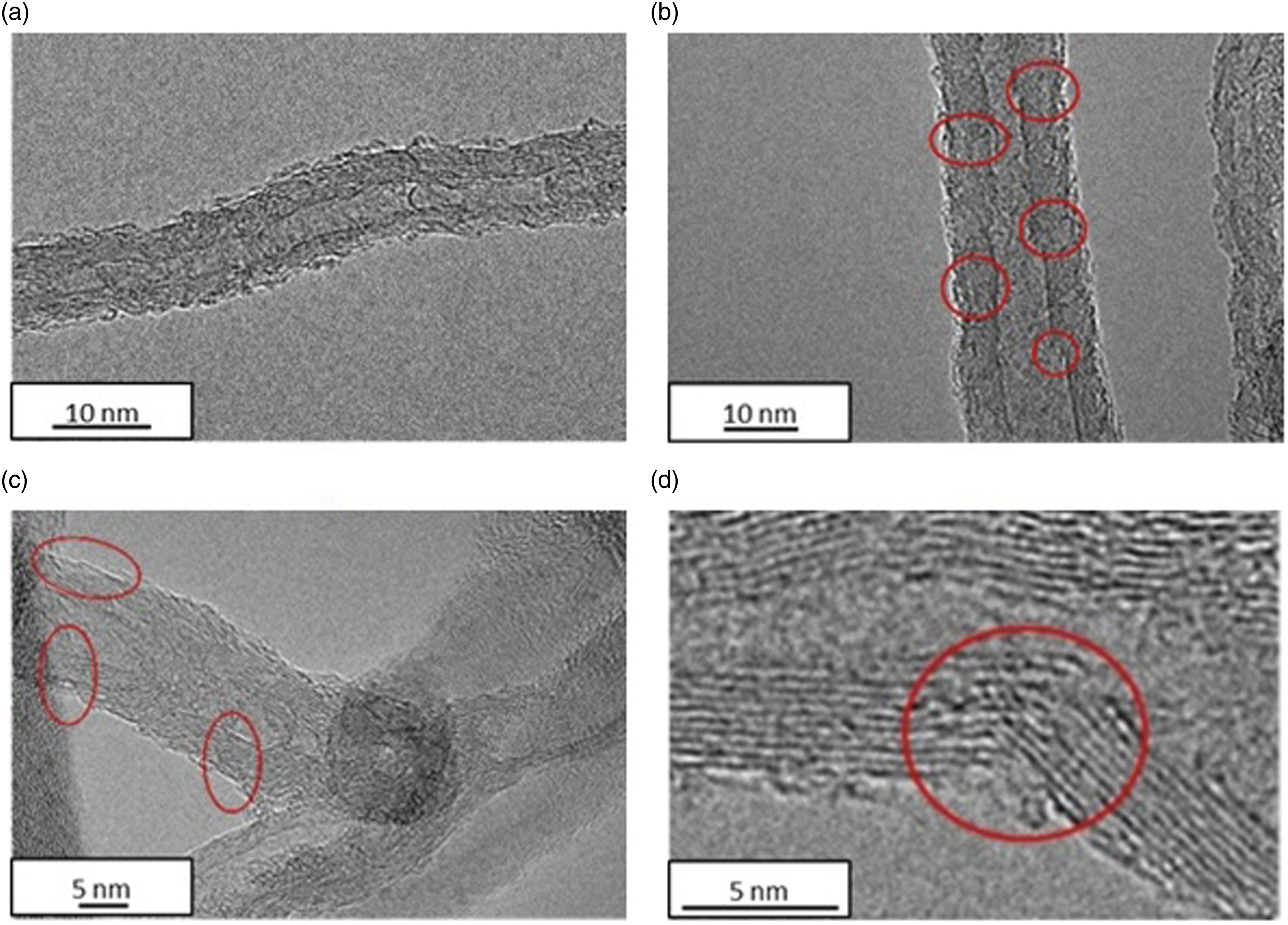
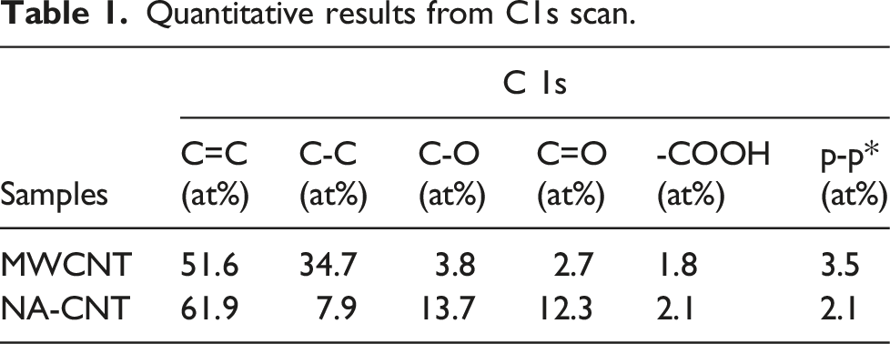
The changes in chemical states and bonding nature on the surface of carbon nanotubes have been analysed from the XPS study of C 1s core-level spectra. The deconvolution of the C 1s peak (Figure 5) helps to quantify the concentrations (at%) of oxygen containing groups (C-O, C=O and -COOH) in the samples, which is given in Table 1. NA-CNP corresponds to buckypaper made of nitric acid-treated CNTs; while MWCNP refers to buckypaper fabricated from untreated CNTs. The acid treatment creates defect sites on the graphitic network. The defects can be attributed to the result of carbon atoms being replaced by functional groups such as carboxylic acid (–COOH) and hydroxyl (–OH) on the CNT surface. The binding energy of the possible oxygen-containing groups is 286.0 eV for C-O, 287.1 eV for C=O and 288.8 eV for -COOH51–55 respectively. Any signal with eV > 289 could be classified as p-p* transition.51,56,57 Due to the acid treatment, the concentration of the functional groups on NA-CNT is higher than that on MWCNT confirming the successful addition of the functional groups on the surface of CNTs. C1s deconvolution for NA-CNT. Quantitative results from C1s scan.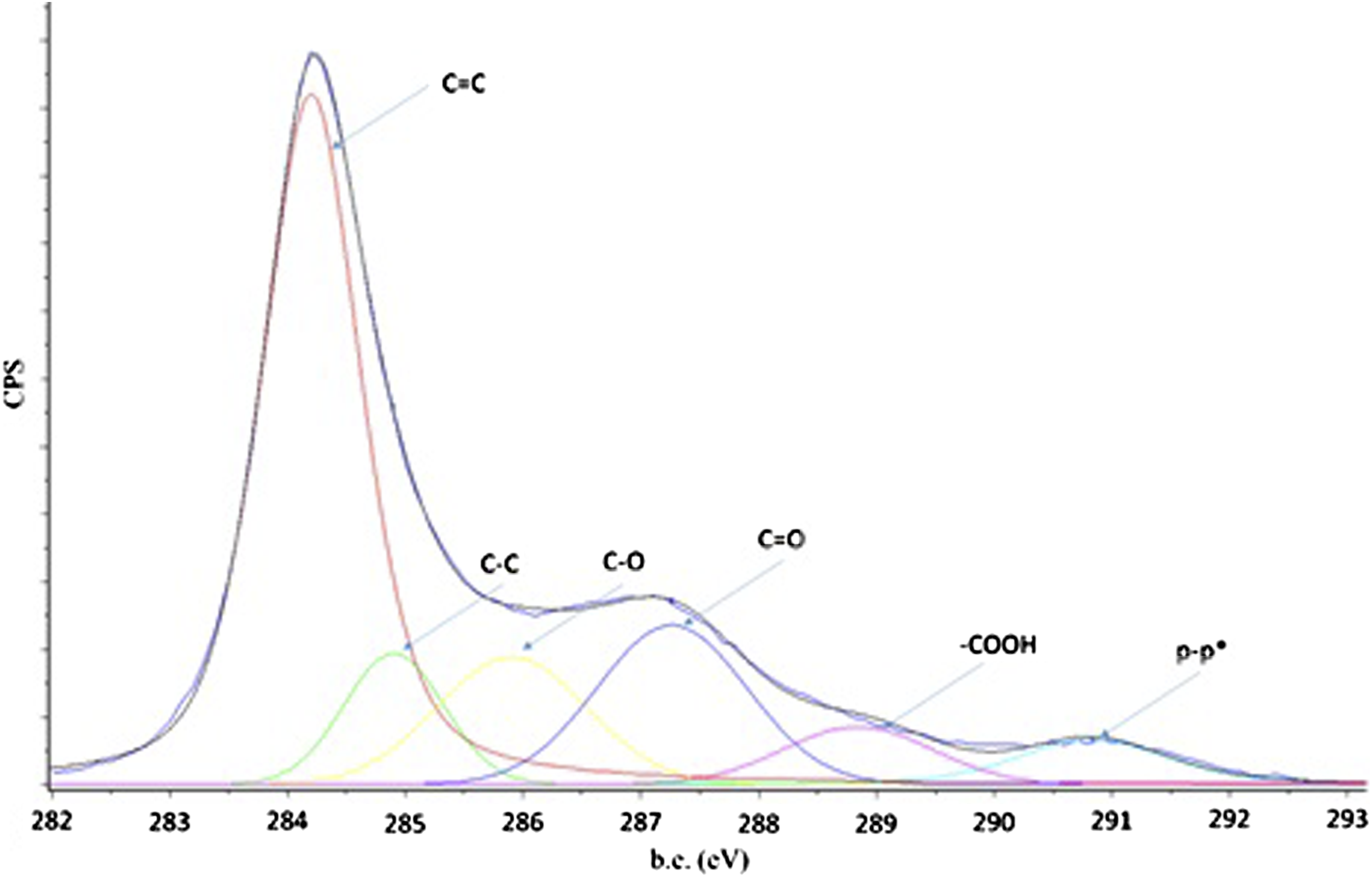
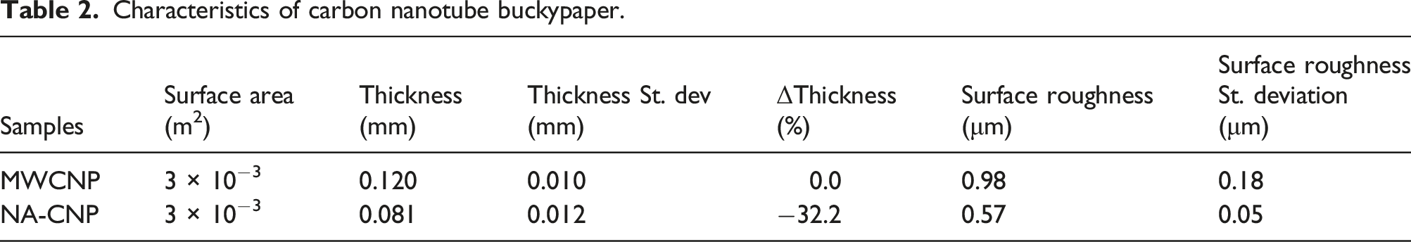
Characteristics of carbon nanotube buckypaper.
SEM images of the two types of buckypaper are shown in Figure 6. It is observed that nanotube aggregates are randomly distributed on the surface of MWCNP (Figure 6(a) and (b)), with length ranging from half to one micron. However, the amount of aggregates seems to be significantly reduced on the NA-CNP surface (Figure 6(c) and (d)), which could be attributed to the oxidation effect of MWCNTs.34,50,58 Nitric acid is a strong oxidizing agent, so that some amorphous carbon would be removed, making NA-CNP surface much flatter than MWCNP.
50
The reduction of amorphous carbon allows a more compact (around 32% less thickness) configuration in NA-CNP, without sacrificing the electrical conductivity, as noticed from the electrical resistances in Table 3. HNO3 oxidation freed the MWCNTs from the entanglements, causing a reduction of the CNTs aggregates. The lower surface roughness of NA-CNP than MWCNP, as observed from the laser microscope measurement, also confirms the reduced amount of nanotube aggregates in NA-CNP, which allows more compactness with reduced thickness. Scanning electron microscopy images of: (a) ×10000 MWCNP; (b) ×30000 MWCNP; (c) ×10000 NA-CNP; (d) ×30000 NA-CNP. Electrical properties of carbon nanotubes buckypaper.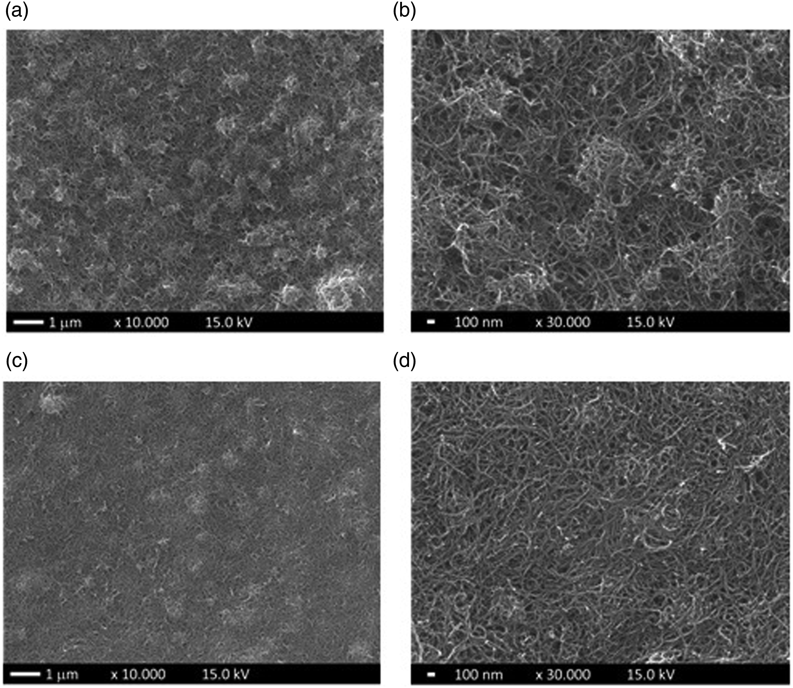
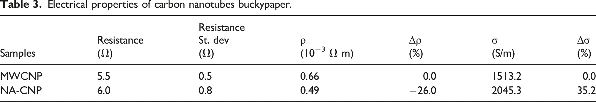
The electrical properties of buckypaper are listed in Table 3, including electrical resistance and the standard deviation, electrical resistivity ρ, and electrical conductivity σ. Δρ and Δσ are the changes in electrical resistivity and electrical conductivity, respectively, compared with the reference MWCNP. A wide range of power densities of self-heating elements have been reported in the literature. The power density values of 4–12 kW/m2 for metallic self-heating elements 30 (e.g., Boeing 787 wings), and 1–33 kW/m2 for nanomaterial based self-heating elements 30 (e.g., carbon nanotubes and graphene) were reported. The power density values of MWCNP and NA-CNP based self-heating elements are in same range of 1.5–1.6 kW/m2.18,19,30 Metallic self-heating elements are the standard products currently in use. In terms of energy consumption, nanomaterial based self-heating elements develop more heat than the metallic one with the same applied voltage thus could develop higher power density values.
The acid treatment has effectively reduced the electrical resistivity of the CNP layer and consequently, 35% increment in electrical conductivity is achieved in NA-CNP. Although the untreated and nitric acid-treated samples show close electrical resistances, a much thinner and more compact structure is formed using the acid-treated nanotubes. As a consequence, a significantly reduced electrical resistivity is obtained. Thus, nitric acid-treated CNTs are more effective for the construction of thin-layer of electrically conducting nanostructure network.
Characterisation and performance of the composites
Characteristics of the fabricated composites.
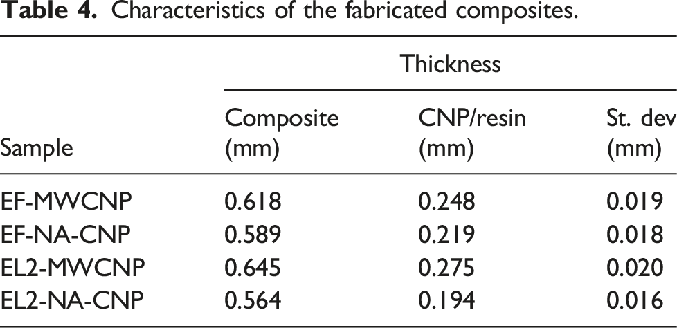
Figure 7 show SEM images of EF-MWCNP (Figure 7(a)), EF-NA-CNP (Figure 7(b)), EL2-MWCNP (Figure 7(c)) and EL2-NA-CNP (Figure 7(d)). From the SEM images, random distribution of the nanotubes impregnated with the thermosetting resin is observed. The buckypaper has been produced by filtration of nanotube dispersion (functionalised or untreated) and then impregnated with the resin. Both processes do not prompt any particular orientation or regular distribution of the carbon nanotubes. It is hard to notice clear differences in the distribution of the nanotubes. Scanning electron microscopy images (×60000) of samples cross-sections: (a) EF-MWCNP; (b) EF-NA-CNP; (c) EL2-MWCNP; (d) EL2-NA-CNP.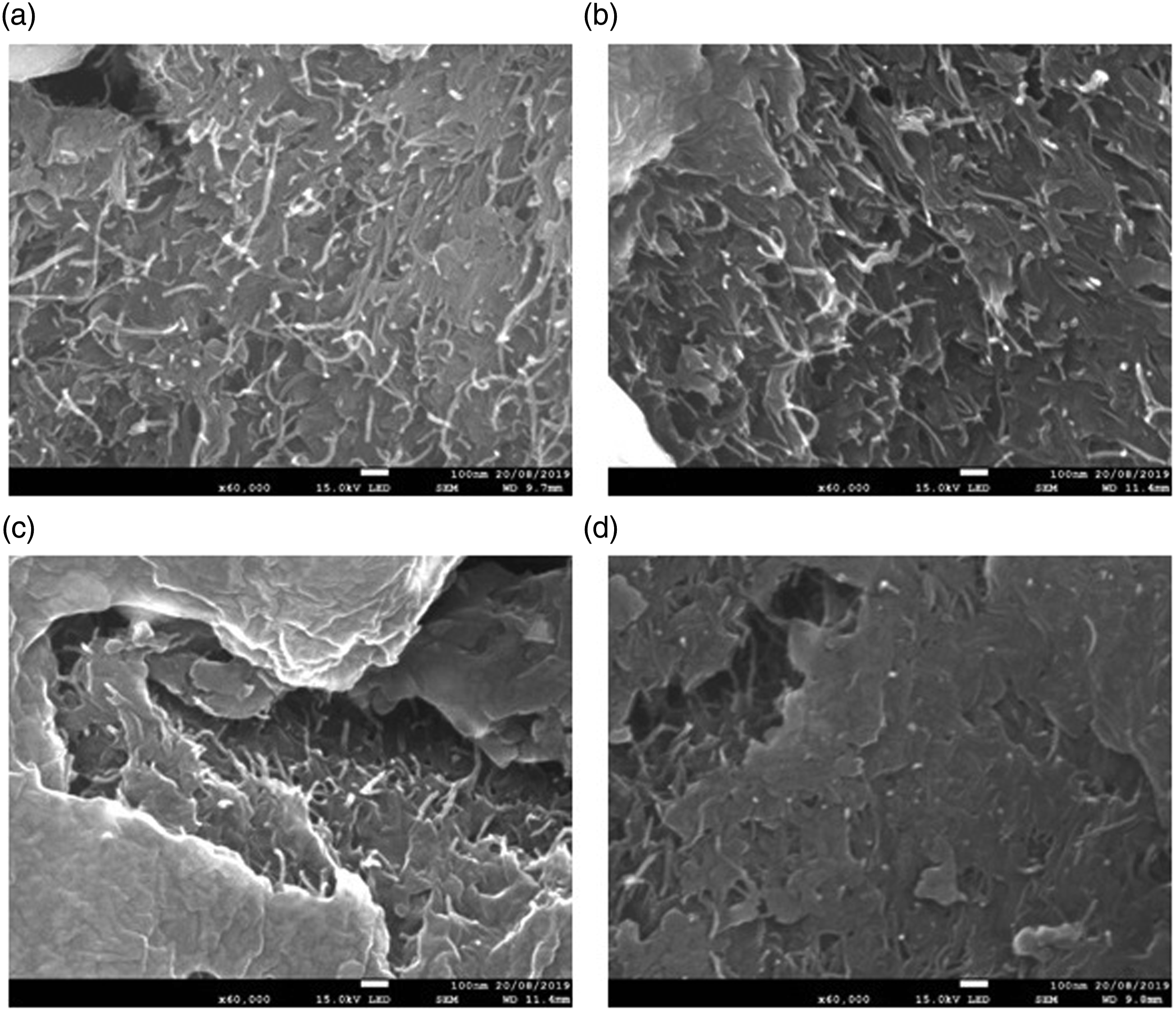
Electrical properties of the fabricated composites.
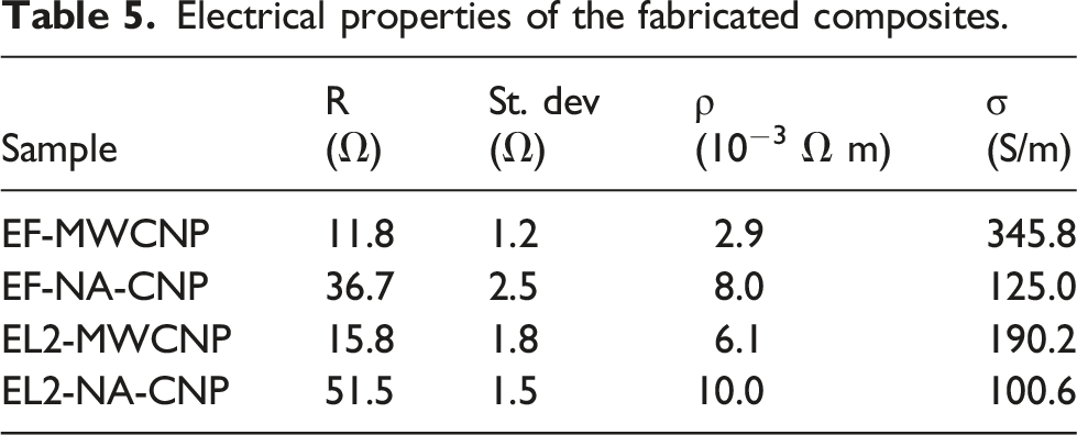
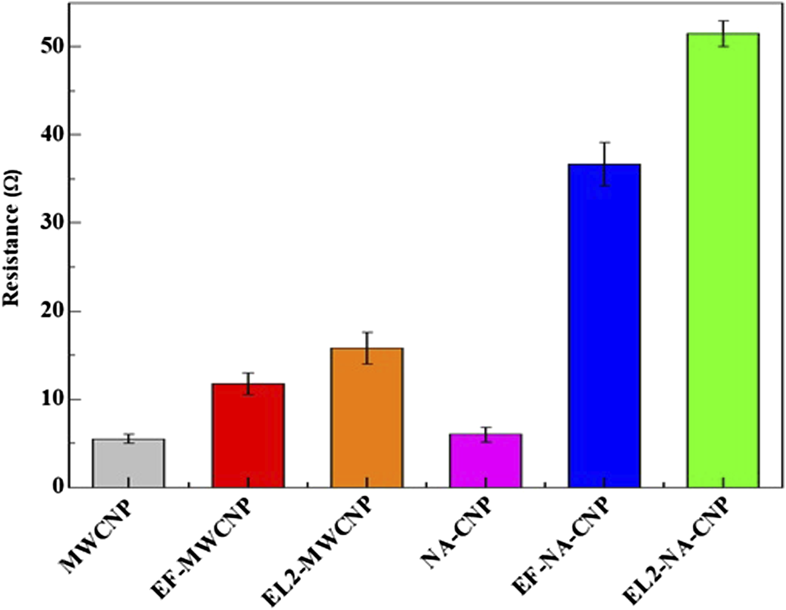
Comparison of electrical resistance between buckypapers and the composite samples with different resins.
Figure 9 shows the photos of de-icing tests and the corresponding IR thermal images during the ice melting. The composites were covered by rime ice at −20°C and a 5 V electrical potential was applied to provide the heating. This test condition was used to simulate an electro-thermal ice protection system under de-icing configuration. Optical images (first row) and the corresponding IR thermal imaging (second row) of the de-icing test for an EF-MWCNP sample: (a, d) at the beginning of the heating; (b, e) during the ice melting; (c, f) at the end of the ice melting.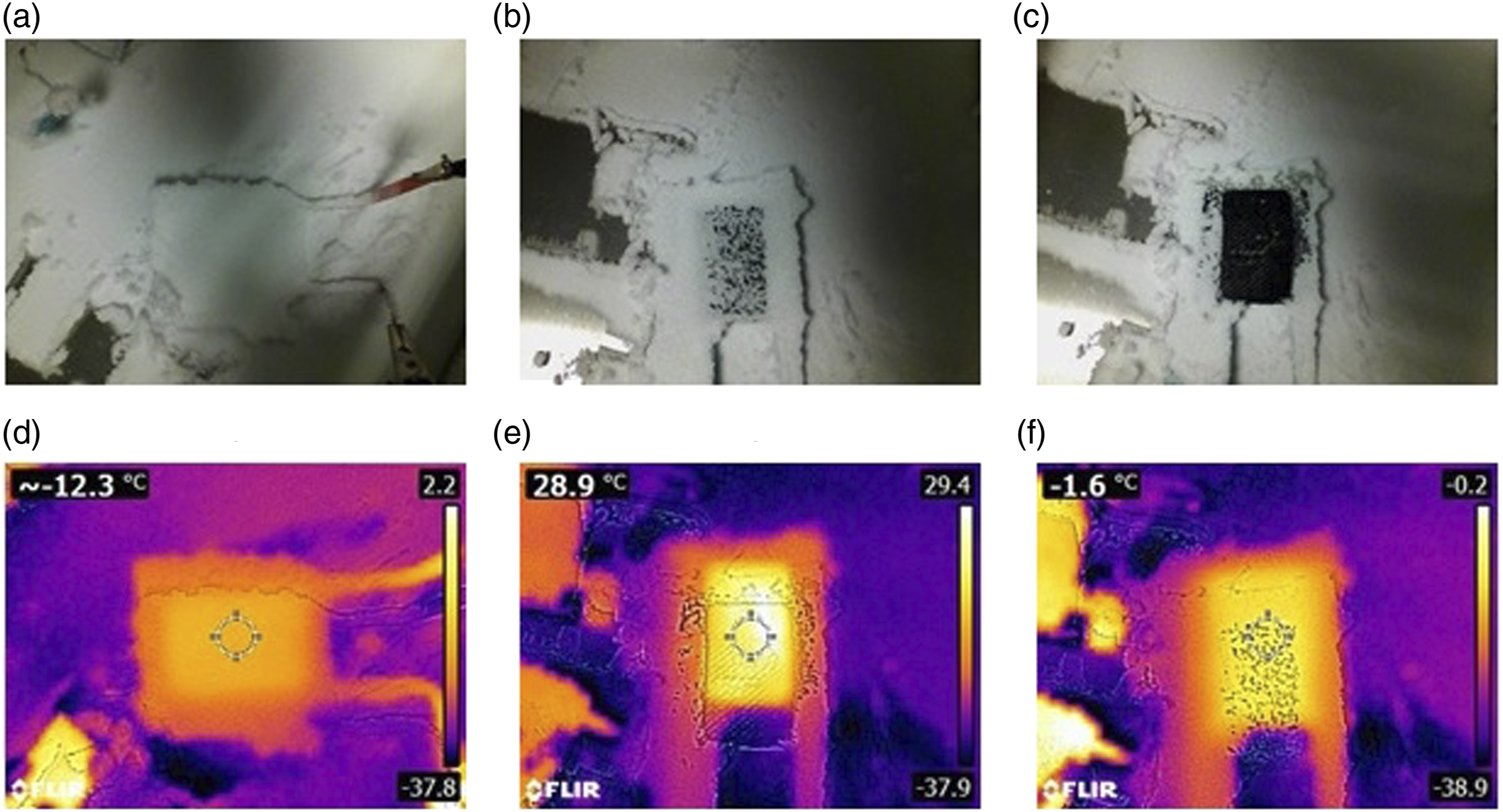
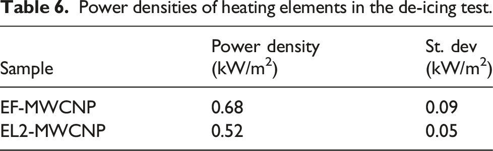
Figure 10 shows an increase in surface temperature of two samples (EF-MWCNP and EL2-MWCNP) during the de-icing test. The ice melting time is defined as the moment in which the temperature rises above 0°C. The ice melting time is characterised by a plateau of temperature values, i.e., from 50 s to 315 s, which is visible in Figure 10. During the ice melting, the measured temperature was slightly below 0°C (around −1°C ∼ −2°C). The IR camera measured the temperature at the centre of the sample during the ice melting (as shown in Figure 9(e)), where an ice/water mixed phase was observed. The ice melting started when melting spots appeared on the sample surface, as shown in Figure 9(b) and the procedure continued until all the ice disappeared from the sample surface, as shown in Figure 9(c). As the EF-MWCNP have an average electrical resistance lower than EL2-MWCNP, the ice melting of EF-MWCNP samples (⁓ 200 s) is faster than that of EL2-MWCNP (⁓ 315 s), which is highlighted by the shorter plateau in Figure 10 (from 50 s to 200 s). NA-CNP based composites have not been tested due to higher electrical resistance. A high electrical resistance would cause longer ice melting time. Temperature versus heating time during the de-icing test of EF-MWCNP and EL2-MWCNP samples.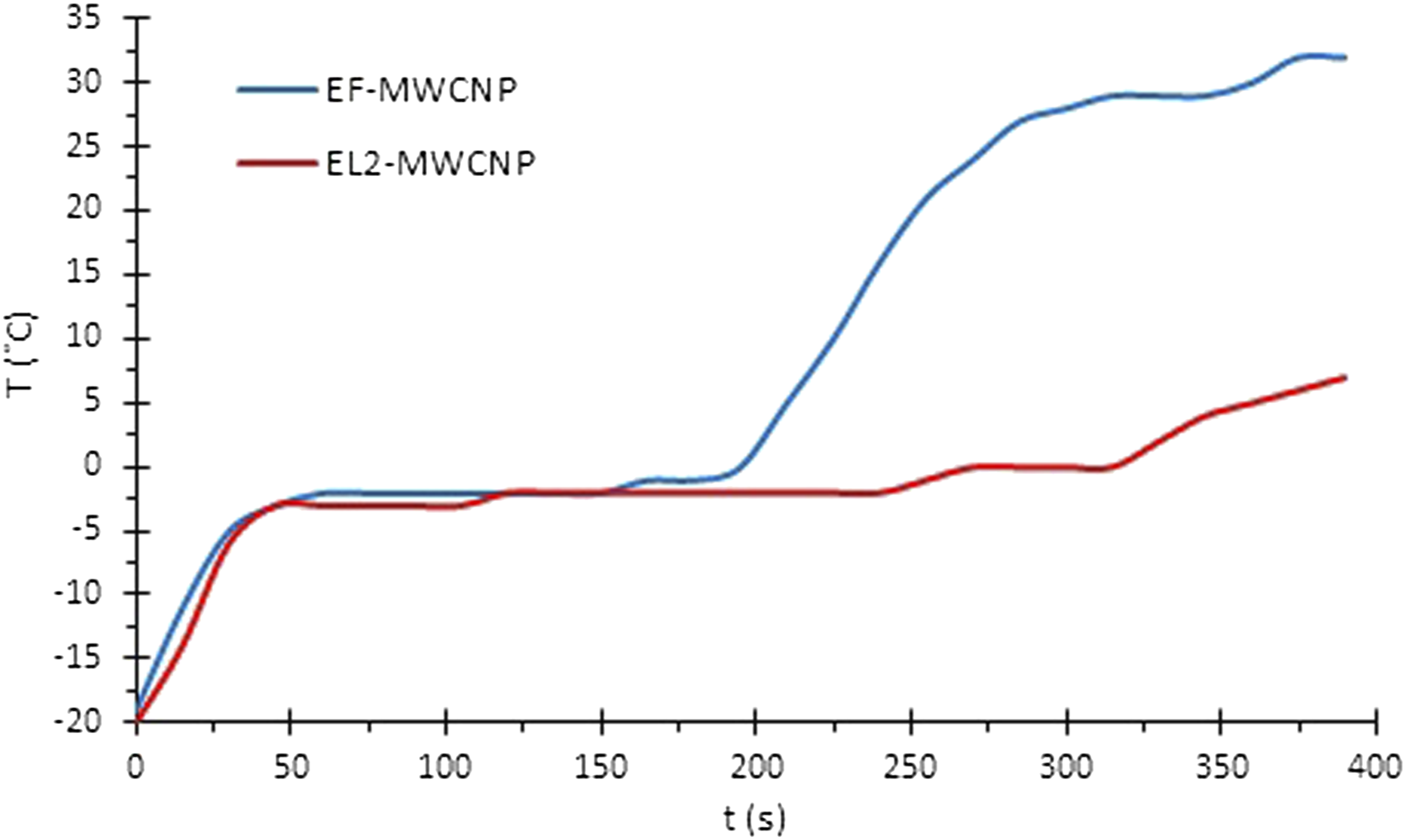
Power densities of heating elements in the de-icing test.
Conclusions
This work investigates the microstructural changes in CNT based buckypapers due to surface functionalization by acid treatment and the effect on heating performance when impregnated with an ice-phobic resin. The composites have been prepared by laminating the CNPs (both acid treated and untreated) with glass fibre fabric followed by the impregnation in thermosetting resin (EL2 Epoxy laminating resin and Silikopon EF resin).
The results indicated that surface functionalization of MWCNTs was effective in obtaining MWCNT buckypaper with improved electrical conductivity. The composites impregnated with Silikopon EF have lower electrical resistivity than the composites impregnated with EL2. The impregnation of EF resin reduced the formation of big CNTs bundles. The composites based on NA-CNPs exhibit a higher increase in electrical resistance with both resins. This was probably due to the more compact structure of the NA-CNP. It would be more difficult to impregnate the resin through the NA-CNT bundles. Diluting the thermosetting resin would allow it to penetrate into the CNP and reduce the increment in electrical resistance. The de-icing test confirmed the electro-thermal heating performance of the CNP based composite in a climate chamber at −20°C, indicating the potential to be integrated into composite structures for ice protection purposes.
Footnotes
Acknowledgements
Kyoto Institute of Technology is acknowledged for the instrument access in the placement. The placement was supported by Prof. Pezzotti Giuseppe, Prof. Marin Elia and all the colleagues of the laboratory.
Declaration of conflicting interests
The author(s) declared no potential conflicts of interest with respect to the research, authorship, and/or publication of this article.
Funding
The author(s) disclosed receipt of the following financial support for the research, authorship, and/or publication of this article: This work is funded by the INNOVATIVE doctoral program. The INNOVATIVE program is partially funded by the Marie Curie Initial Training Networks (ITN) action (project number 665468) and partially by the Institute for Aerospace Technology (IAT) at the University of Nottingham.