
Abstract
A novel preforming process was developed for non-crimp fabric (NCF) materials that generated in-plane tension through discontinuous blank boundary conditions. The method employed magnetic clamps and was designed to be both flexible and scalable, with clear routes to industrialisation. The capability of the process was explored in physical trials for a hemispherical and a cubic geometry. Characterisation of a biaxial veiled NCF showed the veil had a dominant effect on the bending mechanics. Subsequently a macroscale finite element model was developed to include an efficient bending idealisation and non-orthogonal in-plane material behaviour. Finally, global process optimisation of the preforming process was demonstrated. The optimisation approach used Gaussian process modelling with a periodic kernel to estimate the wrinkle size for untested clamping arrangements and then deployed Bayesian optimisation to find the optimal configuration. Results indicated that distributed magnetic clamping was effective and amenable to surrogate modelling.
Introduction
Dry fabric composites offer accelerated cycle times through efficient processing, out-of-autoclave manufacture, longer shelf life, and reduced dwell times. In comparison with prepregs, fabrics are also much easier to work with and manage on the shop floor. Non-crimp fabric (NCF) composites are now widely adopted across the aerospace and automotive sectors due to their reduced mass, as a result of keeping the fibres in-plane, when compared with woven materials. Manufacture and production processes, however, remain inflexible,1,2 resulting in added barriers in developing open, multifunctional systems toward the goals of industry 4.0. Even within highly engineered settings, such as the aerospace sector, composite manufacture is predominantly guided by a practical understanding of forming processes. Academic research into NCF forming is often outpaced by pressures on industry. Leading manufacturers are continually developing new protocols and manufacturing techniques, frequently with proprietary intellectual property rights. Research has also suffered from a lack of standardisation in what is a relatively new field. This adversely affects knowledge transfer and minimises the development of novel predictive modelling tools that can leverage diverse data sets. Herein, a unique adaptable manufacturing process is demonstrated, which allows tailored blank holder conditions using minimal hardware. The process employs magnetic clamps to provide scalable and flexible control of local mechanics through material tensioning. Bayesian optimisation is subsequently employed in combination with a predictive numerical model to effectively control the process.
Thus far, forming processes for NCFs have largely been borrowed from their crimped woven counterparts. These processes, including techniques such as diaphragm forming (DF), are beset with variability with little opportunity to accurately control boundary conditions (BCs) during pre-forming. They are also difficult to model, requiring an understanding of dynamic vacuum rates and fabric pinning, exacerbating variation in the quality of resultant parts.
3
Increasing demand for parts of additional geometrical complexity indicates a need for bespoke forming operations. External to this, material development is also ongoing, meaning additional lead time is required to fully characterise any given material. NCFs are highly engineered, and hence many variations of this material category exist. Within NCFs, biaxial fabrics are most common (Figure 1). They contain uniaxial fibre plies in two directions which are usually initially orthotropic. Additions such as toughening veils
4
are now common in the aerospace sector as well as a plethora of other modifiable parameters via the stitch.
5
[90v0v] Non-crimp fabric used for this study which employs a tricot-chain stitch, material orientation marked with red coordinate system. Note: ‘v’ in the ply notation denotes the interface where a veil is placed. (a) Front fibre side schematic (b) veil side schematic with (c) SEM of fibre side tow and stitch point and (d) SEM of tricot stitch showing the mixed strand veil and binder particulates.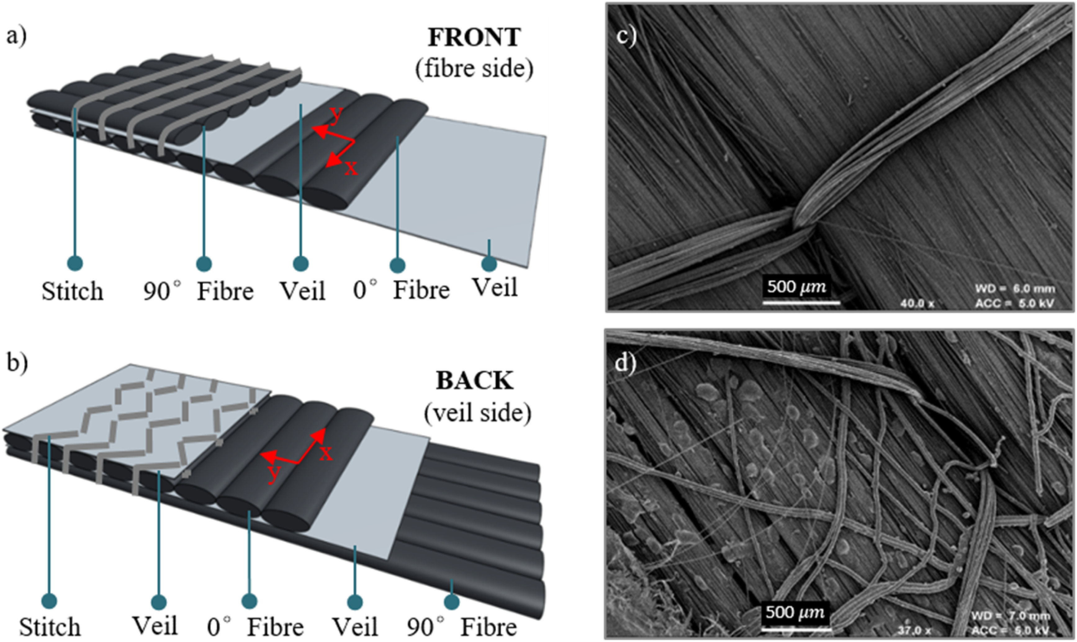
Asymmetric shear of some NCFs6–8 adds complexity to the material mechanics relation to geometry and has been shown to cause significant wrinkling.6,9 This asymmetry is the result of resistance to shear when one of the bias directions is aligned with a stitch direction. Asymmetric shear, however, can be reduced through choosing a fabric with balanced in-plane shear properties, such as biaxial NCFs which do not have a stitch path in the bias direction. A second method is through boundary control, which is a convenient and impactful process control parameter. Simple demonstrator geometries are typically used in forming studies to isolate desired effects. For example, a hemispherical tool, due to its implicit axisymmetry, facilitates evaluation of intraply shear. This is an active area of research, with the principle of differential shearing explored through spring-clamping,10,11 overstitching, 12 resin printing and pressure pads.13–16 These methods provide feasible routes to process control, but still carry barriers that prevent adoption in industry. These include high tensile forces and damage to the material, whilst requiring high accuracy in placement. Similarly, many methods require large mechanical assemblies and secondary processes, all of which increase production times. Continuous blank holders, which prevent out-of-plane bending can be advantageous in reducing unwanted out-of-plane wrinkles, however, continuous blank holders can also prevent beneficial out-of-plane deformation, particularly in relation to positive curvature. By damping this bending mechanism, material can remain inside the part and increase in-plane wrinkle severity. Discontinuous variable clamping, that allows more out-of-plane deformation in discretised locations, combines several of the benefits of the aforementioned techniques and few of their challenges. Specifically, the use of distributed magnetic clamping is explored in this paper. Distributed magnets allow for variable clamping forces at discrete locations, and can be applied to: the periphery or interior of the NCF sheet, against a supporting plate or against the tool itself. Magnetic consolidation has shown promise in reducing void content in vacuum assisted resin transfer moulding and demonstrates that permanent magnets could be easily utilised in production. 17 Large mechanical assemblies can be avoided and, thanks to the development of increasingly cheap suitable alloys, magnetic clamps are available to all levels of part production. The ease of application of magnetic clamps makes them appealing for studying boundary control, localised deformation, rate control, differential boundary forces, and multi-step protocols.
Simulation is a key tool towards understanding material behaviour. The commercial finite element analysis (FEA) package Abaqus is frequently used, making use of both membrane models10,12 and shell models. 18 Membrane models have the advantage of computational efficiency, but at the detriment of mechanical validity, particularly in forming protocols that include bending, whereas typical shell models overestimate the compressive stiffness. Novel developments to these models include the use of sub-modelling, 19 coupled elements, 20 laminated shell elements21,22 and more recently, coupled membrane and bending idealised shell models.3,23–25 Despite these advances, however, accurate computational models require substantial runtimes, meaning most models cannot be directly applied towards the global optimisation of industrial processes. Similar considerations apply to physical testing. For instance, there is a large reliance in research on digital image correlation (DIC). However, scaling this into industrial settings is often impractical. Stereo vision systems require line-of-sight access to the operation, whilst also being expensive, labour intensive and difficult to implement on a production line. Other methods, such as photogrammetry, are operationally similar, yet offer more flexibility.26,27 By focusing on flexible and scalable sensing techniques, it is possible to merge data sets from both research and industry, including from both physical experiments and simulations. In turn, increased volume and diversity of data fuel the deployment of Machine Learning (ML) techniques to optimise manufacture.
ML has already been shown to be powerful in the context of composite materials. Chen et al.10–12 recently demonstrated that genetic algorithms and artificial neural networks can successfully optimise component in-plane properties for a chosen geometry. Optimisation in this manner however, is often expensive to evaluate for new geometries. Hence others have explored alternative techniques which reduce computational requirements such as Bayesian optimisation and Gaussian process modelling, especially when coupled with convolutional neural networks (CNNs).16,23,25 Zimmerling et al. 16 highlight that significant computational savings can be made in feature and process level optimisation through optimised offline CNNs. These are, however, still limited by the size of training data sets, with features sufficiently separated. 23 Future approaches utilising feature and process level optimisation in a single package consequently seem likely. Bayesian optimisation,28–31 when coupled with Gaussian process modelling, 32 allows efficient optimisation that balances exploration and exploitation of the search space whilst outperforming stochastic gradient based methods in uncertainty quantification. 33 It appears that to improve the development of ML strategies, standardisation of some parameters is needed, in much the same way as was done for bias-extension characterisation. 34 This would allow much more inclusive training data sets that could be extrapolated to wider forming scenarios. An extensive review of ML for production processes is available in Ref. 35.
In this paper, an experimental method is proposed that can impose tailored BCs, which activate in-plane deformation modes, and allows for the subsequent evaluation of defects. The process is based on open-mould stamp forming, following similar deformation mechanics to that of DF. Neodymium magnets are used to clamp the material onto a forming bed, allowing interply slip whilst providing greater flexibility in their placement. The authors previously gave a summary of the experimental procedure in Ref. 26. That study showed that tailored boundary control in the bias directions prevented wrinkling. The same preliminary study highlighted that the distance between the magnetic clamps and the tool had measurable effects, in lieu of a changing magnetic force. Further research, undertaken in Ref. 36, revealed distributed clamping was also applicable to forming operations with multiple plies. In the following section, this experimental procedure is summarised for completeness and extended to quantitatively measure defects and to increase the geometrical complexity of the tool.
The magnetic clamping process was first demonstrated over a hemispherical tool, and second, over a more complex cubic geometry including features designed to induce large deformations. Separately, in-plane and out-of-plane properties of a veiled biaxial NCF (Figure 1) are characterised for the first time to facilitate creation of a parametric Abaqus model. Bayesian optimisation is then employed in conjunction with the FEA model to indicate the placement of magnetic clamps that minimise wrinkling.
Method
Distributed clamping process and experimental framework
All tests were conducted with a Tenax biaxial NCF (Teijen IMS65 E23 24K). This material consists of 0° and 90° unidirectional (UD) fibres with a polyamide copolymer (CoPA) tricot-pillar stitch. Below each UD ply, chopped strand toughening veils (ET205) are present. A powdered binding agent (EPIKOTE™ Resin 05311–15 gm−2) was also applied to the outer veil by the manufacturer. Figure 1 shows a schematic of the material composition and constituent plies [90v0v], with both front and back views. The front is distinguished as the ‘fibre side’, with stitches orthogonal to the 90° fibre, the back is defined as the ‘veil side’, faced with a veil and tricot stitches
Material sample preparation followed a rigorous process to reduce variability and induced pre-shear. This was achieved through masking the periphery of the cut lines with adhesive tape and using a rotary cutter to cut square samples with side length of 400 mm. Each specimen was sparingly sprayed with a suspension of hydrated magnesium silicate (Talc, Mg3Si4O10 [OH]2) in isopropanol (C3H8O) – in a ratio of 1:4 – to facilitate image analysis. The alcohol evaporated leaving a fine white powder, which did not affect structural behaviour, contrary to paint. This approach, coupled with the effects of the veil, reduced reflections from carbon fibres whilst also providing trackable features.
The axisymmetric hemispherical geometry implicitly amplified the influence of material anisotropy on forming mechanics and was used for one set of investigations. Using distributed magnetic clamping, a forming strategy was established and extended to a cubic geometry. Through these trials the impact of distributed clamping on the forming behaviour was assessed.
The distributed clamping test-rig developed for the hemisphere (radius = 60 mm) geometry is presented in Figure 2(a)–(c). As the hemispherical tool allowed evaluation of the magnetic clamping mechanism without the influence of local geometrical variability, developing the process with further complexity was desired. Typical aerospace parts usually have many planar sections, particularly in panels, spars and wings, and these parts have more features such as radii and tapers. A cubic geometry was therefore designed to replicate some of these complexities, see Figure 3. This part was a natural follow-up to the hemisphere, with comparable tool dimensions and only positive Gaussian curvature. Further, it was not axisymmetric but had four transverse planes of symmetry. (a) Distributed clamping process with hemispherical tooling in pre-deformed state (b) representation after full stroke. (c) Magnet positioner and coordinate system where four experimental test configurations are defined by The hemisphere and cubic geometry used in this study, which were machined from an aluminium and mild steel billet respectively. Radial insert schematics, with a 10 mm radius, were bonded to the forming bed and are shown taking a cross section through the Xx-axis (Figure 2).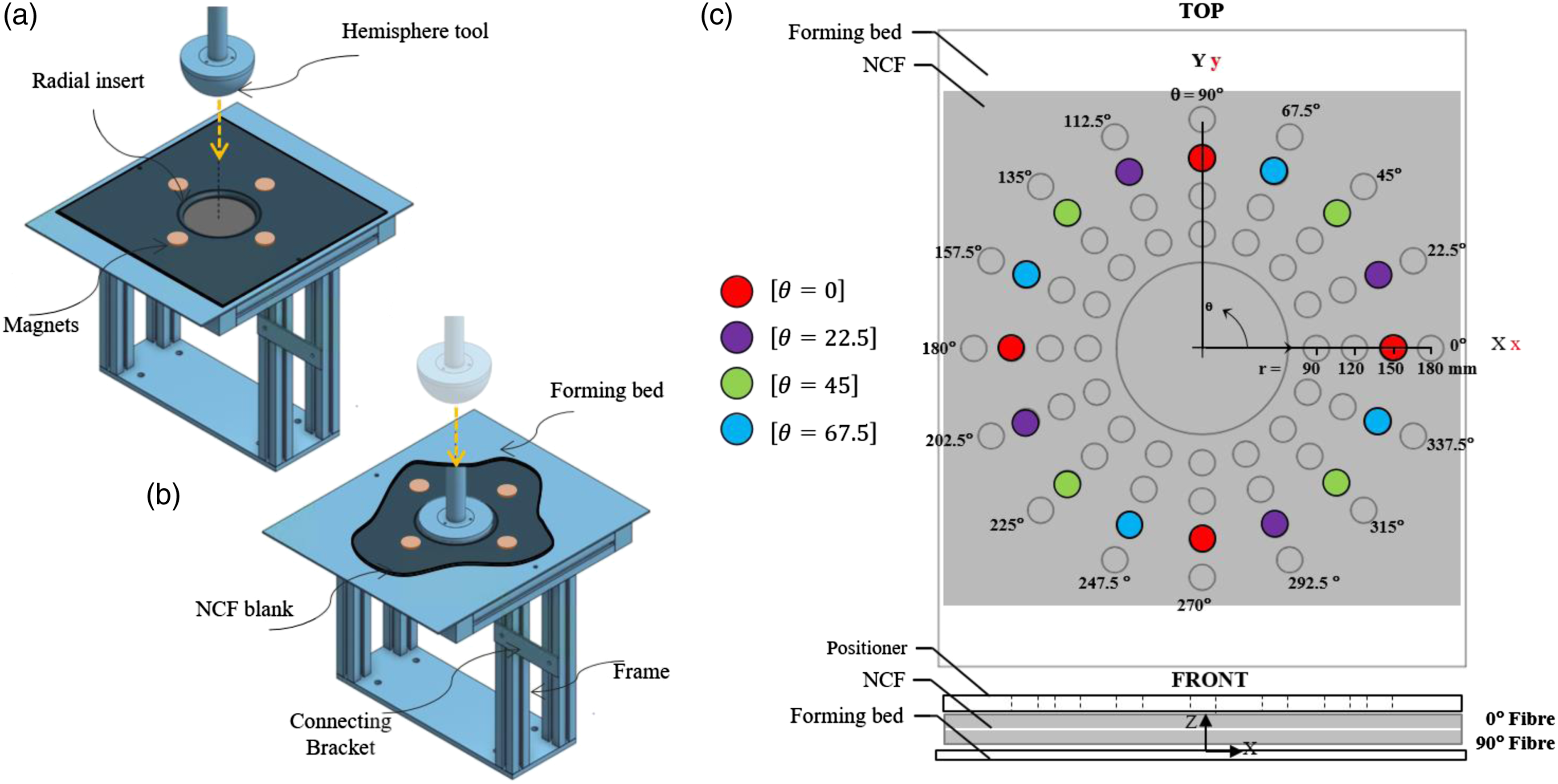
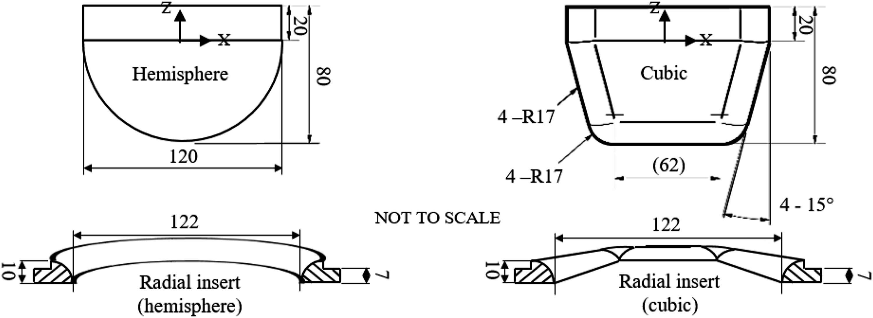
The rig was fixed to an Instron tensile test machine via mounting holes. A mild steel forming bed (400 × 500 × 3 mm) was attached to the supporting frame with a circular exclusion (radius = 61 mm). An insert with a 10 mm radius was then bonded to the internal exclusion. This part was vital for reducing stress concentrations that would lead to fibre or stitch damage and for efficiently transferring tension between the magnets and tool. The hemispherical and cubic tools were machined with a smooth surface finish from aluminium and steel billets respectively. The hemispherical and cubic tool included a 20 mm tangential extension from the equator to ensure no edge effect in forming, Figure 3. The NCF blank was placed on top (veil side up) of the forming bed and clamped in place using magnets at the specified test locations. NCFs tested were orientated with the material x-direction aligned with the positioner X-direction. This was achieved through use of a magnet positioner with pre-defined discrete occlusions, laser-cut from 3 mm MDF (medium density fibreboard), this was placed for positioning the magnets and removed before initiating the forming procedure. These corresponded to 16 angles at Symmetrical shear mechanisms present in the tricot-pillar stitched NCF used in this study. When 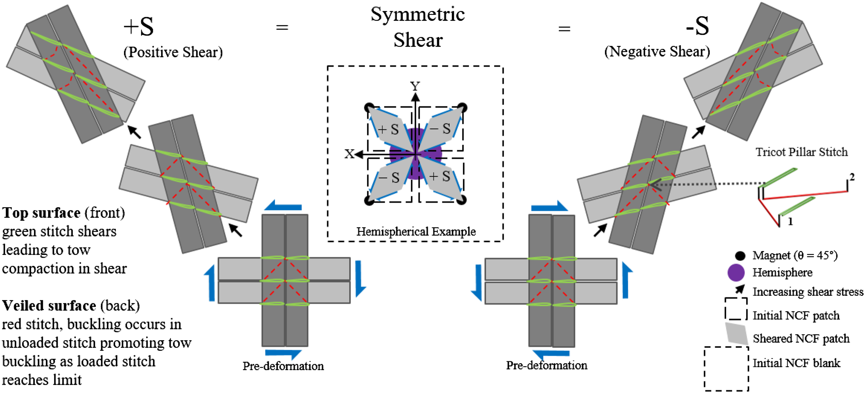
The test procedure was as follows: First the test rig was attached to an Instron 3369 tensile testing machine via the mounting plate and brackets. The mould tool was then fixed to a 1 kN load cell via a mounting bracket and pin. The NCF blank was placed centrally on the forming bed and orientated to the required position. Following this, the magnet positioner was employed to place the magnets at the test positions and removed once the magnets were all placed. The tool was first placed in contact with the NCF sheet and then lowered at a constant rate of 10 mm/min, moving a total of 61 mm along the negative Z direction, see Figure 3. As the experiment progresses the horizontal offset between tool and the radial insert decreases. During the final stages, this results in compaction of the fabric between tool and radial insert. This effectively clamps the material, promoting increased tensile forces that draw the material closer to the tool surface, allowing small wrinkles to re-orientate. On completion, both sides of the NCF were photographed using a Canon EOS 2000D SLR camera, ensuring full coverage of the specimens with 50–100 photos. Analysis through photogrammetry (Autodesk’s ReCap) produced a 3D reconstruction of the surfaces in the form of point clouds. These were subsequently scaled with the use of calibration markings on the radial insert, see Figure 5. Experimental photogrammetry and post-processing workflow. (Left to right) Raw images are converted into a 3D surface, cropped and aligned to a plane, scaled via calibration markings to the known distance (132 mm -white arrows), further processed to remove the radial insert and calibration markings. Finally, conversion to .ply file for computation of 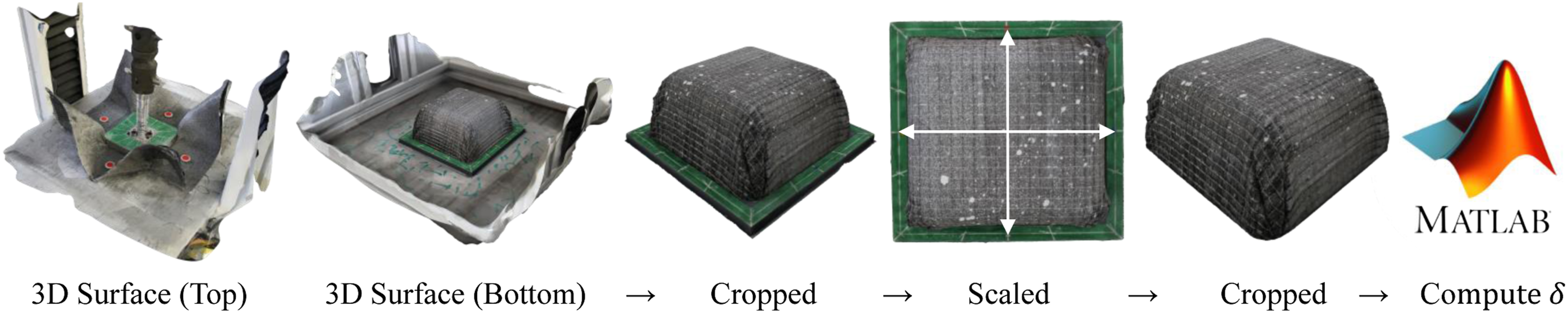
Extracting wrinkle morphology
Whilst photogrammetry is less accurate than 3D DIC, it is advantageous in other ways. Photogrammetry allows optimisation of image acquisition through its non-fixed set-up and therefore more data can be collected around particular features of concern. Readily available cameras permit reconstructed 3D models with high quality texture mapping, aiding analysis. We previously demonstrated the experimental capabilities of photogrammetry in Ref. 26, which has since been corroborated by Harrison and Gonzalez Camacho,
27
in a comparative study with white light scanning. A parallel study, outside the main scope of this work, showed photogrammetry achieved sub-mm precision over similar NCF preforms.
38
Photogrammetry’s fast deployment is more aligned with industrial capability and can be used at any scale. High quality strain information is less accessible to photogrammetry, particularly as this method only captures the final material morphology, but accurate measurement of wrinkle size can be achieved through numerical analysis of the point cloud. The process used follows Figure 5, where the top surface is shown to indicate the plausibility of image analysis to understand the magnet trajectories. The workflow is also amenable to automation and shows high quality scanned surfaces with texture mapping. As hemispheres can be described analytically, it is trivial to calculate the distance of the formed part from the origin of the hemisphere. This was measured at each coordinate in the point cloud,
The calculation of this metric was modified to deal with geometries that cannot be described analytically. Specifically, in those instances, a triangular mesh representing the tool surface,
Biaxial non-crimp fabric material characterisation
In-plane material characterisation
Bias extension tests with an aspect ratio of 2 were conducted according to the method described in Ref. 41 and 42 on an Instron 3369 tensile testing machine. The fibrous nature of the NCF did not allow successful DIC strain information to be gathered in this instance, hence axial strain information was based on output from the Instron, which included the displacement of the sample edge. Using the axial strain data from the Instron therefore produced an overestimate of the shear angles at high strains. This was quantified using ImageJ, (Fiji),
43
to extract the shear angle and deviation from the theoretical value, Figure 6. However, as this deviation is also attributed to edge effects, such as stitch breakdown and slip, the kinematic model was deemed suitable as these would break the pure shear assumption. While slip is not modelled, we can hypothesise that, in the physical forming trials, some amount of slip will occur between the shear angles of 30° and 60°. Whilst this study did not aim to develop a state-of-the-art material model, macroscale modelling results presented later highlight the efficacy of this simplification. The resulting normalised relationship between shear stress and shear angle was fitted via MATLAB’s fitting toolbox as a rational polynomial. To allow the development of simplified hyperelastic behaviour at high strain, a second exponential fit was added to the shear stress formulation. The shear stress, illustrated in Figure 6, therefore had the following formulation Left, theoretical kinematic (dark blue) and experimental measured (light blue diamonds) comparison of shear angle versus axial displacement. Percentage deviation between the measured and theoretical (orange dashed) and right, resulting in-plane shear stress, shear angle relationship, with equation (1) (dark blue) and equation (2) (red).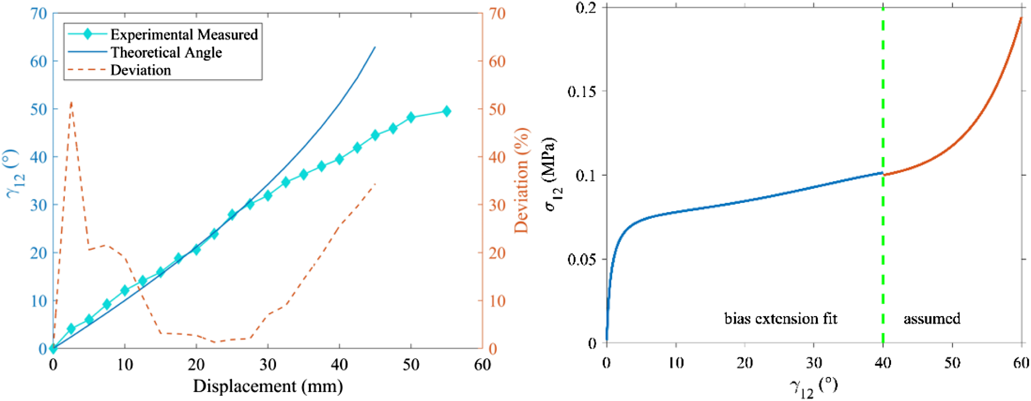
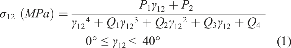

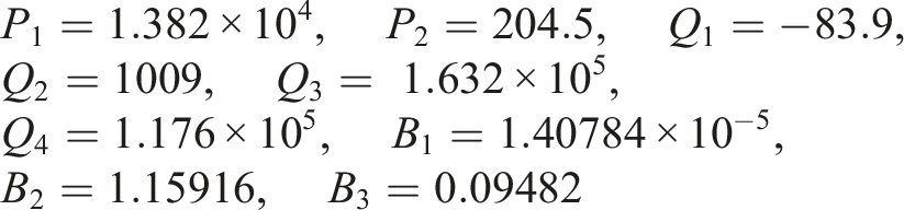
with coefficients
Out-of-plane material characterisation
Unlike continuous blank holder restricted processes,
14
the material was able to bend out-of-plane between clamps. Hence, both membrane and bending properties contribute to the deformation mechanics. To evaluate the bending response, Shirley cantilever tests18,20–22,44,45 were performed according to BS EN ISO 9073–7; 1998
44
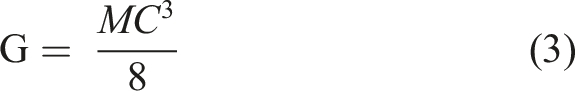
to calculate bending stiffness per unit width
The bending experiments showed that the veil and stitch architecture influenced the out-of-plane mechanics. This can be evaluated from Figure 7 orientation 2, whereby having the 0° fibres on the top surface gave a bending stiffness nearly half the magnitude to orientation 3. This is not only attributed to displacing the 0° fibres 0.5 mm above the fulcrum, but also to the addition of the veil and binder. When the veil sandwiched a 90° fibre layer on the compressive bending region [0v90v], it acted as a stiffener in preventing rotations of the tows. When the veil was removed from this location [v0v90], the 90° tows were free to rotate, significantly reducing the bending stiffness. Further, Figure 1(d) shows binder particulates appear to have partially cured and fused with the fibre sizing. This would increase the compressive stiffness on the mesoscale, allowing load to transfer between the 90° and 45° fibres when in compression (see Figure 7, orientations 4–5). Without the binder or veil, compressive resistance comes from the stitch. This may have important implications for macroscale homogenisation strategies that aim to capture the full effect of the anisotropy. Bending orientation schematics are shown on the left. Six samples were tested in each orientation and the bending stiffnesses shown on the right were calculated. The red bars indicate the standard deviation for the six measurements. * Wider samples (100 mm) for bias orientation.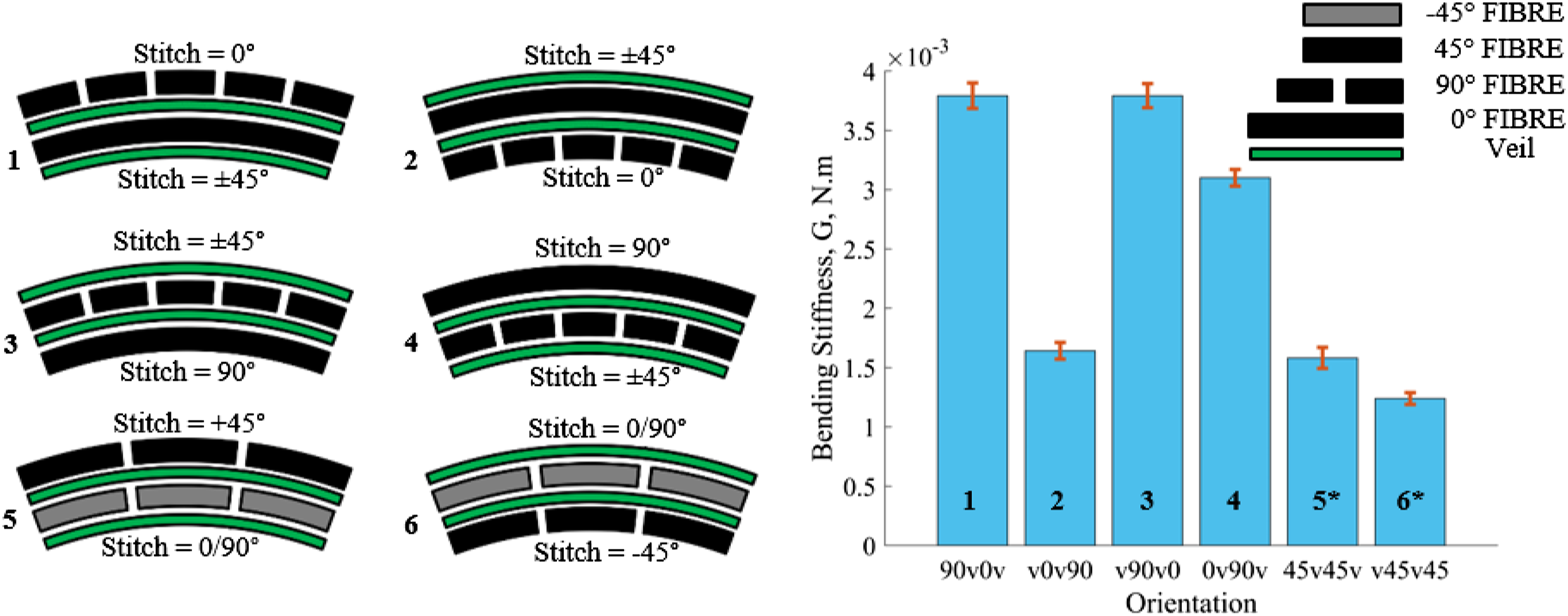
Finite element model
A dynamic explicit analysis was chosen in Abaqus for all FEA models. To model the NCF efficiently, we assume an elastic material with a zero Poisson’s ratio in the direction of the fibres and we ignore tow slip that can often emerge at large shear. These assumptions enable a simplified homogenisation of the material properties. By definition, membrane models cannot capture the bending behaviour. Thus, a coupled membrane and shell element approach was pursued in this study similar to Ref. 3. Using a shell model in solitude, would not allow the decoupling of the in-plane and out-of-plane behaviours. To achieve this in Abaqus, shell elements and membrane elements were defined, whilst sharing superimposed nodes. This is distinct from coupling or tying and allowed efficient computation of the bending response without affecting the constitutive in-plane behaviour.3,16,23–25 First, we discuss the membrane material model, followed by the shell material model.
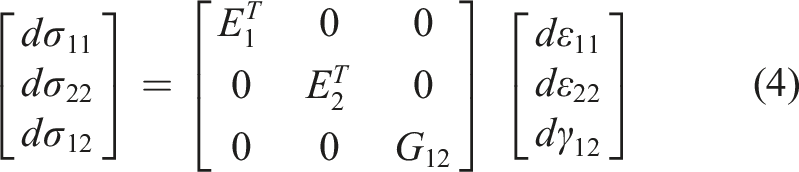
Non-orthogonality emerges as the material shears; this necessitates updating the material properties with respect to the new fibre orientations. Towards that end, a FORTRAN VFABRIC non-linear material subroutine was chosen. VFABRIC calculates and updates the incremental fabric stresses for the given incremental fabric strains. The constitutive equation for the material, following our assumption about the Poisson’s ratio, takes the form shown in equation (4).

The bending material model used S4 shell elements defined using the same nodes as the M3D4 elements in Abaqus. A single orthotropic lamina was used to define the material properties. The bending properties observed in the cantilever tests above are represented by an equivalent, average Young’s modulus along the fibre directions. Specifically, the mean of the orientations where the long fibres were orthogonal to the fulcrum (see Figure 5, cases 1–4) was used. This dictates the bending model cannot capture the through thickness anisotropy and instead the model homogenises the warp and weft bending stiffnesses in an isotropic bending model. A mean bending stiffness,
With these properties, a cantilever simulation was performed, similar to Ref. 3, where a bending angle of
A dynamic explicit analysis again was chosen to model the distributed magnetic clamping experimental procedure. This allowed for better contact stabilisation in comparison with a standard analysis and allowed the use of the Abaqus VFABRIC material subroutine. In pursuit of a model that could easily be adapted, a parametrised Python script was written that allows the user to modify many of the key variables. The magnets were modelled as analytical rigid parts with a mass equal to 35 g, a radius of 10 mm, a 0.5 mm fillet and a height of 5 mm. The penalty contact method was chosen, following a Coulomb friction model, with the magnets free to slide relative to the forming bed, whilst allowing the material to also slip. A coefficient of friction equal to 0.2 49 was used for all surface interactions, except for the interaction between the magnets and the veiled upper surface of the NCF – there 0.22 was used. The higher coefficient represents the higher frictional response of the magnet compacting the upper material surface. The model has two steps: the first initialises the clamping forces to promote numerical stability in the initial increment; the second step is the lowering of the tool, which emulates the tool stroke in the physical experiment for either geometry. With the natural time scale preserved, a small stable time increment could ensue due to the relatively small elastic modulus used for the shell elements impacting the wave speed propagation, thus fixed mass scaling was applied at 105. All simulations were terminated after 361 s, indicating successful draw. The simulations were run on the University of Bath’s high performance computing (HPC) service Balena, utilising 1 Intel Ivybridge node (7 cpus with 2.6 GHz).
Bayesian optimisation
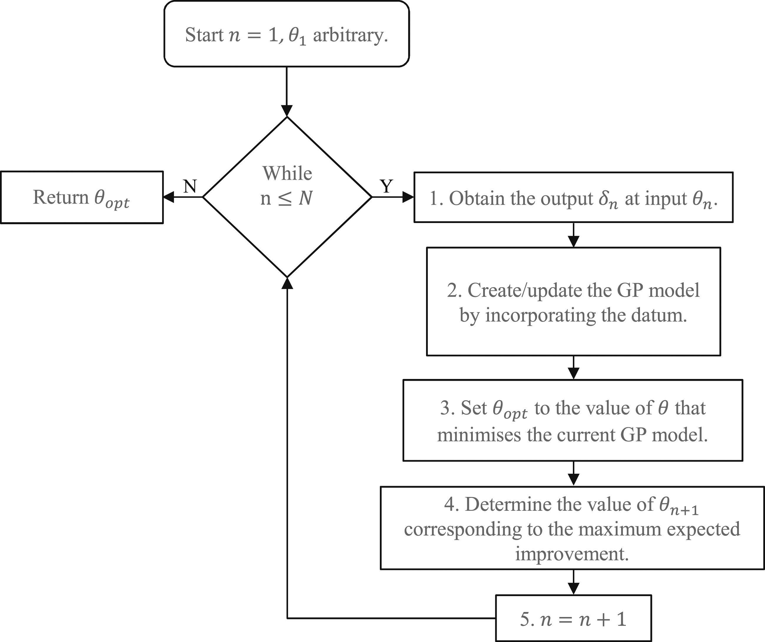
In this section, a brief introduction to Bayesian optimisation is presented. A more detailed background to Bayesian optimisation can be found in Ref. 31. This method is used in this paper to find the optimal magnet position. In a general Bayesian optimisation framework, the aim is to minimise a so-called black-box function, denoted by An example periodic Gaussian process model (top) and expected improvement (bottom). The mean of the distribution is represented by the black line and uncertainty by the green area, which denotes the 95% confidence interval for the value of the function. Flowchart of the Bayesian optimisation algorithm for finding 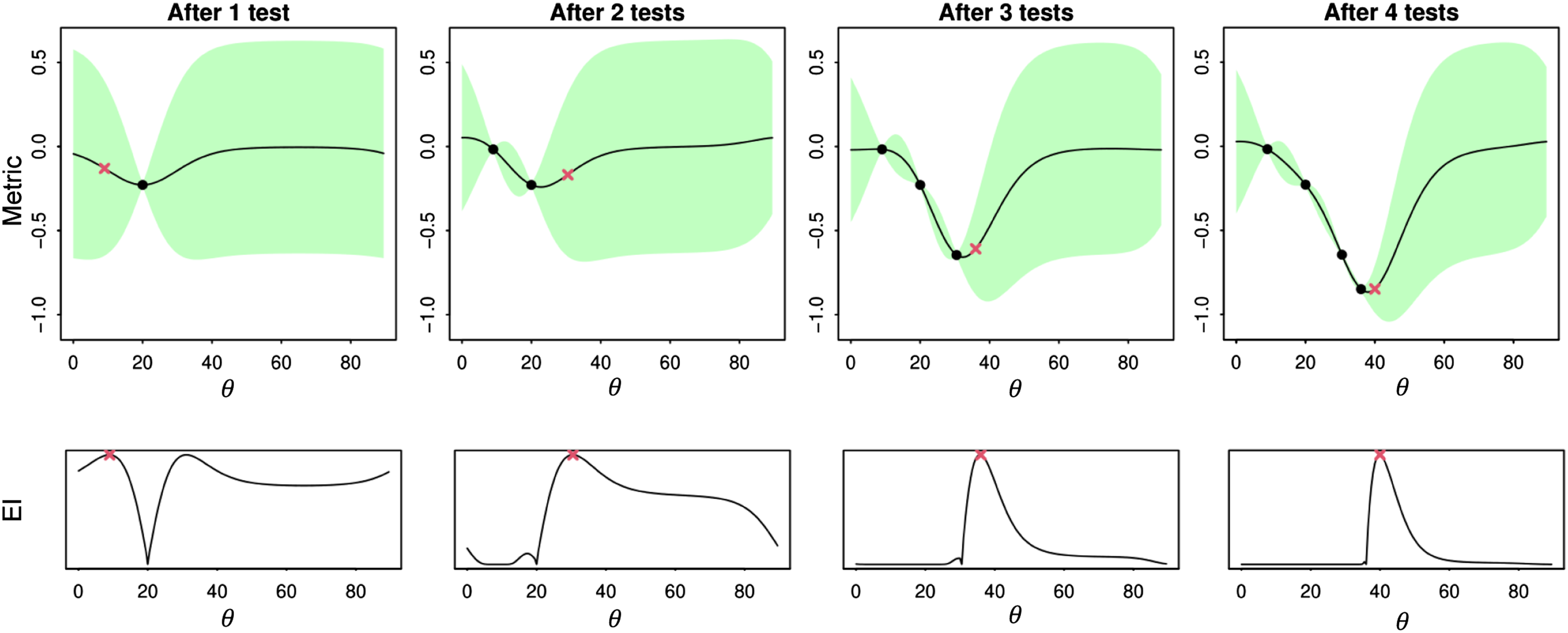
Gaussian process surrogate
A statistical model is a relationship between inputs
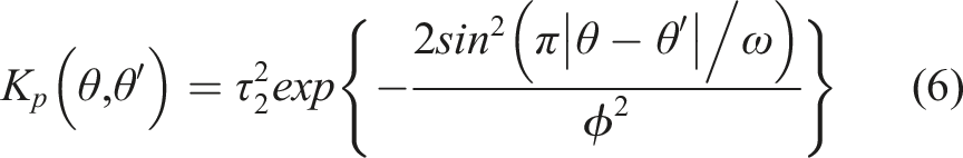
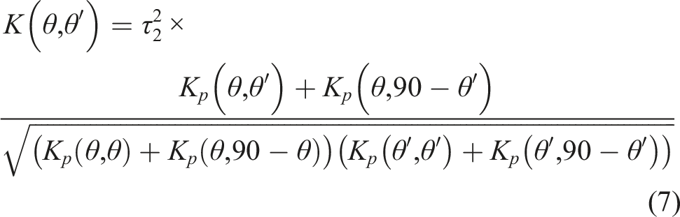
For the statistical model used in this paper, we set the noise standard deviation to
Bayesian optimisation process
Suppose

Here
In this work, the magnetic clamping process is treated as a black-box function, with the input
Results and discussion
Application of the distributed clamping process
For the hemisphere geometry (Figure 10 and Table 1), large wrinkles were mitigated when Hemisphere experimental results for three representative clamping configurations: (a) fibre mode with magnets at 0°, (b) shear mode magnets at 45°, (c) mixed-mode 22.5° showing the ‘s’ shaped twist steered fibres induced through tension shear coupling and slip. Oval magnifications show contrast enhanced inspection of major deformations. Colour maps show the distance of the material from the tool, δ. The top surface highlights the promotion of out-of-plane bending as an important forming behaviour. Experimental results of Note. pre-deformed material thickness is 1 mm.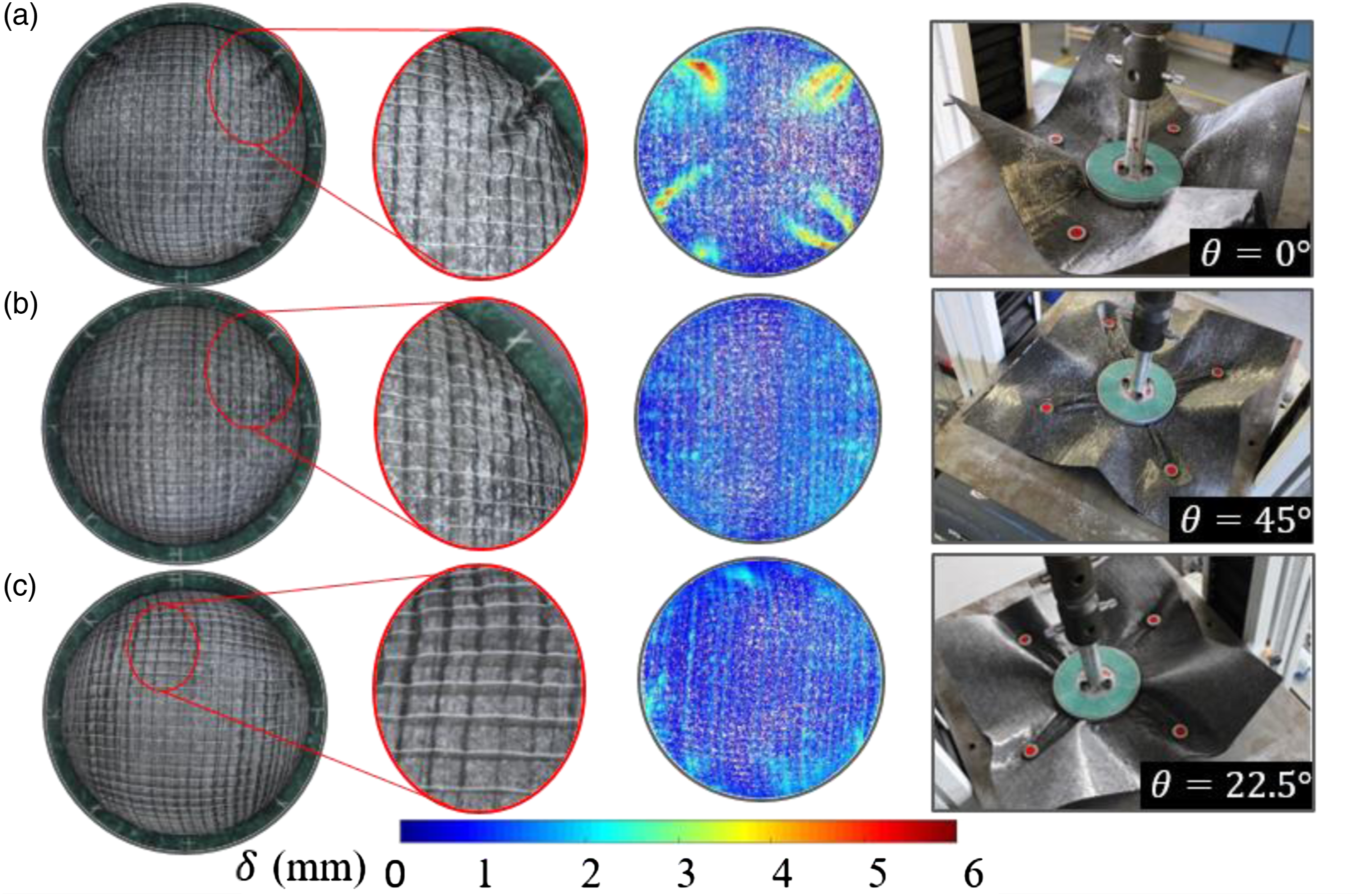
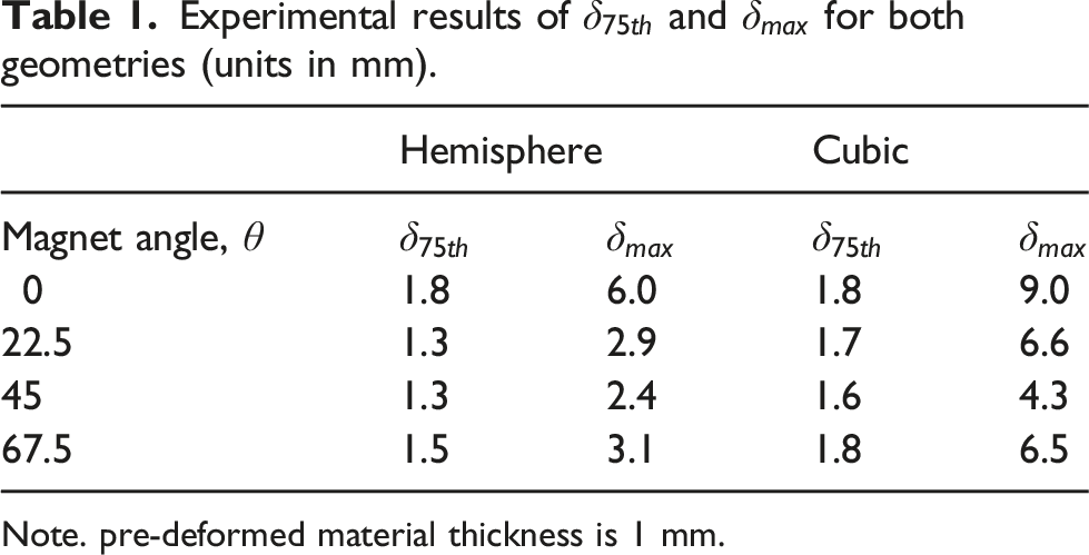
In the case of the cubic geometry, Figure 11 and Table 1, when Cubic experimental results for three representative clamping configurations: (a) fibre mode with magnets at 0°, (b) shear mode magnets at 45°, (c) mixed-mode 22.5° showing the twist induced through tension shear coupling and slip. Oval magnifications show contrast enhanced inspection of major deformations. Colour maps show the distance of the material from the tool, δ. The top surface highlights the promotion of out-of-plane bending as an important forming behaviour.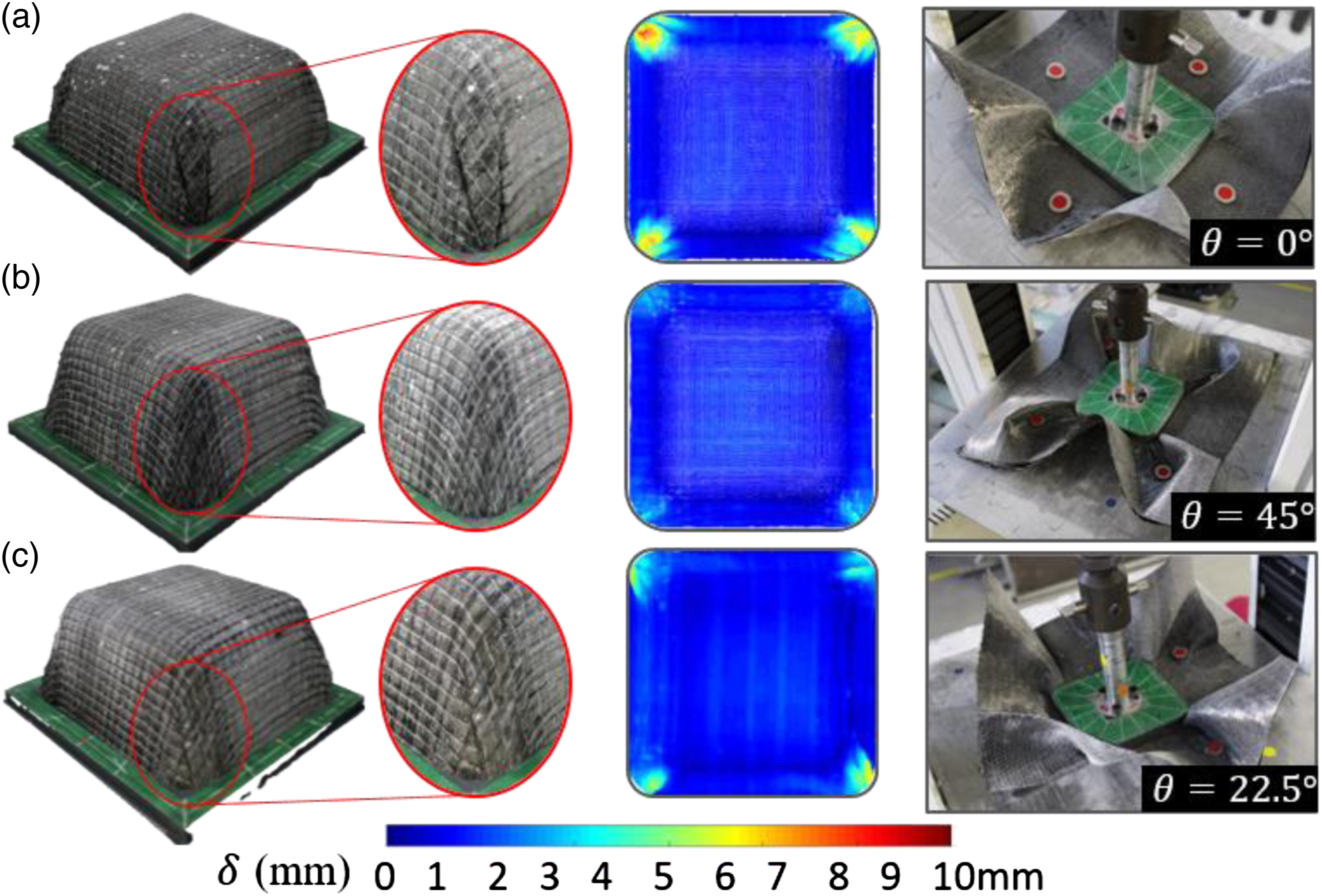
It is evident from the experiments that distributed magnetic clamping had a strong effect on forming for both hemisphere (Figure 10) and cubic geometries (Figure 11). In-plane radial tension was generated between magnetic clamps and points of contact on the tool. Tangential forces around each magnet were also present, however these seemed to be less dominant as they induce bending, which relieves the corresponding stresses. Magnetic clamping was also shown to control the material draw-through when activating the shear mode, (
Figures 10(c) and 11(c) show that in the mixed-mode experiments,
Abaqus process simulation
Axial force values, Comparison of experimental versus Abaqus results for axial force. Left, hemisphere tool when 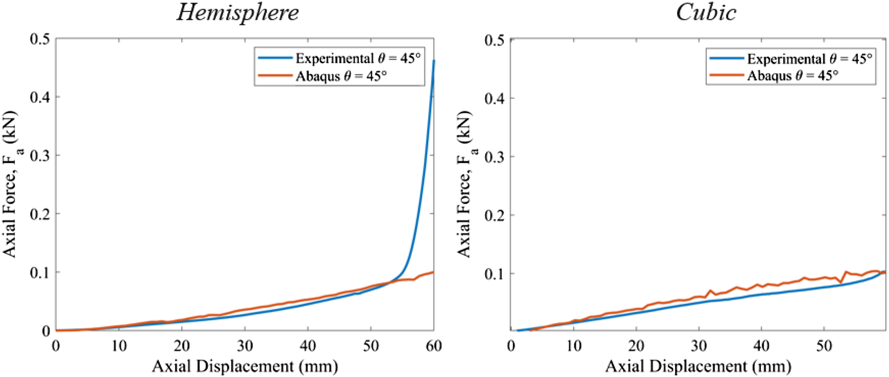
Comparison with the experimental results was undertaken for Left, comparison of wrinkle locations between experimental and Abaqus results. Right, magnified comparison when 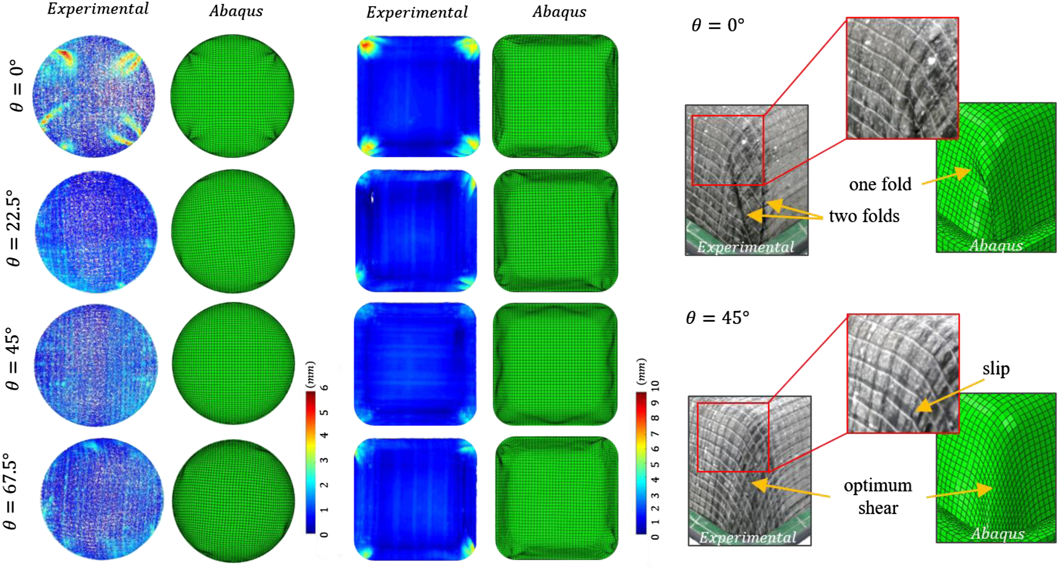
For the hemisphere, when Abaqus simulation results showing the shear angle distribution through the material for both the clamped surface and the target part. First magnet at (a) 45° and (b) 0° for the hemisphere, and (c) 45° and (d) 0° for the cubic.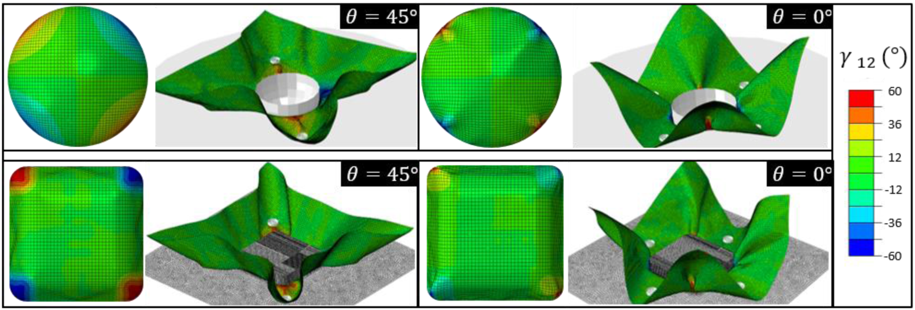
The in-plane shear stress results for the hemispherical tool configurations when Abaqus in-plane shear stress, 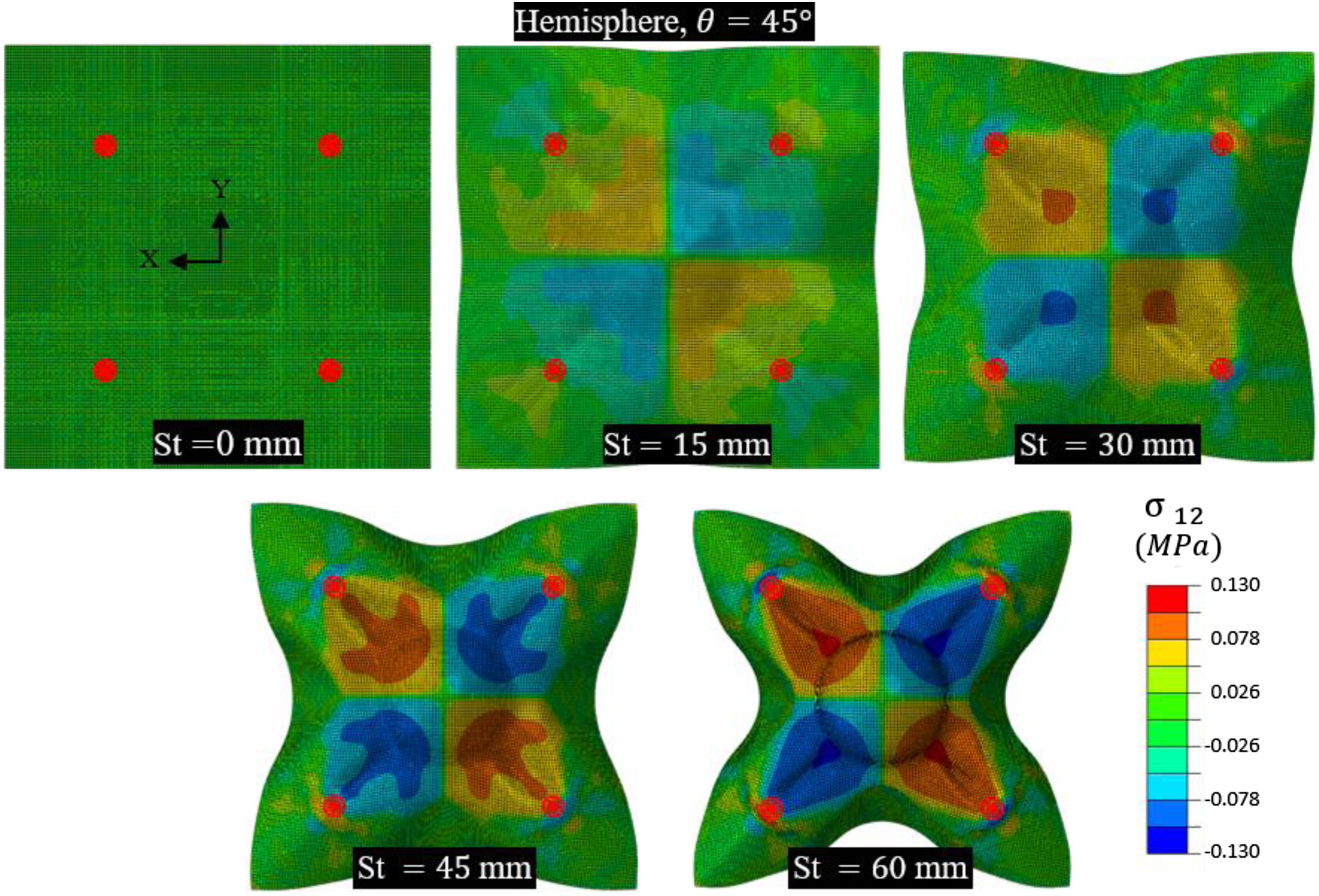
Application of Bayesian optimisation to the distributed clamping process
The optimisation procedure for the two geometries took 5.25 days (hemisphere) and 9 days (cubic) to complete nine simulations. The discrete rigid description of the cubic tool explains the increased computational demands. In Figures 16 and 17 it is noted that after five simulated experiments, both the cubic and hemisphere geometry results already exploit the area around Bayesian optimisation stages for the hemispherical tool using FE simulation results, Bayesian optimisation stages for the cubic tool using FE simulation results, 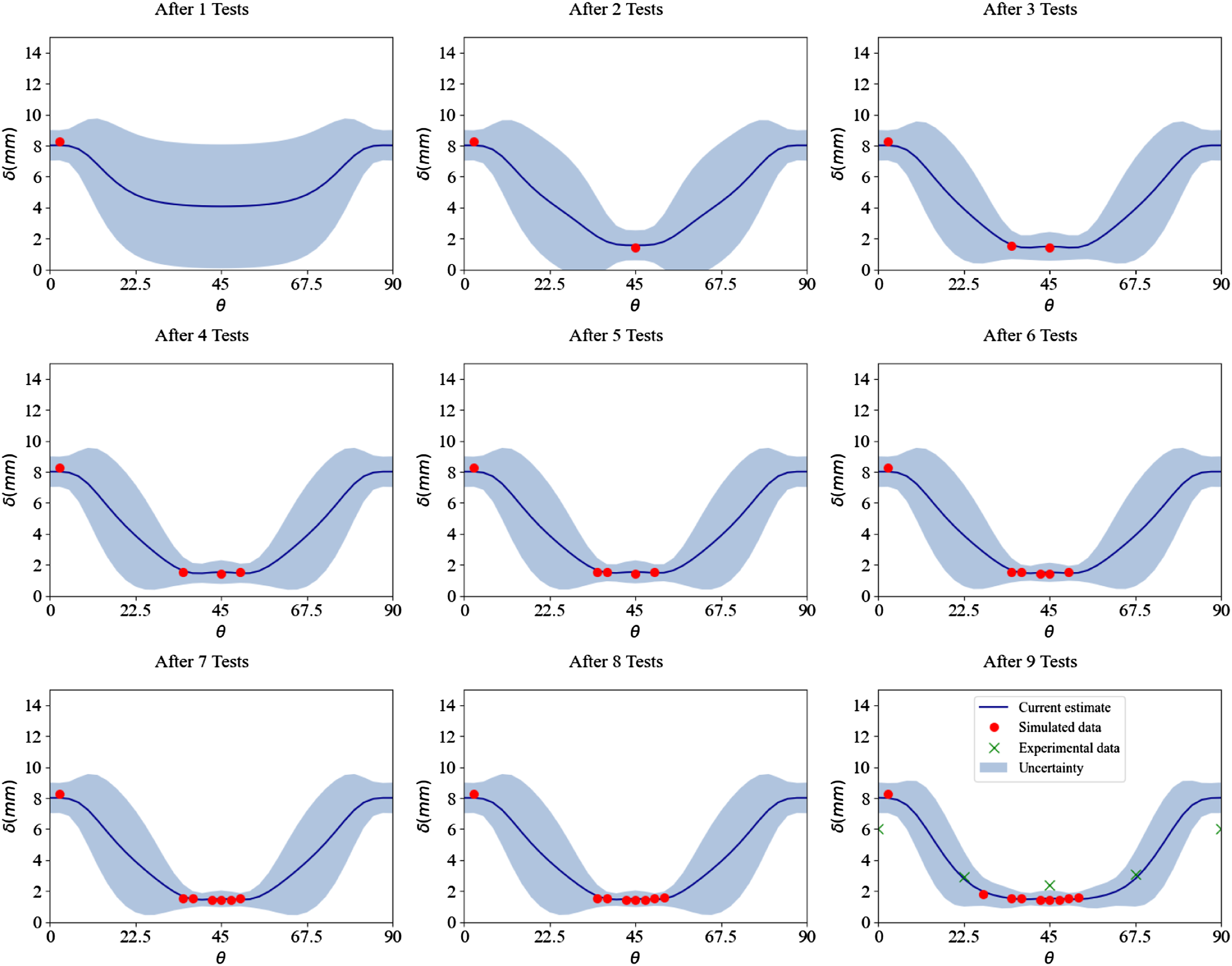
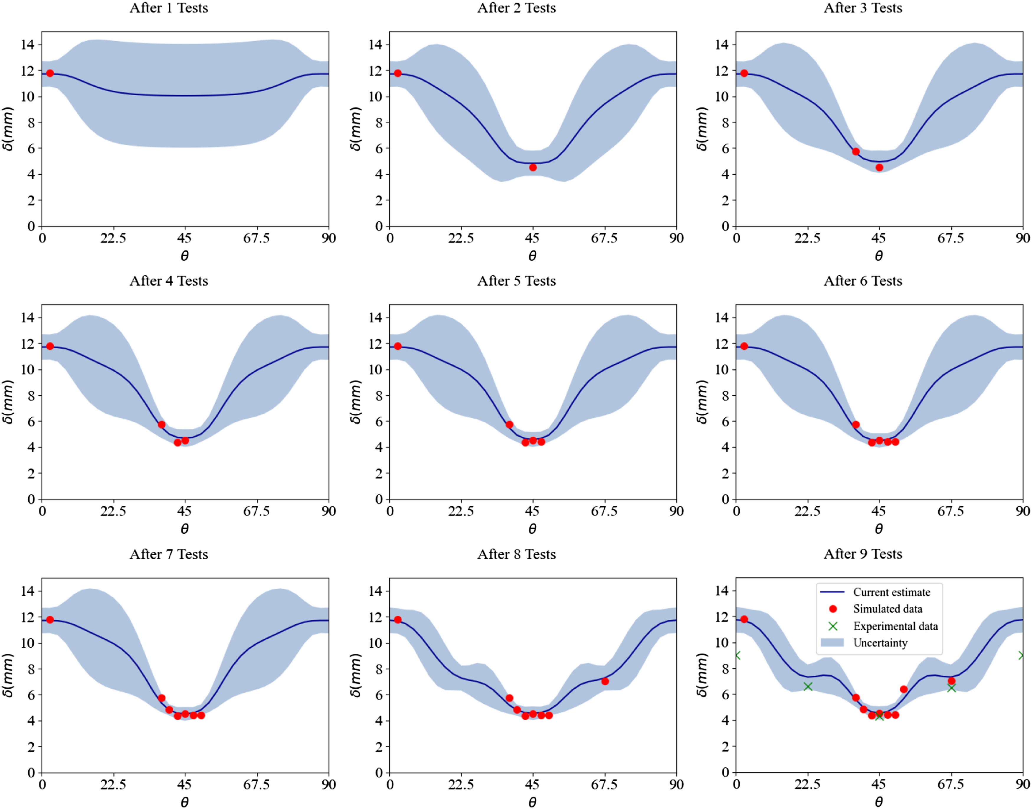
Figures 16 and 17 also illustrate
Discussion
Magnetic control was simple and flexible in application. By decreasing the variability in the manufacturing process, coupled with increasing the flexibility of boundary control, more translatable data sets can be built. Bayesian optimisation was presented here to highlight the ease of optimisation when using distributed clamping. This technique opens the door to more control with variables such as magnet position radius, number of magnets, magnet angle and magnet size. While these could be seen as increasing the search domain, feature segmentation could further simplify complex geometries, reducing the sampling burden and increasing diversity of data.
Whilst tools here were closed form and had at least four transverse planes of symmetry, magnets could readily be deployed to control shear deformation in parts such as aircraft secondary structures. Here, magnets could be used to control material-draw in around particular features by deploying specific magnet configurations. Magnetic constraints could also be used with matched tooling forming processes. Further, a variety of magnet shapes such as bar shaped magnets could allow control of large sections of fabric in drape forming.
While other process control measures exist, few offer the same ease of application. Here, a flexible process has been described. This will allow manufacturers and researchers alike to develop comprehensive training data banks, fuelling predictive modelling capabilities of the future.
Concluding remarks
Magnetic distributed clamping offered an efficient process control measure for forming positive Gaussian curvature parts. Providing an effective means of boundary control, with high levels of repeatability, in-plane magnetic constraints were effectively modelled and amenable to optimisation. Feature segmentation and feasible offline optimisation would however require further characterisation of the material mechanics. This study has therefore resulted in the following remarks. 1. Distributed magnetic clamping successfully induced in-plane tension to alter the deformation mechanics and highlighted the advantages of magnets for application in fabric forming. Promotion of out-of-plane bending in the material, because of discontinuous blank clamping, enabled a reduction in defects when the shear mode was activated. A complex cubic geometry with industrial applicability was successfully shown through experiment to have good material conformity. 2. The non-fixed non-stereo photogrammetry technique was successful at capturing the surface morphology of the material and allows further flexibility and evaluation of otherwise inaccessible regions and could be used in industrial settings. 3. Characterisation of the veiled biaxial NCF revealed complicated bending mechanics. The veil was shown to act as a stiffener in bending, with highly anisotropic bending properties. However, the efficient macroscale FEA strategy used in this study, with coupled idealised shell and membrane elements, remained a viable approach. 4. Gaussian process modelling of the amount of deformation, using a periodic kernel, and the use of Bayesian optimisation to find the optimal angle, were demonstrated. Results indicated that the magnetic distributed clamping process was amenable to surrogate modelling. However further statistical inference between metrics may be needed to reduce unexpected noise which results in local minima in more complex geometries. 5. This novel magnetic forming method allowed more flexible, scalable, and industrially relevant processing. The method would work with many existing processes and facilitates integration and extension of data sets.
Future research looks to explore the distributed magnetic clamping method with multiple plies, broadening industrial relevance, and to demonstrate the reduction in cycle times that could be attained. Magnetic clamps have been shown to offer broad possibilities that warrant future investigation including more complex geometries, fibre angle offsetting, magnetic clamping on the tool rather than the boundary, multi-stage variable clamping, active magnetic shear actuation and diverse magnet sizes. Such a process in combination with powerful non-parametric models may facilitate the creation of large databanks, leading to dramatically improved flexibility in design and manufacturing.
Footnotes
Acknowledgements
The authors would like to thank EPSRC and UKRI for supporting the work carried out under the National Productivity Investment Fund (NPIF) project (EP/R512424/1). Rajan Jagpal’s PhD studentship was 50% funded by GKN Aerospace. The authors would like to particularly thank GKN Aerospace for providing industrial context and guidance. This research made use of the Balena HPC Service at the University of Bath, and SEM preparation and training at MC2 under the guidance of Dr Philip Fletcher. Prof. Richard Butler also holds the Royal Academy of Engineering - GKN Aerospace Research Chair.
Declaration of conflicting interests
The author(s) declared no potential conflicts of interest with respect to the research, authorship, and/or publication of this article.
Funding
The author(s) disclosed receipt of the following financial support for the research, authorship, and/or publication of this article: This study is supported by Engineering and Physical Sciences Research Council (EP/R512424/1).