
Abstract
Recent demands for high-performance lightweight materials have brought researchers’ attention to various nanoparticles to reinforce polymeric materials. As such, sustainable and stiff cellulose nanocrystals (CNC) have become a popular candidate as nano-reinforcements. While CNC can offer great advantages, such as high mechanical properties and low density, it might agglomerate even in hydrophilic polymers because of its strong affinity to itself (intra and intermolecular hydrogen bonds) which prevents its broader use in industrial applications. This study aims to improve the compatibility between CNC and polyamide 6 (PA6) by a chemical modification that produces a surface polarity drastically different from non-modified CNC. The surface of CNC was rendered by the covalent coupling of stearic acid (SA) to the surface hydroxyl groups to produce stearate modified CNC (CNC SA). The effect of the modification was analyzed for CNC SA reinforced PA6 nanocomposites, and the results are compared to that of non-modified CNC reinforced PA6 samples. The addition of unmodified CNC to PA6 provided a modest improvement while the addition of CNC-SA provided substantial improvement on the modulus and tensile strength of the nanocomposite films.
Introduction
Carbon based nanomaterials (e.g., single-, double-, multi-walled carbon nanotubes, carbon black, and graphene) have been widely employed in nanocomposites due to their excellent mechanical properties. 1 However, the fabrication of carbon nanomaterials, their incorporation into nanocomposites and their disposal at the end of their useful life-cycle possess potential health and environmental challenges. 2 The composite materials research field, as well as commercial suppliers, have welcomed alternative reinforcing materials that are derived from renewable resources such as cellulose nanocrystals (CNC). In conjunction with renewability, CNC offer biodegradability, low cost, and considerably less potential health problems. Additionally, CNC also offer high surface area (150–600 m2g−1),3,4 high aspect ratio and attractive mechanical properties (approximate elastic modulus and tensile strength of up to 160 5 and 300 GPa, 6 respectively). Due to these attractive properties, there is a growing body of literature on the development of CNC reinforced nanocomposites. 7 There is a growing number of multinational companies related to polymer processing and polymeric products manufacturing industries that are paying considerable attention to CNC to improve their current products or to potentially use CNC in new polymers. Considerations for choosing CNC/polymer pairs and processing methods have recently been reviewed.8,9
The surface chemistry of CNC is naturally composed of polar hydroxyl groups as well as charged ionic groups resulting from the isolation process during the production of the CNC. 10 Thus, there are a large number of examples of CNC incorporation into various polar, hydrophilic polymers, such as polyvinyl alcohol, 11 polylactic acid, 12 polyethylene oxide, 13 polyurethane, 14 and starch. 15 Challenges, such as low thermal degradation and surface chemistry of CNC, have limited its use in thermoplastic matrices. The poor compatibility between CNC and hydrophobic polymer matrices generally result in agglomeration of the nanomaterial during mixing. 9 Strong inter-molecular hydrogen bonding induces self-aggregation of CNC even in the process of mixing with polar polymer matrices. 9 While attempts to mix CNC with thermoplastics such as polyethylene, 16 polypropylene, 17 poly (vinyl chloride), 18 polystyrene, 19 and polyamide 6 (PA6) 20 have been made, more work is necessary to further demonstrate and exploit the benefits of CNC reinforcement in non or less-polar polymers.
Polyamide 6 (PA6) is a thermoplastic polymer that is widely used in many industries and many applications such as food packaging, household goods, textile industries, and electrical industries 21 ; however, it has been the subject of very limited number of studies involving its reinforcement with CNC. Yousefian and Rodrigue reported compounding spray-dried CNC particles with PA6 using a thermal extrusion process at 220 °C. 21 They observed 23% and 11% increase in modulus and tensile strength with the addition of 3 w.% of CNC, respectfully. Thermal processing of composite materials is industrially relevant. 22 However, CNC is known to have a low thermal degradation temperature limiting its use in thermal processing with polymers such as PA6, which exhibits a relatively high melting temperature (Tm ∼ 220 °C). A study by Corrêa, et al. attempted to address the thermal compatibility of CNC in melt mixing processes. They showed that coating freeze-dried CNC with PA6 in formic acid improves the thermal stability of the CNC. Composites prepared by melt mixing/compounding the coated CNC and PA6 improved the mechanical properties. 23 The addition of 1 w.% CNC in the PA6 resulted in an increase of 45% in elastic modulus but resulted in a slight decrease in tensile strength. Both of the studies utilized non-modified CNC.
Despite the fact that thermal processing is more industrially relevant, solvent mixing techniques for composite production are commonly used in research labs and leads to exploring full potentials of nanoparticles. 8 Polymer composite films can be produced by techniques such as solvent casting and spin coating. Spin coating offers better control over the thickness and surface morphology of the films. Spin-coating has been used to produce modified CNC reinforced polylactic acid (PLA) thin films. 24 In the case of PA6, our previous study is the only research in which this technique was used to produce CNC reinforced PA6 thin films 25 ; however, spin-coated modified CNC reinforced PA6 films have not been investigated in the literature. Numerous pathways have been followed to modify CNC.26–29 The most common modifications to promote the adhesion between CNC and engineering thermoplastic polymers are acetylation, 30 esterification,31,32 etherification, 33 and cationic surfactants.33–42 Among the modifications mentioned above, esterification of CNC with fatty acids43,44 has been reported as an efficient way to improve both the thermal properties of the CNC 45 and the mechanical properties of the resulting composite. 46 The esterification of CNC with fatty acids has never been used to reinforce PA6 despite its global high volume use in the industry.
Consequently, the main objective of this study produce stearic acid (SA) esterified CNCs, incorporate different wt% of these modified CNCs into PA6 matrix, document the increase in the mechanical properties of the produced nanocomposites, and finally, compare the results to that of non-reinforced PA6 and nanocomposited produced with non-modified CNCs. This study will act as an important benchmark for exploring applications of CNC reinforced less-polar thermoplastic materials.
Experimental
Material
Sulfated CNC was provided by InnoTech Alberta (Edmonton, AB, Canada). It was produced by sulfuric acid hydrolysis of a commercial bleached softwood Kraft pulp. Stearic acid SA (C18, 99%), dichloromethane DCM (99.5%), chloroform CHCl3 (99.5%), trifluoroacetic anhydride TFAA (99%), toluene (99.9%), and formic acid FA (98%). Polyamide 6 (PA6) with density of 1.084 g/ml 25°C (25038 54-4) was purchased from Sigma Aldrich and used as received. Analytical grade chemicals and solvents were used as received, without further purification.
Synthesis of cellulose nanocrystal stearate
In the esterification treatment, cellulose nanocrystal stearate (CNC-SA) was synthesized following the method described by Huang,
46
with a slight modification as shown in Figure 1. SA and TFAA (molar ratio of acid to TFAA was 1.1; 1.0) were mixed in a 500 mL three neck flask equipped with a condenser and stirred gently at 50°C for 20 min to form mixed acid anhydride. Spray-dried CNC powder (molar ratio of TFAA to AGU (anhydroglucose unit) was 3.3:1.0) was added to this solution and stirred mildly at 50°C for 6 h. The reaction mixture was then poured into an excess amount of ethanol, and the precipitate was filtered and washed with methanol (50 mL per gram of CNC) three times at 60°C. Then, soxhlet extraction with ethanol was carried out for 24 h. Finally, CNC-SA was dried at 50°C for 24 h under vacuum. Esterification process of CNC.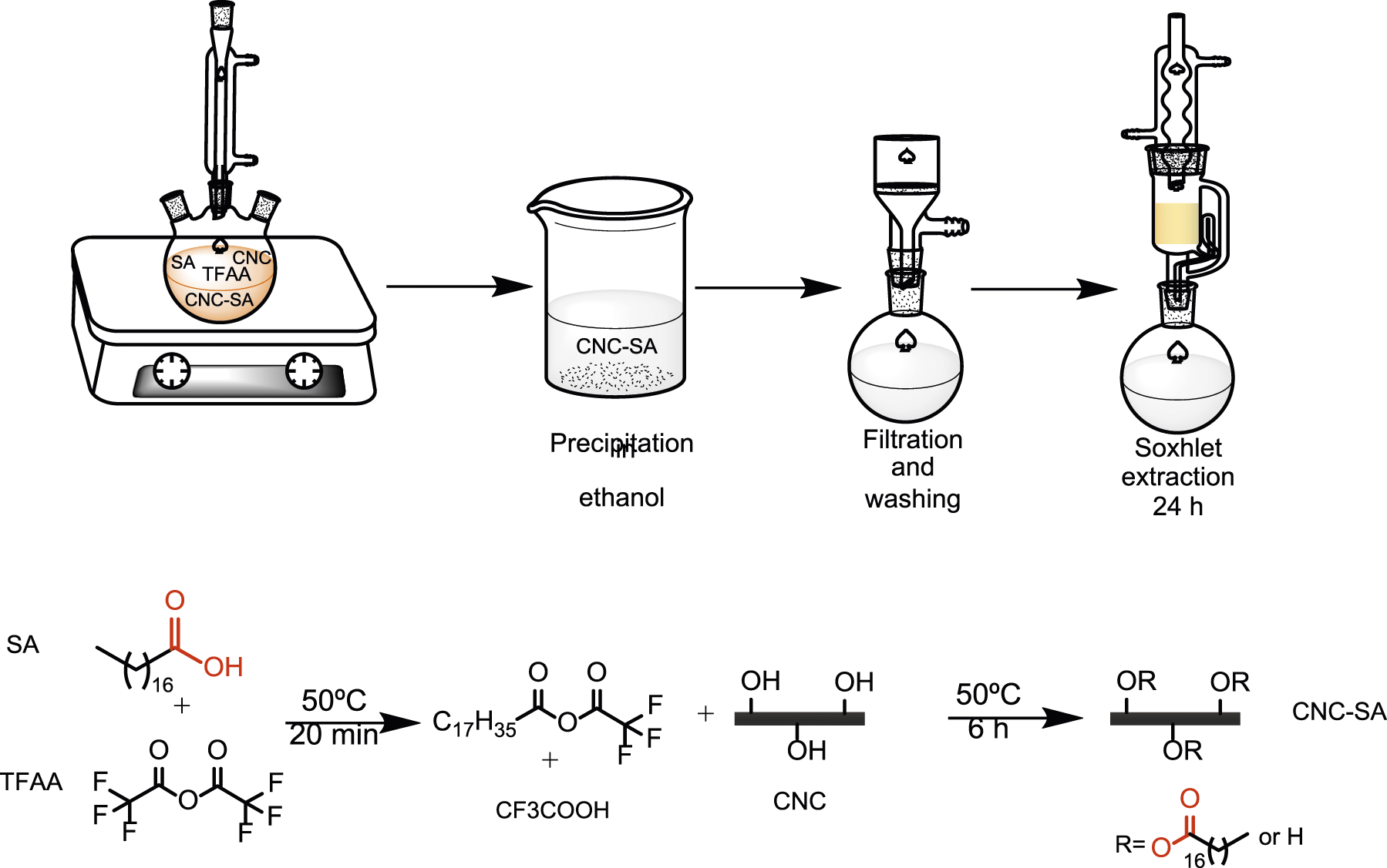
Thin film preparation by spin-coating method
Spin-coating technique is based on the removal of the liquid phase by applying high-speed spinning, which allows users to create reproducible thin films. For preparation of the suspension, it is necessary to use a solvent that evaporates quickly at room temperature. In the case of unmodified CNC, formic acid (FA) was used as a solvent. However, it was difficult to obtain a good dispersion of CNC-SA in formic acid; therefore, a mixture of dried dichloromethane (DCM) and TFAA (volume fraction of TFAA to DCM was 30:70) was used to disperse CNC-SA in PA6. Briefly, CNC and PA6 were dried at 50°C and 80°C, respectively, for 24 h to eliminate moisture. The 100.0, 99.0, 97.5, and 95.0% (w/w) of PA6 were dissolved and then CNC or CNC-SA (depending on the solvent used) were added and stirred at 24°C overnight under continuous agitation.
For spinning, 2 mL of the suspension was placed on a rectangular-shape glass substrate (with a length and width of 75 and 25 mm, respectively) and accelerated to 2000 rpm for 15 s and spun at 3000 rpm for 30 s. After the total 45 s of spinning, the apparatus was stopped and the film was left for several minutes for any potential remaining solvent to evaporate. Finally, the spin-coated films were dried overnight in a vacuum desiccator before being mechanically tested. The experimental setup is shown in Figure 2. Overview of the experimental setup: solvent mixing (a), CNC PA6 and CNC-SA PA6 suspensions in vials (b), spinning of suspensions on glass substrate (c), magnified view of the rotary plate (d), a spin-coated thin film (e), and the samples cut into strips prior to the tensile tests (f).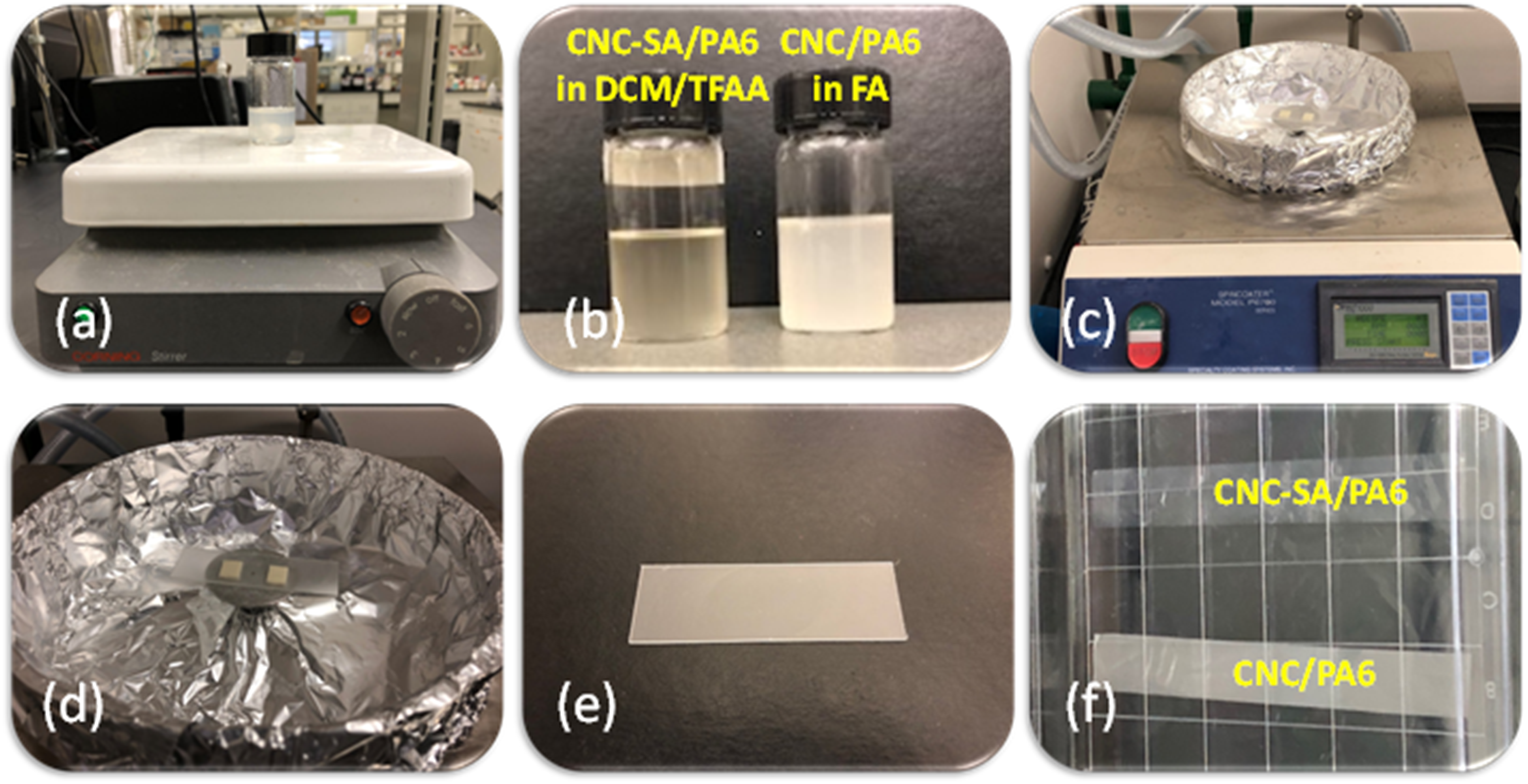
Composition of the produced films with coding.
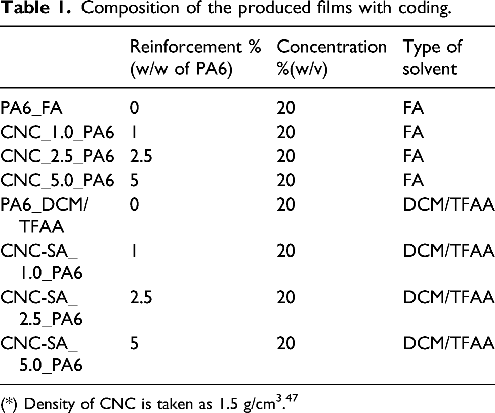
(*) Density of CNC is taken as 1.5 g/cm3. 47
Characterization
Fourier transform infrared spectroscopy
Fourier transform infrared spectroscopy (FTIR) spectra were collected using Nicolet 8700 FT-IR spectrometer in trans-mission mode. 1 mg of dried sample and 100 mg KBr powder were grounded together using a mortar and pestle and pressed to form discs. A total of 32 scans were taken per sample with a resolution of 4 cm−1 (4000–800 cm−1).
Elemental analysis (CHNS)
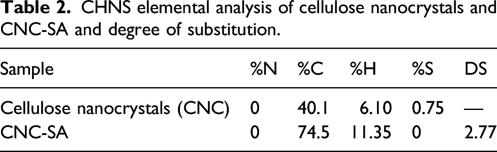
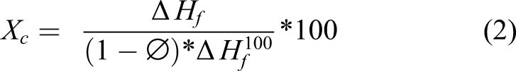
The degree of substitution (DS) of CNC-SA was measured using the percentage of carbon (%C). The %C was measured using a Thermo Flash 2000 Elemental Analyzer CHNS and Oxygen. The DS of CNC-SA was calculated based on the equation (1)
32

X-ray photoelectron spectroscopy
X-ray photoelectron spectroscopy measurements were performed with a Kratos Ultra electron spectrometer (Kratos Axis Ultra) using a monochromatic Al Kα (hν = 1486.6eV) X-ray source (Kratos Analytical, Manchester, UK). The collected data were analyzed using Vision software version 2.1.3 and CASA XPS version 2.3.
Contact angle measurement
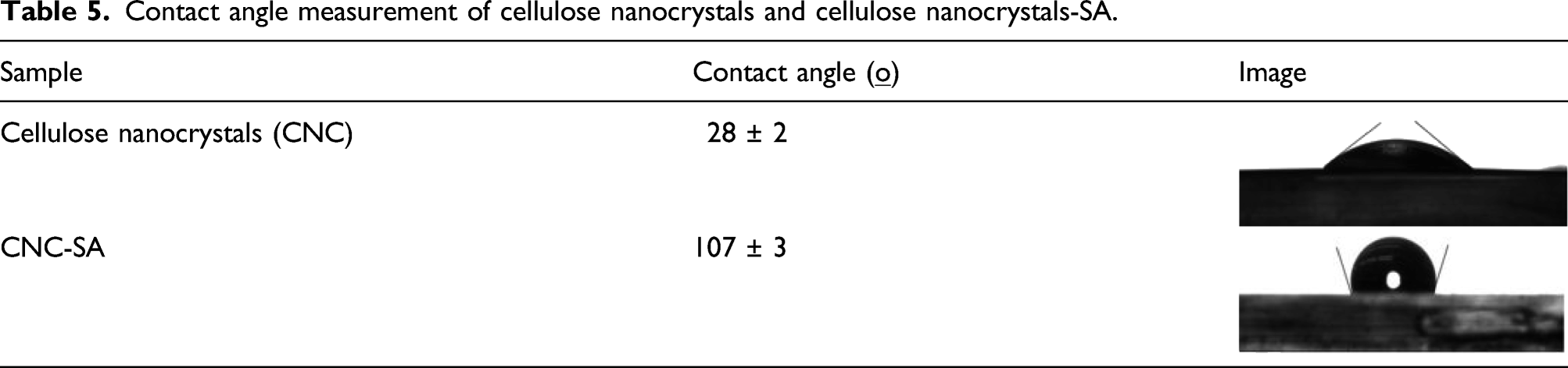
Contact angle measurements have been carried out at room temperature on CNC films before and after modification in order to determine the change in wettability. The water sessile drop CAM were carried out on our substrates using a Rame-Hart goniometer (model 590) equipped with a CCD camera. All measurements were performed three times for each sample. The samples were prepared by dispersing a known amount of CNC and CNC-SA in DI water and toluene, respectively. The obtained suspensions were then solvent cast in rectangular glass substrates, previously cleaned with piranha solution to avoid any possible contamination. The samples were dried overnight in a vacuum oven at 100 ºC. Finally, samples were kept in a desiccator for 30 min before contact angle measurements.
Differential scanning calorimetry
Thermal analysis of the nanocomposites and neat PA6 were carried out in a TA Instrument DSC Q2000 under nitrogen atmosphere. The samples (2–5 mg) were placed in hermetic aluminum DSC pan and heated from 25°C to 250°C at a heating rate of 10°C/min.
Transmission electron microscopy
Philips 410 transmission electron microscope was utilized at 100Kv to observe the morphology of pure CNC and modified CNC. In addition, the nanocomposites were also investigated under TEM. Two different sample preparation protocols were followed for particles and composites.
For the particles, CNC were dispersed in water, and 0.5 ml of solution was dropped on a TEM copper grip. Excess solution of CNC was removed from the grid and remaining CNC was investigated.
For the nanocomposites, prepared samples first embedded into epoxy and then were microtomed by using a glass knife in a Reichert-Jung Ultracut E ultramicrotome. The microtomed samples were double-side stained with uranyl acetate for 2.5 h and lead citrate for 1 h before TEM analysis.
Scanning electron microscopy
The SEM images of typical samples were obtained with Zeiss Sigma FESEM w/EDX & EBSD Scanning Electron Microscope. Samples were coated with carbon with a thickness of 6nm by Leica ACE600 Carbon/Metal coater. The SEM operating voltage was at 0.5 kV.
Uniaxial tensile test
Mechanical tests were performed using TA instruments (ElectroForce 3200), with a 10 N capacity load cell. The specimens were prepared by using a custom-made 3D printed cutting plate that allows a rotary cutter to cut specimens. The blade cut was done with one pass on each side of the film to obtain a sample with defect-free edges. Sample dimensions were 10 mm and 75 mm for width and length, respectively. Grips hold 25 mm total of the samples; thus, distance between the grips (gage length) was 50 mm. Samples were stored overnight in desiccators containing silica gel before testing. A C-shaped mechanical testing frame (paper frame) was used to hold the sample and prevent sliding of samples between grips. It also helps with reduction of stress concentration, forming at the grips. The frame was cut prior to the test to ensure only samples were tested. All experiments were carried out at room temperature with a strain rate of 0.1 mm/min (5 mm/min) and the results were averaged.
Results and discussion
Fourier transform infrared spectroscopy
The modification of CNC to yield a less polar, more hydrophobic surface involved the tethering of long aliphatic chains from the surface functional groups. This has been accomplished previously in the literature via the esterification of surface hydroxyl groups with either acid chlorides
32
or fatty acids.
45
Building upon this work, steric acid (SA) was coupled to surface hydroxyl groups via an esterification reaction initially reported by Huang et al.
46
Vibrational spectroscopy is a useful tool for the characterization of cellulose materials including CNC.
48
Infrared spectroscopy (IR) is commonly applied to monitor chemical modification of CNC.
49
Figure 3 shows FTIR spectra of unmodified CNC and CNC-SA. The spectrum of the unmodified CNC is consistent with those in the literature (50, 51). The collection of bands between 800 and 1200 cm−1 are associated with a variety of C-O vibrations. The band at 1620 cm−1 and the broad band at 3370 cm−1 are assigned to water adsorbed on the surface of CNC and hydroxyl groups, respectively. The spectrum of CNC-SA contains bands that confirm the coupling of SA to the CNC through an ester bond and is qualitatively similar to spectra for similarly modified CNC.
32
The primary evidence is the appearance of the band at 1740 cm−1 that can be assigned to the carbonyl stretch of an ester moiety. Also, bands corresponding to a significant increase in –CH2– groups are observed. The pair of bands at 2910 and 2850 cm−1 correspond to the symmetric and asymmetric –CH2– stretch and the band at 1470 cm−1 is due to –CH2– bending. Also, a weak peak of adsorbed water was observed in the CNC-SA spectrum, as expected for a more hydrophobic material. In addition, for CNC-SA, the band at 3370 cm−1 completely disappeared, indicating that the total number of OH groups on the surface of CNC were substituted. FTIR analysis provides strong support for the modification of CNC with SA via esterification. FTIR results of cellulose nanocrystals (CNC), and cellulose nanocrystals stearate (CNC-SA).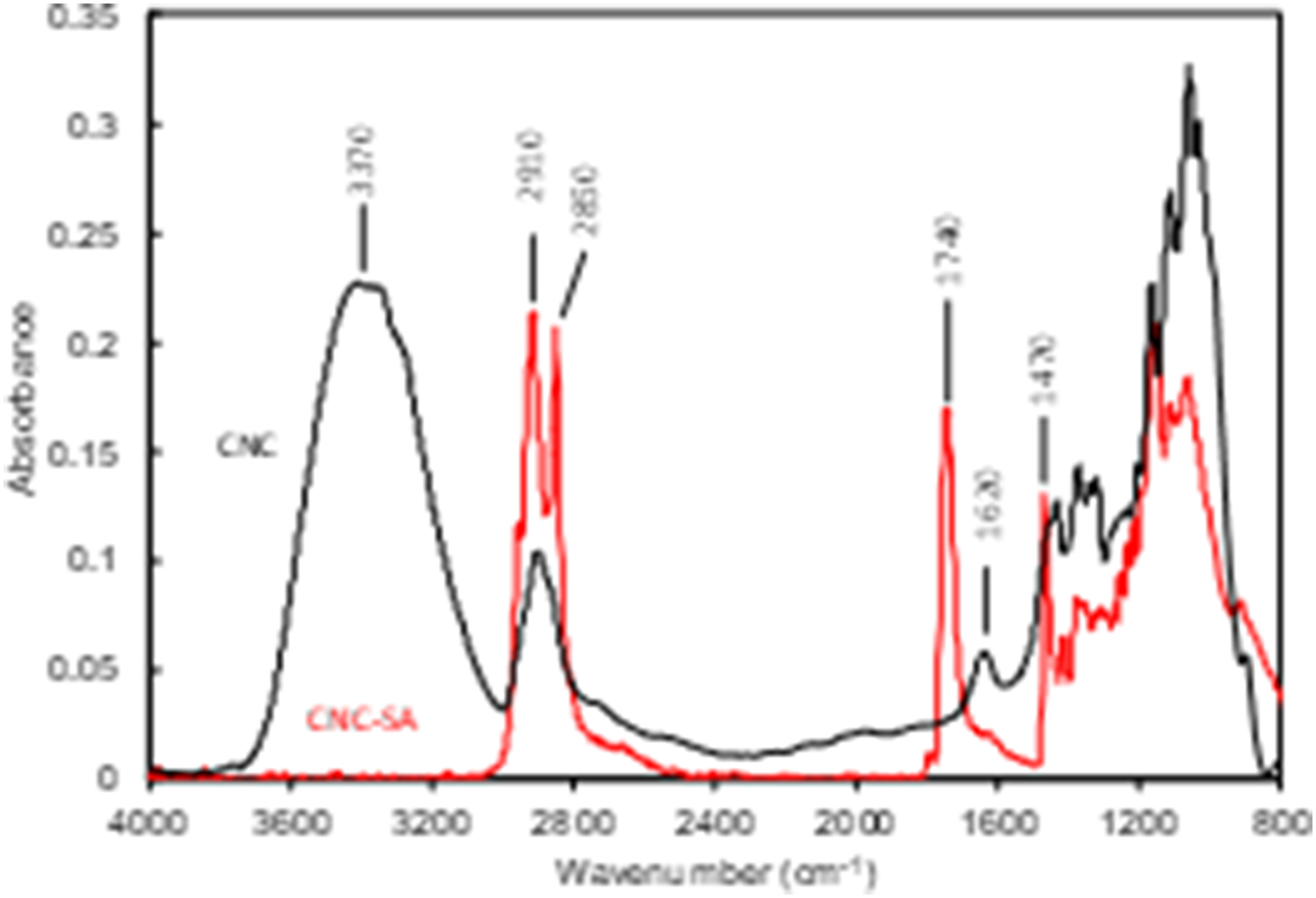
Elemental analysis
X-ray photoelectron spectroscopy
Atomic composition of CNC and CNC-SA from XPS survey spectra.
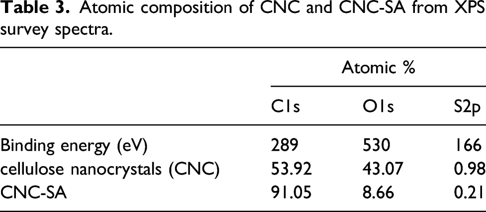
High resolution XPS spectra for the C1s signal provides the details of the different carbon bonding patterns. Figure 4 displays the high-resolution XPS spectra in the C1s region. The signal was fitted for the four components that are expected, aliphatic carbon (C1), C–O (C2), O–C–O (C3), and O–C = O (C4). The percentages of the total peak area of each component are listed in Table4. High-resolution XPS spectra of the C1s signal of CNC (a) and CNC-SA (b) and deconvolution of each contributing species. Carbon type composition in terms of % of total peak area of cellulose nanocrystals and CNC-SA from high-resolution X-ray photoelectron spectroscopy.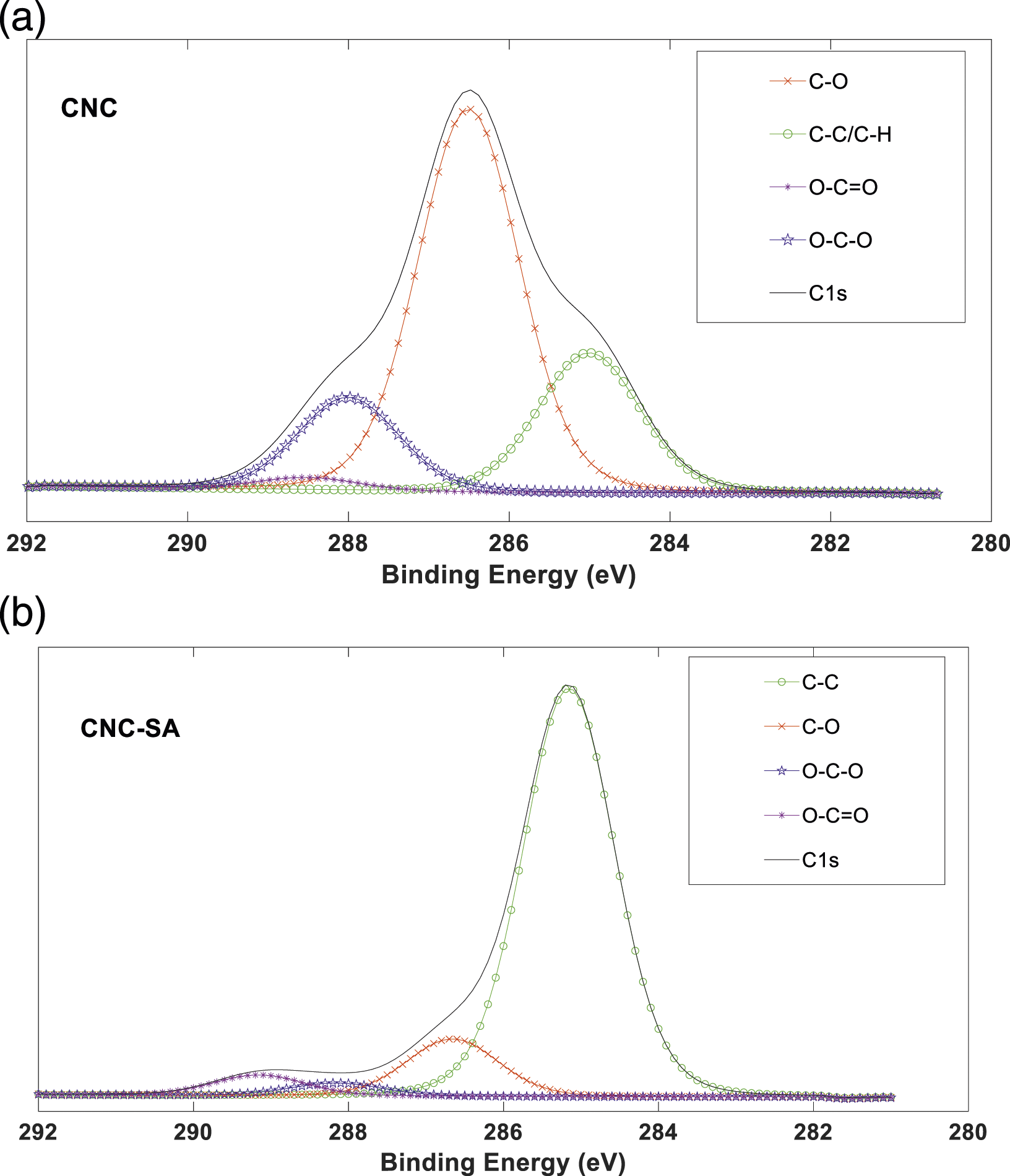

Unmodified CNC should only exhibit C2 and C3 contributions. We attribute the C1 and C4 contributions observed for our unmodified CNC as impurities, possibly lignin from the processing. Following modification with SA both the C1 and C4 contributions to the total peal area increase remarkably, as expected. An estimation of the degree of substitution as reported by Bendahou et al. 32 yields a value slightly over 100%. A gravimetric estimate of the grafting efficiency yields a value of 80% (w/w). Both the FTIR and XPS characterization show that the esterification reaction in Figure 1 effectively couples aliphatic chains to the CNC surface in high coverage.
Contact angle measurement
Contact angle measurement of cellulose nanocrystals and cellulose nanocrystals-SA.
The processing of CNC and CNC-SA reinforced PA6 films by spin coating required different solvent choices due to the vast differences in hydrophobicity of the nanoparticles. For optimal mixing, both the polymer and the CNC should be well dispersed in the same solvent. Formic acid (FA) is a typical solvent used to process PA6, especially for electrospinning [52, 53] and spin coating process.
54
Figure 5 shows photos of the CNC and CNC-SA dispersed in a range of solvents. As shown in Figure 5 (a), CNC disperses reasonably well in FA. On the other hand, due to its hydrophobic nature, CNC-SA disperses well in solvents such as toluene, chloroform, and solvent mixtures like dichloromethane (DCM/TFAA) as shown in Figure 5 (b). In addition, it has previously been shown that DCM/TFAA is a good solvent system for PA6.
55
The photos in Figure 5 (c) qualitatively shows the dispersion of CNC and PA6 in FA, and CNC-SA and PA6 in DCM/TFAA. Thus, considering feasible dispersion of both nanoparticle and polymer, CNC PA6 films were processed in FA, whereas CNC-SA PA6 films were processed in DCM/TFAA. The photos of CNC and CNC-SA in water and formic acid (a), CNC-SA dispersed in Toluene, DCM and chloroform (b), and CNC-SA with PA6 in DCM/TFAA and CNC with PA6 in formic acid (c).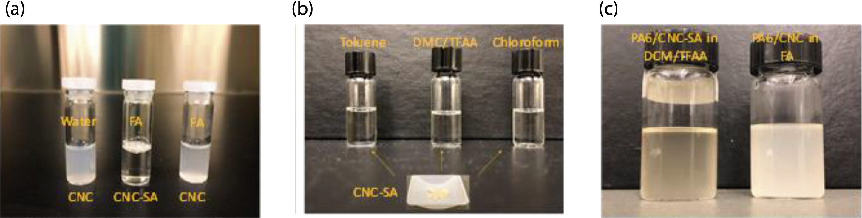
Differential scanning calorimetry
The thermal analysis of neat PA6 pellets, neat PA6 thin films, and their nanocomposite samples (5 w% CNC PA6 and 5 w% CNC-SA PA6) were characterized by DSC to assign crystal types and their percentages. DSC curves of various samples are shown in Figure 6. DSC heating curves of (a) unprocessed PA6 (b) neat PA6 previously dissolved in FA (c) neat PA6 previously dissolved in TFAA/DCM (d) 5.0 w% CNC PA6, and (e) 5.0 w% CNC-SA PA6.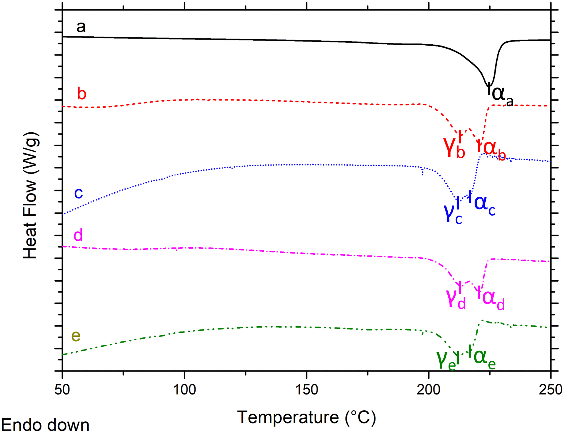
Summary of differential scanning calorimetry results.
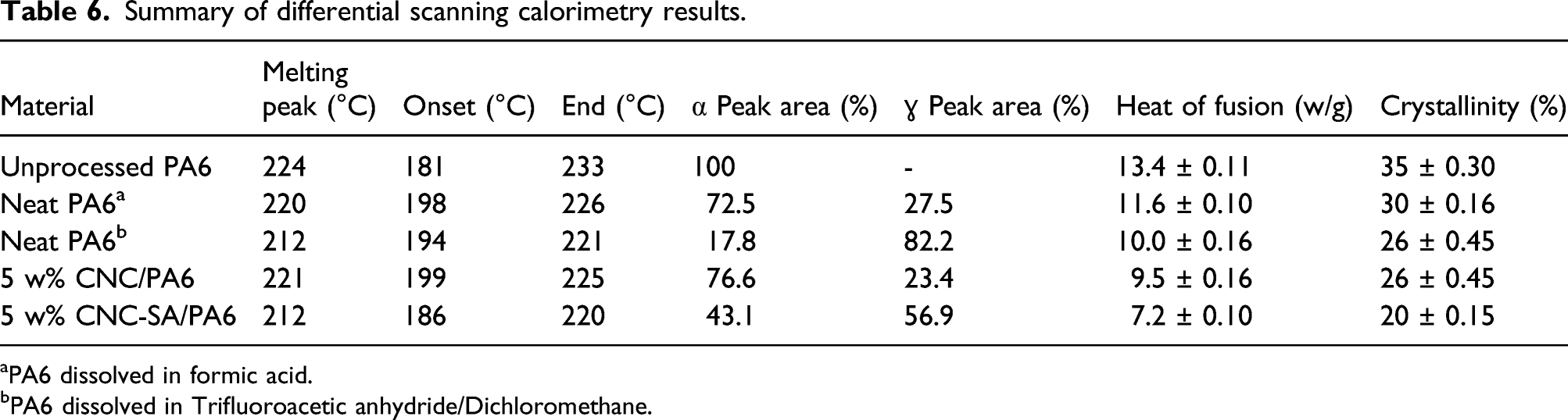
aPA6 dissolved in formic acid.
bPA6 dissolved in Trifluoroacetic anhydride/Dichloromethane.
The thermal analysis clearly indicates that the degree of crystallinity has been impacted by the spin coating process. In fact, the solvents used and the incorporation of reinforcements clearly reduce the heat of fusion, as shown in Table 6, which resulted in a decrease of crystallinity.
When degrees of crystallinity of neat PA6 are compared, a noticeable decrease is observed compared to that of neat PA6 pellets. The degree of crystallinity decreased from 35 to 30 when PA6 a is spin coated. However, in the case of neat PA6, b the degree of crystallinity significantly decreased from 35 to 26. As discussed in a previous study study, 55 the reaction of TFAA with hydrogen bonds of PA6 in dry DCM leads to the dissociation of hydrogen bonds between PA6 chains and lower crystallinity.
Similar trends were observed for the reinforced samples (5 w% CNC and CNC-SA PA6) compared to unprocessed PA6. A clear decrease of the degree of crystallinity was observed and this decrease was more significant when PA6 is blended with CNC-SA (from 35 to 26 for 5 w% CNC reinforced PA6 and from 35 to 20 for 5 w% CNCSA reinforced PA6).
Transmission electron microscopy
Transmission electron microscopy (TEM) was used to confirm the CNC structure after modification and to observe the distribution of CNC and CNC-SA within the PA6 matrix. Parts a and b of Figure 7 are TEM images of CNC and CNC-SA, respectively, where the samples were drop cast from water onto the TEM grid. The image of unmodified CNC (Figure 7(a)) reveals several individual particles and some longer aggregates. The features in Figure 7(a) range in diameter from 5 to 20 nm and in length from 100 to 400 nm. We expect that the lower measurement of these ranges to correspond to individual CNC particles. Figure 7(b) reveals larger aggregates of CNC-SA that likely arise due to hydrophobic interactions in the water solvent used to cast the sample. Despite the aggregation, individual CNC particles can be observed within an aggregate. The CNC particles retain their rod like shape after modification with SA suggesting that the procedure does not degrade the particles. These images suggest that both CNC and CNC-SA are both rod-like particles but with vastly different surface chemistry. TEM images of drop cast CNC only (a, b) and sectioned PA6 samples (c–e). (a) Unmodified CNC, (b) CNC-SA; (c) neat PA6 film; (d) 5 w% CNC reinforced PA6 film; (e) 5 w% CNC-SA reinforced PA6 film. The circles in parts d and e identify the CNC and CNC-SA incorporated into the PA6 matrix (see text).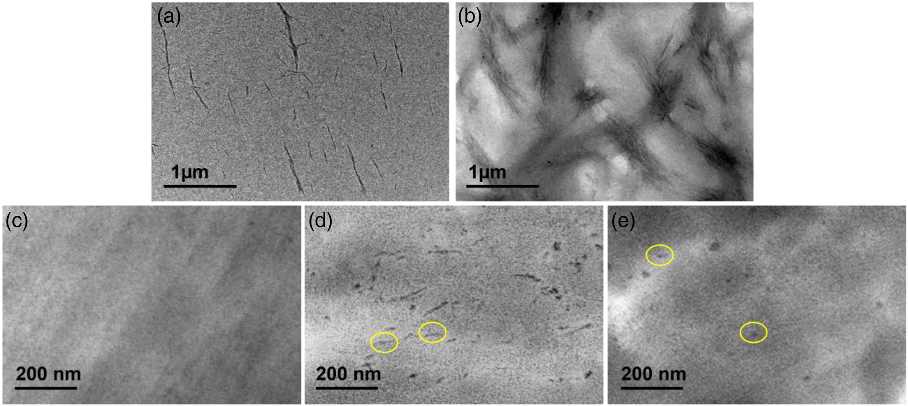
Parts c-e of Figure 7 are TEM images of sectioned and stained PA6 samples. Figure 7(c) is neat PA6 and shows a uniform morphology with no evidence of CNC. Figure 7(d) is an image of PA6 containing 5wt% CNC. Dark circular and rod-like features are observed distributed throughout the bright field image with two of these highlighted with circles. We believe these features are CNC that are differentially stained relative to the PA6 matrix causing the CNC to scatter more of the electron beam. The image of CNC-SA in PA6 (Figure 7(e)) contains darker irregular shaped features. Rod-like structures are not apparent in this image. Comparison of part c with part e leads us to conclude that the circular features in Figure 7(e) indicated with the circles are CNC-SA. We surmise that the different surface chemistry of CNC and CNC-SA leads to differences in staining density and the differences seen between parts d and e in Figure 7. Based on these images we conclude that the CNC and CNC-SA are both incorporated into the PA6 in our solvent mixing process and both are reasonably well-dispersed in the polymer matrix.
Scanning electron microscopy
Scanning electron microscope (SEM) was employed to understand more about surface morphology and the correlation between the structure and property of the thin films. SEM images of PA6, CNC reinforced PA6 (5.0 w%), and CNC-SA reinforced PA6 (5.0 w%) thin films are shown in Figure 8. The surface of the neat PA6 film in Figure 8 (a) and CNC reinforced PA6 film in Figure 8 (b) are relatively rough and consist of spherical shapes. This roughness is more significant in the case of neat PA6. This is consistent with the findings reported by Teodorescu et al. for spin coated films of pure PA6 that exhibited a similar film morphology.
54
In the case of CNC-SA reinforced PA6, the surface of the film is smooth compared to these of neat PA6 and CNC reinforced PA6 films. SEM photographs of Neat PA6 (a), 5 w% CNC reinforced PA6 (b), and 5 w% CNC-SA reinforced PA6 (c).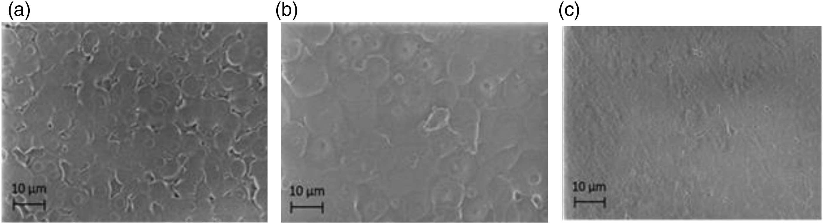
Unlike the TEM results, the observation of the fibers (CNC or CNC-SA) within the matrix is not obvious using SEM. This is in agreement with a study reported by Aitha et al. 59 where CNC reinforced PA6 nanocomposites were produced by solvent casting followed by melt pressing. It is worth noting that surface morphology of the materials is strongly controlled by several factors such as raw materials and manufacturing processes. Work is in progress to investigate in more details the effect of five operational parameters, namely, cellulose nanocrystals loading (A), type of solvent (B), solid (polyamide 6 and CNC) to solvent ratio (C), sonication time (D), and spinning rate (E) on the morphological properties of the films.
Uniaxial tensile test
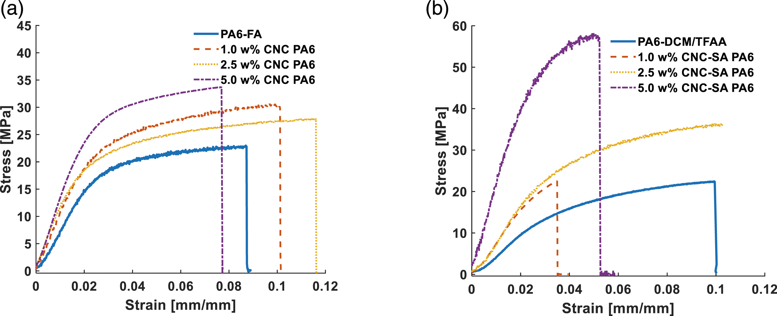
The nanocomposites’ mechanical properties were investigated via uniaxial tensile testing (Figure 9). Typical stress–strain graphs of the CNC (a) and CNC-SA (b) reinforced PA6 are given in Figure 10. It should be noted that two neat PA6 results are reported because unmodified and modified CNC reinforced films were produced using different solvents due to the aforementioned reasons. The photo of tensile tester. Typical stress-strain graph of CNC (a) and CNC-SA (b) reinforced PA6 samples.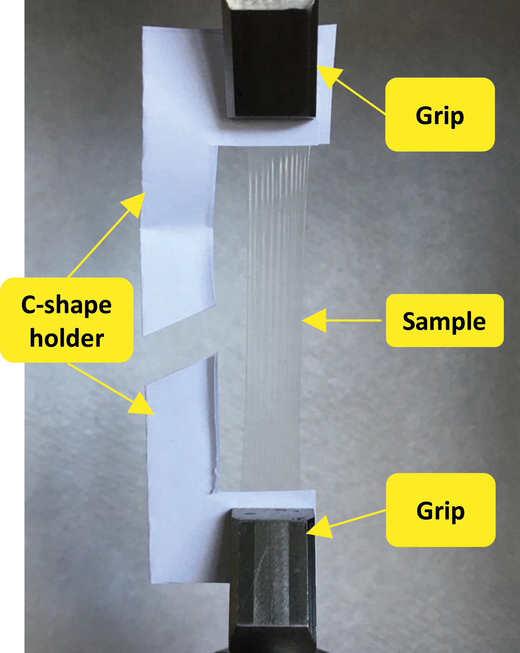
The elastic modulus, tensile strength and elongation-at-break data for CNC (a) and CNC-SA (b) reinforced PA6, respectively, are presented in Figure 11. First, the differences in the elastic modulus of the two types of neat PA6 samples should be discussed when FA (used for CNC) and DCM/TFAA (used for CNC-SA) were used as solvents. As it can be observed, a dramatic decrease of elastic modulus of neat PA6 occurred when dissolved in DCM/TFAA. A study conducted by Zhang et al.
60
reported that TFAA is an effective co-solvent that dissolves PA6 at room temperature. The reaction of TFAA with hydrogen atoms of PA6 in dry DCM lead to the corresponding N-trifluoroacetylated derivatives (PA-TFAA), which may result in dissociation of hydrogen bonds between PA6 chains. Moreover, in another work, Veith et al.
55
suggested the acetylation of the amide groups of PA6 with TFAA is a good alternative method to the use of polar, high temperatures solvents and facilitates dissolution in common solvents. However, in their work, Veith et al. also mentioned that this reaction can destroy the crystallinity of the polyamides, which may result in the decrease of mechanical properties. Effect CNC (a) and CNC-SA (b) on elastic modulus, tensile strength, and elongation at break of PA6.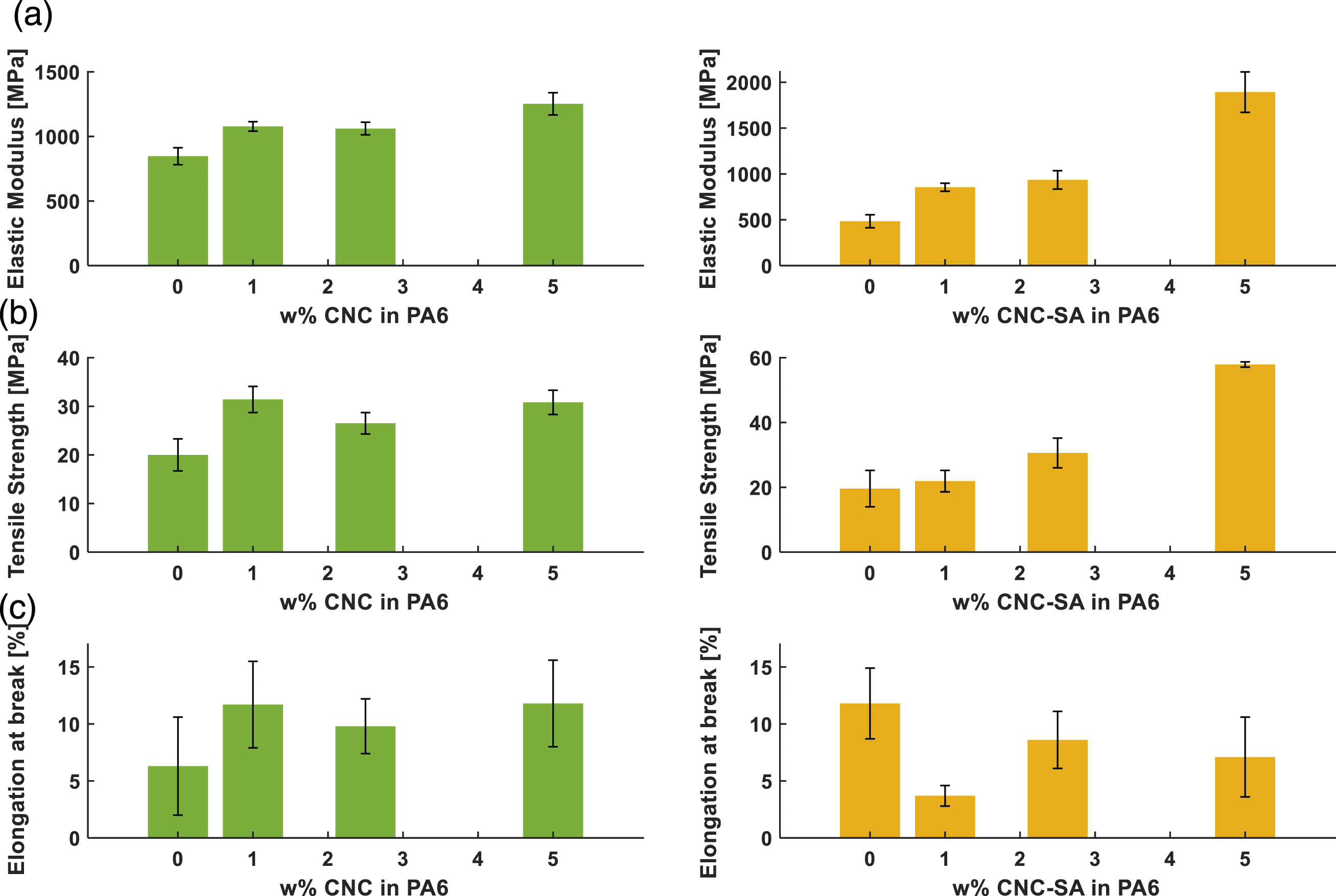
When elastic modulus results of CNC reinforced samples are compared, in general, a slight increase is observed compared to that of neat PA6. The elastic modulus of 5.0 w% CNC reinforced PA6 increased 48%, from 847 MPa to 1252 MPa. When elastic modulus results of CNC-SA reinforced samples are compared with CNC reinforced ones, higher percent increase was observed. The elastic modulus increased 291%—from 484 MPa to 1893 MPa for CNC-SA reinforced PA6.
Tensile strength of PA6 nanocomposites were improved with addition of either, CNC and CNC-SA. For CNC reinforcement, a maximum improvement of 54% was observed at 1.0 w% CNC loading (∼20 MPa to ∼30 MPa). Further increase of the CNC loading did not result in any statistically significant improvement in tensile strength. However, in the case of CNC-SA reinforced PA6, tensile strength is improved by 188% with addition of 5.0 w% CNC-SA. To the best of our knowledge, there is no study showing this remarkable enhancement in mechanical properties for CNC-based polyamide 6 spin-coated films. However, a similar improvements were obtained for electrospun co-polyamide 6,12 reinforced with 1.0 w% CNC. 61
Elastic modulus mainly depends on the properties and w% loading ratio of the constituents of composites, such as reinforcement and matrix volume ratio, direction and shape of the reinforcements. It is of course also crucial to have a homogenous dispersion of reinforcement within the matrix. The interaction at the interface between the CNC and PA6 plays an important role and will influence mechanical behavior of the composite.
62
Promising results were observed in this work, particularly for the 5.0 w% loading case. The change of the surface chemistry of CNC might lead to higher interactions at the interface and increase load transfer from the matrix to CNC, which might result in an increase in mechanical properties. Furthermore, tensile strength and elastic modulus are expected to increase with lower chain mobility. It can be claimed that the grafting of long aliphatic chains might result in a decrease of mobility of PA6 chains and again result in higher mechanical properties. The results presented here suggest that DCM/TFAA lowered the mechanical properties of neat PA6. As previously mentioned, hydrogen bonds between PA6 chains might be broken and this might give a chance to CNC-SA for better distribution, which would increase the mechanical properties of the composite. Figure 12 shows schematics of reaction of PA6 with TFAA and its effect on the CNC-SA reinforced PA6. Schematics of the N-trifluoroacetylation reaction of PA6 with TFAA.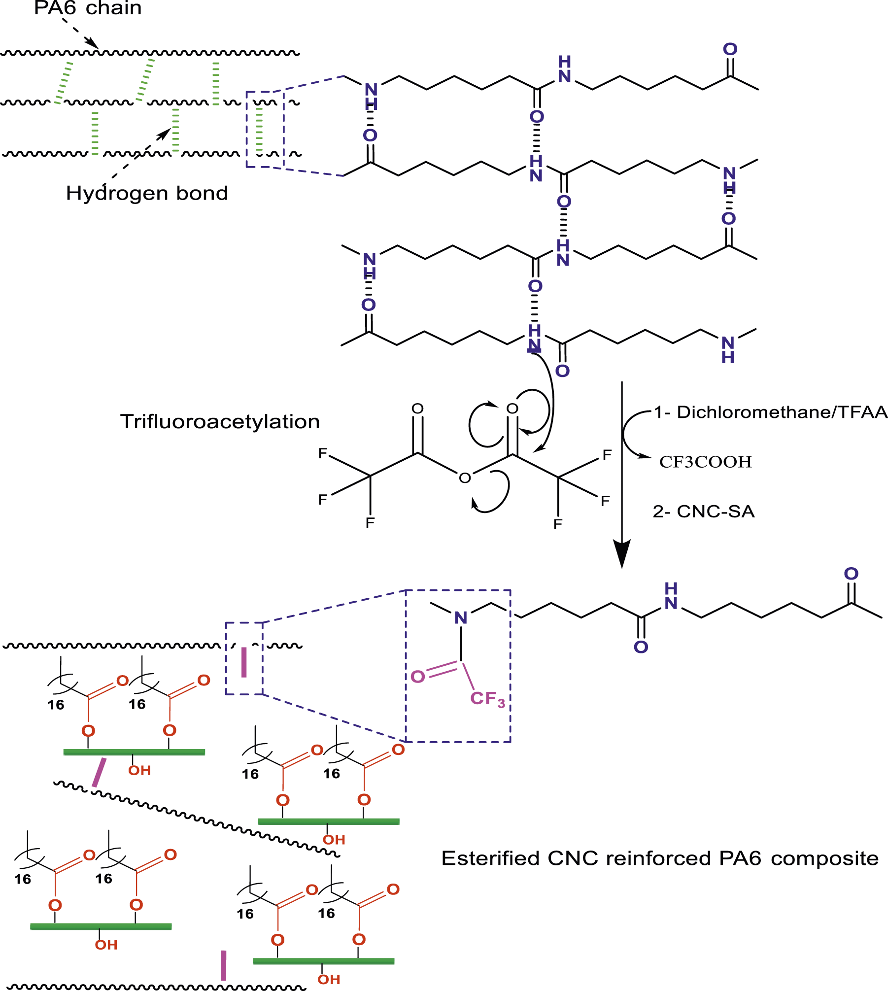
Elongation-at-break was expected to decrease with the addition of CNC and CNC-SA since they are more crystalline and brittle than PA6. Moreover, elongation-at-break can easily be lowered due to agglomeration, stress concentration or defects in the material. Although elongation at break is sensitive to many variables, it did not show a significant decrease for CNC PA6 composites when CNC concentration was increased. On the other hand, we observed that it was lowered as CNC-SA concentration was increased.
It should be noted that the obtained mechanical results of neat PA6 in this study are low compared to some studies that reported high mechanical findings of PA6 produced with thermal based processes. 23 This is probably due to several factors: (i) the impact of solvents used, (ii) the source of PA6 (commercial versus industrial grades), and (iii) the process parameters were not optimized. In fact, our group is currently investigating the effects of operational parameters, including cellulose nanocrystals loading, type of solvent, solid (polyamide 6 and CNC) to solvent ratio, sonication time, and spinning rate on the mechanical properties of the films. Another major factor affecting the mechanical properties is the effect of heat on crystal structure. Based on our work in progress, we observed α and γ phases in spin coated samples and only γ-phase in injection molded samples. Each phase has different crystal structure and this may lead to different mechanical properties.
Conclusion
In this study, we evaluated the effect of CNC and CNC-SA as reinforcing agents in a PA6 matrix on the nanocomposites’ mechanical properties. CNC was modified with a covalent coupling agent (CNC-SA) to increase the dispersion of the CNC within the solvent and eventually within the polymeric matrix. Modification of CNC was proven with advanced characterization tools such as XPS, FTIR, and TEM. After that, CNC and CNC-SA was dissolved in solvent and mixed with PA6. The mixture was spin-coated to obtain samples. TEM was used to observe CNC and CNC-SA in PA6. Long staining protocol was followed to observe CNC in PA6 matrix. To authors’ knowledge, this is the first study showing CNC in PA6 under TEM. Thermal analysis showed that solvent usage decreased the crystallinity of PA6 compared to unprocessed PA6; however, CNC and CNC-SA addition increased mechanical properties of PA6. This effect became significant, particularly for the 5.0 w% CNC loaded nanocomposites—where 48% and 291% increase in elastic modulus of CNC and CNC-SA reinforced PA6, respectively. Similarly, the tensile strength was improved by 54% and 188% with addition of CNC and CNC-SA, respectively.
Although solvent-based processes are difficult to apply for existing industrial applications, it offers possible high-tech applications that may require uniform thin polymeric materials. Besides, this study showed the potential of CNC as a reinforcement candidate for hydrophobic polymers and PA6 with necessary modifications.
Footnotes
Acknowledgments
The authors gratefully acknowledge the Alberta Innovates and Alberta-Ontario Innovation Program through Alberta Innovates, FPInnovations (SFR02735 Nanocellulose Challenges) and Natural Science and Engineering Research Council of Canada (NSERC) Collaborative Research and Development Grants (CRDPJ 500602-16) for financial support. Discussions with Dr. Wadood Hamad, FPInnovations, on CNC functionalization and composite processing are kindly acknowledged.
Declaration of conflicting interests
The author(s) declared no potential conflicts of interest with respect to the research, authorship, and/or publication of this article.
Funding
The author(s) received no financial support for the research, authorship, and/or publication of this article.