
Abstract
In this article, tailored temperature zones are used to obtain improved quality during rapid, high pressure forming of multi-stacked unidirectional prepreg. Particularly in aerospace applications, commonly used forming processes for multi-stacked unidirectional prepreg are often considered a bottleneck in production since the forming cycle requires both heating and cooling ramps and consequently takes long time—often about 1 h. It is possible to speed up the process by using elevated pressure and temperature. However, higher pressure and temperature also increase the influence of pressure gradient-driven, in-plane material movement (squeeze flow). This typically appears as radius thinning when forming a C-spar geometry on a male mold. Decrease of lay-up temperature will decrease radius thinning, but due to obstructed interply slippage, instead bending-induced wrinkles appear on the spar flange. In this article, tailored temperatures at the radius and in the flange area are introduced by using a hot lay-up and a cold mold. The results show that temperature differences of 6℃–10℃ between the radius area and the flange edge of the lay-up decreases radius thinning while still avoiding bending-induced wrinkles. Except from the radius temperature also the stacking sequence and the choice of prepreg system showed a significant influence on the radius thinning.
Keywords
Introduction
Automated tape lay-up of unidirectional (UD) prepreg combined with forming offers a cost-competitive manufacturing method for composite aircraft components. 1 However, forming operations currently used are often considered a bottleneck in production since the forming cycle (including heating and cooling ramps) typically takes around 1 h. 2 Hallander et al. 3 showed that fast forming of multi-stacked UD prepreg could be performed using a high-pressure method (in this case fluid cell press forming). However, when using high forming pressures in the span of 100–400 bars, in-plane material movement occurred due to the pressure gradient developed (squeeze flow), which consequently influenced the forming result. Yanagimoto and Ikeuchi 4 presented a technique for hydraulic press forming where multi-stacked prepreg was sandwiched between two mild steel sheets. Hallander et al. 3 showed that this technique was used when forming a double curved spar in the fluid cell press at 400 bars pressure. The study showed that the squeeze flow effects were effectively reduced on the spar web and flanges when using the steel sheet sandwich technique. However, radius thinning remained.
Radius thinning locally changes the bending stiffness of the lamina and, since it moves entire layers, it affects the stress state in the laminate so the material no longer fulfils design criteria. Geometrical changes due to material movement connected to the thinning could also present an issue later on in the manufacturing process. 5 Sjölander 6 performed a study on radius thinning of multi-stacked UD prepreg in a hot drape forming (HDF) process. The test geometry by Sjölander 6 was a C-spar section formed on a male mold. Radius thinning was primarily found to depend on the squeeze flow of the prepreg layer in the fiber direction perpendicular to the forming direction, depending on the pressure gradient in the spar radius. The pressure gradient was dependent on forming force appearing in the radius when tensioning the forming rubber over the radius. The pressure gradient also depended on the difference between inner and outer radius periphery when forming on a male mold. Corner thickness variations during the cure cycle were also described by Brillant and Hubert 7 and Levy and Hubert. 8 Hallander et al.'s 3 study was also performed on the forming of a multi-stacked prepreg C-spar section at room temperature (R.T.) and at −18℃. Radius thinning was found to decrease with decreasing temperature. The forming of the radius area performed well at both temperatures. However, the wrinkles in the inner plies of the flanges below the radii increased with decreasing temperature. Pandey and Sun 9 and Sun et al. 10 have earlier shown that viscosity is crucial to flange forming. The flange wrinkles were considered to be bending related since they began in the inner plies (tool side) and the outer plies appeared to be in tension. 3 Bending induced flange wrinkles related to the forming temperature has also been described by Bian et al., 11 Farnand et al., 12 and Kappel and Albrecht. 13
Belnoue et al. performed a study on consolidation of a ramped, multi-stacked prepreg lay-up using two stiff mold halves. 14 Pressure gradients appeared due to miss-match between the prepreg lay-up and the mold. This resulted in squeeze flow behavior and out-of-plane wrinkling, which further strengthened the description of squeeze flow behavior observed by Hallander et al. 3 Nixon-Pearson et al. 15 also observed that co-stacked layers (two or more consecutive plies of the same ply direction) were more prone to squeeze flow than non-co-stacked plies when consolidating flat lay-ups with different degrees of co-stacking. This was also observed when comparing radius thinning for co-stacked and non-co-stacked C-spar samples. 3
The pressure build-up in the fluid cell press process (see Figure 1) begins immediately when the forming media comes into contact with a forming material supported by the tool. This will affect consolidation during the forming cycle.
3
In the case of a male spar tool, the pressure built-up will start first in the web area followed by the corner and finally at the flange area. After the forming media has reached the bottom area of the flange, both the forming and the consolidation could be considered to be finished in a fraction of a second.
Principal of fluid cell press forming.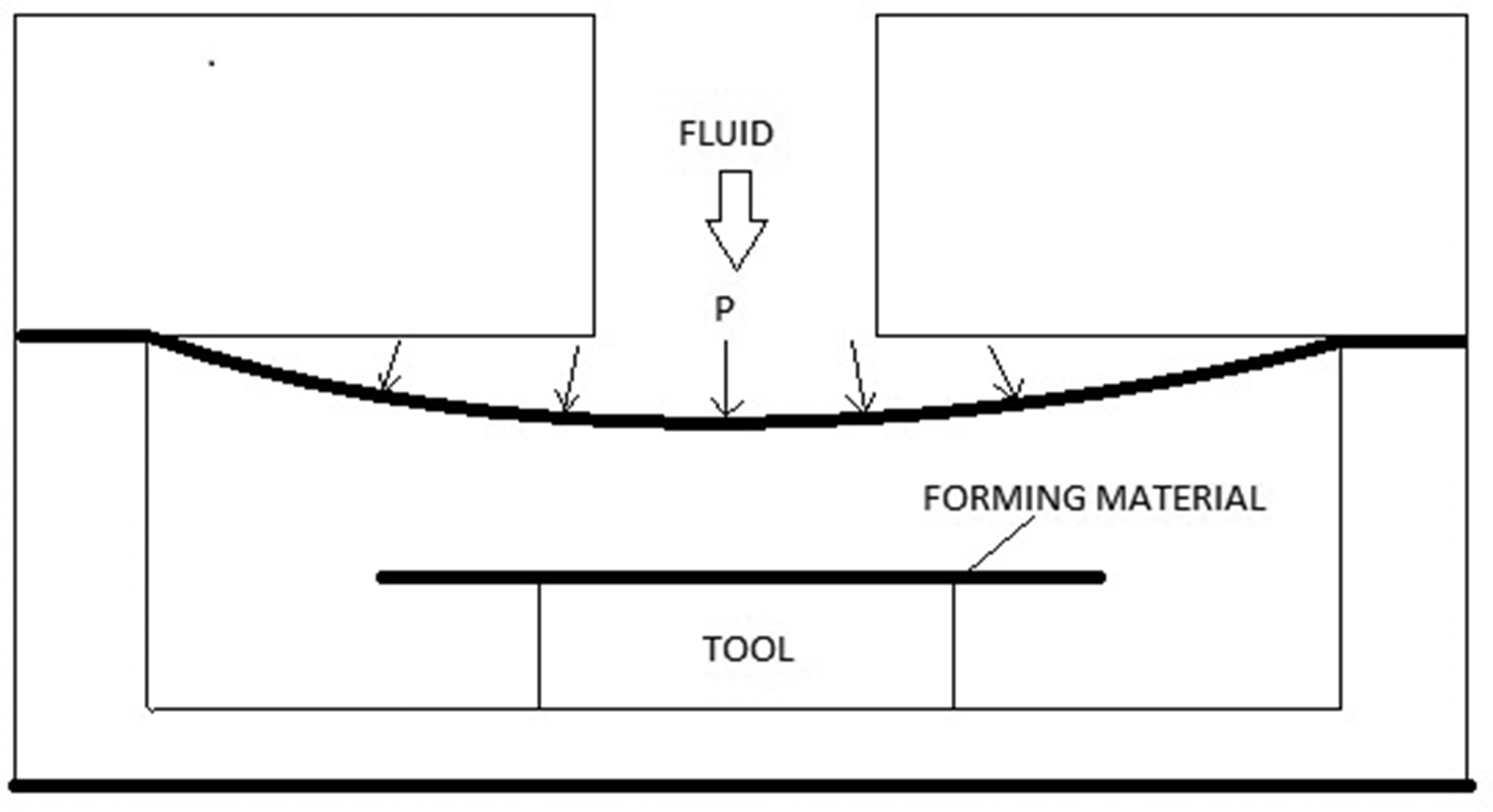
The contradictory requirements favoring the use of a low temperature to avoid radius thinning but an elevated temperature in the spar flange to avoid bending-induced wrinkling became clear in the previous study by Hallander et al. 3 However, to the authors' knowledge no attempt has so far been made to use in-plane, tailored temperature variations during multi-stack forming. The aim of this paper is therefore to study the effect of tailored temperature variations in combination with a high-pressure forming process. An experimental study was performed on multi-stack prepreg forming in a fluid cell press, using tailored temperatures in terms of a hot lay-up and a cold mold as the main process parameter. The tailored forming temperature was combined with a second process parameter. The combinations were either changing lay-up or using an alternative prepreg material.
Methods
This paper presents an experimental study on how tailored temperature variations can be used to avoid radius thinning and bending-induced wrinkling during the high-pressure forming of a multi-stacked thermoset prepreg into a C-spar (see Figure 2). A Quintus Flexform fluid cell press (QP) as shown in Figure 1 was used in this study. A pre-study was performed first to identify the approximate initial forming temperature necessary to avoid bending-induced wrinkling. The experimental QP set-up did not allow any registration of data from thermocouples during the forming so dummy measurements were therefore performed to represent temperature distribution during forming. The main experimental part of this paper contained both a coupon and a demonstrator study. The scope of the coupon study included influence of lay-up and an alternative prepreg material.
C-shaped coupon geometry.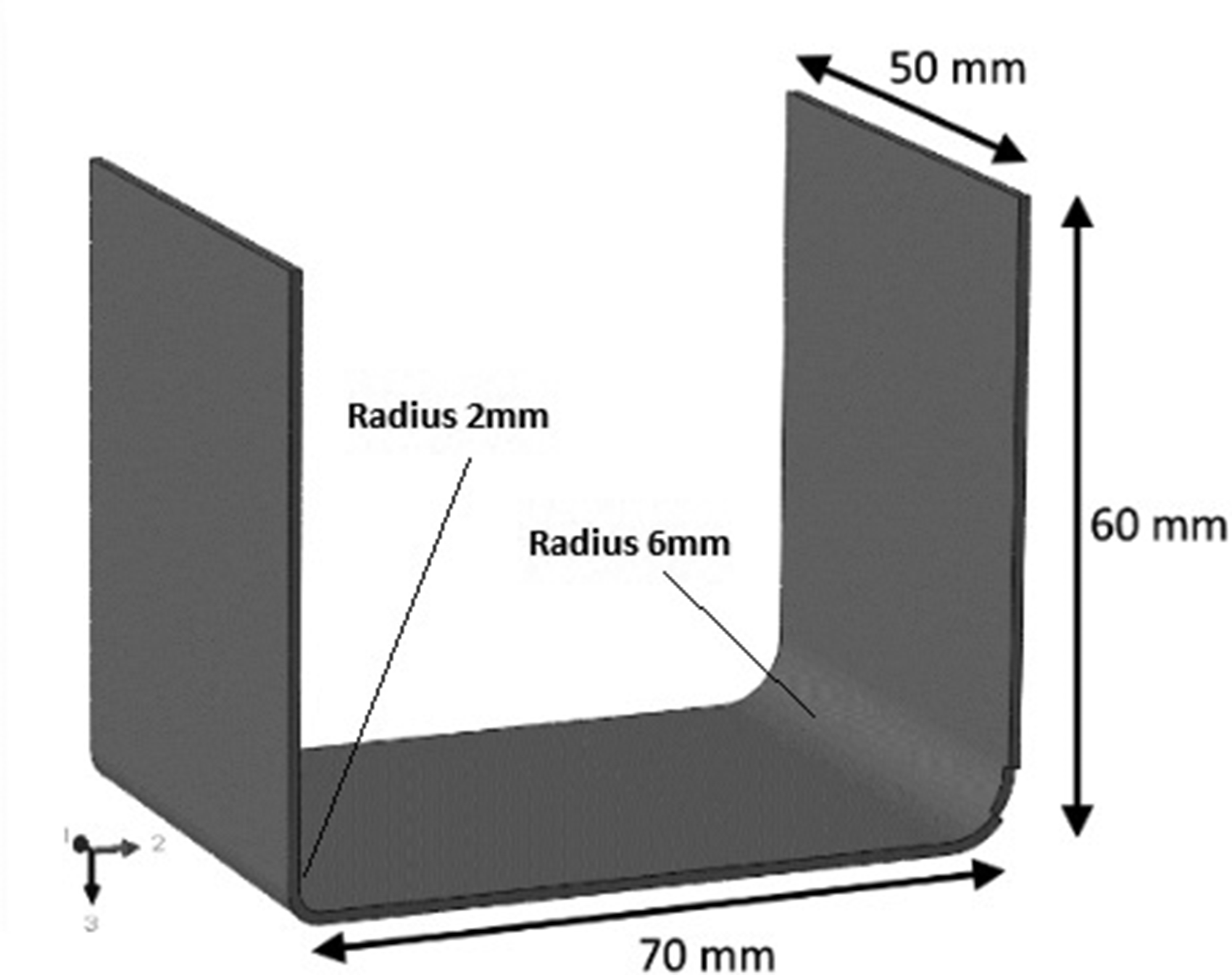
Experimental study
Material
A 180℃ cure epoxy thermoset prepreg (Hexply 6376) with UD high tenacity carbon fiber and ∼57% fiber volume content was used in the major part of the experiments. The prepreg has a cured ply thickness (CPT) of 0.129 mm and did not contain any thermoplastic toughener particles in the matrix. This material is referred to as Prepreg 1.
A second 180℃ cure epoxy thermoset prepreg with UD intermediate modulus carbon fiber containing thermos-plastic toughener particles in the matrix was used in a couple of the C-shaped coupon trials to study the influence of changing material to a prepreg with particles. This material also had ∼57% fiber volume content and a CPT of 0.129 mm. This material is referred to as Prepreg 2. The viscous profile for Prepreg 2 was also similar to Prepreg 1.
Pre-study on isothermal forming of C-shaped coupons
A HDF study of C-shaped coupons (see Figure 2) using isothermal temperatures was performed to map at which temperature bending-induced wrinkles developed in the coupon flange. The HDF method was chosen for the pre-study because of the possibilities of an isothermal forming cycle. The HDF was performed in a box assembly using a silicon rubber diaphragm on top of the assembly, see Figure 3. The constant cross section forming tool had a 70 mm wide web with a 2 mm radius on one side and a 6 mm radius on the other side. Three 180 mm wide and 50 mm long lay-ups were formed at the same time. The lay-up sequence for all HDF samples was [(45, 0, −45, 90)4]s. The pre-study used Prepreg 1. The HDF was performed in an oven and was started when both the forming assembly, tool and lay-up reached the set temperature. Forming was performed at 30℃, 40℃, 45℃, 47.5℃, 50℃, and 60℃.
HDF box assembly for C-shaped coupon forming.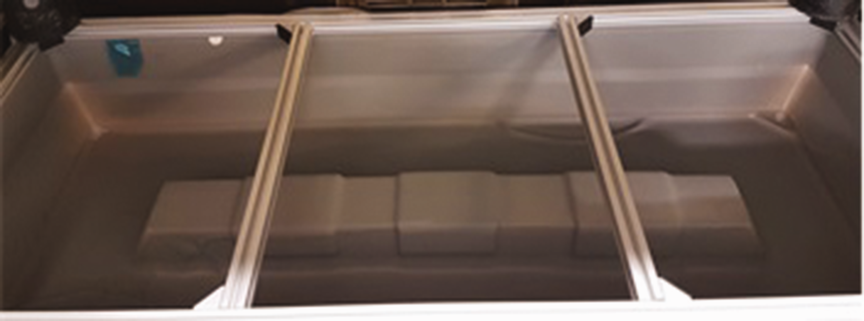
Even if it was difficult to perform an isothermal forming cycle with the QP (see Figure 1). However, with careful planning forming of prepreg was successfully performed in a couple of trials with the same cross section, lay-up, and prepreg as described for the HDF trials. The purpose was to find out more about the critical QP forming temperature and if this temperature was different from the critical HDF forming temperature. The lay-up surface in contact with the QP forming media was covered with a release film and a peel-ply. The lay-up and the consumables described were sandwiched between two mild steel sheets. The steel sheet sandwich including the lay-up was heated in a dedicated oven to an even temperature of 65℃. The steel sheet sandwich was then moved to an aluminum tool block, which had been pre-heated to 35℃ and 40℃, respectively, for the two trials. The forming surface was covered with an 85 shore, 10 mm thick polyurethane (PU) rubber. A thermocouple was placed in the laminate at the flange edge and in the laminate just above the tool radius. These thermocouples was removed before forming. The position of the thermocouples were chosen to control that the condition in the laminate was isothermal. Forming began within 45–60 s after the thermocouple had reached the initial forming temperature of 35℃ and 40℃, respectively, for the two trials. This start delay was caused by the time required for feeding the material into the press and the pressure build-up.
Visual evaluation of out-of-plane wrinkling was performed on the flange tool side since this area was in compression during the forming process. Since the appearance of wrinkles was the only information requested from the study, no curing or further evaluation was performed.
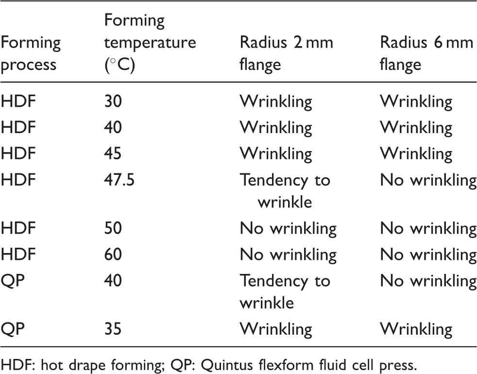
The pre-study stressed the importance of controlling material temperature during forming in order to avoid the appearance of bending-induced wrinkles in the flange, see Figure 4 and Table 1. For the considered material system, the lay-up temperature must be above 47.5℃ to avoid wrinkling and the preferred temperature is assumed to be 50℃ when using Prepreg 1 in the HDF process. For the QP forming process the lay-up temperature must be above 40℃ to avoid wrinkling and the preferred initial forming temperature is assumed to be 45℃ when using the same material as in the HDF trials.
C-shaped coupon at forming temperature: (a) 45℃ (6 mm radius) with wrinkles in the flange, (b) 47.5℃ (6 mm radius), (c) 50℃ (6 mm radius), (d) 45℃ (2 mm radius) with wrinkles in the flange, (e) 47.5℃ (2 mm radius) with tendency of wrinkles in the flange, and (f) 50℃ (2 mm radius). Results of C-shaped coupon forming using isothermal temperatures. HDF: hot drape forming; QP: Quintus flexform fluid cell press.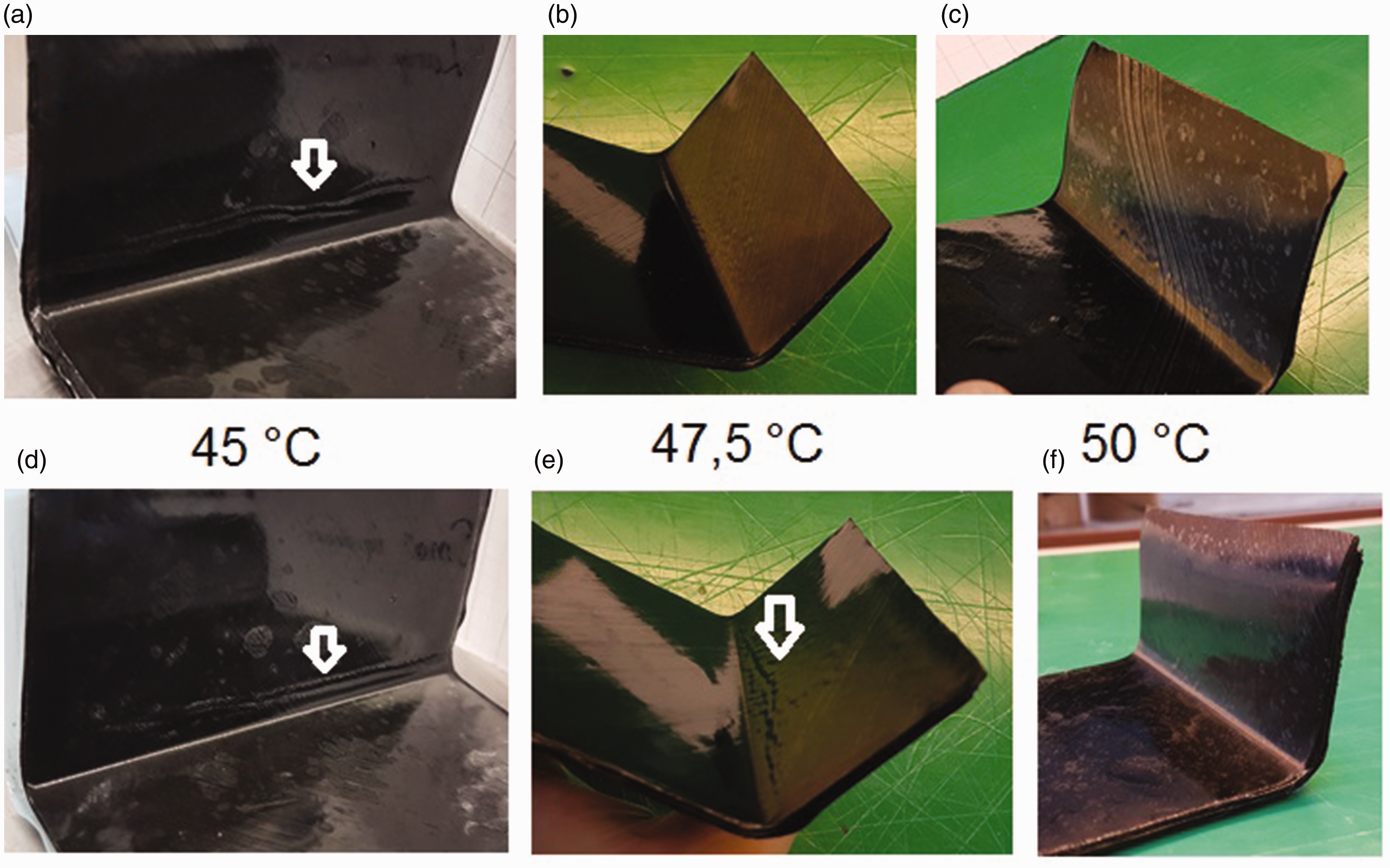
Temperature dummy measurements
Since QP equipment did not allow any registration of data from thermocouples during the forming, dummy measurements were performed capturing the temperature distribution in the laminate at initiation of forming. Prepreg 1 and lay-up [(45, 0, −45, 90)4]s was used in the dummy measurements. Both the C-shaped coupon forming set-up and the double curved demonstrator set-up, described below, were considered in the temperature dummy measurements. The lay-up used in the measurements was prepared using thermocouples in the middle of the stacking sequence to capture temperature at the tool edge (subsequently the C-spar radius area), laminate edge, and tool mid-point in accordance with Figure 5. The same steel sheets, consumables and PU rubber as used in the C-shaped coupon and double curved demonstrator, described below, were used in the temperature dummy measurement set-up.
Dummy temperature measurement set-up with thermocouple positions.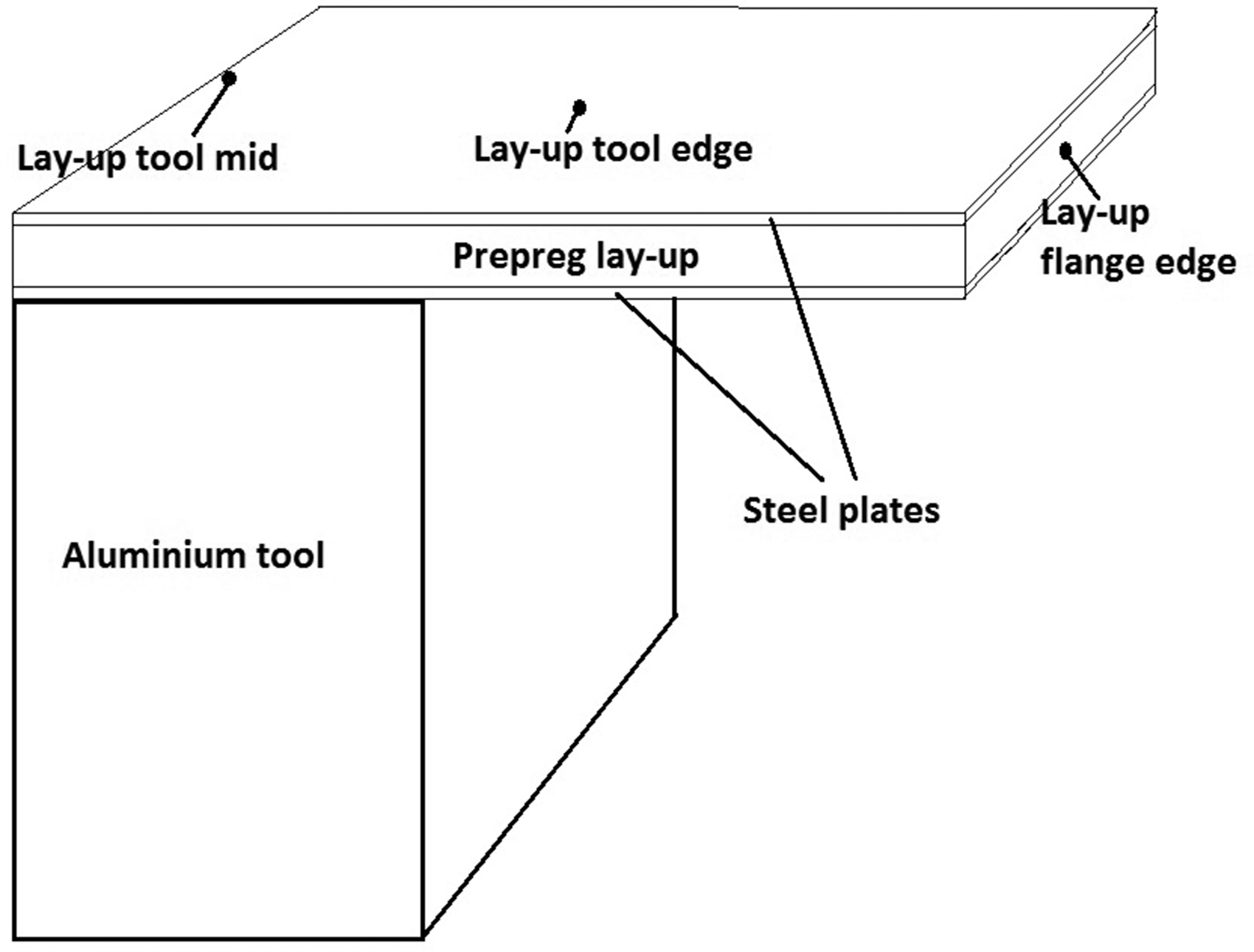
As for the formed samples described below, the sandwiched dummies were heated in an oven to 65℃. After heat-up, the dummies were placed on an aluminum tool block and the measurement started. Thus, measurements to capture material temperatures was performed prior to forming but not after. Since forming in QP is instant, this was considered to give a realistic picture of the actual forming temperature. Measurements capturing coupon-forming tests were performed both at an initial tool temperature of −22℃ and at R.T. The demonstrator dummy measurement was performed on a tool with an initial temperature of −22℃ only.
Forming of C-shaped coupons with tailored temperatures
An experimental study was performed using high-pressure forming in a QP (see Figure 1) to study the influence of different temperatures in the laminate flange area and the laminate web area. The sample geometry was a C-spar section with a 2 mm and a 6 mm radius, see Figure 2. 3 Two different stacking sequences were used in the study, [(45, 0, −45, 90)4]s and [(90, 452, −452, 90, 02)2]s. The second stacking sequence was chosen to study the effect of co-stacking. Two prepreg systems (Prepreg 1 and Prepreg 2) were used in the study to indicate the effects of using different materials.
Test configuration C-shaped coupon forming with tailored temperature variations.
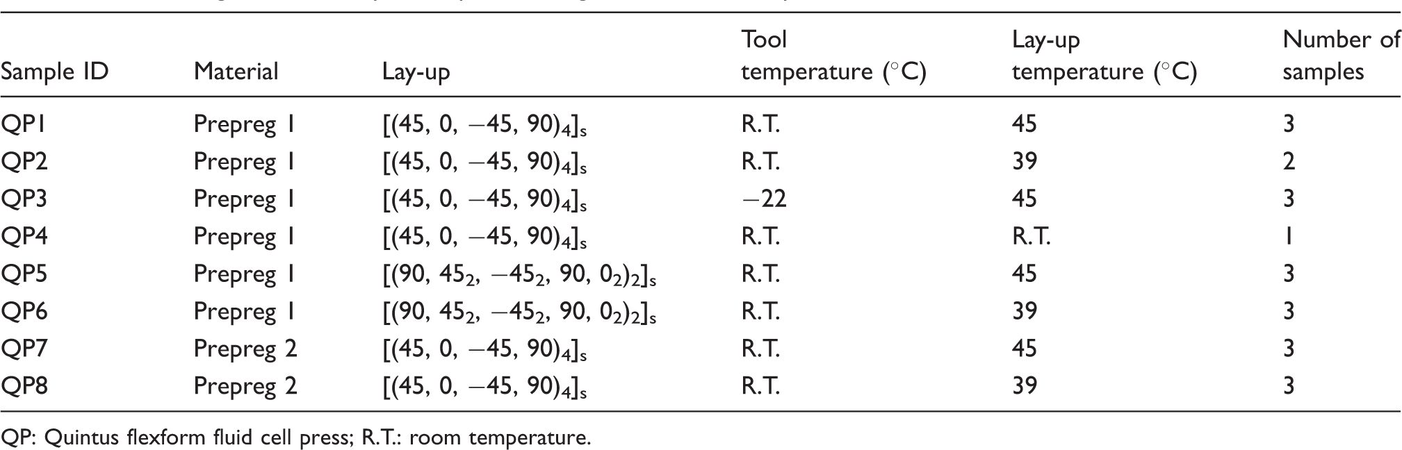
QP: Quintus flexform fluid cell press; R.T.: room temperature.
Forming pressure was set at 400 bars. Based on the results of the pre-study, the upper level of the initial QP forming temperature was set to maximum 45℃. This was made to minimize the radius thinning effect.
All samples were cured using vacuum bag only (VBO) at a curing temperature of 180℃, a heat-up rate of 1.5℃/min and a curing time of 2 h.
The C-shaped coupons were visually inspected after forming and curing. All samples were cut in the middle of the coupon.
Forming of double curved spar using tailored temperature variations
A demonstration on a double curved spar was performed using the tailored forming temperature technique also used in the C-shaped coupon study above. The spar geometry was the same as used by Hallander et al.
3
(see Figure 6). The forming assembly was the same as used in the pre-study above including consumables, steel sheet sandwich, and PU rubber covering. Prepreg 1 was used in the double curved spar study. In order to avoid local out-of-plane wrinkling in the recess area (which could interfere with the study) a [(90, 452, −452, 90, 02)2]s lay-up was used, which previously has been proven not to wrinkle on this geometry.16–18 This lay-up is partly co-stacked which is not favorable for avoiding squeeze flow3,15 in the zero-degree fiber direction in the radius area.
Double-curved spar geometry.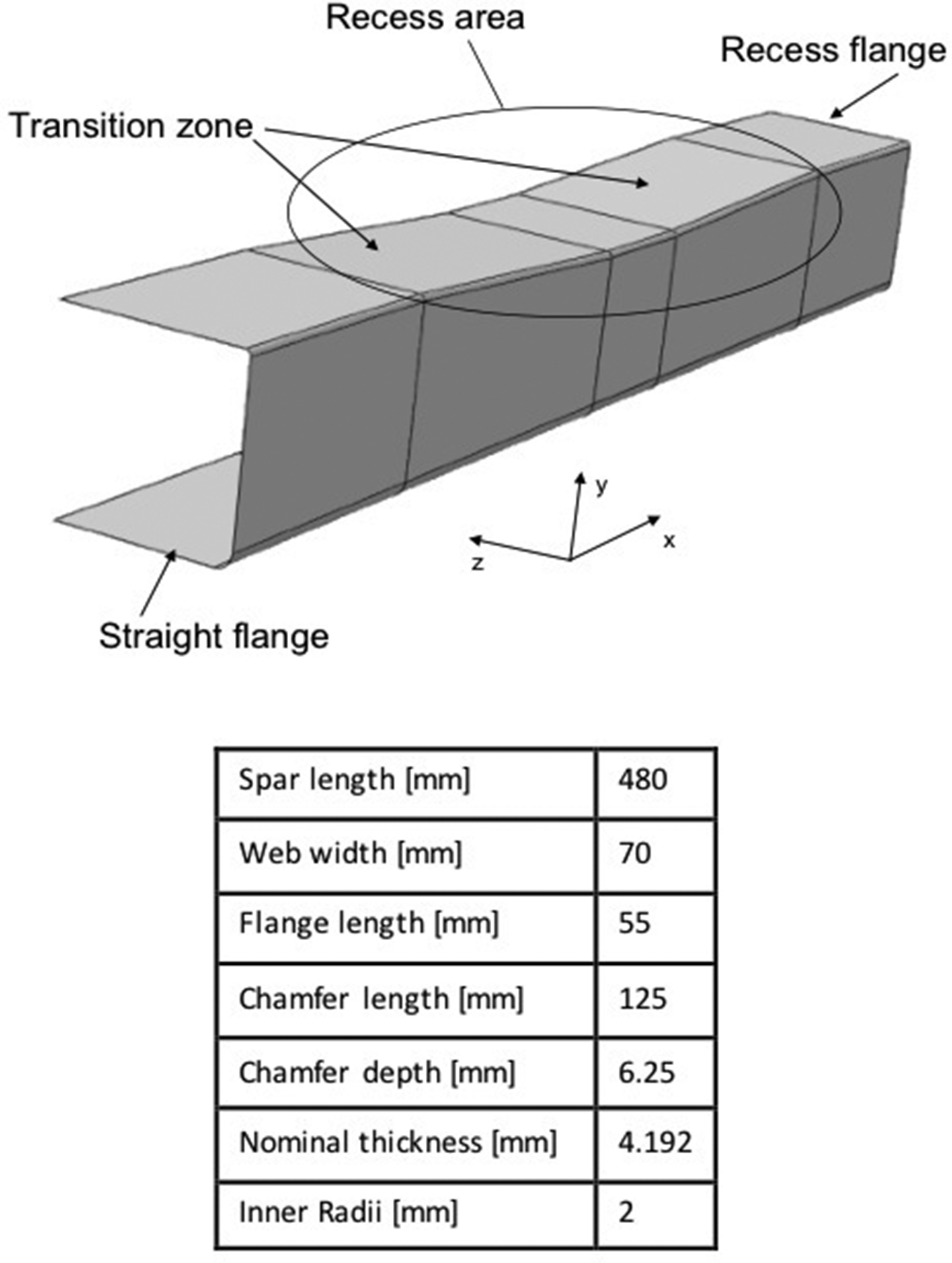
As in the previous study, the steel sheet sandwich including the lay-up was heated in a dedicated oven to an even 65℃. After heat-up the steel sheet sandwich was placed on the cooled (–22℃) aluminum tool block and then the forming surface was covered with PU rubber. A thermocouple was placed in the laminate at the flange edge. Forming began within 45–60 s of the thermocouple reaching 45℃. Forming pressure was set to 400 bars.
The demonstrator was cured in an autoclave applying 7 bars pressure, a curing temperature of 180℃, a heat-up rate of 1.5℃/min and a curing time of 2 h.
The demonstrator was visually inspected after forming and curing. The spar was cut at several positions along the part, parallel to the [90] fiber direction.
Inspection of samples
Cut samples were polished and analyzed using a microscope. The corner thickness was measured in the microscope and the corner thinning was calculated as the deviation between the nominal cured thickness and the measured thickness. The nominal cured thickness for the 32 plies lay-up used in the C-shaped coupon and the double curved spar was calculated to 4.128 mm.
Results
Temperature dummy measurement
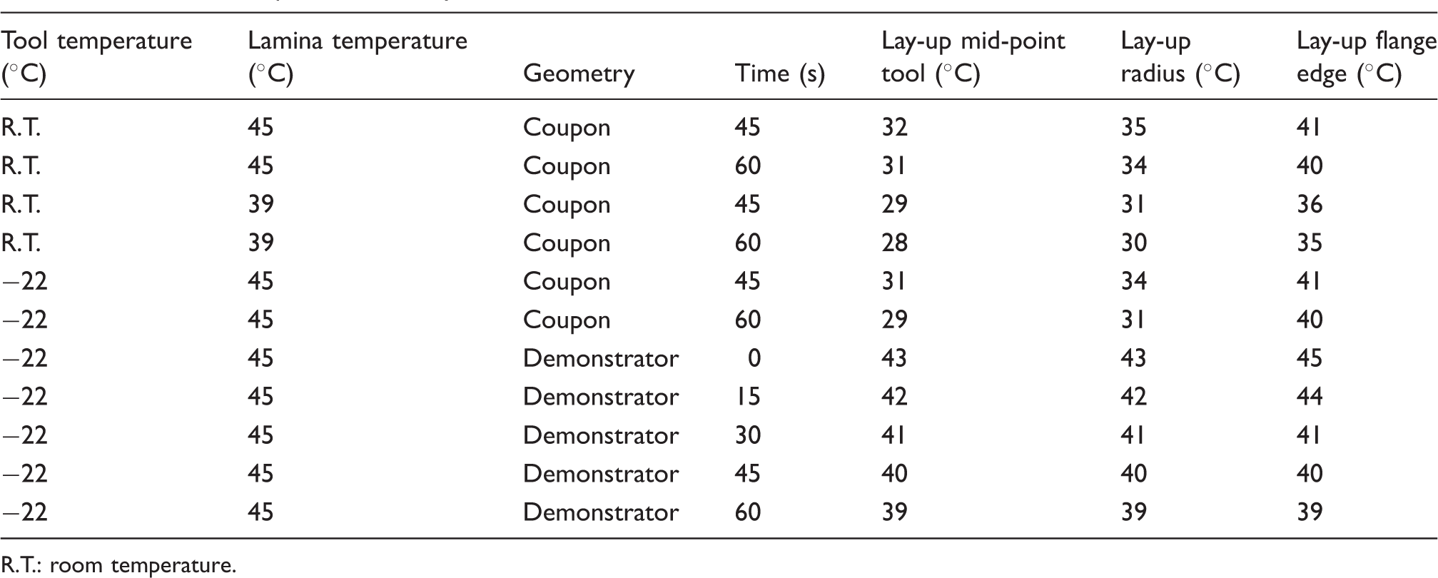
The results of the temperature dummy coupon measurements are presented in Figure 7. A small number of temperature samplings from each dummy coupon in the forming window (time > 45 s) are presented in Table 3 for the lay-up tool mid-point, tool edge and flange edge thermocouples. The demonstrator temperature measurements are presented in Table 3 with a sampling rate of 15 s. The data for the dummy demonstrator showed small temperature differences between the measurement positions. The reasons for this are explained in the discussion chapter.
Temperature of non-formed lamina at different positions relatively the tool. Results of temperature dummy measurement. R.T.: room temperature.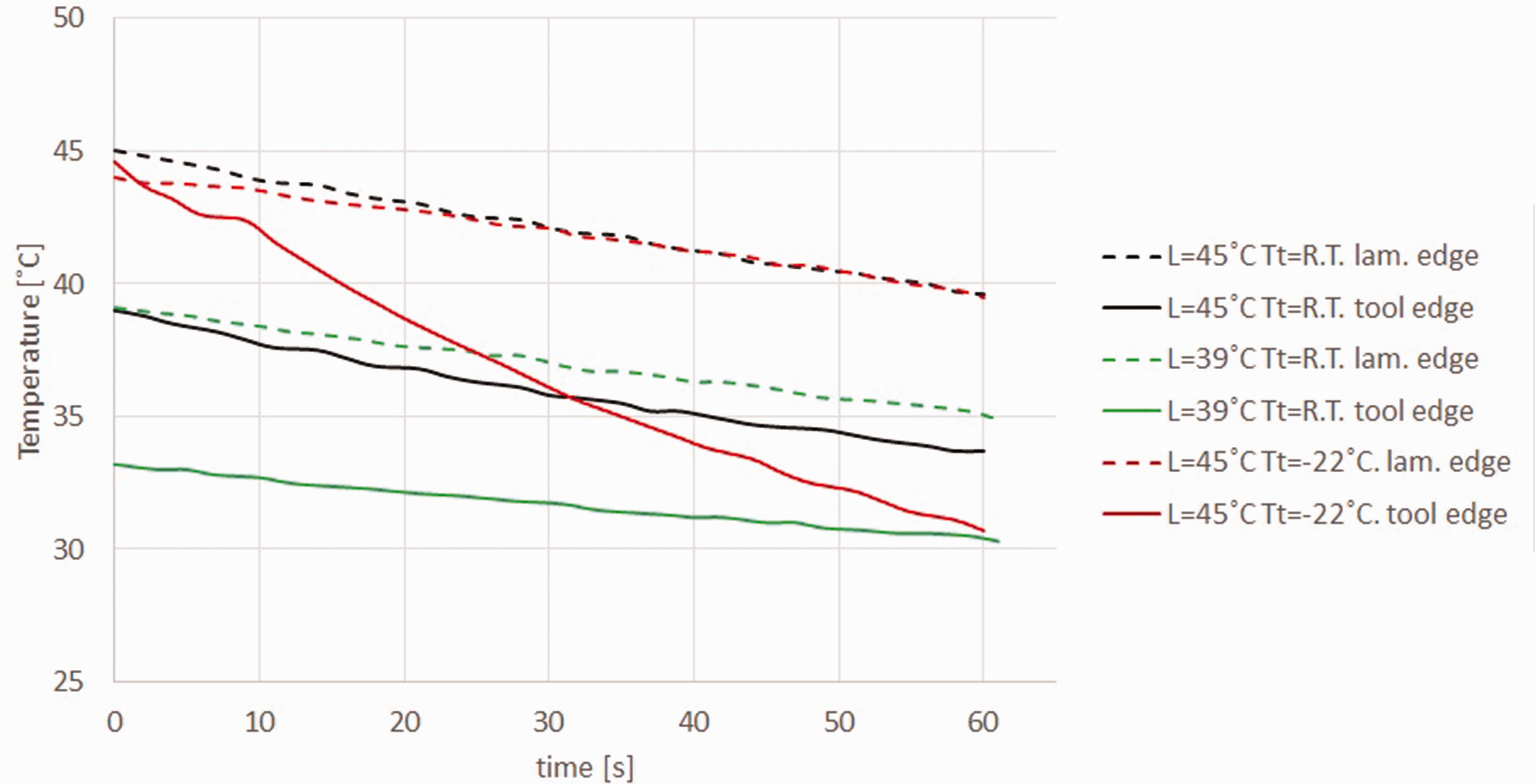
C-shaped coupon-forming study with temperature gradients
Results of C-shaped coupon forming using tailored temperatures.
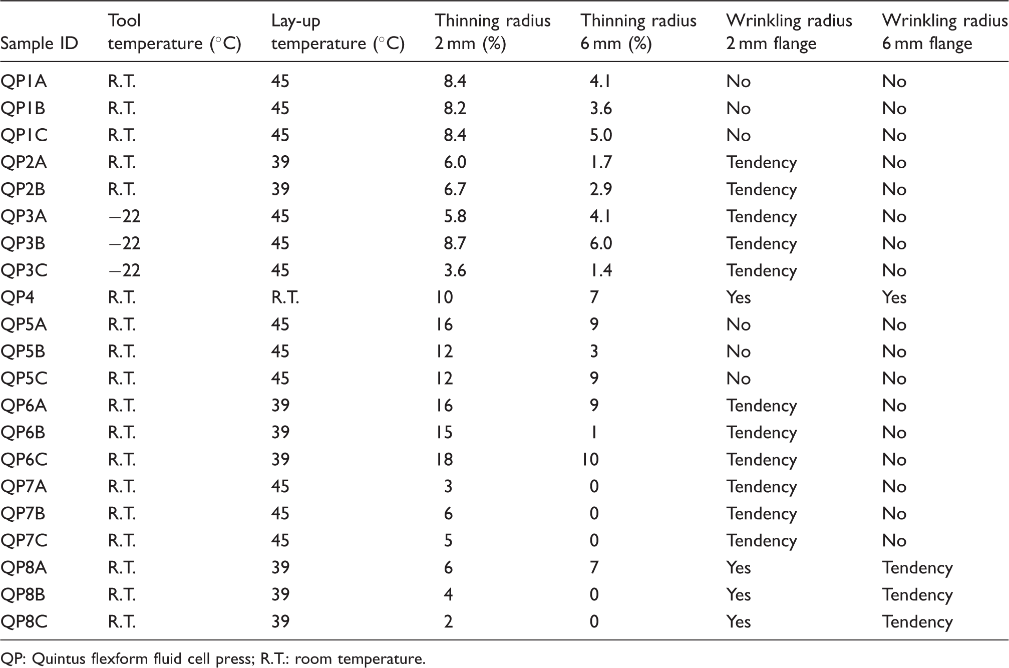
QP: Quintus flexform fluid cell press; R.T.: room temperature.
Double-curved spar
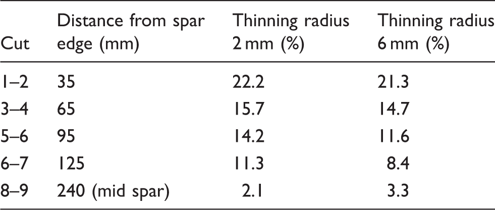
The tailored temperature approach using a 45℃ lay-up and a −22℃ also gave a good performance on the double-curved spar demonstrator. No bending-induced wrinkles in the spar flange appeared and the radius thinning in the 2 mm radii in the middle of the spar was only 2%, see Table 5 and Figure 8. However, the radius thinning increased along the radii from spar mid-point to spar edge. At spar edge, radius thinning was around 20%, which was at the same level as the results from HDF using the same spar geometry and material performed by Hallander et al.
19
Micrograph of spar mid-point cut of double curved spar. Radius thinning on QP-formed double-curved spar.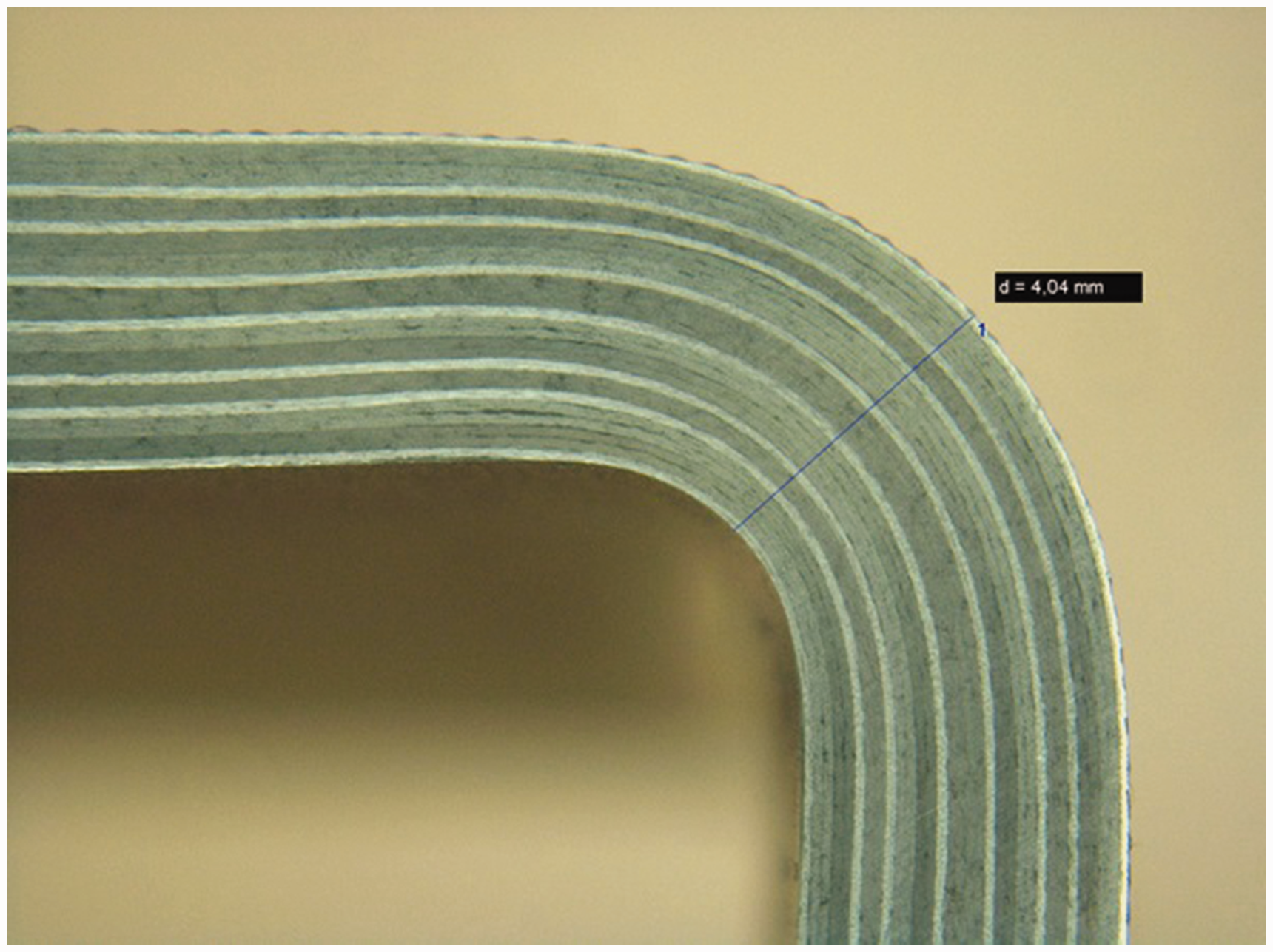
Discussion
The results of the HDF Study of a C-coupon using a multi-stack of Hexply 6376 prepreg (Prepreg 1) shows that an elevated forming temperature of 50℃ was preferable in order to avoid bending-induced wrinkles in the coupon flanges. However, the experimental isothermal pre-study of forming using the same material and lay-up at 400 bars pressure in a QP showed that 45℃ (initial temperature) was high enough to avoid wrinkles in the coupon flanges. This was most probably an effect of the temperature sufficiently reducing interply friction while providing enough forming energy. On the other hand, QP forming at 400 bars and 40℃ showed a tendency for wrinkle development. In this case, the temperature dummy measurement (see Figure 7) showed a temperature of 36℃ at the mid-point of lay-up flange, after 45 s hold.
Forming a quasi-isotropic lay-up ([(45, 0, −45, 90)4]s) at a temperature of 45℃ combined with an tool at R.T. showed a considerable decrease in radius thinning compared to when the same material and lay-up was formed in the same QP set-up with an isothermal temperature of 65℃.
3
Radius thinning in this case decreased from 25% by Hallander et al.
3
and Sjölander,
6
to 8%. When using an initial lay-up temperature of 45℃ and a tool at R.T., the temperature dummy measurements (see Figure 7) showed a temperature of 41℃ at the flange edge and 35℃ at the radii, after 45 s hold. This temperature difference between the flange and radius area appeared to be a good combination for both decreased radius thinning and avoidance of bending-induced wrinkles in the flange. Forming a partly co-stacked lay-up ([(90, 452, −452, 90, 02)2]s) at the same conditions as described above (initial laminate temperature 45℃ and the tool initial at R.T.) showed a radius thinning of 12%–16%, which is an 50%–100% change from the quasi-isotropic lay-up. This was still significantly less radius thinning than the 25% shown by Hallander et al.
3
The thickness change in the co-stacked lay-up was mainly seen in the [0] fiber direction (see Figure 9). This is consistent with observations by Nixon-Pearson et al.
15
described in the introduction chapter, where co-stacked layers showed to be more prone to squeeze flow than non-co-stacked plies. This also strengthens the hypothesis that squeeze flow has a major influence on the radius thinning, which was observed by Hallander et al.
3
and Sjölander.
6
Further, the temperature dummy measurement showed a temperature of 41℃ at the flange edge and 34℃ in radii, after 45 s hold when using an initial lay-up temperature of 45℃ and a tool temperature of −22℃. The experimental results of this set-up (C-coupon trial with a quasi-isotropic lay-up) showed a minor decrease in radius thinning compared to the R.T. tool set-up with the same lay-up temperature. However, a tendency towards bending-induced wrinkles in the flanges also appeared when using the –22℃ tool set-up. The lower limit of the flange temperature when forming using the QP set-up in this study is consequently probably close to 40℃. This is also supported by the isothermal pre-study. The radius thinning in the co-stacked lay-up might however benefit from the lower radius temperature that the −22℃ tool set-up could provide. An indication of this could be seen when comparing the C-shaped coupon trials with the results of the double curved spar demonstrator.
Micrograph of radius 2 mm on C-shaped coupon sample QP5A. The sample was cured using VBO.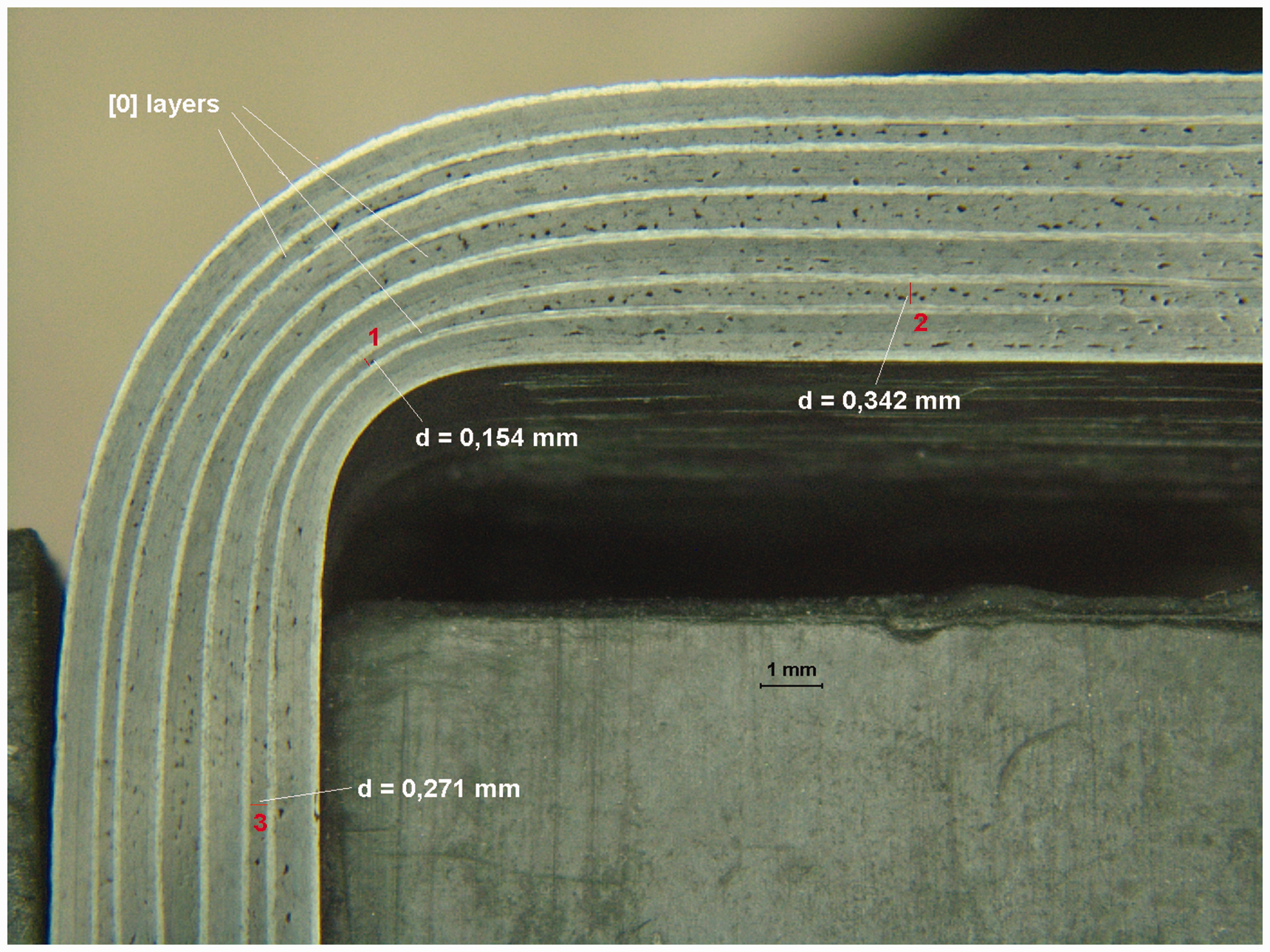
In Figure 10, the recommended process window for the QP forming of the Hexply 6376 prepreg (Prepreg 1) is marked in which the upper right area is the desired temperature window for the flange while the material temperature at the radius should be as low as possible.
Recommended process window for the QP forming based on temperature dummy measurements (Figure 7) and C-coupon forming results.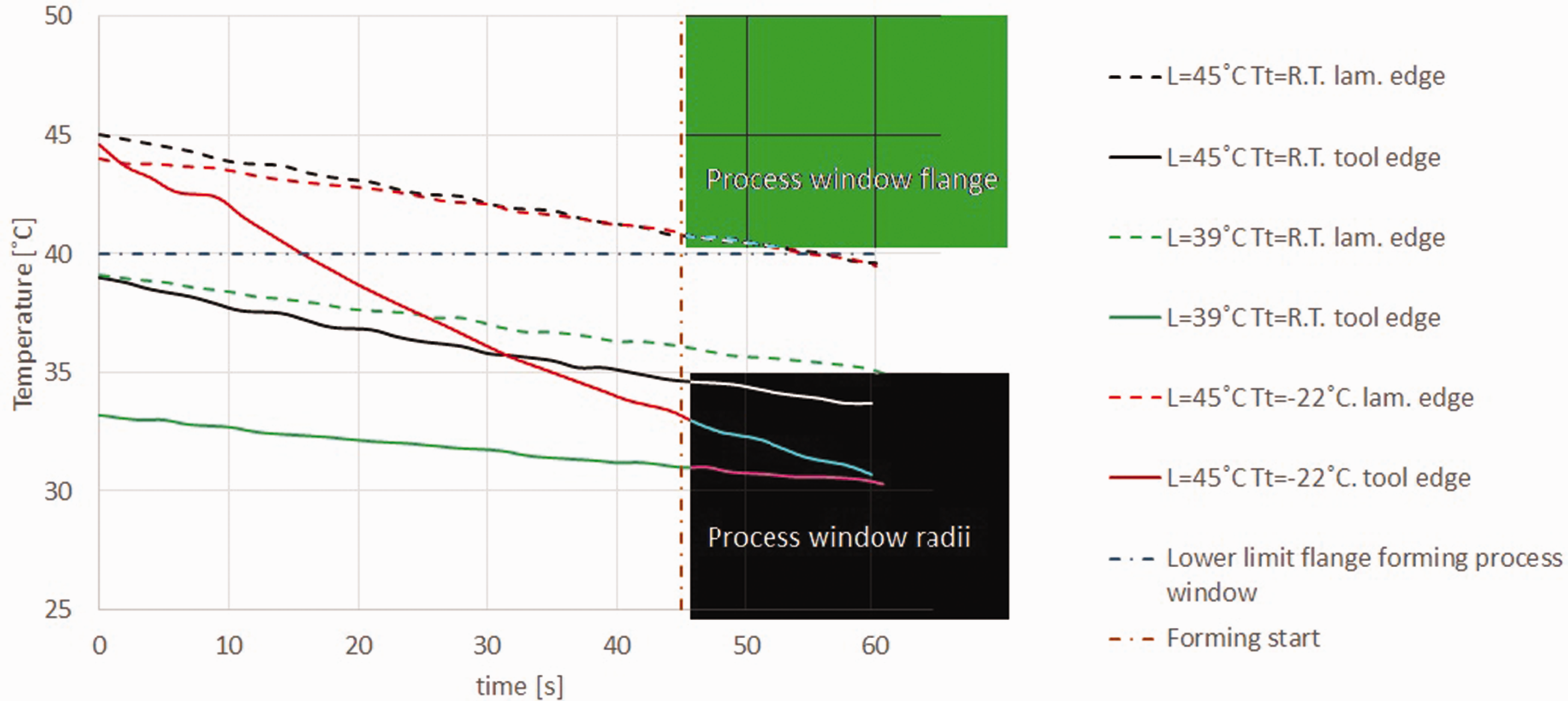
Changing to a prepreg material containing thermo-plastic toughener particles (Prepreg 2) did significantly decrease the level of radius thinning. This was also shown for HDF with the same tool cross-section and materials by Hallander et al. 19 Hallander et al. 19 also shown that the interply friction behavior of a prepreg containing thermo-plastic toughener particles was significantly influenced of the level of compaction. This different friction behavior also seems to have a positive effect on preventing the squeeze flow that most probably causes the radius thinning.
Forming the double-curved demonstrator spar using the partly co-stacked lay-up, Hexply 6376 prepreg (Prepreg 1) and lay-up temperature 45℃ and tool temperature −22℃ showed no tendency towards bending-induced wrinkles in the spar flanges. Since only one demonstrator was manufactured, the lay-up temperature in the spar flanges could potentially still be at the process window limit. A tool temperature of −22℃ would also be more complicated to achieve and control in an industrial manufacturing process.
The forming results of the spar demonstrator showed a very low degree of radius thinning in the spar mid-point of the 2 mm radius. However, the radius thinning appeared to increase along the radius to 20% thinning close to the spar edge. The explanation for this was found when performing the temperature dummy measurements on the demonstrator set-up. It was then observed that the steel sheet sandwich lay-up curved and rose from the mold surface at the lay-up edge and that only the mid-section was in contact with the tool. As a consequence, the temperature dummy measurement showed constant temperatures at the flange edge and tool edge (radii) for the time period 30–60 s. The phenomena observed (sandwich lifting from tool surface at edges) was probably caused by the difference in coefficient of thermal expansion between the prepreg lay-up and the steel sheets. When using QP, the forming media could most probably also cause some edge effects when stretching the forming over the tool edge, which in this case also was close to the laminate edge.
As an outcome of the findings in the current paper experiments in a HDF equipment has been further generated. Due to lack of space the more analytical approach, including modeling and HDF experimental data, will be presented in a future related paper.
Conclusion
Multi-stack forming of aerospace-grade prepreg components is often considered to be a bottleneck in production. The forming process time could be decreased by using elevated parameters in terms of pressure and temperature However, in an earlier study of forming C-spars using high pressures, a contradiction including favorable low temperatures in order to avoid radius thinning and favorable elevated temperature in the spar flange in order to avoid bending-induced wrinkling was observed. In this paper, tailored temperatures at the radius and in the flange area were introduced by using a hot lay-up and a cold mold when forming a C-spar using 400 bars pressure in a QP. The results showed that temperature differences of 6℃–10℃ between the radius area and the flange edge of the lay-up decrease radius thinning while still avoiding bending-induced wrinkles. The desired temperature window for the flange proved to be ≥40℃ while the material temperature at the radius should be as low as possible. Furthermore, the stacking sequence and the choice of prepreg system showed a significant influence on the radius thinning.
Footnotes
Acknowledgements
Special thanks to Mats Hultman for his help with the Quintus press.
Declaration of Conflicting Interests
The author(s) declared no potential conflicts of interest with respect to the research, authorship, and/or publication of this article.
Funding
The author(s) disclosed receipt of the following financial support for the research, authorship, and/or publication of this article: This work is supported by Swedish Foundation for Strategic Research and Saab.