
Abstract
The paper addresses the role played by the cure stage of a vacuum assisted resin transfer molding process in residual stresses generation. The Airstone 780E epoxy resin and Hardener 785H system broadly used in the wind turbine blade industry has been used in this study. The viscous–elastic properties of the resin have been characterized and implemented in a thermo-mechanical FE model. The model has been validated against manufactured [0/90]4 asymmetric laminates. Analysis of residual stresses generation highlighted that compressive stresses generation occurs when the cure is shrinkage dominated and tensile stresses when expansion dominated in the 0° plies. The finding points out that 10% reduction in warpage and 33% reduction in process time can be obtained by selecting cure cycle parameters that allow tensile stresses development during the cure process in the 0° plies.
Introduction
The use of composite materials has been considerably growing over the past four decades. The superior mechanical performances together with the design flexibility offered make them desirable to industries where performance needs to be maximized and weight minimized such as aerospace and wind turbine blades. Nevertheless, the complex phenomena associated with their manufacturing makes a first time right design approach challenging, limiting their potential growth. This is due to the generation of unwanted residual stresses within the part during curing (i.e. cure induced residual stresses). Therefore, the stress state of the soon to be manufactured part needs to be available to the designer.
Cure induced residual stresses arise within the part due to thermal expansion anisotropy, resin shrinkage and tool-part interaction.1–4 The influence of the cure-induced residual stresses on the manufactured part is twofold. On one hand, experimental studies have shown the influence of residual stresses upon mechanical performances of the final part could be beneficial with respect to longitudinal and transverse tensile strength5–7 and delamination properties8,9 and detrimental in the case of in-plane shear strength.9,10 On the other hand, the stress state induced during the cure causes deformation of the part after demolding.11–15 This can be counteracted by designing ad hoc molds accounting for it. 16 However, the practice of building ad hoc molds is task (i.e. material, cure cycle) specific and would require the design of a new mold for each new task, making the process time consuming, inefficient, and not sustainable.
It is therefore of importance to accurately describe the residual stresses formation to predict the stress state of the manufactured parts. This is typically done by characterizing the viscous–elastic material properties of epoxy resins and implementing them in coupled thermo-mechanical finite element (FE) models analysis.1,17–19 Furthermore it has been shown that application of different cure cycles generates different levels of residual stresses1,20–22 and that manufacturer recommended cure cycles (MRCC) do not lead to optimal solutions in terms of residual stresses generation therefore studies on optimal cure cycles to minimize residual stresses have been undertaken.21,23,24 The optimization studies showed that cure cycle tuning is an effective tool to minimize the level of residual stresses. However, the idea of reducing the final residual stress state of the part by introducing cure induced stresses during the manufacturing process counteracting the stresses introduced during cool down has not been addressed yet in literature.
The goal of this study is to understand the generation and development of residual stresses during the cure stage of the vacuum assisted resin transfer molding (VARTM) process, leading to the design of a cure cycle, which reduces residual stresses and process time. To achieve this, the viscous–elastic properties of the resin system used will be characterized and the corresponding material models built and implemented in a coupled thermo-mechanical FE model to accurately predict the cure induced residual stresses throughout the cure process and the final warpage developed. The FE model will be validated against the manufacturing of three asymmetric laminates by means of VARTM process following three different cure cycles. After that, an analysis of the generation and development of residual stresses for the three different laminates will be undertaken. Finally, with the knowledge learnt from the residual stresses development from the three manufactured laminates, a cure cycle will be designed able to reduce final warpage and process time by means of cure-induced residual stresses during manufacturing.
Methodology
The material used in this study is a non-crimp biaxial E-glass fibers fabric by SAERTEX® (X-E-812 g/m2-1270 mm) with 401 g/m2 both in 0° and 90° direction and the two component Airstone™ 780 E epoxy resin and 785 H hardener system utilized for wind turbine blades manufacturing. The resin system possesses excellent flow properties and wettability, with a viscosity at room temperature of 250 mPas and a pot life, to double the initial viscosity, of 180 min. The glass transition temperature of the cured system is 89℃. 25 Section “Thermo-chemical sub-models” reports the constitutive material thermo-chemical sub-models for the composite; section “Thermo-mechanical material models of glass fiber composite” presents the sub-models describing the thermo-mechanical properties of the composite and the characterization methodology used to characterize the thermoset system properties; section “Coupled thermo-mechanical model for residual stresses prediction” describes the coupled thermo-mechanical FE model analysis to predict residual stress generation; section “Validation experiments” reports validation tests results.
Thermo-chemical sub-models
The thermo-chemical material sub-models for the materials adopted in this study have been presented and validated elsewhere.
26
The cure kinetics of the system is as follows

The glass transition temperature of the resin follows the Di Benedetto equation
27

Here,
The specific heat capacity of fiber,


Here, wf represents the weight fiber fraction. The thermal conductivity of the resin depends on degree of cure and temperature and it is expressed as a polynomial function with

With regard to the thermal conductivity of the composite in the longitudinal (

Thermo-mechanical material models of glass fiber composite
To implement the mechanical properties of the composite, contribution from both fibers and resin needs to be accounted for by means of micromechanical relations. The formulation proposed by Chamis
28
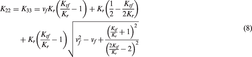
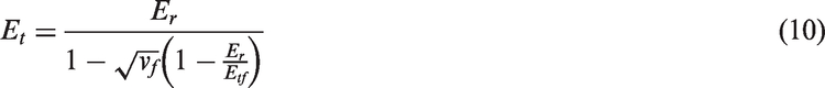
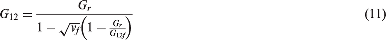
is adopted in this study. The longitudinal modulus of the composite material in the fiber (El), transverse (Et), shear (


To evaluate the evolution of the modulus of the resin (Er) with degree of cure and temperature, different plates of partially cured pure resin samples have been manufactured using an in-house aluminum tool. Four different cycles have been used: (I) 45 min dwell at 70℃, (II) 95 min dwell at 70℃, (III) 255 min dwell at 70℃, and (IV) 135 min dwell at 110℃. Four different degrees of cure have been achieved namely 78%, 85%, 90%, and 98%. The degree of cure of the plates has been predicted by means of cure kinetics and verified via DSC analysis. 26 From the manufactured plates, samples for dynamic mechanical analysis (DMA) have been obtained and tested. The DMA sample size is 50 × 10 × 2.5 mm. Tests have been run with 1 Hz frequency and with a 2℃/min ramp rate. The DMA used is a Perkin Elmer Pyris Diamond DMA, which uses the integrated Perkin Elmer software for data treatment and interpretation. The model to fit the experimental data is described in section “Mechanical and thermo-mechanical resin material properties.”
The longitudinal and transverse coefficients of thermal expansion of the composite can also be formulated by implementing micromechanics laws
29


Thermal mechanical analysis (TMA) tests to evaluate the CTE of the resin (ar) have also been performed. A fully cured sample with dimensions 4 × 3 × 3 mm has been manufactured. The ramp rate utilized during the tests was 2℃/min. Mesogitis et al. 30 considered the CTE constant at glassy and rubbery state; the same assumption has been adopted.


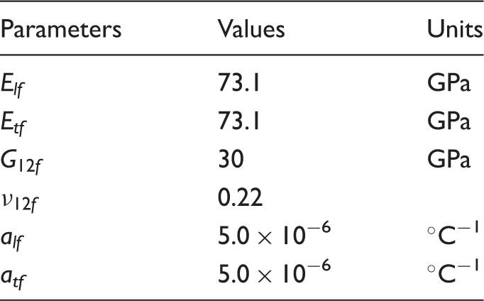
Thermo-mechanical properties of E-glass fibers. 32
Coupled thermo-mechanical model for residual stresses prediction
The coupled thermo-mechanical model implementing chemical, thermal, and mechanical properties previously presented has been built using the commercial FE solver Marc.Mentat®.
33
The FE model is representative of a VARTM process on aluminum tool. In Figure 1, a schematic of the model with the application of boundary conditions is depicted. Three dimensional 8-nodes composite brick elements suitable for coupled thermo-mechanical analysis (Marc® element type 149) were used.
34
The model represents a laminate 900 mm long and 140 mm wide, with a [0/90]4 asymmetric lay-up and 54% fiber volume fraction, which was measured from the manufactured laminates. Thickness is equal to 2.5 mm. Due to in-plane symmetry reasons a quarter of the laminate has been modeled. Furthermore, the application of insulation boundary conditions in y direction reduces the problem to 2D hence an internal strip close to the y symmetry line is modeled. The FE model comprises 3270 nodes and 1736 elements. The initial degree of cure has been calculated using the cure kinetics model and considering the duration of the infusion, preceding the curing cycle and it is equal to 0.08 whilst room temperature initial condition has been applied to all the nodes. Fixed displacement boundary conditions to avoid rigid body movements and symmetry boundary conditions have been also applied. Fixed temperature boundary conditions following the cure profile have been applied to the nodes in contact with the aluminum plate using FORCDT user subroutine whilst at the vacuum bag side a natural air convection boundary condition has been applied using the user subroutine UFILM. The sink temperature follows the cure profile whereas the convection coefficient is equal to 13.7 W/m℃.
35
The thermo-chemical constitutive material sub-models for cure kinetics, specific heat, and thermal conductivity have been implemented using the user subroutines UCURE, USPCHT, and ANKOND, respectively. The material sub-models for mechanical moduli, Poisson’s ratio, and CTE have been implemented using HOOKLW and ANEXP user subroutines.
36
At the end of the curing process, pressure boundary condition at the vacuum bag side is removed and the part can warp.
Schematic of model boundary conditions (a) length thickness, (b) width–thickness, and (c) FE model warpage prediction.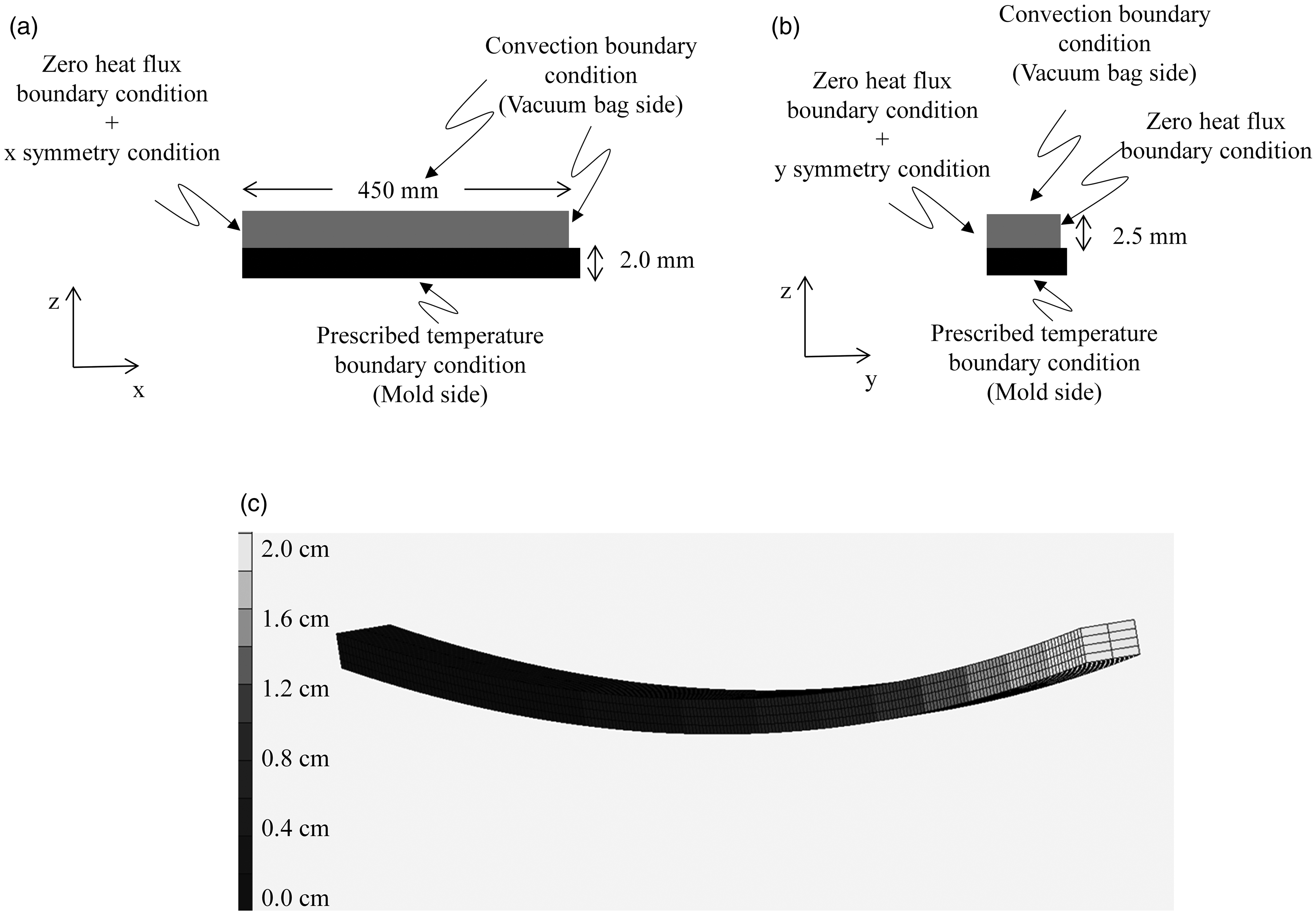
Validation experiments
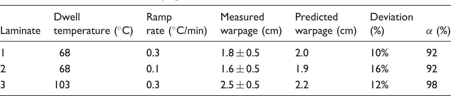
Three laminates were manufactured for model validation purpose. The first cure profile followed the MRCC dictating a 0.33℃/min ramp up to a 70℃ dwell held for 4 h (Laminate 1); the second cure profile prescribed a 0.1℃/min (below this value process time becomes too long) ramp up to a 70℃ dwell kept for 4 h (Laminate 2); the third cure profile adopted a 0.33℃/min ramp up to a 105℃ held for 4 h (Laminate 3). The temperature of 105℃ was chosen, as it constitutes a technological limit for molds normally used by the wind industry. The cure cycles adopted are presented in Figure 2.
Cure cycles used for laminates manufacturing.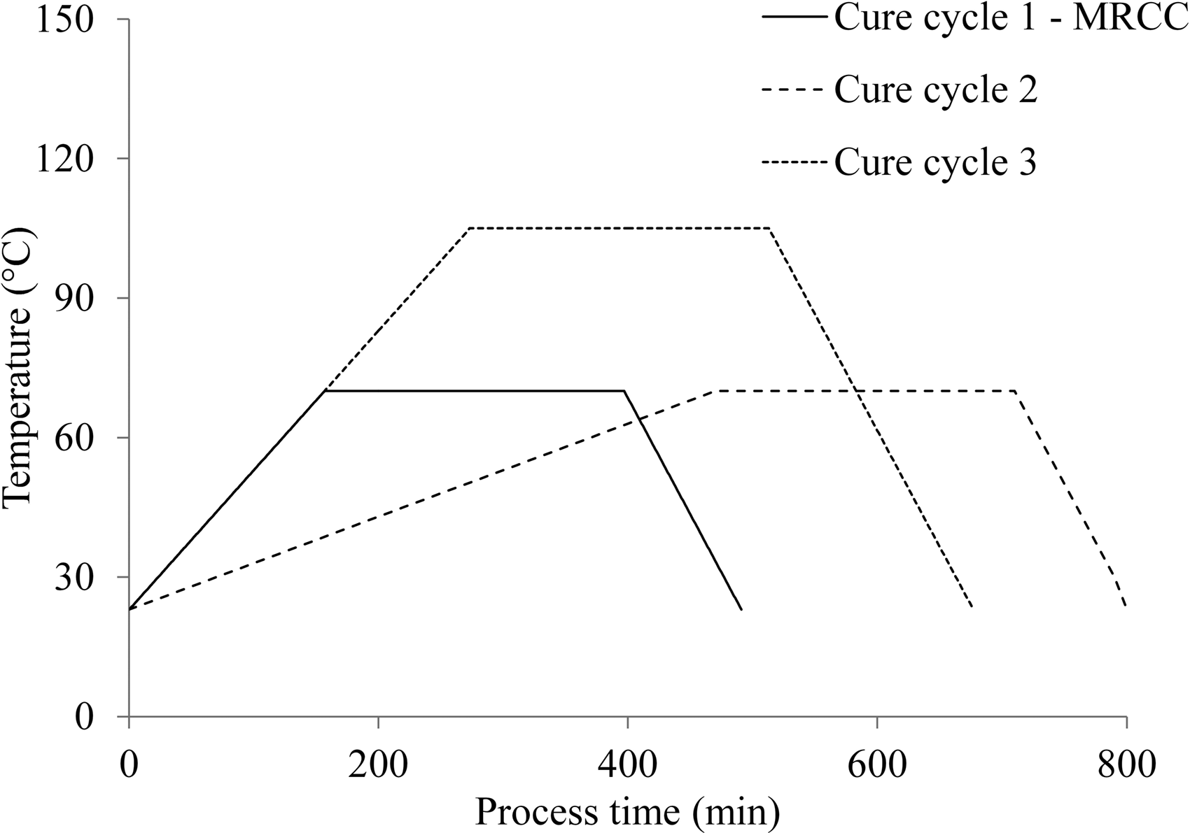
At the end of each dwell, the same 0.5℃/min cool down was applied. Three (3) thermocouples were used to monitor the temperature profile during cure. The thermocouples were positioned (1) between the mold and the bottom ply, (2) on the top ply, and (3) in the oven. The laminate edges of the manufactured part were trimmed to obtain a straight edge to facilitate the measurement. All the laminates were laid on their length side (see Figure 3) for warpage measurements to avoid that part weight affected the measurements. The warpage profile was drawn onto paper. The distance of the profile from a straight line was then measured with a caliper. The error associated to the measurement was assumed to be ±0.5 mm.
37
Experimental warpage for the three manufactured laminates.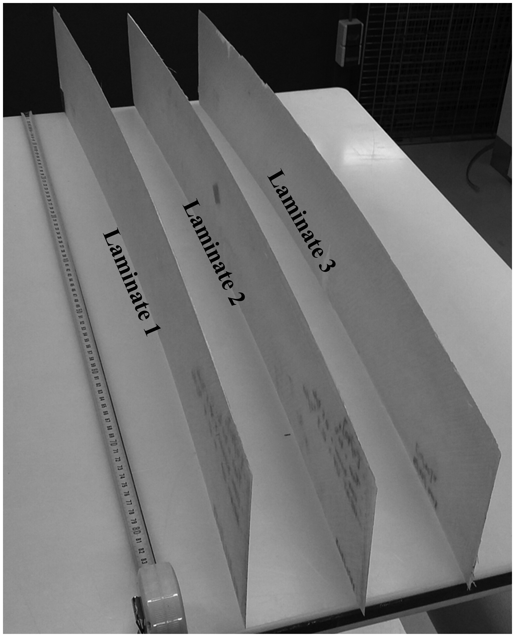
Results and discussion
Firstly, the mechanical and thermo-mechanical characterization of the resin system used with the corresponding development of constitutive material models will be described in section “Mechanical and thermo-mechanical resin material properties.” Secondly, section “Model validation” will present the validation of the FE model built against the manufacturing of three different laminates and section “Residual stresses generation analysis” will analyze the generation and development of residual stresses.
Mechanical and thermo-mechanical resin material properties
Figure 4 shows the results of the DMA tests. The data reported shows a clear dependence of the resin mechanical modulus on temperature before transition when the resin is at the glassy state. The scatter in the initial value of the modulus among the four partially cured samples is due to material variability and therefore, it has been averaged and it rounds up to 4.61 ± 0.14 GPa ( DMA experimental data fitting. Fitting parameters for modulus and CTE constitutive models.
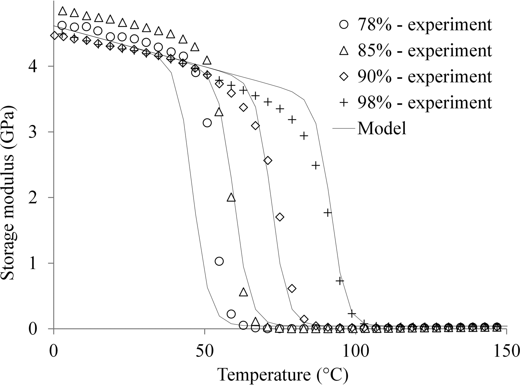
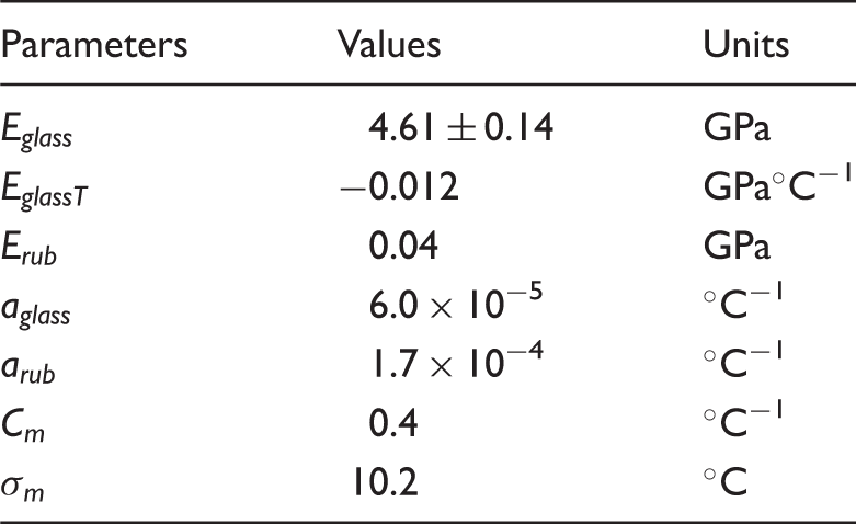
Figure 5 reports the test results of the TMA campaign on the fully cured sample. The value of CTE at glassy and rubbery state has been identified as the slope of the linear regions before and after transition, whilst the values of TMA results for the fully cured sample.
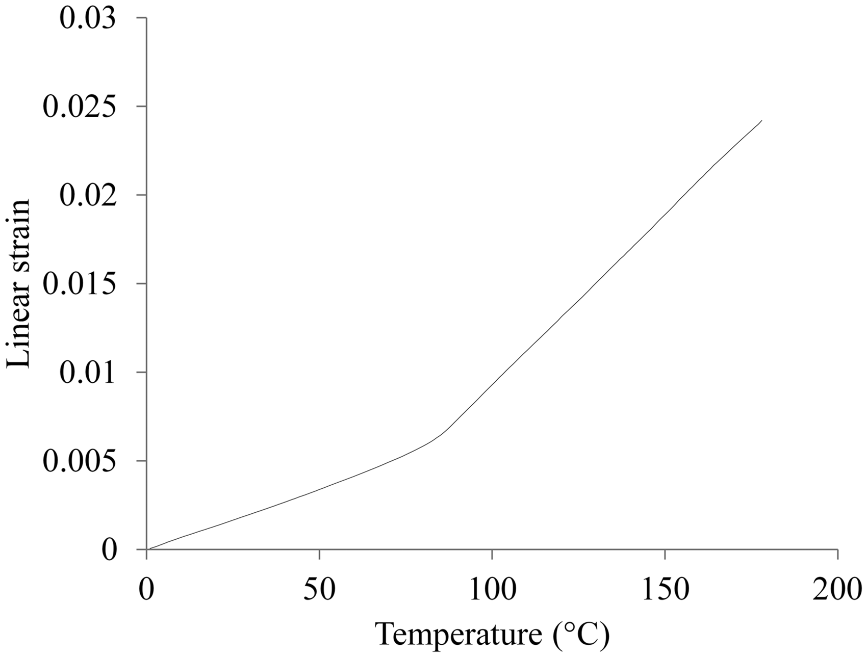
As concerns the Poisson’s ratio model, constant values have been assumed at the glassy and rubbery state whilst the step transition has been modeled following the modulus constitutive material model (i.e. 
The total volumetric shrinkage of the resin is 5.6%, which corresponds to a linear shrinkage of 1.9%. As reported in literature the resin shrinkage can be fitted by either a linear or a bi-linear function.
31
In this case, only two experimental points have been measured therefore a linear dependence on the degree of cure has been adopted. The equation can be written as follows in which 
Model validation
To validate the FE model with viscous–elastic material properties presented in the previous sections, three laminates have been manufactured following three different cure profiles aimed at varying dwell temperature and ramp rate as reported in section “Validation experiments.” The recorded data for Laminate 1 are reported in Figure 6. The temperature observed through thickness is uniform.
Temperature evolution measured by thermocouples during manufacturing of Laminate 1.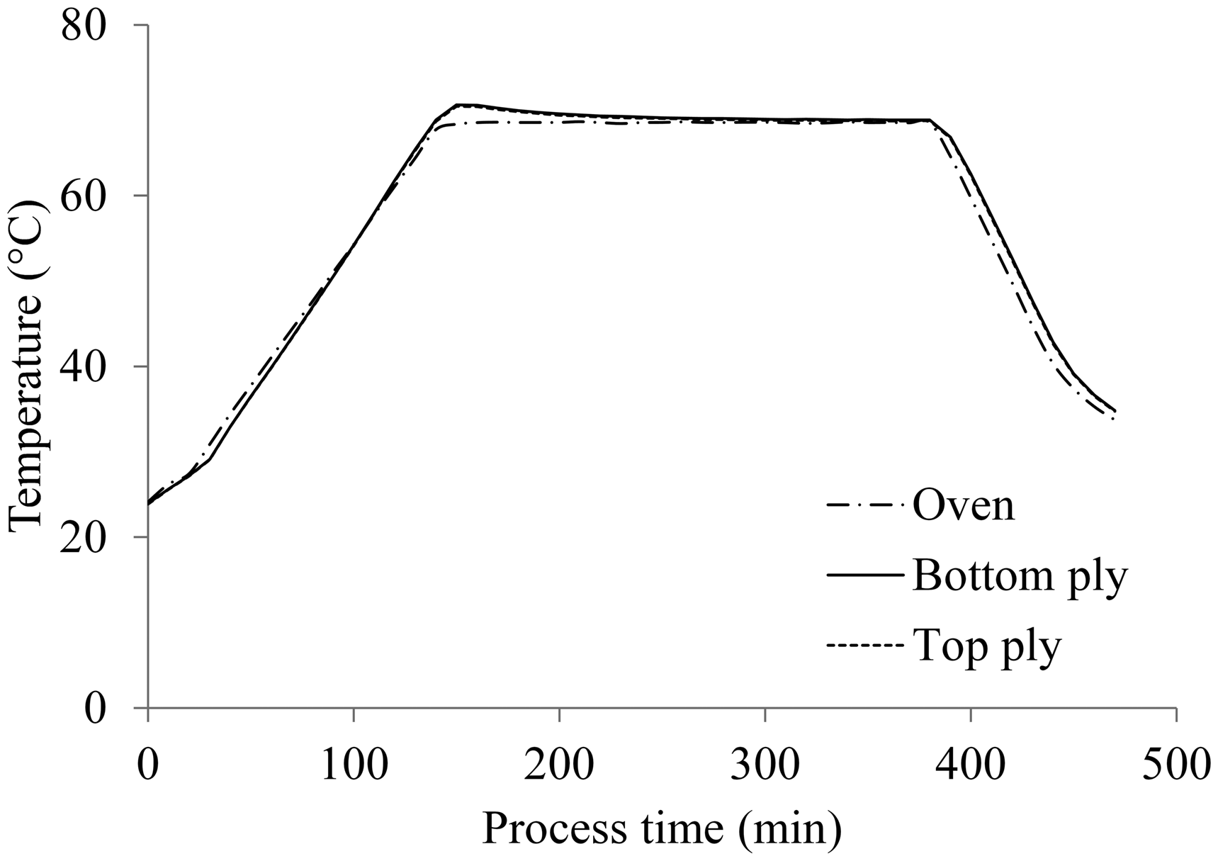
Results of validation campaign.
Residual stresses generation analysis
To understand the different warpages obtained during manufacturing a detailed analysis of residual stresses development is carried out taking advantage of the validated model. The warpage developed by the laminate after removal of the vacuum bag at the end of cure process arises from the cure induced residual stress state generated within the part during the cure cycle and due to tool-part interaction. Figure 7(a) reports the evolution of the glass transition temperature according to the cure cycle whereas Figure 7(b) depicts the resin modulus development and the residual stresses generation along x for the 0° laminas at three different locations through thickness, namely top, center, and bottom. The laminate does not develop a significant temperature gradient through thickness. Gelation point has been determined as the point where modulus of the resin starts building up and in all cases, it occurs at about 62% degree of cure although hindered by the GPa magnitude of the modulus axis in Figure 7(b). Vitrification is the point where cure cycle temperature is equal to glass transition temperature. At about 200 min, compressive stresses start developing as soon as the modulus of the resin can bear stress (between 0.5 and 1 GPa). At this point, the curing temperature is 68℃ and the Tg is equal to 58℃. Once the difference between Tg and the cure cycle temperature is about 10℃ or less compressive residual stresses start appearing within the part, at this point the modulus is about 0.8 GPa and the resin has begun vitrifying. This can be better understood by looking at Figure 4. For a given degree of cure, transition from glassy to rubbery state takes about 25℃. In between, there are several values (spanning from 4.6 GPa down to 0.04 GPa) describing the modulus of the resin during the transition. Therefore, the larger the temperature difference between the cure cycle temperature and Tg, the closer the resin modulus is to its rubber value (i.e. less capability of bearing stresses). The compressive nature of the stresses is explicable by the fact that the process is shrinkage dominated at this point (i.e. cure cycle dwell). Vitrification will be completed at about 400 min when the Tg will reach the curing temperature. The stresses developed from the vitrification point onward are due to the cool down. It results in a final compressive stress in x direction of about 22 MPa at the top, 17 MPa at the center and 12 MPa at the bottom (as shown in Table 4) ending up in a 2.0 cm warpage for the given geometry and lay-up.
Laminate 1 cure process details: (a) Tg development and cure cycle and (b) modulus evolution and residual stresses generation in 0° laminas. Residual stresses σ11 in the 0° laminas for the different cure cycles.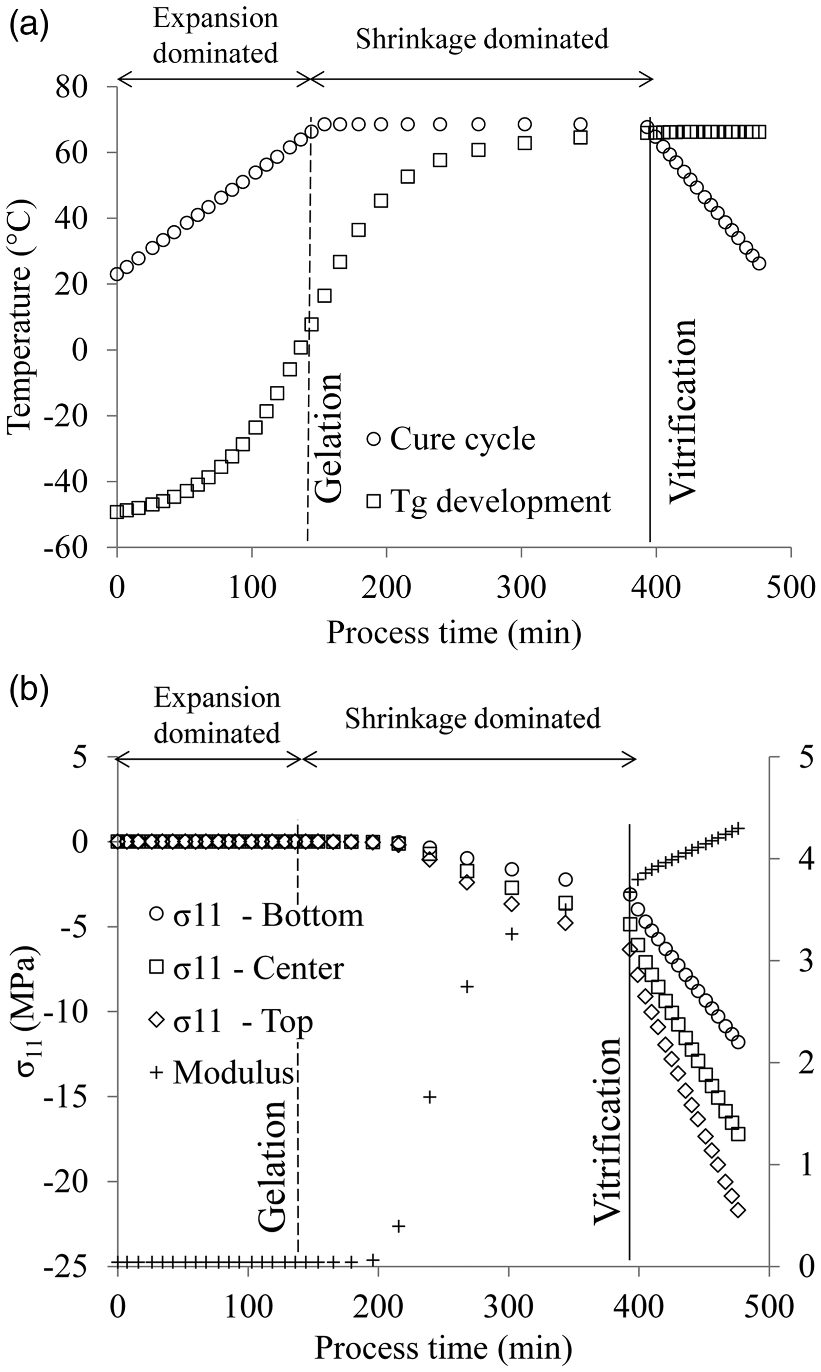
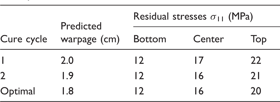
It is now of interest comparing this result with the one from Laminate 2 where a lower ramp rate was used compared to Laminate 1. Figure 8(a) reports the evolution of the glass transition temperature according to the cure cycle whereas Figure 8(b) depicts the resin modulus development and the residual stresses generation along x for the 0° laminas. The slower nature of the process leads to a different generation of residual stresses. As a matter of fact, at the time when the difference between cure cycle temperature and Tg becomes <10℃ (at about 400 min), the resin has developed a modulus of about 0.5 GPa, the cure cycle is still ramping up, and the process is expansion dominated. Having the resin developed, at this moment, a high enough modulus to carry stresses; it results into generation of tensile residual stresses during curing. Once the ramp is completed and the cure cycle is dwelling at 68℃ the process becomes shrinkage dominated and compressive stresses occur. However, the tensile stresses generated cause the final compressive state to be less severe leading to about 12 MPa at the bottom side, 16 MPa at the center and 21 MPa at the top, ending up in a smaller warpage (i.e. 1.9 cm).
Laminate 2 cure process details: (a) Tg development and cure cycle and (b) modulus evolution and residual stresses generation in 0° laminas.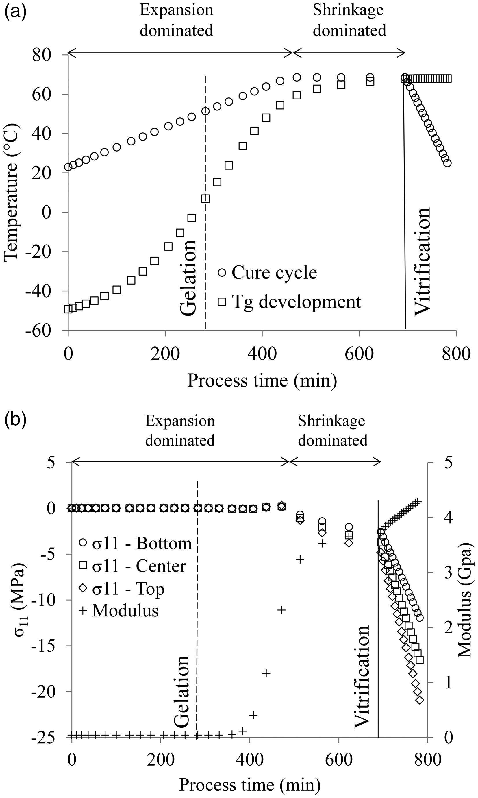
This, points out the importance of the mutual relation between cure cycle temperature and Tg but also that it is beneficial to induce tensile residual stresses in the 0° laminas to reduce the final warpage. This could be achieved by tailoring the cure cycle to have a curing temperature close enough to the current Tg of the resin when the process is dominated by expansion. By doing so, tensile residual stresses will be induced and will counteract the stresses generated during cool down. The same concept could be applied to minimize spring-in in L-shaped components. The aforementioned hypothesis will be tested in the following section.
Design of cure induced residual stresses to reduce warpage
By adopting a modified version of an already existing multi-objective methodology,
39
it is possible to identify optimal cure cycles that bring improvements in both process time and warpage by exploiting the mechanisms here presented. The optimal cure cycle identified aimed at developing Tg at the early stage of the process so that during the second ramp tensile stresses could be generated in the 0° laminas. The cure cycle dictates a quick ramp at 1.9℃/min to a first dwell of 65℃, the dwell temperature is then held for 2 h and 30 min to allow the Tg to develop for the given temperature. At this time a second ramp rate, slower than the first (i.e. 1.7℃/min), is prescribed up to 73℃, the second dwell is kept for 40 min; the cool down to room temperature is performed at 0.5℃/min as for the other cases. Figure 9(a) reports the evolution of the glass transition temperature according to the cure cycle whilst Figure 9(b) depicts the resin modulus development and the residual stresses generation along x for the 0° laminas. The final degree of cure obtained for the laminate is 91%. At about 170 min, the cure cycle designed is able to introduce tensile stresses within the part as desired. At this point in time, the modulus is about 2 GPa therefore the amount of tensile stresses introduced is significant (between 1 and 4 MPa). Moreover, since the resin at this point has reached 87% degree of cure, the following shrinkage dominated segment does not introduce significant compressive stresses. The final warpage obtained is of 1.8 cm, which is 10% less than the one obtained using MRCC. The final compressive state is reported in Table 4. Furthermore, the process time is also reduced down to 320 min, which corresponds to 33% reduction compared to MRCC. Therefore, the concept of introducing process induced stresses can be implemented within a rigorous multi-objective optimization methodology that could lead to Pareto sets, which would gather a number of best trade-off between the objectives each one obtained applying a different cure cycle.39,40
Two dwell cure process details: (a) Tg development and cure cycle and (b) modulus evolution and residual stresses generation in 0° laminas.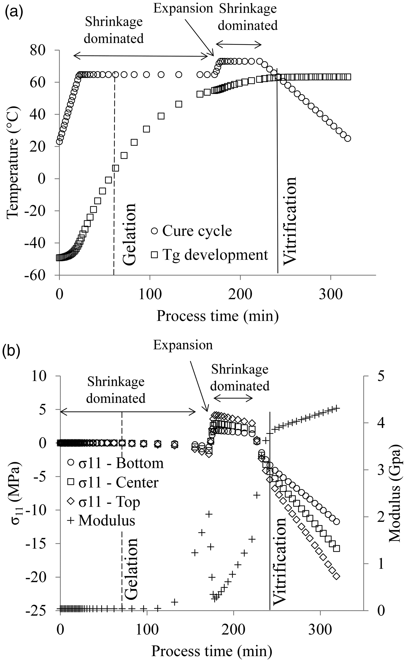
Conclusions
In this paper, the thermo-mechanical material characterization of the two component system Airstone™ 780E epoxy resin and 785H Hardener has been successfully carried out. The corresponding sub-material constitutive models have been built to fit the experimental data. The material properties development has been described as a function of both temperature and degree of cure. A coupled thermo-mechanical model able to predict residual stresses formation has been implemented in the commercial FE solver Marc.Mentat. The FE model has been successfully validated by manufacturing three asymmetric laminates following different cure cycles, and comparing the measured warpage with the FE predictions.
The detailed analysis of the cure induced residual stresses brings up the significant importance of the mutual relationship between cure cycle temperature and glass transition temperature, which determine the physical state (i.e. glassy/rubbery) of the material, which translates into a specific resin modulus value. Consequently different levels of residual stresses can develop. Furthermore, it puts forward the idea that residual stresses can be engineered within the part at the design stage by selecting an adequate cure cycle that aims at generating residual tensile stresses in 0° laminas that oppose to the compressive ones generated during cool down; 10% reduction in warpage and 33% reduction in process time is reached compared to MRCC solution when this concept is implemented into cure cycle design. The paper also suggests that key to achieve this is to have a cure cycle that brings the modulus of the resin at a state in which it can bear stresses during an expansion-dominated segment of the cure cycle (i.e. often occurring during the ramp rate that leads to final dwell). The considerations addressed in the current paper can be extended to the manufacturing of L-shaped components, which are likely to develop spring in. The introduction of designed residual stresses in this case would avoid the need for costly modified molds that try to compensate the spring in of the part. Although the present study focuses on the Airstone™ 780E epoxy resin and 785H Hardener system, the current concept is expected to be applicable also to other epoxy resin systems. The findings contribute to reduce wasted material and therefore to a more sustainable manufacturing practice, to increase process efficiency and the final quality of the manufactured parts. Finally, it shed lights onto mechanisms that dictates the onset of residual stresses during the curing process, paving the way for more effective and comprehensive optimization of the cure cycle for the reduction of final distortion and cure time for a given material and lay-up.
Footnotes
Acknowledgements
The data required to reproduce the findings in the paper are available through the Dutch Universities of Technology repository, http://researchdata.4tu.nl/home, with ![]() . The author would like to acknowledge Dr Alexandros Skordos for the useful intellectual discussions.
. The author would like to acknowledge Dr Alexandros Skordos for the useful intellectual discussions.
Declaration of Conflicting Interests
The author(s) declared no potential conflicts of interest with respect to the research, authorship, and/or publication of this article.
Funding
The author(s) disclosed receipt of the following financial support for the research, authorship, and/or publication of this article: This work is supported by ADEM project Innovation Lab.