
Abstract
This paper reports on a modified pultrusion process where the conventional resin bath was replaced with a custom-designed, enclosed resin impregnation unit. A feature of this modified production process is that the rovings were spread, prior to impregnation, using a compact fibre spreading unit. The resin impregnator was designed to accommodate 60 rovings of 2400 tex E-glass. The design features enabled specified modes of impregnation to be enacted including, resin-injection, pin-impregnation, capillary-impregnation and compaction. The impregnator was designed to accept pre-mixed resin from a pneumatically activated pressure-pot or a custom-designed resin delivery system. Pultrusion trials were conducted on a commercial machine using a conventional resin bath, the pressure-pot and the impregnation unit. The physical, mechanical and thermo-mechanical properties of the composites pultruded using the modified technique were marginally superior to those manufactured using the conventional resin bath. However, the environmental benefits of the modified pultrusion process were demonstrated to be significant.
Introduction
Pultrusion is an established manufacturing technique for the production of continuous lengths of fibre reinforced composites with a constant cross-section. Although it is difficult to pinpoint one single source to the origin of the pultrusion technology, a review of the patent literature suggests a possible evolution of the idea from a patent by Grant 1 for producing a parallel array of glass fibres involving a mould. Gray 2 developed a method for forming resin impregnated laminated stock sheets. The patent by Howald et al. 3 proposed a method for manufacturing fishing rods by covering a core material with a layer of longitudinally tensioned resin-bonded filaments. Goldsworthy and Landgraf 4 presented a detailed description of a pultrusion line involving a stack of creels, a resin bath and a haul-off unit.
Pultrusion is used to produce a range of profiles including solid rods, hollow tubes, flat sheets, complex profiles such as window frames and load-bearing structures for bridges. The pultrusion market is predicted to grow to U$ 1.7 billion by 2018 with growth being dominated by industrial sectors such as transportation, civil infrastructure and construction.
5
A schematic illustration of a typical resin bath-based pultrusion production line is shown in Figure 1.
Schematic illustration of an experimental setup for a conventional resin bath-based pultrusion process. The key components are coded as follows: (i) creels; (ii) chopped strand mats; (iii) creel stand; (iv) eyelets; (v) guide plate-I; (vi) guide plate-II; (vii) dip-type resin bath; (viii) plunger; (ix) pre-forming guides; (x) drip tray; (xi) die; (xii) heating elements; (xiii) control system; (xiv) cleat-type tractor puller; (xv) cutter; and (xvi) vacuum-based debris collection device. The cross-sectional profiles at specified locations are illustrated in the insert on the top of the pultrusion line.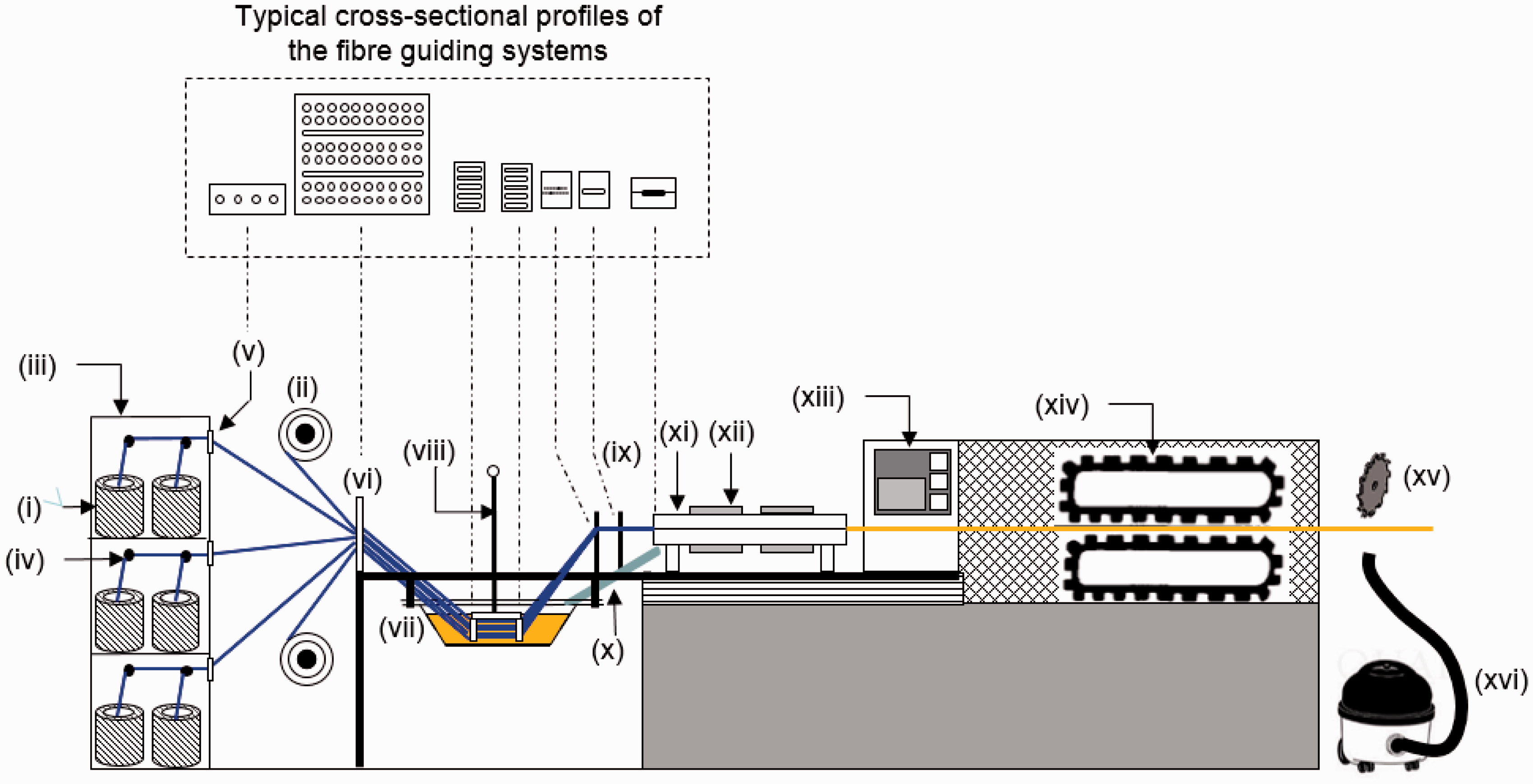
With reference to Figure 1, the bulk of the reinforcements consists of continuous rovings which are usually supplied from ‘centre-pull’ creels (item i). In other words, the roving is extracted from the bore of the creel as opposed to the outer circumference. In addition to the rovings, layers of continuous filament mats (item ii) are used to improve the transverse strength of the pultruded composite. The creels are placed on a stand (item iii) and the rovings are threaded through guide plates (item v and vi) via eyelets (item iv) to prevent them from entangling. The materials used for the eyelets are generally ceramics, steel, polytetrafluoroethylene or ultra-high molecular weight polyethylene. The guide plates (items v and vi) are generally made from polypropylene, or high-molecular-weight polyethylene. The rovings are then threaded through the plunger (item viii). A plunger is used to submerge the rovings into and out of the resin bath (item vii) as required. The impregnated rovings exit the resin bath and the excess resin is squeezed out by passing them through pre-forming guides (item ix). The pre-forming guides are generally made from one of the above-mentioned polymers or steel and their profile resembles the shape of the die. The pre-forming guides not only remove excess resin from the rovings but also consolidate them to the required shape prior to entering the die. The number and the spatial arrangement of the pre-forming guides depend on the complexity of the profile. A drip tray (item x) is used to channel the resin that is squeezed out from the impregnated rovings at the pre-forming guides and die back to the resin bath. Chrome-plated matched metal dies (item xi) are used to consolidate, shape and cure the impregnated rovings. The heat required for curing the impregnated rovings is provided via strip heaters (item xii) attached to the die, and the exotherm that is generated as the resin cross-links. The cured pultruded profile is pulled via either a continuous cleat-type tractor puller (item xiv), continuous belt-type tractor puller or reciprocating-pullers. Finally, the pultruded composite is sectioned to the required length by a cut-off saw (item xv). A vacuum-based suction device (item xvi) is generally used to collect the debris from the sectioning operation.
The above-mentioned production technique will be referred to as conventional pultrusion where the resin bath is used to impregnate the rovings. The next section provides a description of the modified pultrusion process. A detailed account is also given on the design aspects of the impregnator with regard to the modes of impregnation experienced by the rovings as they were traversed through the rig.
The modified pultrusion process
Description of the equipment
The primary difference between the conventional and the modified pultrusion process is that in the latter case, the large open-top resin bath is replaced with a compact custom-designed enclosed impregnator. The impregnator was designed to fulfil the following practical requirements: (a) increase the through-thickness impregnation by using partially spread rovings; (b) control over the volume of resin that is deposited on the spread rovings; (c) enable a combination of pin, injection and capillary-impregnation within the impregnator; (d) facilitate easy threading of the rovings; (e) easy dismantling and cleaning; (f) minimal dead-space to prevent the resin from stagnating; (g) impose minimal tension on the rovings; and (h) capable of accommodating a variety of resin delivery systems. These issues were considered in designing the impregnator rig. A schematic illustration of the key components of the modified pultrusion equipment is shown in Figure 2(a).
(a) Schematic illustration of the modified pultrusion concept. The key components are coded as follows: (i) creels; (ii) rovings; (iii) creel stand; (iv) eyelets; (v) guide plate-I; (vi) guide plate-II; (vii) fibre spreading device; (viii) resin impregnator; (ix) resin dispenser; (x) static mixer; (xi) die; (xii) heating elements; (xiii) control system; (xiv) cleat-type tractor puller; (xv) cutter; (xvi) debris collection device; and (xvii) feedback control system to enable synchronisation between the puller and the resin dispensing unit. The coding for resin dispenser (item ix) is as follows: (a) isocyanate reservoir; (b) polyol reservoir; (c and d) recirculation gear pumps; (e and f) metering gear pumps; and (g) manifold. (b) Schematic illustration of the compact fibre spreading rig. (c) Schematic illustration of the movement of the centre-roller to control the degree of fibre spreading: setting-I: fully open. (d) Schematic illustration of the movement of the centre-roller to control the degree of fibre spreading: setting-II: fully closed. The degree of fibre spreading was measured at roller-3. (e) Schematic illustration of the compact fibre spreading rig and resin impregnation unit.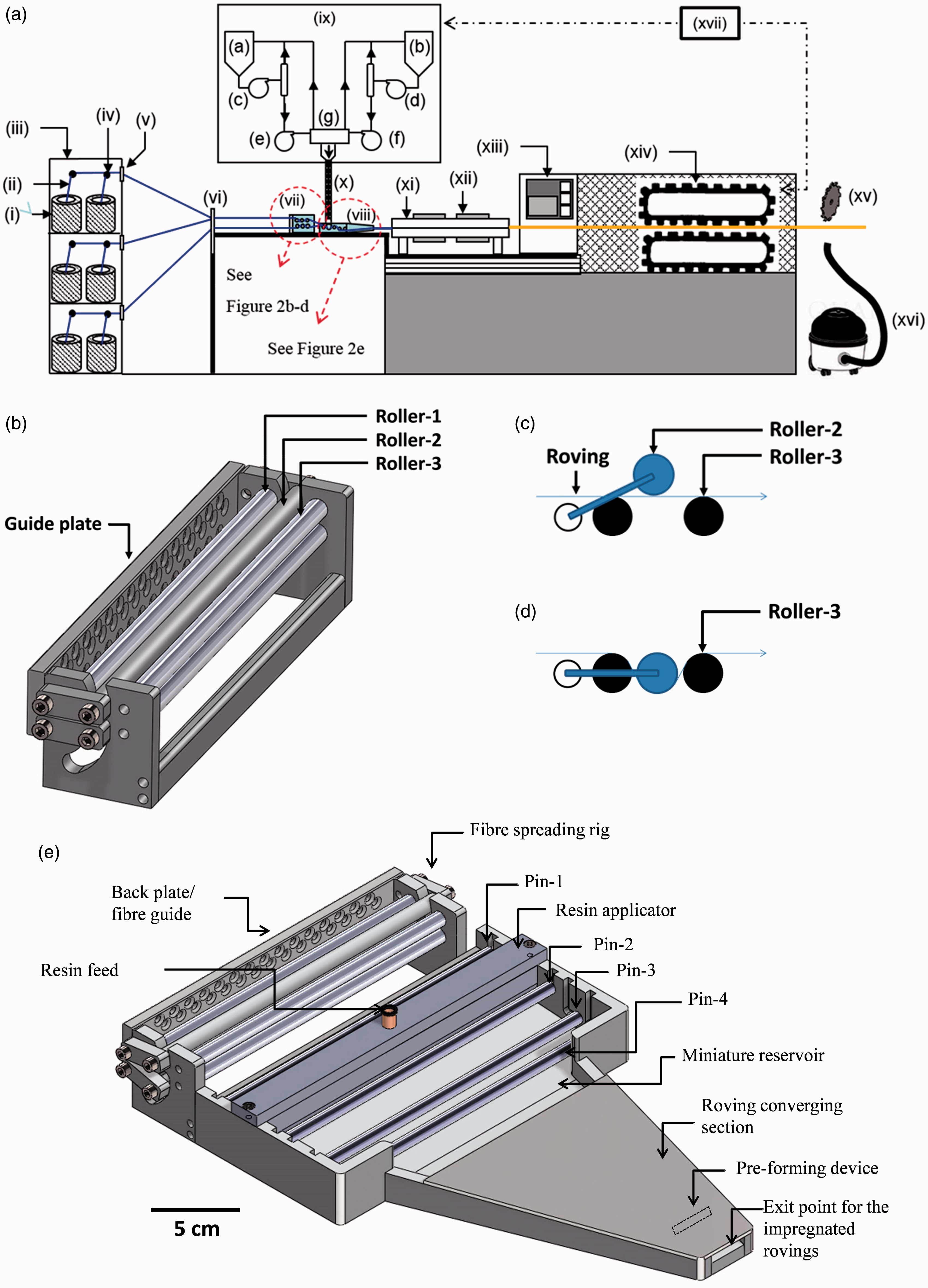
With reference to Figure 2(a), the multiple creels (item i), where the fibre-ends are extracted via centre-pull (item ii), are housed in a creel-stand (item iii). The fibre-ends from each creel (item ii) are guided through eyelets (item iv) which are attached to the creel stand. The rovings (item ii) from the creel stand are directed to the first guide plate-I (item v) followed by guide plate-II (item vi). The rovings from guide plate-II are drawn through a custom-made fibre spreading unit (item vii) and then are directed to the resin impregnation unit (item viii).
Compact fibre spreading unit
With reference to Figure 2(a), a magnified view of the compact fibre spreading rig is illustrated in Figure 2(b). The mode of operation of this rig is shown in Figure 2(c) and (d). The details of a mechanical fibre spreading unit were presented in Irfan et al.. 6 The outcome of that study was used to design a compact version that could be integrated on the pultrusion line. The primary motivations for spreading the filaments in the rovings were to: (i) reduce the nominal thickness of the bundle (by spreading) and enhance the through-thickness impregnation rate; and (ii) present a ribbon of spread fibre bundles, without any segmentation or gaps, when they reach the resin impregnation unit.
With reference to Figure 2(b), the compact fibre spreading unit consisted of a PTFE guide plate and two series of aluminium pins that were housed in an aluminium frame. The guide plate consisted of 60 recessed guide-holes divided into two sections of 30 vertically offset holes per section. The upper section of holes carried up to 30 rovings to the top series of rollers, and the lower series of holes fed rovings to the bottom series of rollers. The offset in the location of the hole was designed to position individual rovings into a parallel alignment upon entry to the ‘spreading’ rollers. Each of the two series of three aluminium rollers were designed to be rotated independently, and the centre roller (roller 2 in Figure 2(c)) was fully adjustable, allowing control over the trajectory of the rovings, thus increasing the tension, friction and contact length. The mode of operation for the upper series of rollers is illustrated in Figure 2(c) and (d). The lower set of rollers operated in an identical manner but in the opposite direction.
As can be seen in Figure 2(c), the roving is directed over rollers 1 and 3, thus allowing the adjustable roller, roller 2, to alter the trajectory of the roving up to the maximum deflection shown in Figure 2(d). As the tension on the rovings was increased, a degree of spreading was induced on each of the rovings.6,7 A balance had to be reached on the applied tension and the damage can be induced in the rovings.
Resin impregnator
The resin impregnation unit was designed to accommodate 60 (2400 tex) or 30 (4800 tex) E-glass rovings. The number of rovings was selected on the basis of the dimensions of the profile of the die (32 mm × 2.2 mm) that was available.
A magnified view of the resin impregnator is shown in Figure 2(e). The trajectory of a roving through the impregnator is illustrated in Figure 3(a); a ribbon of spread rovings from the fibre spreading unit was drawn through the resin impregnator. The resin impregnator was designed to inject the resin directly into the spread rovings,8,9 and at the same time, facilitate pin-based impregnation.10–12 After the rovings were traversed under the resin injector, their trajectory was changed as the partially impregnated fibres were passed over a pin initially and then under two further pins where they submerge in the miniature reservoir. From here on, the fibres were converged in the ‘converging section’ of the resin impregnation unit. The excess resin that was squeezed out from the fibres within the converging section of the resin impregnation unit (inclined at an angle of 5°), flows back to feed the miniature reservoir. The exit point of the impregnator was designed to be fractionally larger than the dimensions of the entry point to the die. This enabled a final squeezing action on the impregnated rovings. The resin drips emanating from the exit point of the impregnator were observed to be negligible.
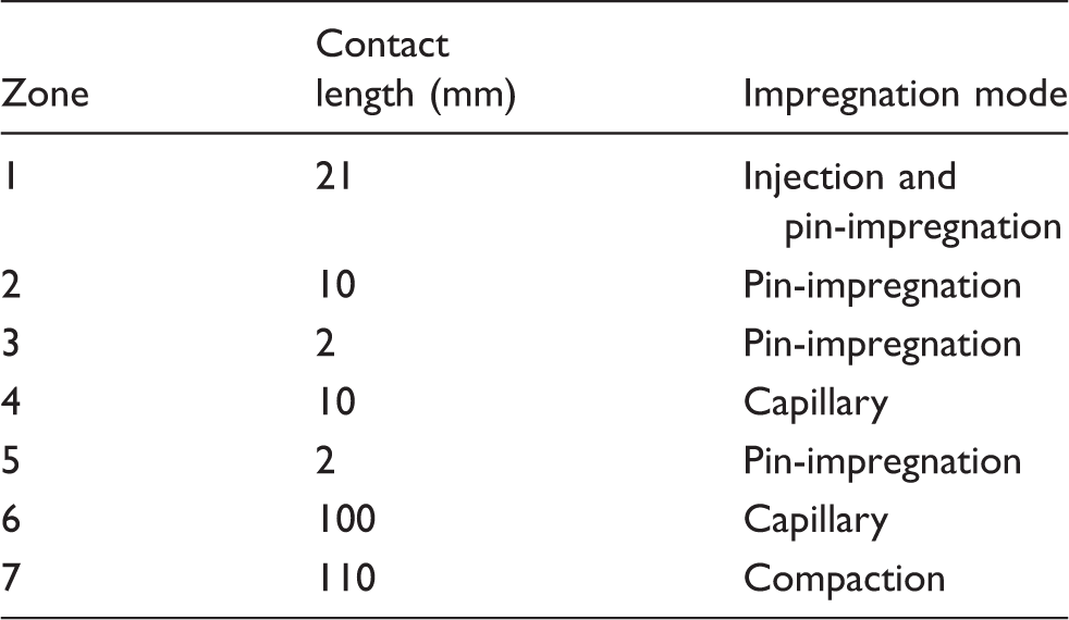
(a) Schematic illustration of the resin impregnator PUL-I showing the trajectory of rovings. The details of the coding for the different zones are summarised in Table 1. (b) Schematic illustrations of the side view of resin applicator PUL-I.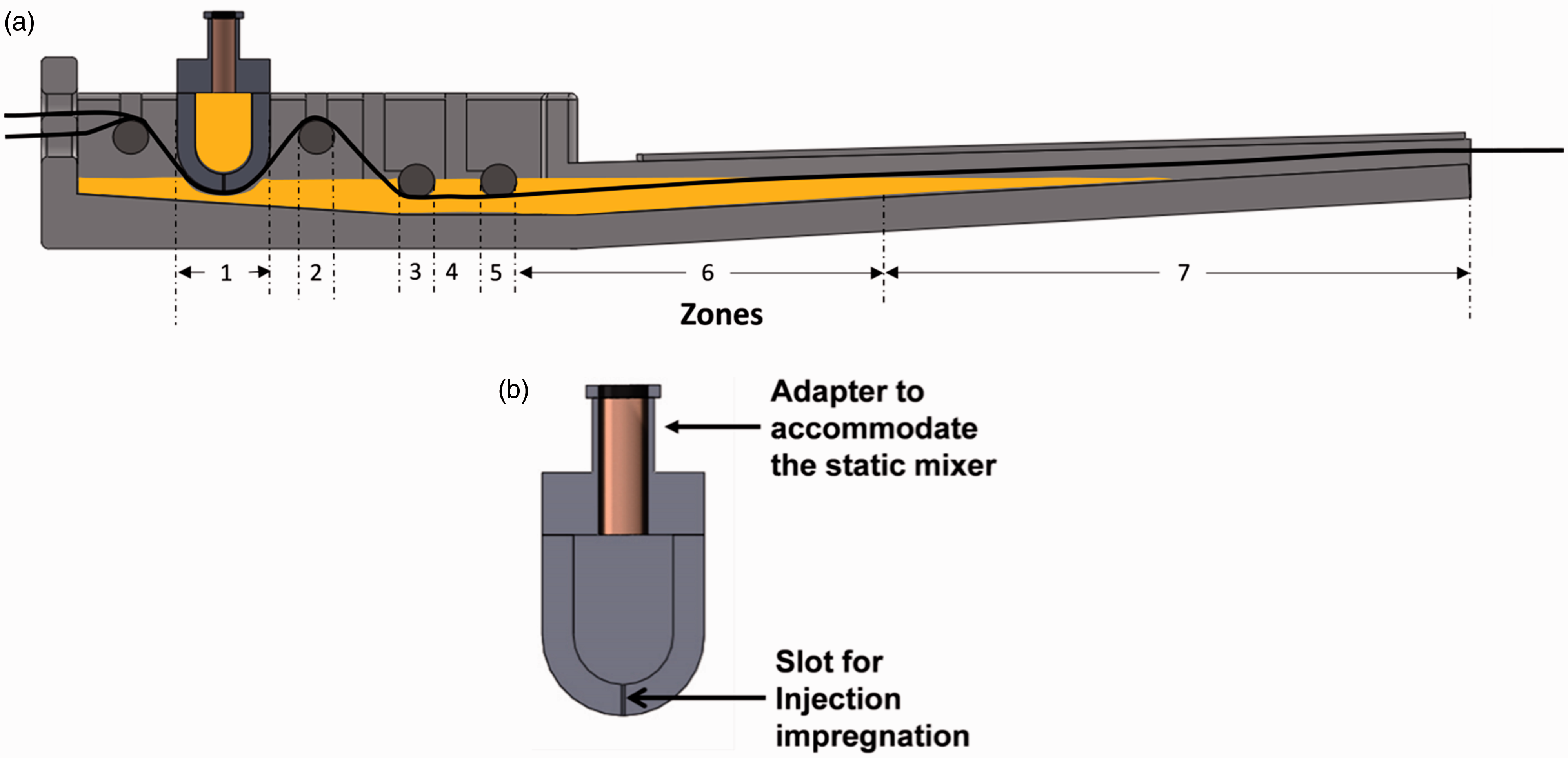
After impregnation, the rovings entered a heated die (Figure 2(a), item xi) where the impregnated rovings were consolidated and cured to produce the composite with the desired profile (rectangular in this instance with dimensions of 32 mm × 2.2 mm). The composite was hauled off from the die by a cleat-type tractor puller (item xiv). When the desired length of composite was pultruded, it was cut using a diamond-coated blade (item xv) and the debris generated during the cutting process was collected using a vacuum-based extraction unit (item xvi).
The impregnator was designed to accommodate two types of resin delivery systems: (a) a precision gear pump system; and (b) a pressure-pot.
Precision gear pump system (see Figure 2(a)): Here the resin and hardener components are stored in separate containers (items a and b) within the resin dispensing equipment (item ix). The resin dispensing unit consists of four pumps serving two circuits. The first is a recirculation circuit (item c and d) where the recirculation pumps circulate the resin and hardener (without mixing). The second set of pumps (item e and f) enables the flow of the resin and hardener, in the correct stoichiometric ratio, to a manifold (item g) which in turn directs the individual liquid streams to a static mixer (item x). The resin dispensing unit (item ix) is linked to the fibre haul-off equipment via a feedback control system (item xvii) to enable the two items to be synchronised. Pressure-pot system: Premixed resin and hardener could also be supplied to the resin impregnator via a pneumatic resin delivery system or ‘pressure-pot’. Here the resin components are mixed manually and added to the pressure-pot. The premixed resin is supplied to the resin impregnator on-demand via pneumatic pressure using a compressor. An obvious advantage of this system is the lower capital cost when compared to the resin dispenser.
The design basis for the impregnator rig
The efficiency of the resin impregnator (Figure 2(e)) was defined by a dimensionless impregnation number (Iimp). It was assumed that for a particular set of parameters including the pultrusion speed, pre-tension, resin viscosity and fibre type, the value of Iimp has to be equal to or greater than one to obtain complete impregnation. The following section presents a description of the calculations to obtain the impregnation number (Iimp) for the impregnator that was illustrated in Figure 2(e).
Calculation of the total impregnation length
Contact length and corresponding mode of impregnation for each zone of resin impregnator PUL-I.


Summary of the fixed parameters used to calculate the extent of impregnation.
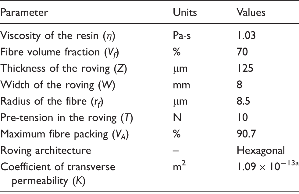
The transverse permeability was calculated using the relation proposed by Gebart. 13
Estimation of the extent of injection-based impregnation
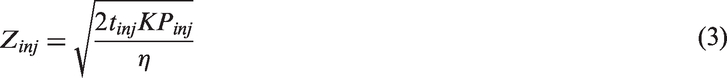
The resin was injected directly onto the surface of the spread fibre ribbon in zone-1 of the impregnator. The depth of the impregnation in the roving (Zinj) as a result of injection-based impregnation was estimated from the following relationship (integration of Darcy’s equation)
14


The estimated percentage of impregnation obtained by resin-injection as a function of the three pultrusion speeds used in this study is shown in Figure 4. The simulations were carried out for two types of resin delivery systems; pressure-pot and resin dispenser.
Simulations for the estimated resin injection as a function of the pultrusion speed.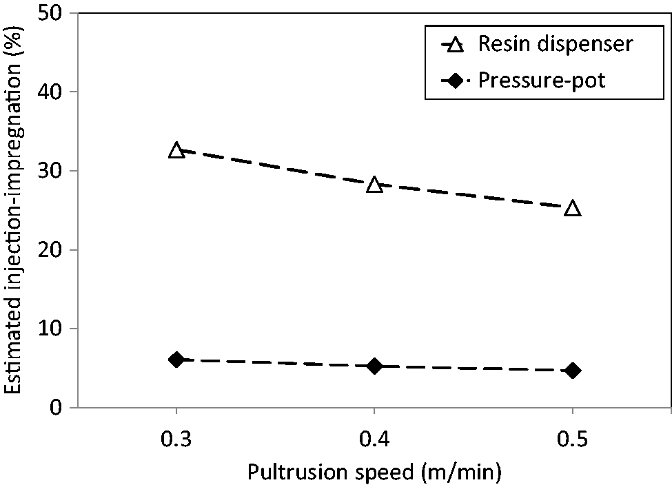
Estimation of the extent of pin-impregnation
The thickness of the roving that was impregnated via pin-impregnation was estimated using an integrated form of Darcy’s equation
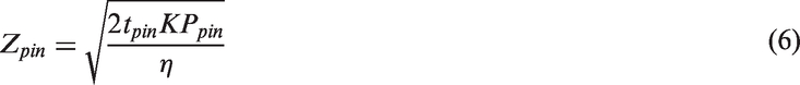


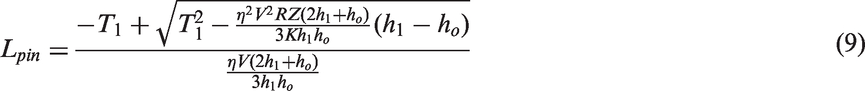
The estimated percentage impregnation obtained by pin-impregnation (Ipin) for each pin was calculated by

The total impregnation due to pin-impregnation as a function of the pultrusion speed is shown in Figure 5.
Estimated degree of pin-impregnation as a function of the pultrusion speed.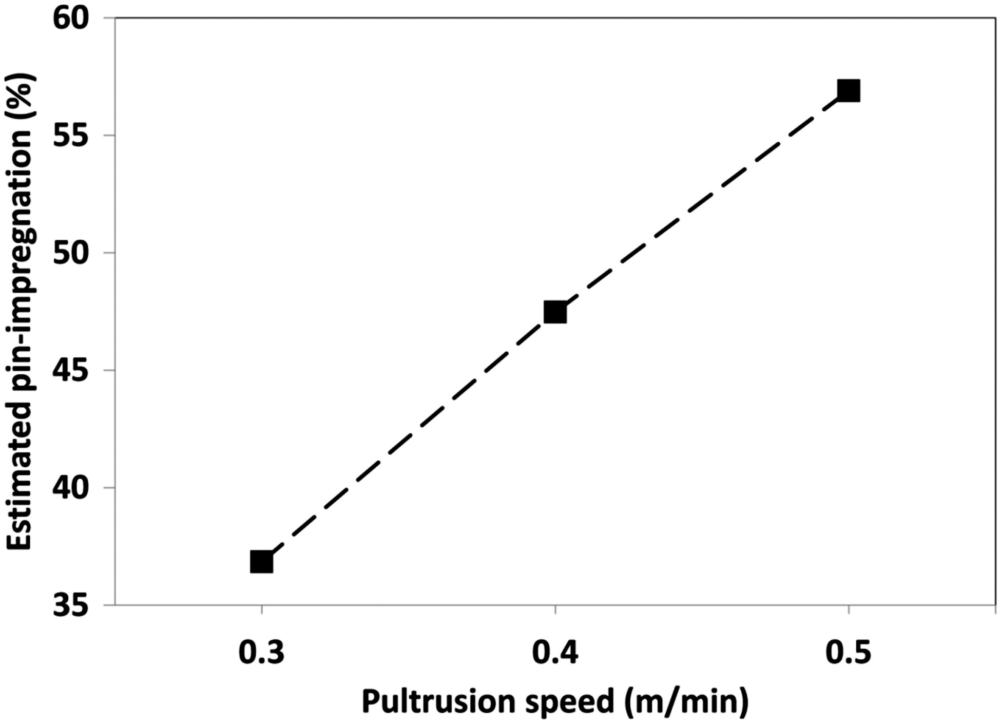
Estimation of the extent of capillary-impregnation
The zones of the resin impregnator where capillary-impregnation was deemed to take place are depicted in Figure 3(a) and Table 2. The thickness of the roving impregnated via capillary-impregnation was estimated by integration of Darcy’s equation
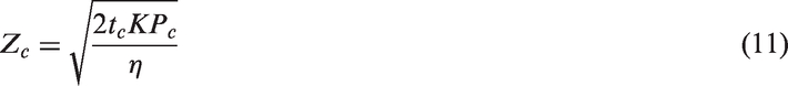

The capillary pressure (Pc) was calculated using the following equation
15


Summary of the parameters used to calculate the impregnation-zone length assuming capillary-impregnation.
Amico and Lekakou. 16
A graphical representation of total impregnation due to capillary-impregnation as a function of the pultrusion speed is presented in Figure 6.
A simulation of the estimated degree of capillary-impregnation in the resin impregnator as a function of the pultrusion speed.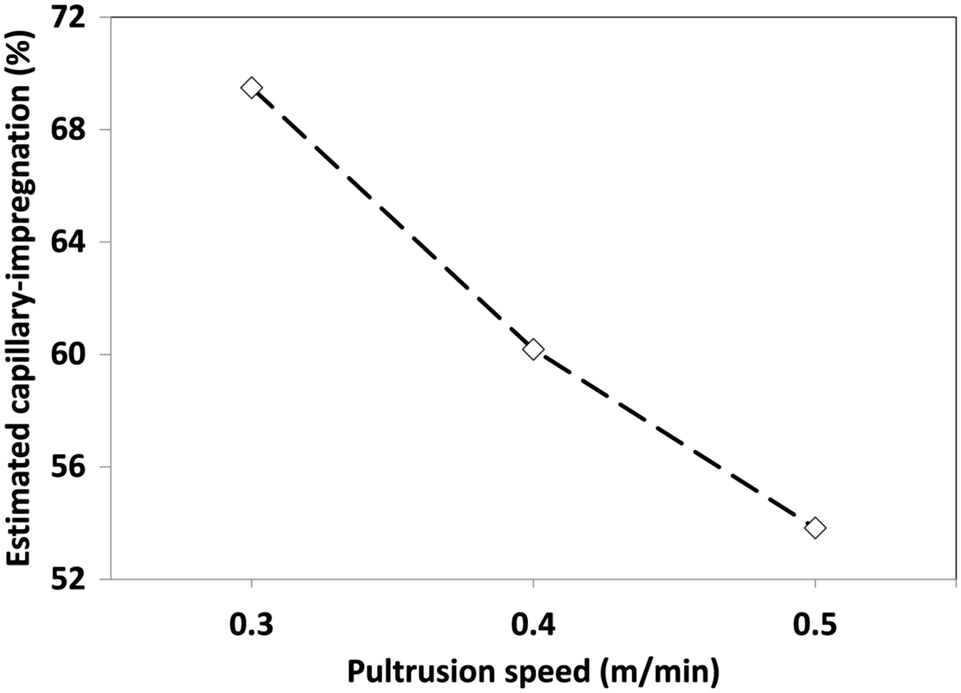
Estimation of the extent of impregnation in the converging zone
With reference to Figure 3(a), the ‘converging’ zone represents the case where the impregnated rovings start to converge prior to reaching the exit point of the resin impregnation unit. In order to estimate the pressure exerted on the impregnated rovings in this ‘converging’ zone, an approach used in the resin-injection pultrusion process was adopted. This converging section gives rise to an increase in the pressure experienced by the impregnated rovings due to compaction. 17 Brennan and Connolly 18 used transducers to measure the pressure in the resin-injection chamber. In the current study, the pressure was estimated from the parameters reported by Palikhel et al. 17
Palikhel et al.
17
reported that for a resin-injection chamber with a compression ratio of 4.0 (the resin viscosity was 0.75 Pa.s, with a fibre volume fraction of 68%), the increase in the pressure at the exit of the resin-injection chamber was 378 kPa; the resin injection pressure was 2 kPa. The length of the converging section was 0.15 m. In the current study, the assumption was made that the pressure-rise in the converging section, for the profile (illustrated in Figure 2(e)), would follow a similar trend as reported by Palikhel et al.
17
It was also assumed that the pressure at the start of zone-7 was atmospheric. The depth of the impregnation in the roving (Zcomp) as a result of impregnation due to compaction at the exit of the resin impregnator was estimated from
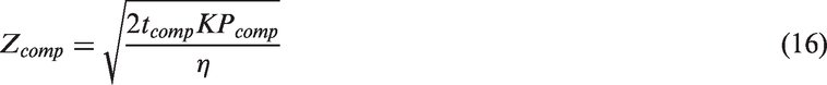
The time for the roving to undergo impregnation via fibre compaction was calculated by


The estimated impregnation obtained in the converging section as a function of the three pultrusion speeds used in this study is shown in Figure 7.
The estimated degree of impregnation in the converging section (zone-7) of the resin impregnator (see Figure 3(a)) as a function of the pultrusion speed.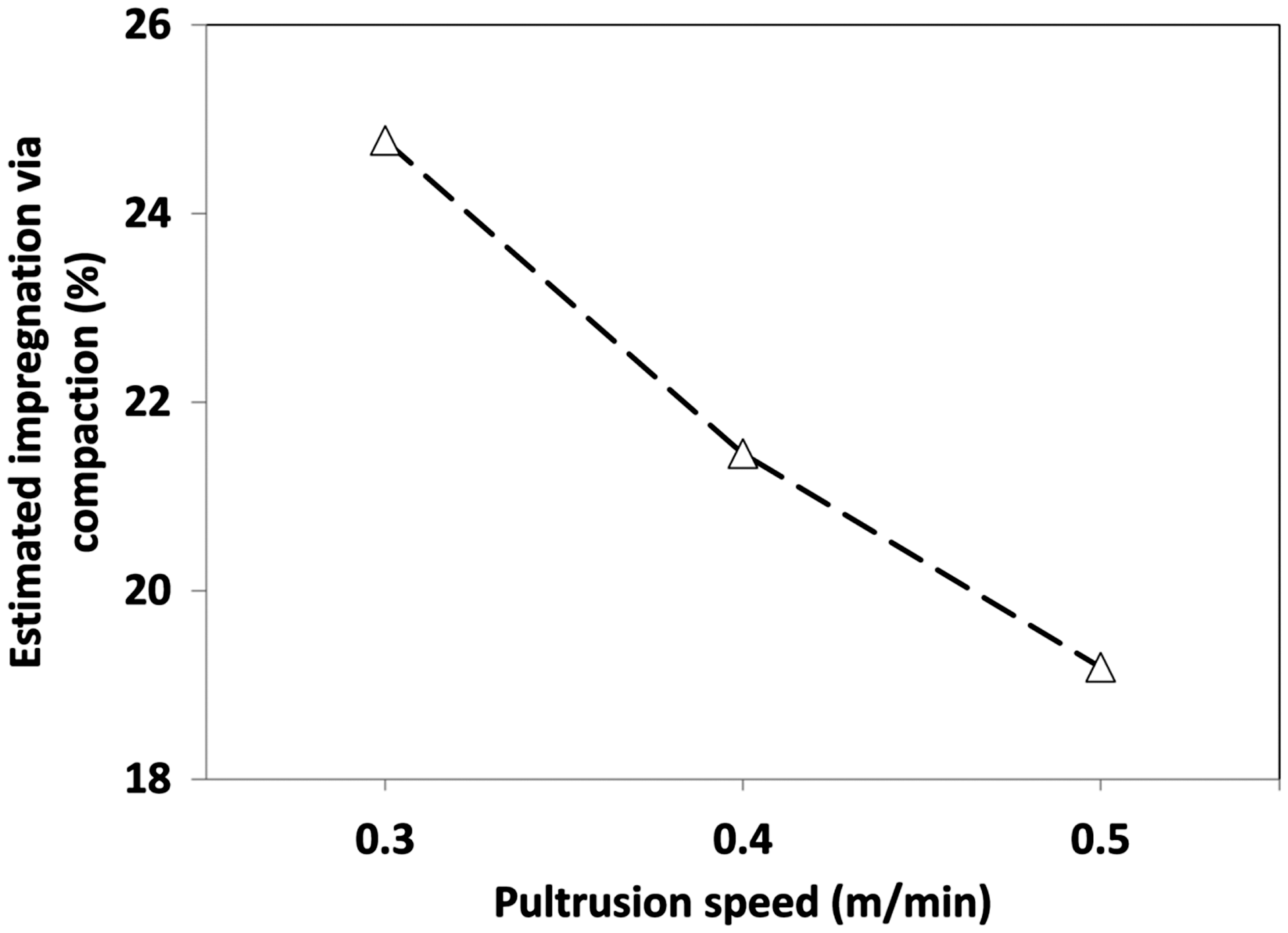
Estimation of the impregnation number
The resin impregnation number (Iimp) was determined using the following relationship

It can be seen from Figure 8 that the impregnation number for the resin impregnator is greater than unity for the three pultrusion speeds considered. A decreasing trend for the impregnation number with an increase in the pultrusion speed can also be seen.
Simulation of the estimated impregnation number as a function of pultrusion speed. The region above the horizontal dashed line represents complete impregnation.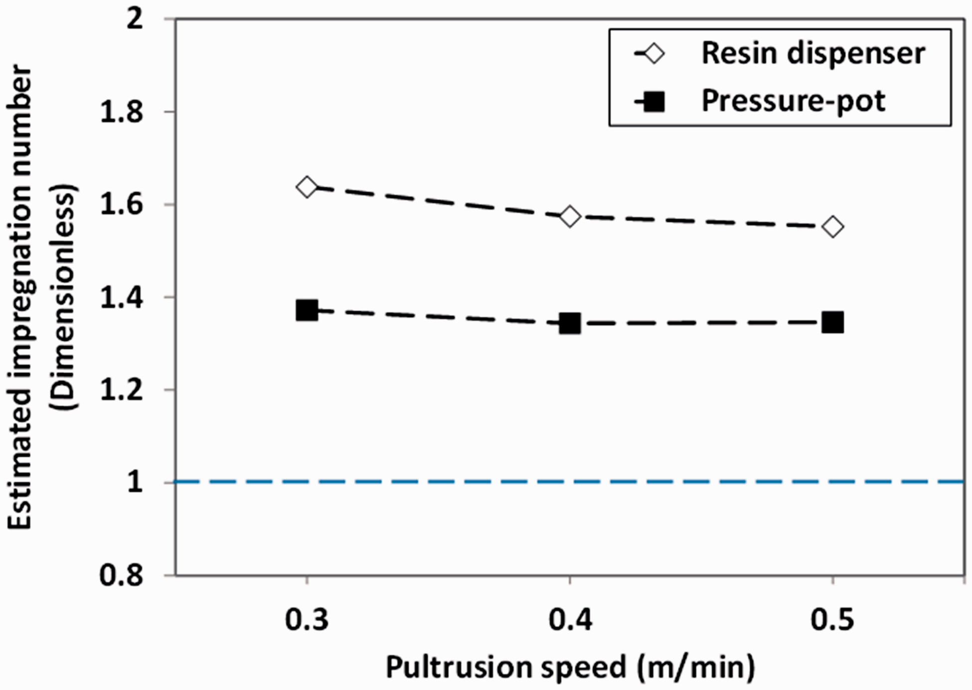
The data generated in this section coupled with the data generated from differential scanning calorimeter (DSC) were used to select the operating speeds for the pultrusion experiments. This impregnator is coded as PUL-I from hereon.
Experimental
Materials
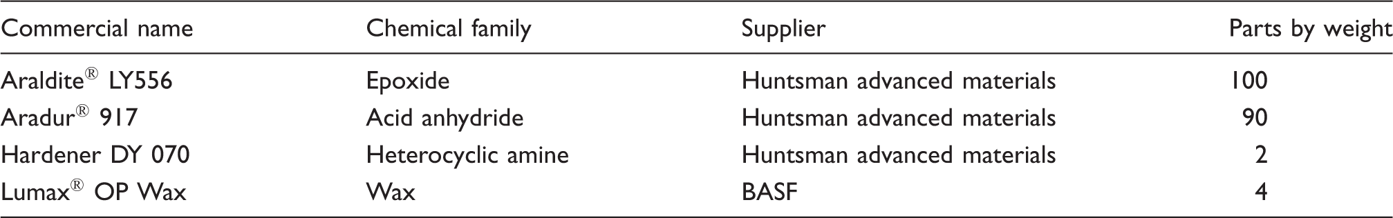
Details of the polyurethane and epoxy resin systems used in this study.
Thermal analysis (to select the die temperature)
A power-compensated DSC, Diamond-DSC, Perkin Elmer, UK, was used to study the cure behaviour of the two resin systems. The components of the resin system were mixed manually in the required stoichiometric ratio and degassed for 10 min. In the first set of experiments, the resin was cured using a dynamic mode of heating; here, the resin was heated from 30℃ to 200℃ at 5 K minute−1. The experiment was then repeated three times, using the same sample from each experiment, to determine the magnitude of any residual cure, and the glass transition temperature (Tg). In the second set of experiments, the resin systems were cured isothermally at 160℃.
Pultrusion experiments
The laboratory-scale pultrusion machine (Model PX100C-3 T) used in this work was designed and built by Pultrex Ltd. This pultrusion machine had a maximum pulling force of 3000 kg and was equipped with cleat-type tractor pullers. The maximum profile width that could be pultruded was 100 mm and the maximum haul-off speed of the machine was 4 m/min. The pultrusion machine was equipped with the option of operating 12-heating zones independently. In the current study, two heaters were attached to a 0.5 m die. A servo-motor was used to operate the pullers to maintain the required pultrusion speed. The resin dispenser was synchronised with the pultrusion machine so that it could be programmed to dispense the resin system as dictated by the pultrusion speed.
Conventional pultrusion
Detail of the conventional and modified pultrusion experiments.
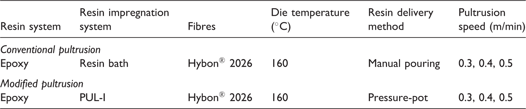
Modified pultrusion
The resin impregnator (coded as PUL-I) was used instead of the resin bath for the modified pultrusion trials. The resin was premixed and transferred to a 2 L pressure-pot that was operated by compressed air. The details of the modified pultrusion experiments are summarised in Table 5.
Evaluation of pultruded samples
The densities of the pultruded composites were determined using an OHAUS density measurement kit (Model: AP110S). The fibre volume fraction of the pultruded samples was determined by the ignition-loss method in accordance with ASTM D 2584-08. The void fraction (Vv) was determined in accordance with ASTM D 2734-03. Standard metallographic methods for potting and polishing were used for preparing the samples for optical microscopy. A Zeiss Axioskop 2 microscope was used to obtain optical micrographs of the polished pultruded samples. A dynamic mechanical analyser (DMA 242 C, NETZSCH) was used to obtain the thermo-mechanical properties of the resin system and the pultruded composites. The Tg was obtained from the peak of the loss tangent (tan δ). Each sample was clamped in the dual-cantilever fixture and heated from 25℃ to 180℃ at 3 K min−1. The experiments were conducted at 1 Hz. A minimum of three samples were tested for each of the specimen types. The inter-laminar shear strength (ILSS) of the pultruded composites was measured according to BS EN ISO 14130:1998 and the flexural strength and modulus of the composites were measured according to ASTM D 6272-08.
Results and discussion
Selection of the die temperature
The data from the DSC were used to define the temperature of the die and the pultrusion speed in conjunction with the data generated for the impregnation number. With reference to the dynamic mode of heating using the DSC, conversion curves were generated as a function of temperature using the following relationship19
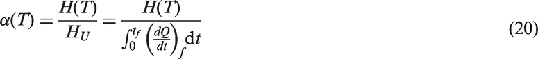
A typical thermogram obtained from a dynamic DSC heating experiment for the epoxy resin system is shown in Figure 9(a) where the onset of cross-linking is seen to commence at 55℃ with the peak at 131℃. The total enthalpy of cure (HU) was −315 J/g. A conversion curve was generated from the data presented in Figure 9(a) and is shown in Figure 9(b) where it can be seen that the degree of conversion at 160℃ was 98%. Hence, the die temperature for the pultrusion experiment with the epoxy resin system was set at 160℃.
(a) DSC thermogram for the epoxy resin obtained by a dynamic scanning experiment at 5 K/min. (b) Conversion versus temperature curve generated from Figure 9(a).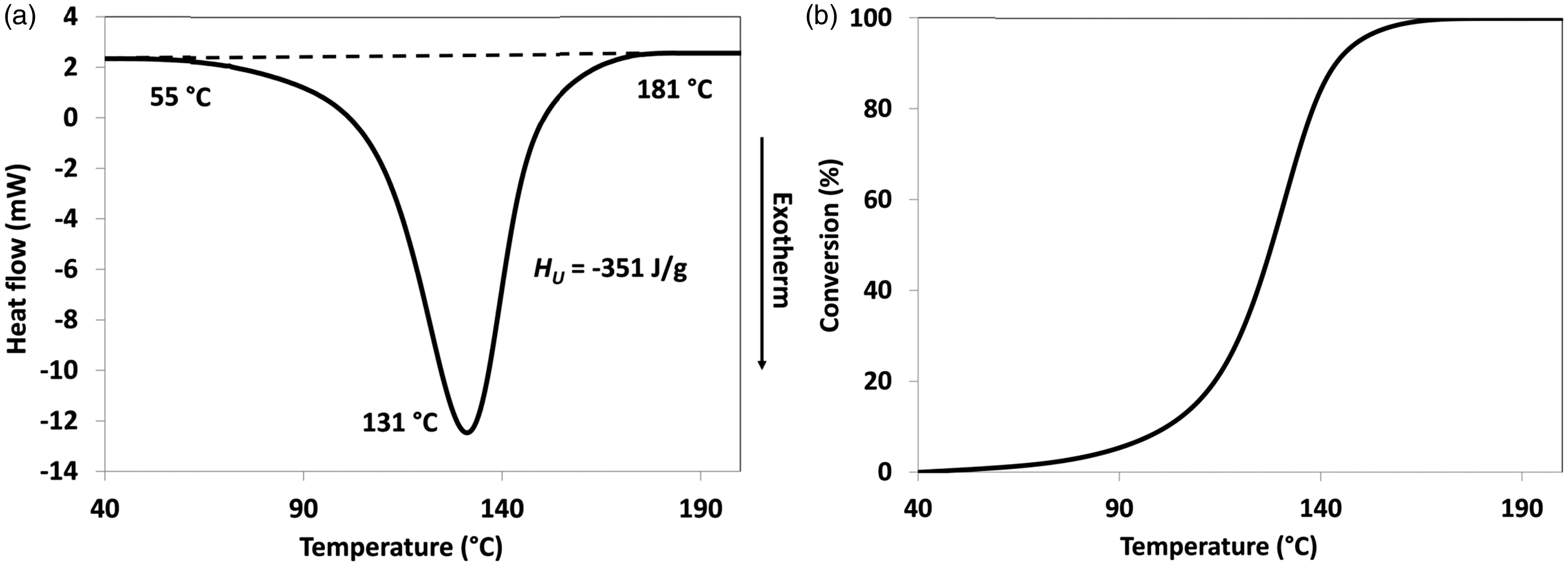
The objective of these experiments was to establish the pultrusion speed which would ensure complete curing of the resin system within the 0.5 m die. The samples were maintained at the desired isothermal value for 10 min and the conversion-time curves were generated using the following relationship19

An isothermal DSC experiment was carried out at 160℃ and the data are presented in Figure 10(a). A conversion-time curve was generated using the data presented in Figure 10(a) and it is shown in Figure 10(b).
(a) Degree of conversion for 160℃ obtained via an isothermal DSC experiment. (b) The corresponding residence time of the rovings in the 0.5 m die for the three pultrusion speed used in this study is also indicated. (c) Definition of the glass transition temperature obtained by a second DSC dynamic scanning experiment for a cured sample of epoxy resin.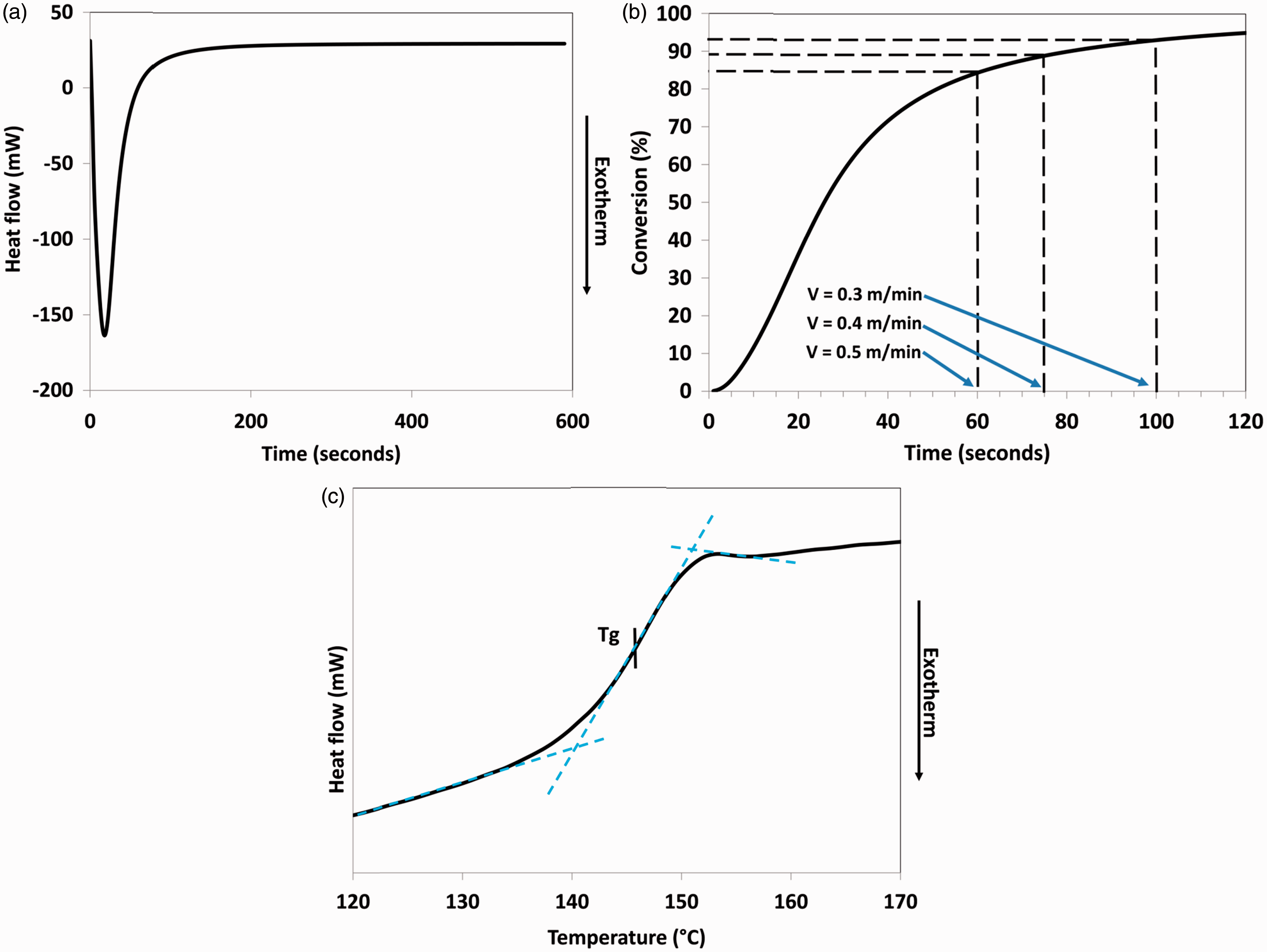
With reference to Figure 10(b), the vertical lines represent the time that the impregnated rovings reside within the 0.5 m die. It can be seen that as the pultrusion speed is increased, the extent of conversion at 160℃ is reduced. Here, the degree of conversions at the times corresponding to the pultrusion speeds of 0.3, 0.4 and 0.5 m min−1, for the 0.5 m die, were determined. It was shown that for all the pultrusion speeds used in this study, the conversion of the resin system was greater than 85%. The assumption here is that the temperature profile within the die is relatively uniform for the 2.2 mm thick composite.
The samples from the dynamic and the isothermal experiments were re-scanned from room temperature to 180℃ at 20 K/min to determine the glass transition temperatures (Tg) of the cured resin. A typical trace from the second dynamic heating of a sample is presented in Figure 10(c) where the method for defining the Tg is also indicated. The average Tg for epoxy LY556 resin from three experiments was 143.9 ± 2.1℃.
Epoxy/E-glass composites
The effect of the pultrusion speed on the physical, mechanical and thermo-mechanical properties of the composites was undertaken at 0.3 m/min, 0.4 m/min and 0.5 m/min. The simulations that were carried out to attain maximum curing indicated that the fastest pultrusion speed permissible was 0.5 m/min.
The fibre volume fractions and densities of the pultruded composites manufactured via the conventional and modified techniques at the three pultrusion speeds are shown in Figure 11. It can be seen that for a specific pultrusion method, the densities are similar; however, the densities of the modified pultrusion technique are higher than that observed for the conventional method due to the differences in the fibre volume fractions. The fibre volume fraction for the resin bath samples was approximately 65%. However, the fibre volume fraction obtained with the modified pultrusion process was approximately 70%. The primary reason for the observed variations in the fibre volume fraction in the conventional and modified techniques can be related to the number of rovings that were used in each case. The die profile used in this study required each roving to be introduced into the die in a sequential fashion where manual hauling of the dry fibres was possible for up to 20 rovings. Further increases in the number of rovings required the haul-off unit on the pultrusion machine to be used. With conventional resin bath-based pultrusion, it was only possible to introduce 50 rovings by this process, whereas in the case of the modified technique using the impregnator, 52 rovings were accommodated without encountering any blockages at the entry point of the die.
Fibre volume fractions and densities for the pultruded epoxy/E-glass composites produced at three pultrusion speeds using the resin bath and resin impregnator PUL-I.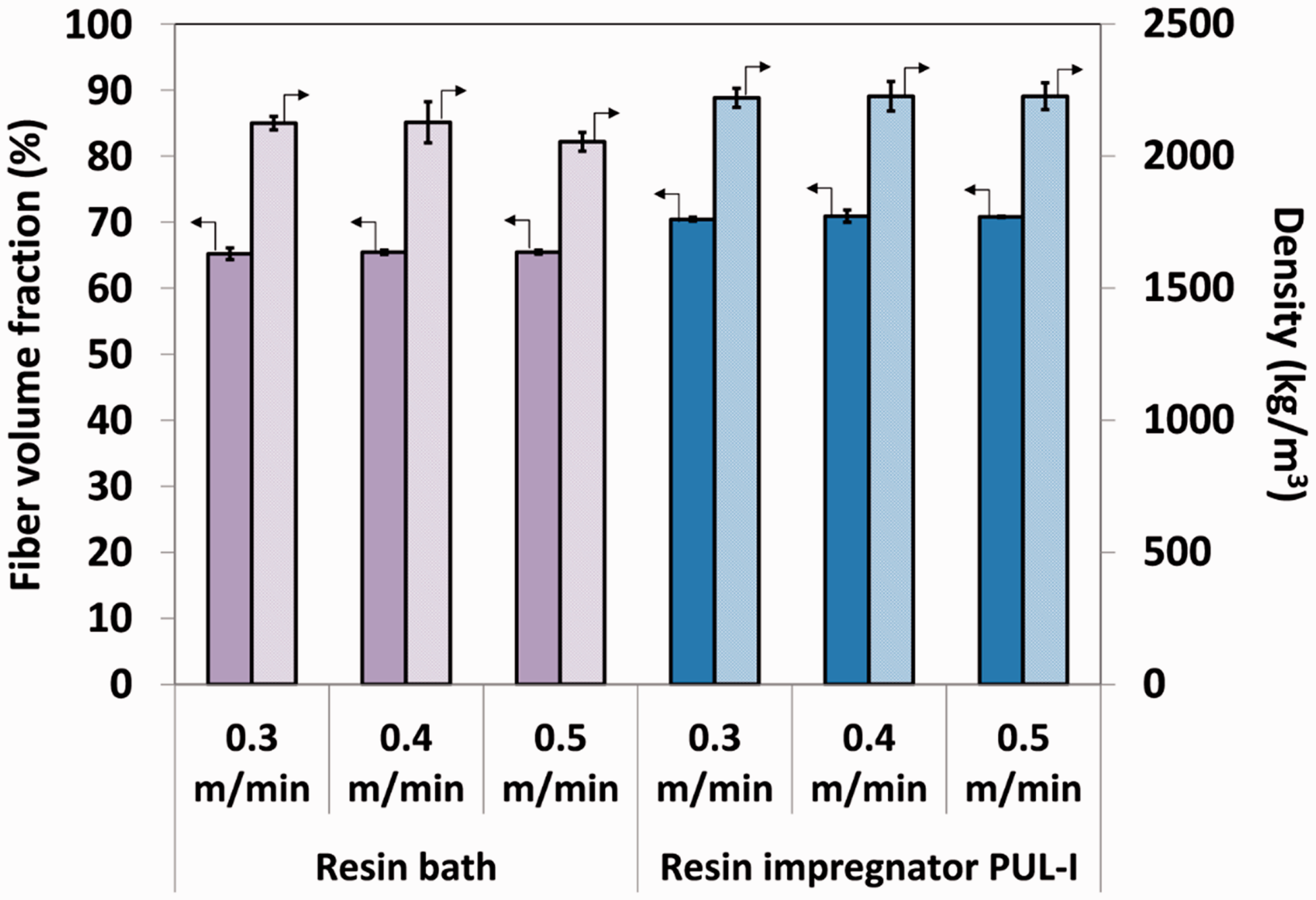
As seen in Figure 12, the void fractions in the composites produced using the modified pultrusion technique were slightly lower than those produced via conventional pultrusion. Within the dataset of the void fractions of the composites produced via resin impregnator PUL-I, a marginally lower void content is observed at 0.4 m/min. The reasons for the lower void fractions observed in the composites manufactured using the modified pultrusion technique may be related to a more efficient convergent zone and the various modes of impregnation that the rovings experience. The spreading of the filaments prior to impregnation is also likely to have contributed to the observed lower void content.
Void fractions for the pultruded epoxy/E-glass composites produced at three pultrusion speeds using the resin bath and resin impregnator PUL-I.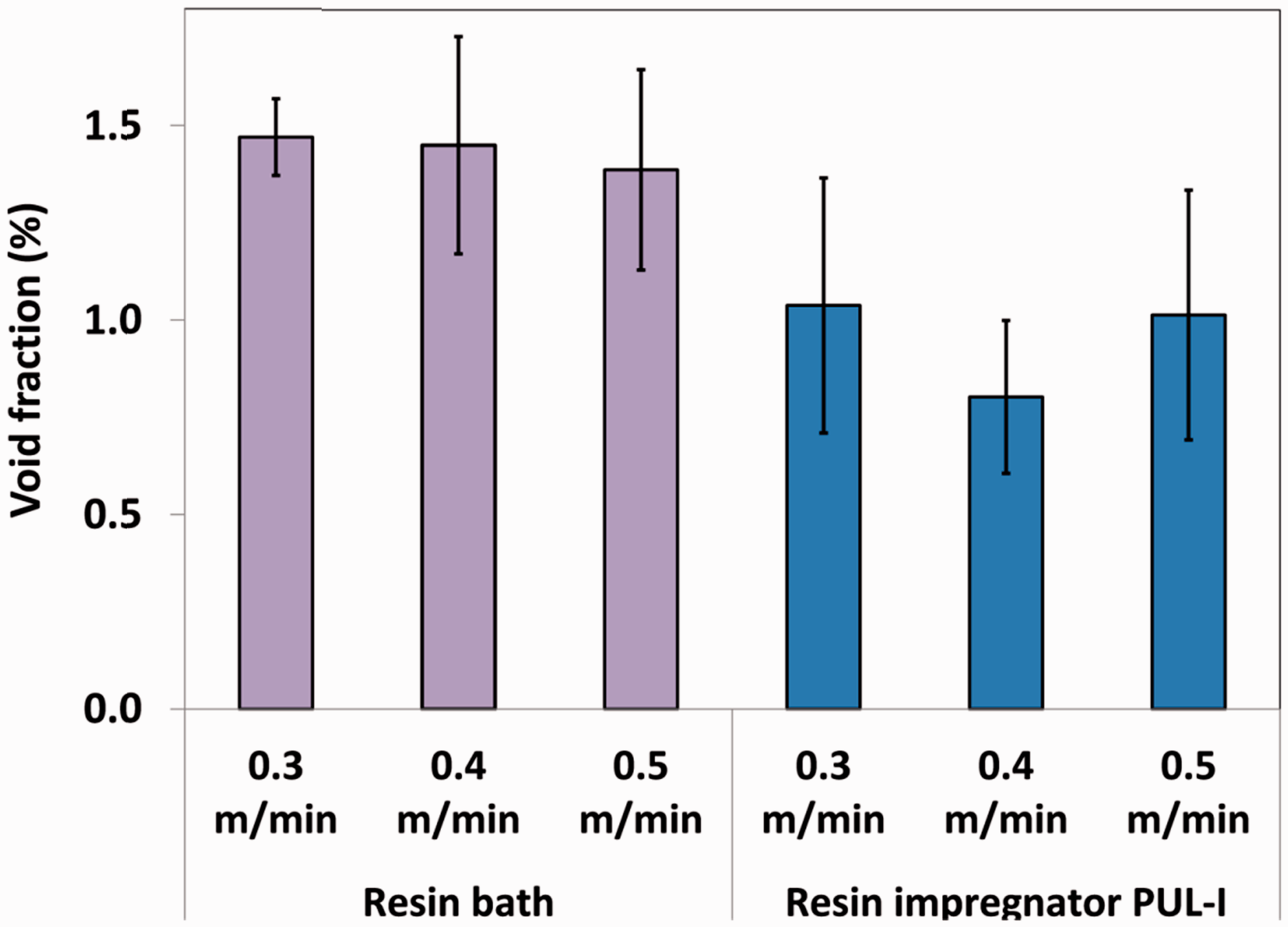
Typical micrographs of the epoxy/E-glass composites produced at three pultrusion speeds are shown in Figure 13(a) to (f); Figure 13(a), (c) and (e) and (b), (d) and (f) represents those manufactured using the conventional and modified methods respectively at the three specified pultrusion speeds.
Representative micrographs of the epoxy/E-glass composites produced at three pultrusion speeds. (a) conventional pultrusion using resin bath at 0.3 m/min; (b) modified pultrusion using resin impregnator PUL-I at 0.3 m/min; (c) conventional pultrusion using resin bath at 0.4 m/min; (d) modified pultrusion using resin impregnator PUL-I at 0.4 m/min; (e) conventional pultrusion using resin bath at 0.5 m/min; and (f) modified pultrusion using resin impregnator PUL-I at 0.5 m/min.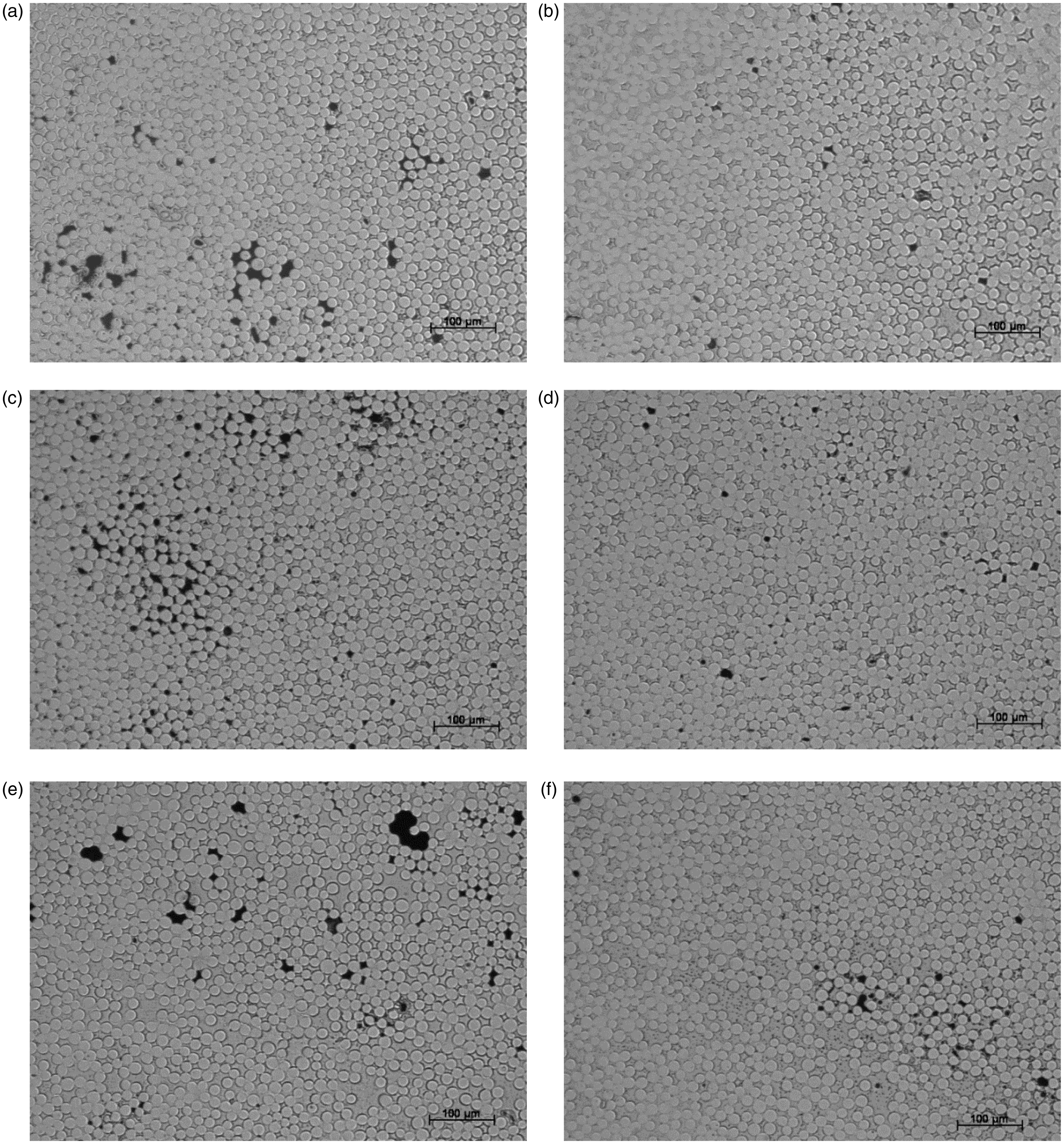
The lower void content is evident in the micrographs shown in Figure 13(b), (d) and (f) for the modified pultrusion process. This conclusion was reached after inspecting over 5 polished sections for each pultrusion type and 15 individual frames at a series of magnifications.
The lower void content for the modified pultruded composites is also manifested in the mechanical properties of the composites produced with regard to the flexural strength and flexural moduli and the storage moduli. The properties of the composites manufactured using the modified pultrusion process were equal or marginally better than those manufactured via the resin bath method.
The flexural strengths and moduli of the composites produced at the three pultrusion speeds are shown in Figures 14 and 15, respectively. The original and the normalised data, normalised to 60% fibre volume fraction, are included to enable comparison. It can be seen that in both graphs, the values for the composites produced via modified pultrusion are marginally better than those produced by conventional pultrusion.
Flexural strengths for the pultruded epoxy/E-glass composites produced at three pultrusion speeds using the conventional and modified manufacturing technique. Flexural moduli for the pultruded epoxy/E-glass composites produced at three pultrusion speeds using the conventional and modified manufacturing techniques.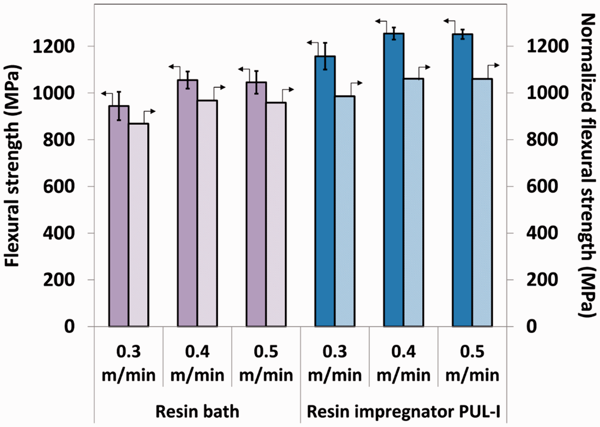
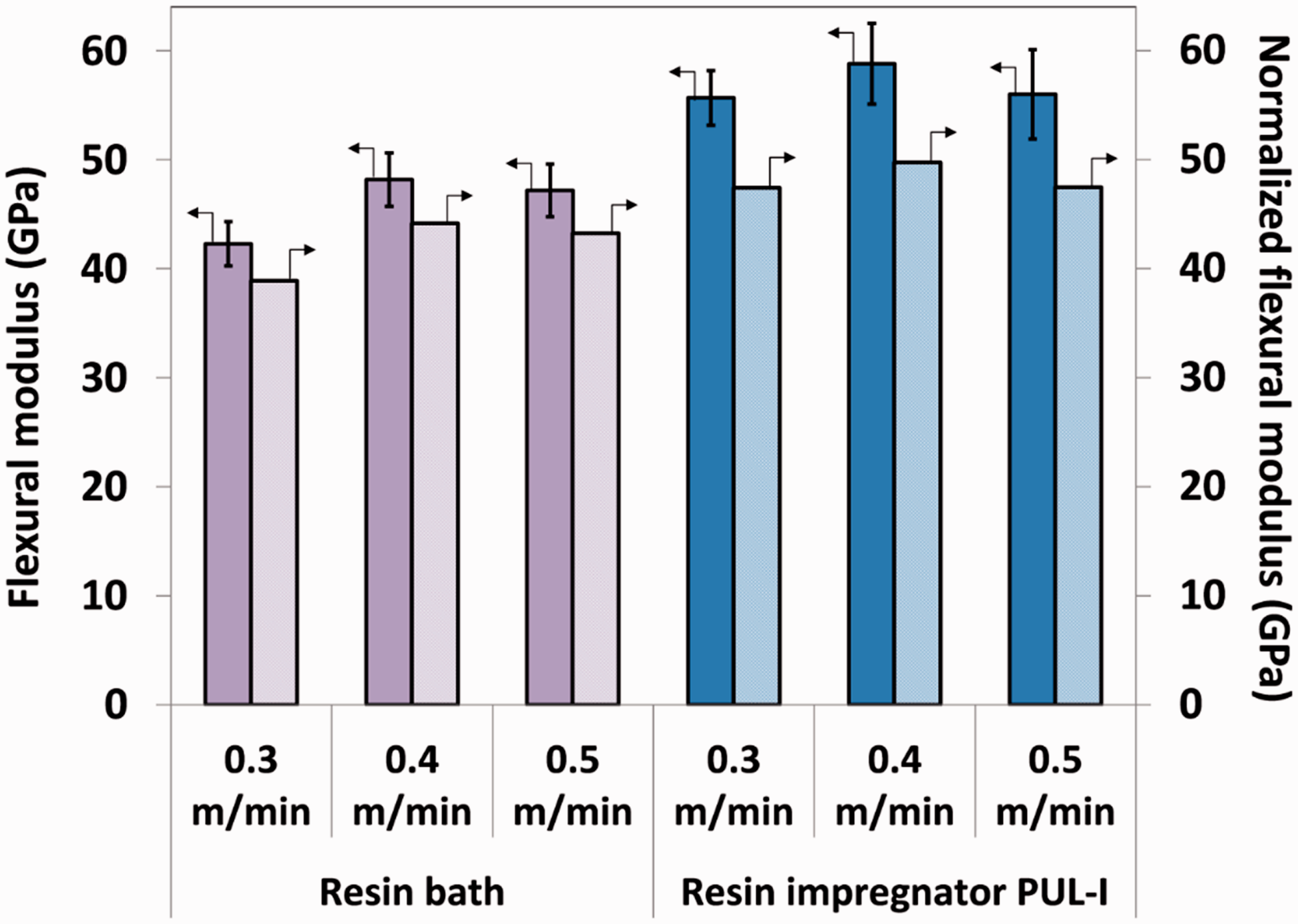
Another interesting feature to note is that the properties show an increasing trend with pultrusion speed. This may be related to the increase in the tension in the rovings at higher pultrusion speeds leading to improved orientation of the rovings. However, it should be noted that if the pultrusion speed is increased further, the resin will not cure completely. The normalised ILSS values (Figure 16) are all within the same range as these are generally considered a matrix dependent property.
ILSS for the pultruded epoxy/E-glass composites produced at three pultrusion speeds.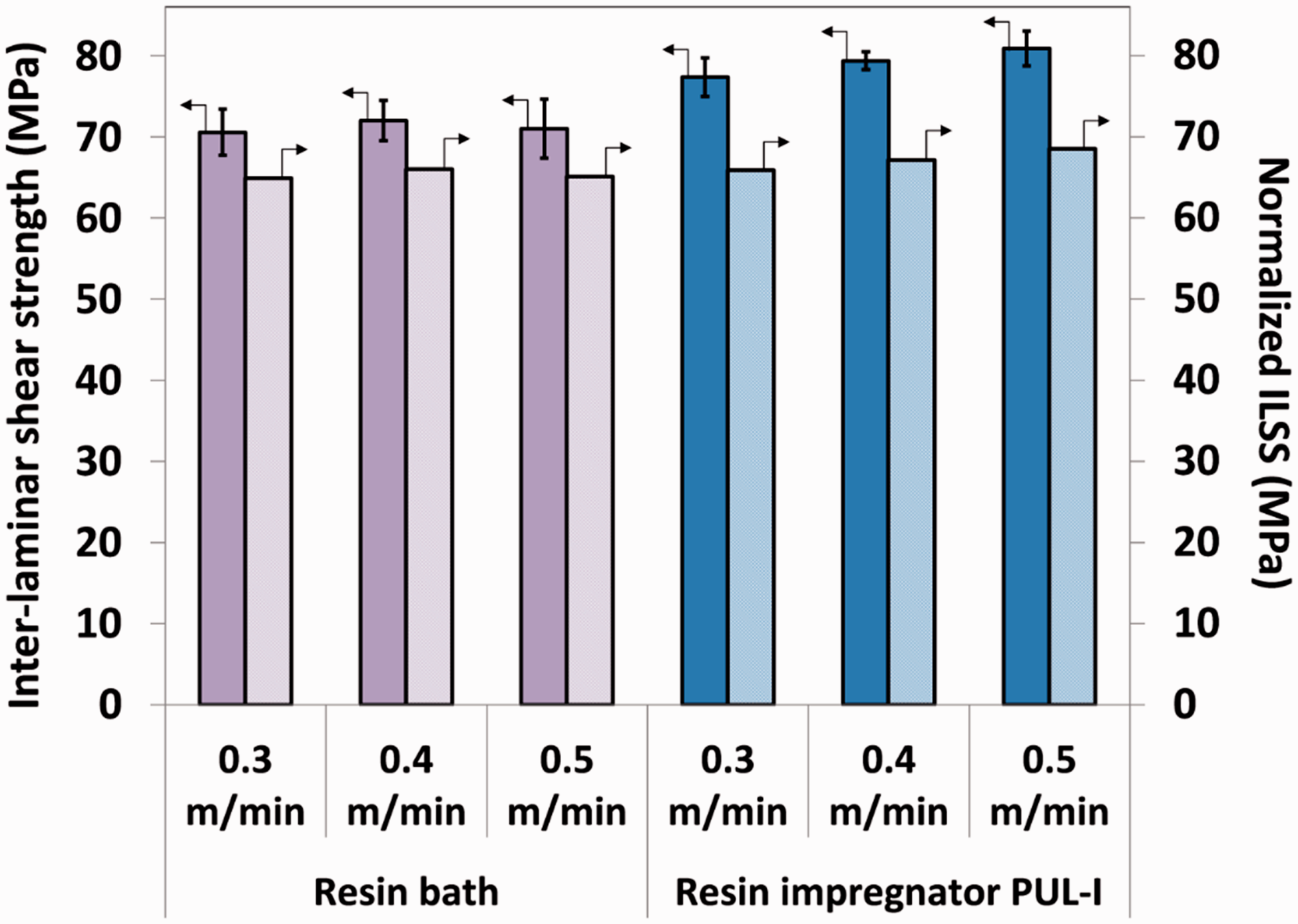
The Tg for the epoxy resin system (Araldite® LY556/Aradur® 917/ Hardener DY 070) from the manufacturer’s data,
20
determined by DSC, is reported to be in the range 140℃ to 155℃. The average Tg for epoxy LY556 resin measured using DSC in this study was 143.9 ± 2.1℃. This correlates well with the data generated in this study as shown in Figures 17 and 18, respectively.
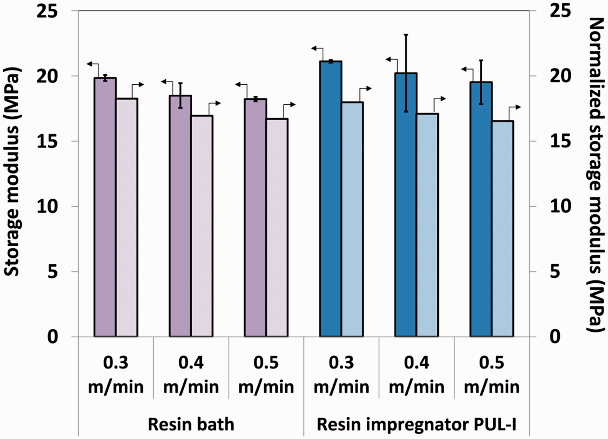
Glass transition temperatures via DMTA for the pultruded epoxy/E-glass composites produced at three pultrusion speeds. The data for the neat resin are also included. Storage moduli measured via DMTA for the pultruded epoxy/E-glass composites produced at three pultrusion speeds.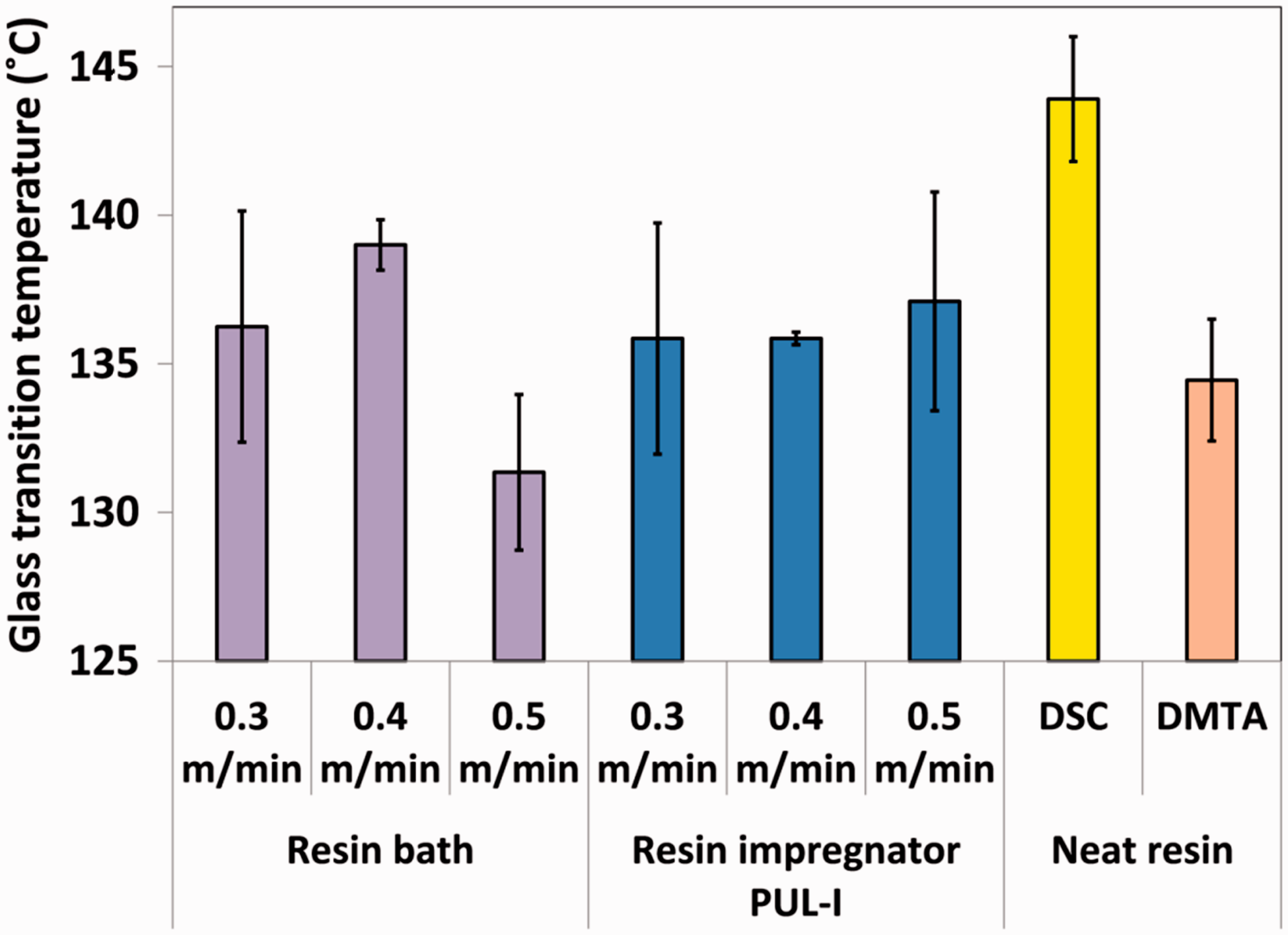
The glass transition temperature (Tg) of the pultruded composites was also determined from the peak of the loss tangent (tan δ). 21 It is clear from Figure 17 that the Tg for the modified and conventional pultruded composites are in the same range 135.8℃–138.8℃. Although the DSC and DMTA data are not expected to provide identical data, 21 the large discrepancy between the DSC and DMTA Tg data for the neat resins warrants further research.
The storage modulus (E′) data for the pultruded epoxy/E-glass composites are shown in Figure 18. Here, the storage moduli for the composites produced via the conventional and modified pultrusion techniques are similar. The normalised data (60% Vf) for the storage moduli are also cross-plotted in Figure 18.
Summary of selected papers to enable a comparison of the properties of the unidirectional epoxy /E-glass composites.
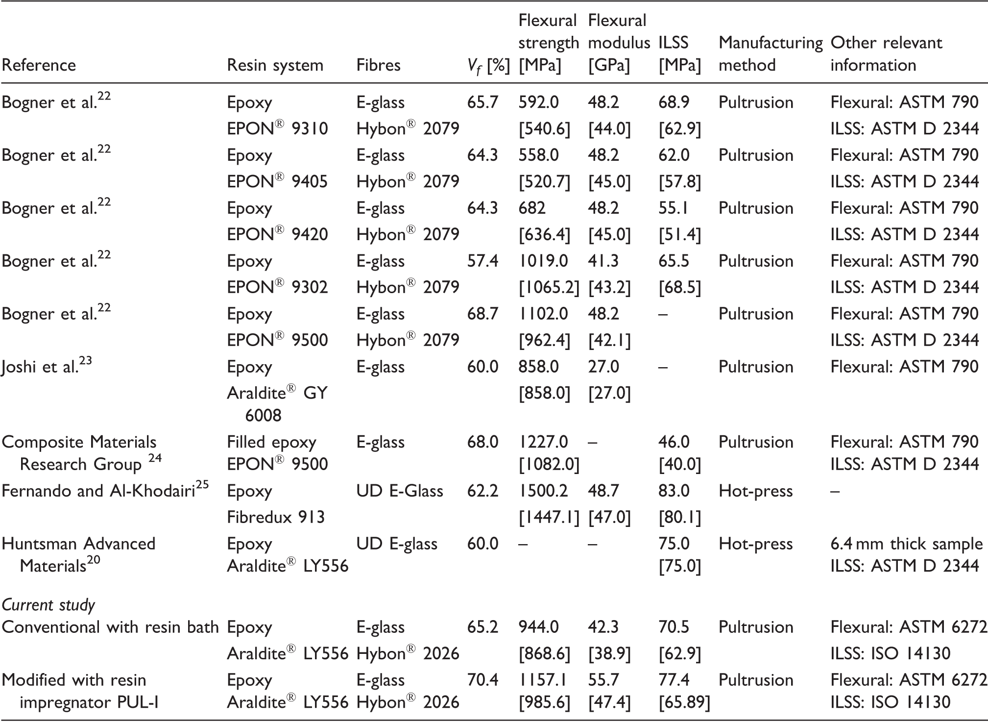
Note: The data in square brackets represent normalisation at 60% fibre volume fraction.
Waste resin generated and solvent consumption
The waste resin remaining in the resin impregnation unit at the end of production is usually transferred to a disposable container and cross-linked to a solid prior to disposal. One obvious advantage of the modified pultrusion process over the conventional technique involving the resin bath is the reduction in the volume of the waste resin that is generated at the end of production. This is primarily due to the relatively small dimensions of the impregnation unit. As a consequence of the compactness of the impregnator, the volume of solvent that was required for cleaning the equipment was also reduced significantly.
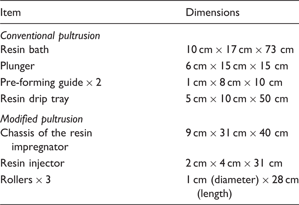
The actual volumes of the residual waste resin and solvent consumed are shown in Figure 19 where it can be seen that the modified pultrusion method resulted in more than a 90% reduction in the mass of mixed waste resin and solvent consumed. The data were collected when the pultrusion trials were undertaken using a 5 kg resin bath and resin impregnator PUL-I. The details of the items that required cleaning at the end of the experiment for the conventional and modified pultrusion techniques are listed in Table 7.
Reduction in the amount of mixed waste resin and cleaning solvent for the conventional and modified pultrusion techniques. A summary of the items that required cleaning for the modified and conventional pultrusion techniques.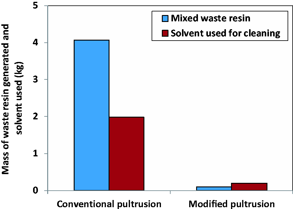
Conclusions
A modified pultrusion process was demonstrated where the dip-type resin bath system used in the conventional pultrusion process was replaced by a custom-built resin impregnator. The rovings were spread via a fibre spreading rig, prior to resin impregnation, to enhance the through-thickness impregnation. The system was designed to handle two resin delivery systems: a pressure-pot containing pre-mixed resin and an on-demand resin and hardener delivery system.
A DSC was used to define the die temperature and pultrusion speeds. A methodology was developed to estimate the impregnation efficiency of the resin impregnators in terms of a dimensionless impregnation number (Iimp). Here, the different modes of impregnation occurring within the resin impregnation unit were considered including, resin-injection, pin-impregnation, capillary action and compaction.
The pultrusion experiments were conducted at 0.3 m/min, 0.4 m/min and 0.5 m/min using a commercial pultrusion machine. The physical, mechanical and thermo-mechanical properties of composites produced using the conventional resin bath and modified pultrusion methods were compared. It was found that the composites produced via the modified pultrusion technique had marginally better mechanical properties when compared to those manufactured using the conventional resin bath method. However, the environmental benefits of the modified pultrusion technique are significant with regard to reduced solvent consumption for cleaning the equipment at the end of production. The volume of waste resin generated is also considerably lower in the modified pultrusion technique.
Footnotes
Acknowledgments
The authors wish to acknowledge the technical assistance provided by Professor Brian Ralph, Frank Biddlestone, D Harris, R Mahendran and L Wang.
Declaration of Conflicting Interests
The author(s) declared no potential conflicts of interest with respect to the research, authorship, and/or publication of this article.
Funding
The author(s) disclosed receipt of the following financial support for the research, authorship, and/or publication of this article: The authors wish to acknowledge financial support from the EPSRC (TS/G000387/1) and the Technology Strategy Board, Project AB134K and BD072K. The support given by the industrial partners (Pultrex, PPG, CTM, and Huntsman Polyurethanes) is duly acknowledged.