
Abstract
To address the safety risks posed by surface defects such as white edges, cracks, and black streaks that frequently occur during the injection molding of CATL CTP structural supports, as well as the low efficiency and high miss rate of traditional manual visual inspection, a dual-camera online detection system based on Fourier transform and multi-feature fusion is proposed. The system employs a rotary turntable to achieve multi-station coordinated operation and uses vertically arranged dual cameras to synchronously acquire images of the front and back surfaces of the supports. A detection strategy that fuses frequency-domain and spatial-domain features is adopted: in the frequency-domain stage, global frequency features are extracted using the Fast Fourier Transform (FFT), and defect information is enhanced through Gaussian filtering and inverse transformation; in the spatial-domain stage, shape and grayscale features are combined with threshold segmentation and morphological analysis to achieve the classification and recognition of micro-defects such as black streaks and white edges. The system adopts a multi-threaded asynchronous processing architecture, enabling parallel execution of image acquisition and algorithm processing through an interleaved memory read–write mechanism, reducing the single-part inspection cycle to 1.2 s. Experimental results show that, for 4000 tested samples, the recognition accuracy for both black streak and white edge defects reaches 98.4%–98.9%, with a minimum detectable defect size of 7 mm. By integrating a PLC-controlled pneumatic sorting device, the proposed system realizes online double-sided defect detection and automatic rejection of injection-molded parts, providing an innovative solution for surface quality inspection of high-precision structural components.
Keywords
Introduction
Research background
With the rapid development of intelligent manufacturing and Industry 4.0, surface quality control of precision components has become a critical factor in ensuring product performance and reliability. As an important structural component of battery modules, the CTP (Cell to Pack) support may exhibit micro-defects such as scratches and dents on its surface, which not only affect appearance but may also lead to structural failure due to stress concentration, thereby posing serious safety risks. Therefore, achieving efficient and high-precision automated detection of surface defects in CTP supports is of great industrial significance.
Early surface defect inspection mainly relied on manual visual inspection, which suffers from low efficiency, strong subjectivity, and operator fatigue. To overcome these limitations, traditional machine vision-based methods have been widely studied. Bhandarkar et al. 1 pointed out that conventional algorithms such as threshold segmentation, edge detection, and texture analysis can extract obvious defects under specific lighting conditions. However, such methods are highly sensitive to variations in illumination and are difficult to adapt to weak defect detection in complex backgrounds, resulting in limited robustness.
In recent years, deep learning technologies represented by convolutional neural networks (CNNs) have achieved breakthrough progress in industrial visual inspection. Compared with traditional methods, deep learning can automatically learn high-level semantic features from images, significantly improving detection accuracy. Ibrahim and Tapamo 2 summarized in a recent review that deep learning-based vision methods have become the mainstream approach for surface defect detection in industries such as steel and automotive manufacturing. In particular, one-stage object detection algorithms represented by the YOLO (You Only Look Once) series have attracted considerable attention due to their excellent real-time performance. For example, Han et al. 3 proposed the BED-YOLO model in 2024, which significantly improved real-time detection accuracy for micro-defects on bearing surfaces by introducing enhanced feature pyramids and attention mechanisms. Zheng et al. 4 proposed a multi-channel fusion-based MD-YOLO model, effectively addressing missed detections caused by background interference in complex industrial environments. In addition, to cope with data scarcity in industrial scenarios, Yan et al. 5 investigated small-sample-learning-based nondestructive testing methods, demonstrating the great potential of deep learning in precision quality control.
Despite the remarkable achievements of spatial-domain deep learning methods, several challenges remain. First, for extremely small scratches or low-contrast defects on the surface of CTP supports, relying solely on spatial-domain features often makes it difficult to distinguish defects from background textures, leading to insufficient detection sensitivity. To address this issue, researchers have begun to explore the application of frequency-domain analysis in defect detection. Frequency-domain transformations (such as the Fast Fourier Transform, FFT) can convert images into the frequency domain, where periodic background textures are concentrated in low-frequency or specific frequency components, while abrupt defect signals are distributed in high-frequency regions, making them easier to separate. Second, most existing detection systems adopt a single-camera viewpoint, which is prone to blind areas caused by surface reflections or geometric occlusions. Recent research trends indicate that multi-view information fusion is an effective solution to this problem. According to a study published in *Sensors* in 2025, multiview artificial intelligence fusion methods significantly improve the detection rate of fine scratches on metal surfaces and enhance system robustness compared with single-view solutions. 6 However, existing multi-view or frequency-domain combined methods often involve high computational complexity. How to achieve production-line-level real-time detection with high accuracy using a multi-threaded asynchronous architecture remains a key challenge.
To address the above issues, this paper proposes a surface defect detection system for CTP supports based on synchronized dual-camera acquisition and frequency-spatial domain feature fusion. A dual-camera synchronous acquisition and multi-threaded asynchronous processing framework is designed to effectively overcome single-view occlusion problems while significantly improving real-time online inspection performance. In addition, an innovative frequency-spatial feature fusion strategy is proposed, in which FFT is used to extract salient frequency-domain features of images and fuse them with spatial-domain features, substantially enhancing the representation capability for micro-defects.
Technical approach
The system adopts a dual-feature fusion framework, combining frequency-domain features 7 and spatial-domain features 8 for defect detection, and is equipped with a corresponding hardware system to realize automatic rejection.
In the frequency-domain analysis stage, the acquired images are transformed into the frequency domain using FFT for analysis. Convolution operations are then applied to filter out irrelevant fundamental features. Afterward, inverse transformation is performed to convert the images back to the spatial domain, and a subtraction operation with the original image is conducted to highlight defect features.
In the spatial-domain feature stage, shape and grayscale features are integrated to perform defect detection on the images with enhanced defect features, enabling defect classification.
The hardware system integrates a rotary turntable, dual cameras, and a multi-light-source illumination system, and employs multi-threaded processing technology to ensure real-time performance and robustness.
System design
To address the challenges faced by existing defect detection systems in double-sided workpiece inspection—including single-view blind spots and the difficulty of balancing high-precision algorithms with production-line real-time requirements—this study designs an online detection system that integrates synchronized acquisition, frequency-domain enhancement algorithms, and a software–hardware co-designed pipeline.
The key innovation of the proposed system lies in the adoption of an encoder-triggered dual-camera hardware architecture with sub-millisecond synchronization, which fundamentally resolves the spatiotemporal alignment problem in double-sided inspection and ensures complete coverage without viewpoint omission. In addition, a “frequency-domain differential enhancement” algorithmic strategy is proposed, in which a background model is constructed and suppressed in the frequency domain using Fourier transform 9 and Gaussian filtering, 10 followed by a differential operation to significantly enhance the signal-to-noise ratio of defect features. This approach effectively overcomes the sensitivity of traditional methods to illumination variations and the limited generalization capability of deep learning methods under small-sample conditions.
Furthermore, a multi-threaded asynchronous processing framework based on interleaved memory read–write operations is established, enabling pipeline execution of image acquisition, algorithm processing, and sorting operations. As a result, stable and efficient real-time detection performance is achieved under constrained computational resources. The following sections will elaborate in detail on the system hardware architecture, algorithmic workflow, and real-time performance assurance mechanisms.
Hardware system design
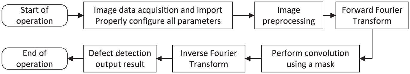
The production workflow of the proposed detection system is as follows. When a product enters the inspection system, a trigger sensor generates a signal, upon which the host computer controls the cameras to acquire images of both the front and back surfaces of the product. After image acquisition, multi-threaded algorithms are employed to process the images and output the inspection results. Based on these results, the system performs product sorting accordingly. The detailed operational workflow of the system is illustrated in Figure 111,12 and the hardware system design is shown in Figure 2.
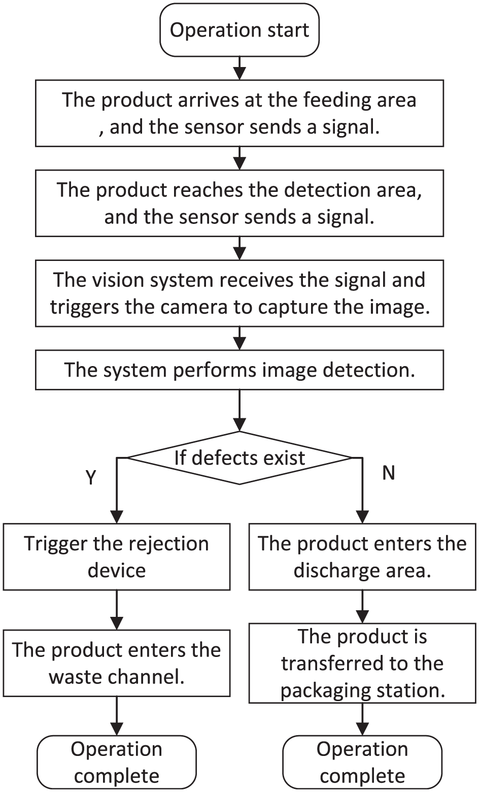
System workflow.
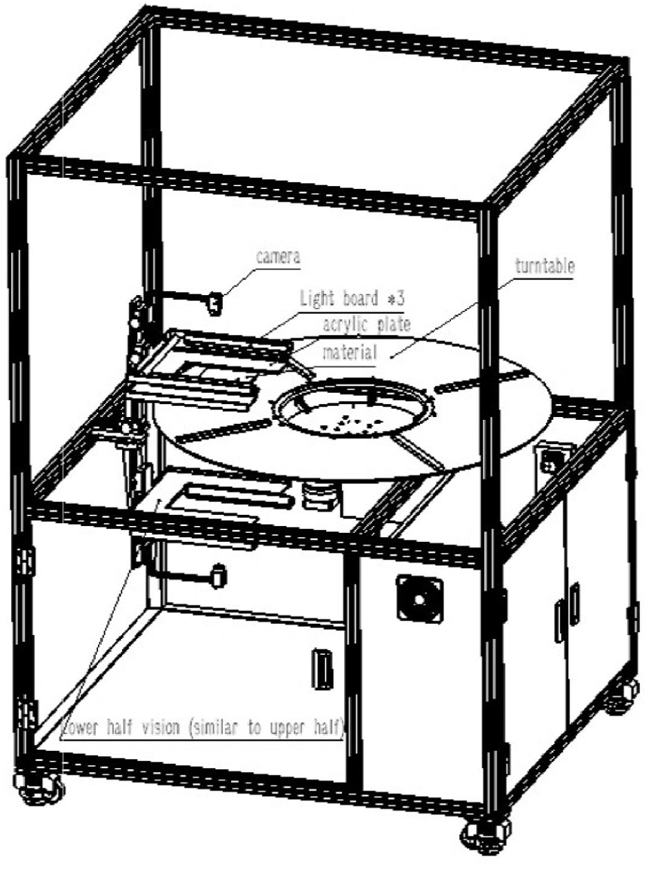
Overall hardware design of the device.
Configuration of rotary turntable detection mechanism
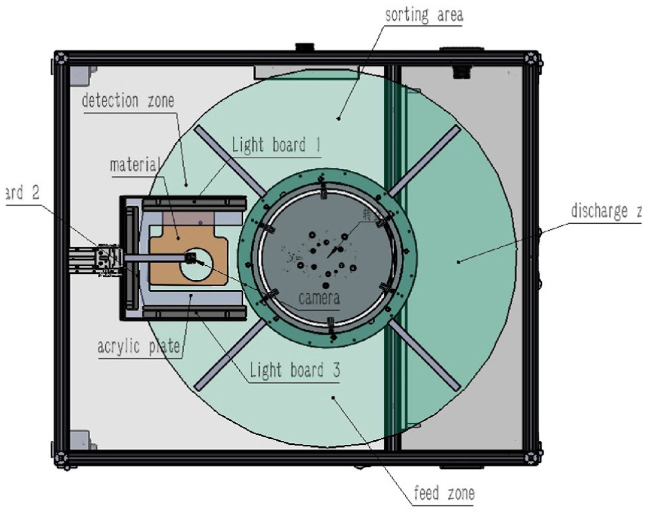
The system adopts a rotary turntable (1.2 m in diameter, four stations) to realize multi-station cooperative inspection and sorting. The turntable is divided into four functional zones, and rotation is used to synchronously complete feeding, inspection, sorting, and discharge operations. The structural design of the turntable mechanism is shown in Figure 3, and the corresponding workflow is illustrated in Figure 4.
Design of turntable mechanism.
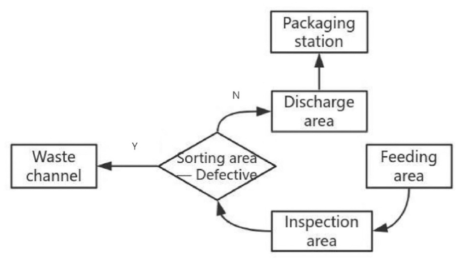
Turntable workflow.
Feeding Zone: A gantry places injection-molded supports onto the turntable feeding zone. A photoelectric sensor below the feeding zone detects the support’s entry. Upon detection, it triggers turntable rotation to move the support into the detection zone.
Detection Zone: When the support rotates to the center of the detection zone, the upper and lower cameras synchronously capture front and back side images. Multi-threaded image processing simultaneously performs defect detection on both sides to ensure efficiency. After detection, the results are sent to the lower-level controller, triggering turntable rotation. If a defect is found, the turntable rotates to the sorting zone for rejection. If the result is normal, it rotates directly to the discharge zone.
Sorting Zone: Based on the detection result, a signal is sent to the PLC. The PLC controls the corresponding rejection robotic arm to move to the sorting zone and remove the defective part. After removal, it triggers motor rotation and activates the next solenoid valve. A pneumatic pusher moves the defective part into the waste channel, achieving rejection.
Discharge Zone: Qualified products are output via a conveyor belt to the packaging station. The conveyor belt speed is synchronized with the turntable to prevent accumulation or collision.
Light source and image acquisition system design
The CTP structural support is a double-sided component. To simultaneously acquire image information from both surfaces without mutual interference, the illumination and image acquisition system is specially designed. High-transmittance tempered glass is used as the bottom plate, allowing the cameras to capture images of both the upper and lower surfaces at the same time. The overall image acquisition system is shown in Figure 5.
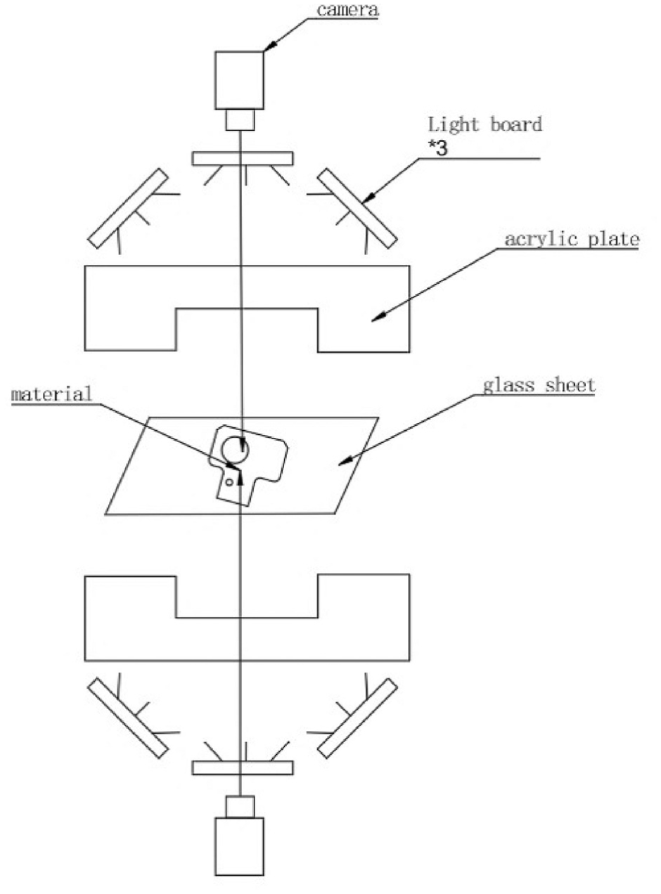
Schematic diagram of image acquisition system.
In terms of the illumination system, due to the large size and smooth surface of the part, conventional lighting methods are insufficient for effective surface feature extraction. Therefore, different illumination schemes were comparatively evaluated. The experimental setups are shown in Figure 6, and the corresponding experimental results are summarized in Table 1. The results indicate that Scheme 4 achieves the best performance. In this scheme, three linear light sources are arranged to illuminate the surface at a low angle, which effectively suppresses specular reflection and provides uniform illumination compensation. For the back surface of the part, image acquisition must be performed through the glass substrate. Since glass exhibits high reflectivity, low-angle diffuse illumination is adopted for the bottom lighting. A soft white acrylic diffuser plate is superimposed on the light source to ensure uniform light transmission through the glass and to avoid interference caused by specular reflections. 13
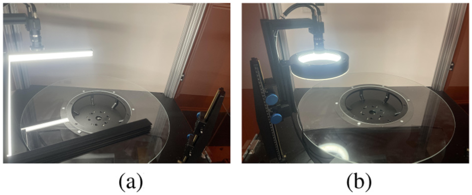
Lighting experimental test image: (a) bar light and (b) ring light.
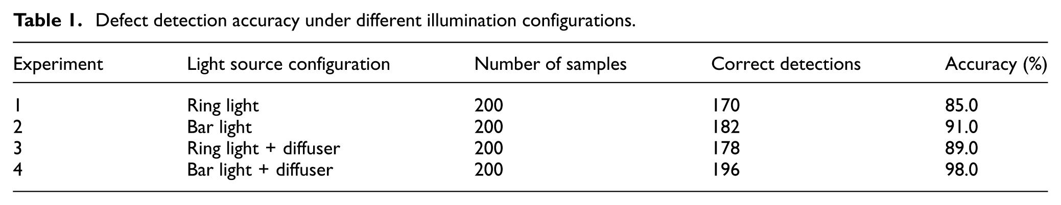
Defect detection accuracy under different illumination configurations.
Regarding camera selection, the CTP structural support has relatively large geometric dimensions of approximately 230 mm × 220 mm. To ensure the acquisition of clear and complete images, a Basler ace acA2440-155uc industrial camera (2448 pixels × 2048 pixels, 155 fps) is employed and vertically aligned with the inspection area. A lens with a focal length of 12 mm is used, with a working distance of 350 mm. The camera operates in external trigger mode and is synchronized with the turntable via encoder–PLC linkage, ensuring that image acquisition is triggered when the turntable rotates to the inspection position, with a synchronization error of less than 0.1°. The encoder resolution is 1024 pulses per revolution, and together with a PID control algorithm, stable turntable rotation speed is achieved.
Algorithm design and implementation
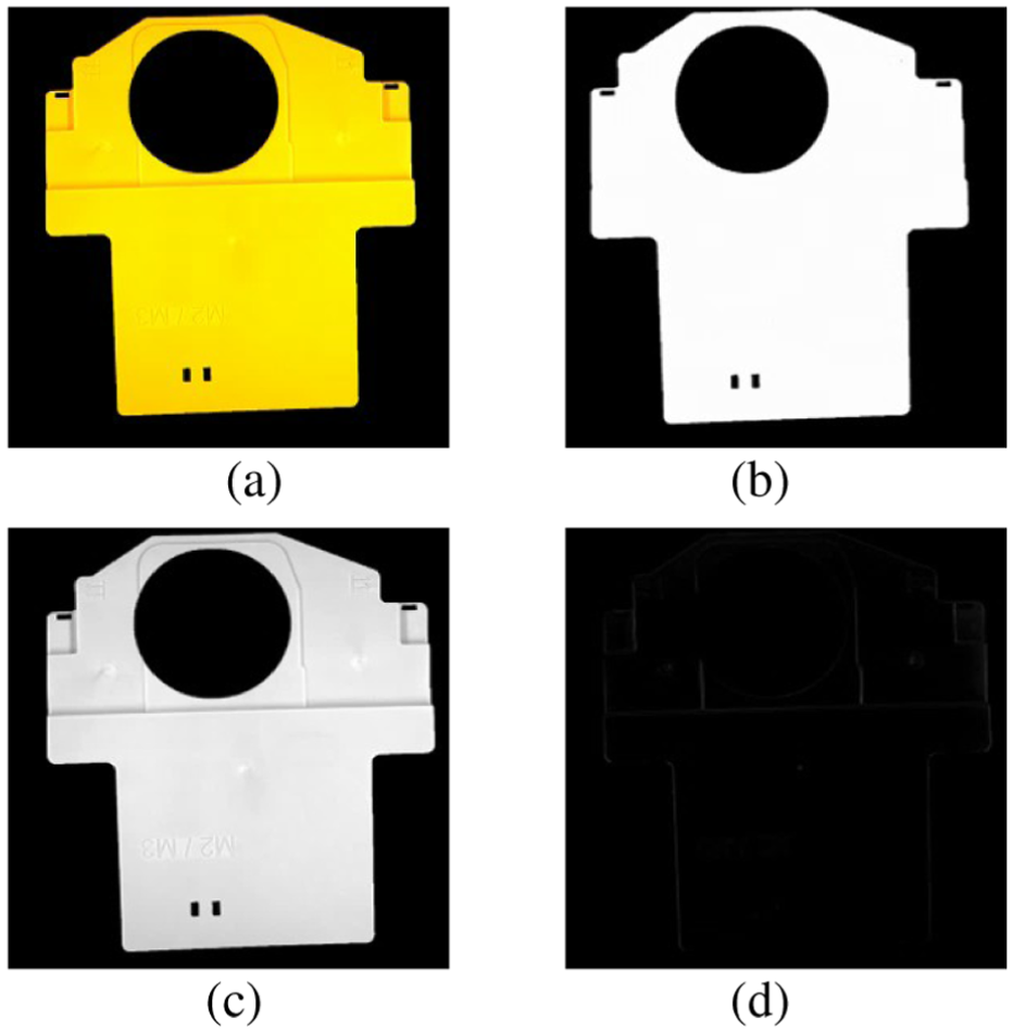
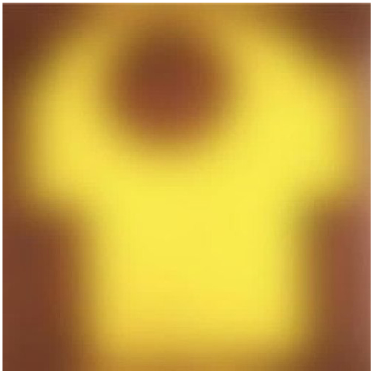
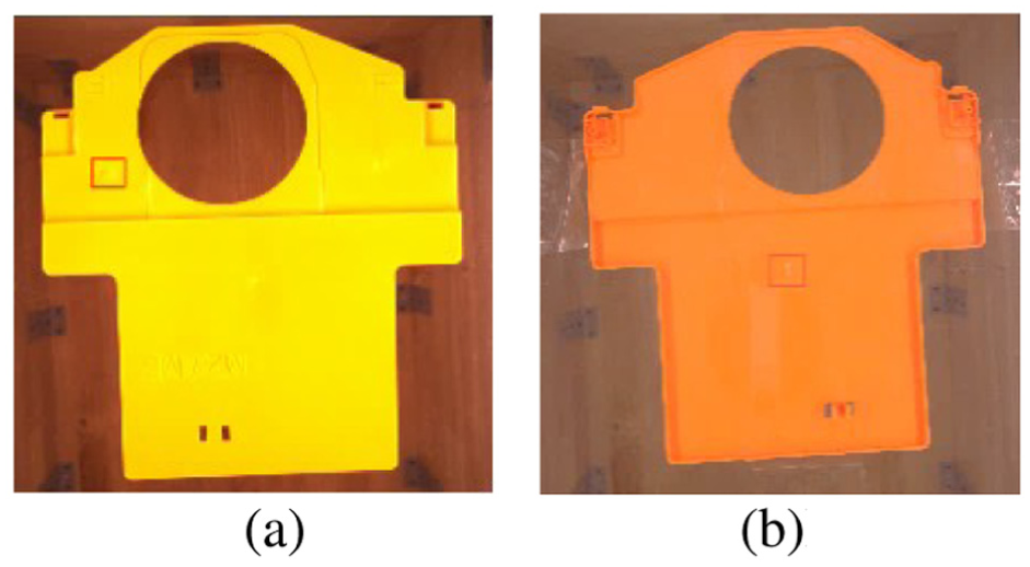
As an injection-molded component, the CTP structural support, as shown in Figure 7, mainly exhibits two types of defects, namely black streaks and white edges. The inspection is performed on both the front and back surfaces.
Front and back drawings of parts: (a) front side and (b) back side.
Due to the large size of the CTP component and the subtle nature of its defects, traditional feature extraction methods struggle to achieve effective detection. In this study, a defect identification approach that combines frequency-domain and spatial-domain information is adopted. The overall processing workflow is illustrated in Figure 8. After image acquisition, preprocessing is first performed, followed by transformation of the image into the frequency domain, where filters are applied to suppress background features. The processed image is then transformed back into the spatial domain via inverse transformation and subtracted from the original image to highlight defect information. Finally, classification and detection are achieved through multi-feature fusion.
Algorithm detection workflow.
Since defective features of the component are mainly characterized by color attributes, and a part is considered defective if either the front or back surface contains defects, feature detection must be performed separately on both surfaces. The obtained inspection information forms data sets A and B, respectively. The detection results are then combined using a logical OR operation to generate data set C, which represents the rejection decision and is transmitted to the lower-level industrial control computer to complete the removal process. The feature recognition workflow is shown in Figure 9.
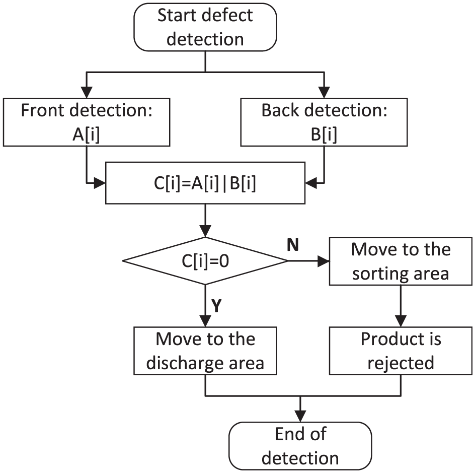
Defect detection process.
Image preprocessing
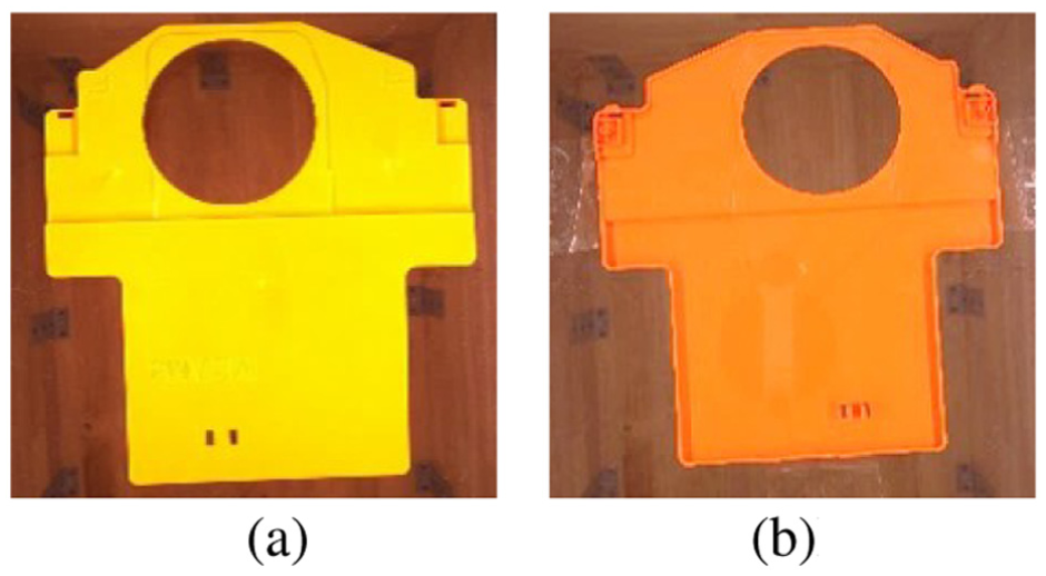
In this study, the acquired images are subjected to RGB channel separation and converted into grayscale images to facilitate feature recognition. The CTP structural support is orange in color, and under the G channel, the color differences between black streaks and white edges are more distinct. In contrast, the R and B channels exhibit poorer discrimination of the color features of these two defect types. Therefore, the G component is selected for image processing to extract grayscale features, as shown in Figure 10.
Comparison of original image and RGB component image: (a) original image, (b) R-channel image, (c) G-channel image, and (d) B-channel image.
After extracting the image in the G channel, histogram equalization is applied to enhance the contrast between defect features and the background of the part. This is combined with an averaging filter to preserve edge details, providing a refined image for subsequent processing.
Defect detection algorithm based on FFT
In images with conventional pixel distributions, information such as edges, textures, noise, and fine details is often difficult to extract, 14 as these high-frequency components are hard to distinguish. However, by applying the Fourier transform, the image can be converted from the spatial domain to the frequency domain, revealing the hidden global frequency information and enabling more efficient defect detection. This analytical capability makes the Fourier transform particularly advantageous for detecting periodic defects or uniformly distributed anomalies. 15
Therefore, for CTP structural brackets, which are relatively large in size and possess small, subtle defects, it is appropriate to apply the FFT (Fast Fourier Transform) algorithm to convert the captured images into the frequency domain for processing.
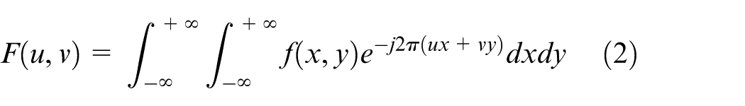
Fourier transform formula
The transformation of an image into the frequency domain is typically accomplished using the Fourier transform. However, the conventional discrete Fourier transform (DFT) requires a long computation time, which cannot meet the efficiency demands of rapid screening in automated production. 16 Therefore, this study employs the FFT (Fast Fourier Transform) algorithm to convert images into the frequency domain. This method is an improved version of the traditional discrete Fourier transform, offering significantly higher computational speed and efficiency. 17
Images are stored in computers as discrete pixel matrices, so the continuous Fourier transform must be adapted for discrete scenarios. The core idea of the continuous Fourier transform is to decompose a time-domain signal into sinusoidal and cosinusoidal components of different frequencies, with its forward transform formula given by:
Here,
For a two-dimensional image, the continuous signal is extended to a two-dimensional function
Here,
In the discrete image scenario, the image size is
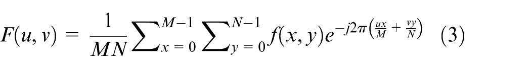
where
However, the computational complexity of the traditional DFT is
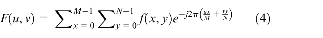
where
The experiments were conducted on TCP plastic structural brackets with surface defects to obtain the corresponding variation images. Due to the large size of the parts and the small scale of the defects, the images contain complex features, and non-defective elements can interfere with defect detection. Therefore, the images were transformed from the spatial domain to the frequency domain using the Fast Fourier Transform (FFT) to suppress interfering features and enhance the defect signals. The resulting frequency-domain representation is shown in Figure 11.

Fourier-transformed frequency-domain image.
Convolution calculation of frequency domain image
The image is transformed into the frequency domain using the Fourier transform. To highlight specific target information, a filter of a designated size is applied to suppress irrelevant features. Through experimentation, a Gaussian filter was employed for this purpose in the project.
The operation of the Gaussian filter starts with constructing a pixel kernel of a specific size, which is used to scan the image. For each scanned region, the center pixel is replaced by the weighted average of all pixels within the kernel, where the center pixel value is determined by itself and the neighboring pixels through weighted averaging. The two-dimensional Gaussian distribution function is given in: 18
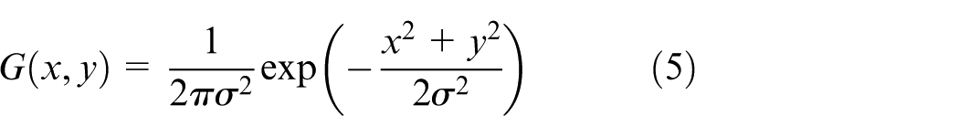
Here,

Frequency-domain image after convolution.
Multi-feature fusion
The convolution-processed image is inversely transformed back to the spatial domain for subsequent processing, as shown in Figure 13.
Frequency domain image after convolution processing.
Based on the inversely transformed image, a subtraction operation is performed with the original image to obtain a feature image with most of the irrelevant information removed for subsequent image feature detection, as shown in Figure 14.
Subtract operation result.
Multi-feature fusion
Using a multi-feature extraction method, the image with enhanced features obtained after processing with the FFT algorithm is further analyzed to achieve final defect extraction, thereby determining whether it meets the abnormality criteria.
An adaptive thresholding method is used to determine the segmentation threshold

where
Erosion operation is applied to remove small noise points, using a

Dilation operation is applied to restore the complete shape of the defect region:

Area feature:
Gray-level mean feature:
Classification rule: When
Use the algorithm to obtain the grayscale values of pixels in the image and determine factors such as the range of grayscale values. On this basis, perform morphological operations, threshold segmentation, and shape selection to distinguish defect regions, thereby achieving detection. Based on the above operations, obtain the result regions for both the front and back sides of the part, and highlight these regions on the original image. The detection results are shown in Figure 15.
Defect detection result: (a) front side and (b) back side.
Multi-threaded algorithm
Since the system needs to simultaneously capture images of both sides of the part and filter multiple defect features, it places high demands on real-time performance. This system uses multithreading to meet the real-time requirements of image acquisition and processing. A recursive memory access method is employed: during program execution, a certain amount of memory is first allocated to store data, and by exploiting time differences, the acquisition and processing threads access memory in an interleaved manner to read and write data, achieving real-time processing. 19
The algorithm primarily adopts synchronous acquisition and asynchronous processing. Cameras 1 and 2 simultaneously capture the front and back images of the part. The data are stored in memory, and processing threads are invoked with a time offset to handle the data.
The specific programing method is as follows: first,
This method leverages the time difference between acquisition and processing threads to manage system memory data, as illustrated in Figure 16.
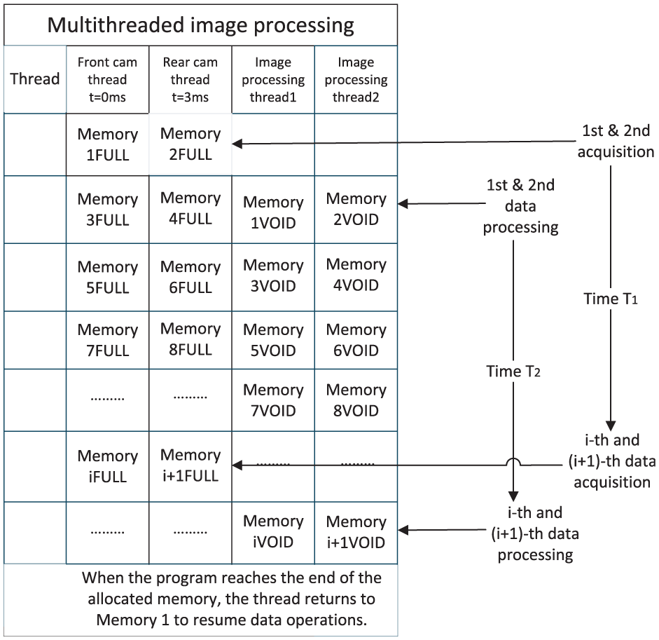
Multi-threaded method diagram.
Comparison between existing algorithms and the proposed method in this paper
The existing mainstream surface defect detection methods can be mainly divided into traditional image processing techniques, such as threshold segmentation 21 and edge detection, 22 and deep learning-based detection methods. 23
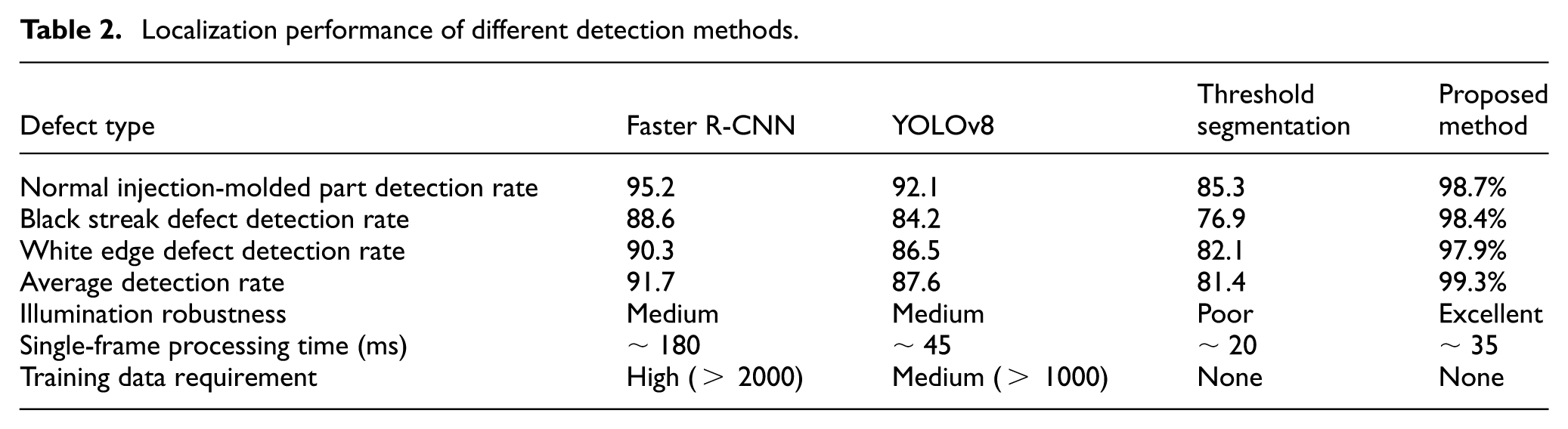
Although traditional methods can achieve pixel-level precise localization, they rely on stable imaging conditions; deep learning methods, while possessing strong feature-learning capability, may suffer from poor generalization and low detection confidence for tiny defects when trained on limited samples. In this study, a comparative experiment was conducted on 4000 samples, as shown in Table 2. Traditional methods exhibited high false detection rates under illumination variations, whereas deep learning models trained with small datasets still showed insufficient detection ability for minute defects, highlighting the limitations of existing methods in real industrial scenarios. The detection results are shown in Figure 17.
Localization performance of different detection methods.
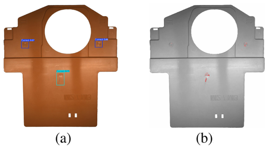
Results of traditional image processing methods and deep learning methods: (a) YOLOv8 and (b) threshold segmentation.
Algorithm innovation
A differential enhancement method for defect detection is proposed. The method transforms images into the frequency domain using FFT, selectively suppresses specific frequency components representing background periodic textures through a Gaussian filter, and then performs an inverse transform followed by differencing with the original image. This strategy actively removes the background, significantly enhancing the signal-to-noise ratio of defect regions and overcoming the insensitivity of traditional methods to low-contrast defects. Compared with deep learning models such as YOLO that rely on large-scale training data and may suffer from generalization issues, this method achieves higher detection accuracy under the same conditions. Moreover, unlike traditional machine vision approaches that are highly sensitive to lighting conditions, this method reduces dependence on illumination through frequency-domain differencing, demonstrating superior environmental adaptability and robustness.
Experiment and result analysis
Experimental platform and deployment feasibility
A simulated platform was constructed for software testing to detect and sort the critical surface defects of black streaks and white edges on products. The experimental environment consisted of a Windows 11 operating system, an Intel Core i9-13900HX processor, 32 GB of RAM, and an NVIDIA RTX 4090 GPU with 16 GB of VRAM. The experimental platform is shown in Figure 18.
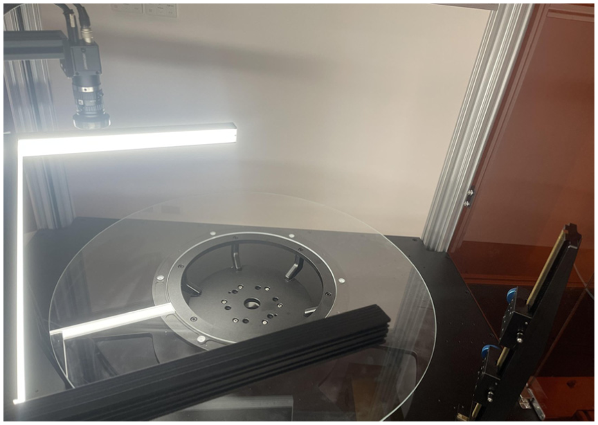
Experimental platform.
Taking deployment under different environments as an example, this system can be implemented at the end of an existing legacy injection molding production line. If the original line is equipped only with a basic conveyor belt, the proposed solution requires just three incremental deployments: installing a dual-light camera module for top-and-bottom imaging in the conveyor inspection section, integrating a simple pneumatic ejection device controlled by a PLC in the sorting section, and deploying the defect detection algorithm program on the host computer.
The system communicates with the original line PLC via standard I/O interfaces without the need to reconstruct the existing production line control system. During long-term operation, aside from initial equipment investment, maintenance is minimal: standard pneumatic cylinder seals need replacement every 6 months or 500,000 cycles (costing approximately $29 per replacement), and the carrier glass plates need replacement every 12–18 months due to normal wear (approximately $72 each). The annual hardware maintenance cost can thus be kept at a low level.
No modifications to the main production line structure are required, and key maintenance tasks can be performed by existing line personnel, achieving a truly “plug-and-play, low-cost, and sustainable operation” upgrade.
Results analysis
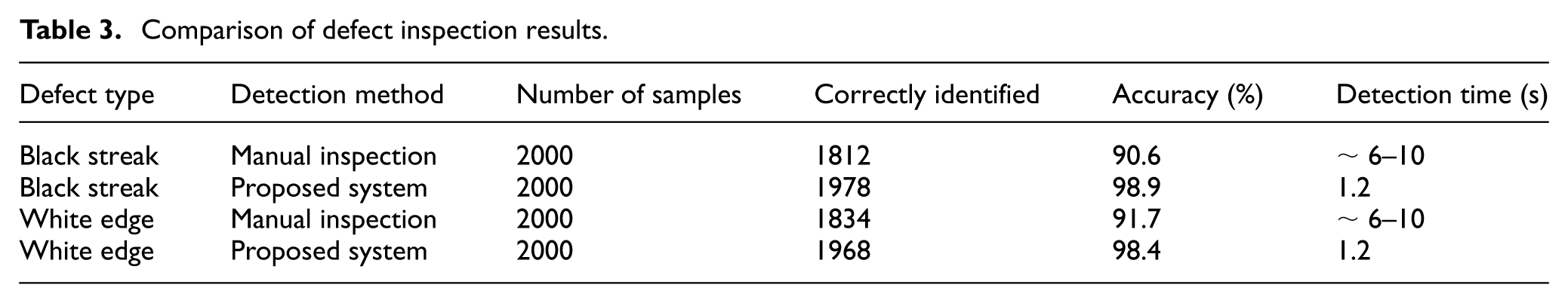
The black streak and white edge defects of 4000 CTP products were inspected using both traditional manual inspection and the proposed system. The testing showed that the sorting time per product was 1.2 s, and the recognition accuracy ranged from 98.4% to 98.9%, outperforming traditional manual inspection in both efficiency and accuracy. The test results are presented in Table 3.
Comparison of defect inspection results.
Conclusion
This study uses CTP structural supports as a test case to analyze the application of a machine vision system in automated surface quality inspection of plastic parts. A defect detection method is proposed that combines FFT-based frequency-domain and spatial-domain image transformation with Gaussian filtering, followed by differential operations to enhance image features, and further employs traditional multi-feature detection for defect screening. To ensure real-time performance, a multi-threaded approach for front and back cameras and image processing is implemented, using synchronous acquisition and asynchronous processing, combined with specially designed hardware, to enable efficient removal of defective parts. The hardware and software system was successfully developed and deployed to automatically inspect the surface quality of large CTP structural supports with subtle defects on an automated production line. Experimental results demonstrate that the system can detect black streaks and white edge defects on 4000 CTP parts, achieving a single-part sorting time of 1.2 s and an identification accuracy of 98.4%–98.9%, meeting industrial production requirements. This project provides a practical reference for front-and-back inspection of injection-molded parts.
Footnotes
Ethical considerations
This article does not contain any studies with human participants or animals performed by any of the authors.
Consent to participate
Informed consent was not required as this research did not involve any human participants.
Consent for publication
Not applicable, as this manuscript does not contain any individual person’s data in any form (including any individual details, images or videos).
Author contributions
JKW conceptualized the study, developed the methodology, and wrote the original draft. RXC conducted the experiments and curated the data. YJH assisted in formal analysis and validation. CCW supervised the project, acquired funding, and reviewed and edited the manuscript. All authors have read and agreed to the published version of the manuscript.
Funding
The authors received no financial support for the research, authorship, and/or publication of this article.
Declaration of conflicting interests
The authors declared no potential conflicts of interest with respect to the research, authorship, and/or publication of this article.
Data availability statement
Data sharing not applicable to this article as no datasets were generated or analyzed during the current study.