
Abstract
This paper presents the design, modeling, and real-time control of a recently developed Ball-on-T-shaped Inverted Pendulum (BTIP) system mounted on a motorized cart, serving as a novel experimental platform for advanced control validation. The nonlinear dynamics are derived using the Euler–Lagrange formulation and expressed in state-space form to facilitate controller design. Two model- based control strategies—pole placement and Linear Quadratic Regulator (LQR), including an extended LQR with integral action—are developed to stabilize the under-actuated and highly unstable system. A full-state observer is implemented to estimate unmeasured states and integrated into the closed-loop framework. The controllers are validated through MATLAB/Simulink simulations and real- time implementation using the Simulink Real-Time environment and National Instruments data acquisition (DAQ) hardware. Experimental results demonstrate that both control strategies successfully stabilize the BTIP system. The LQR controller achieved full stabilization within approximately 2.8 s, with a maximum pendulum deviation of ±0.015 rad and ball–position error below 5 cm, while maintaining the control effort within ±5 N. In comparison, the pole–placement state–feedback controller stabilized the system within about 3.2 s, with slightly higher noise and control effort. The BTIP platform thus provides a robust benchmark for evaluating advanced control algorithms in nonlinear, under-actuated systems and an effective educational tool for real-time control and mechatronics applications.
Keywords
Introduction
System control theory has gained significant attention in recent decades, with inverted pendulum systems emerging as a fundamental area of study due to their demonstration of inherently unstable dynamics. In the classic configuration of a single inverted pendulum mounted on a moving cart, the primary objective is to maintain the pendulum in its upright position by regulating the linear motion of the cart.1–4 This setup encapsulates explicitly unstable behavior, making it a well-established benchmark for evaluating control strategies. The system comprises a rigid multi-link structure attached to a mobile base (the cart), where the cart’s movement—induced by a time-varying force—serves as the control input to stabilize the pendulum in a vertical orientation.
A range of control methodologies has been applied to such systems, including fuzzy logic control,5,6 neural network-based control, 7 and conventional approaches like proportional integral derivative (PID) control. 8 This study focuses on the modeling, simulation, and control of a novel, highly dynamic nonlinear mechanism: a ball-on-T-shaped inverted pendulum (BTIP) mounted on a moving cart. The system’s mathematical model was developed using the Euler–Lagrange formulation, and two control strategies—pole placement and linear quadratic regulator (LQR)—were explored to govern its behavior.
This work is motivated by the educational and research significance of inverted pendulum systems, which are widely recognized as benchmark platforms for evaluating a broad range of control strategies, such as state feedback, optimal, nonlinear, and intelligent control methods. These systems allow for the analysis of key performance criteria—stabilization, trajectory tracking, disturbance rejection, and robustness—while also enabling the investigation of real-world constraints like sampling frequency and system delays. Additionally, the proposed BTIP system serves as an interactive platform for multidisciplinary experimentation, encompassing domains such as sensor integration, signal processing, system interfacing, embedded systems, and network communication. Altogether, the BTIP system represents a valuable educational and experimental resource for the university’s control engineering laboratory.9,10
Inverted pendulum systems are widely regarded as fundamental experimental frameworks in control theory due to their inherent instability and rich nonlinear dynamics. Boubaker and Iriarte 11 emphasized the role of such systems in developing robust self-oscillation strategies, introducing switched integral sliding mode control to maintain consistent oscillation despite external disturbances. Tamimi 12 modeled and controlled a twin-inverted pendulum on a moving cart using the Euler–Lagrange method and applied both LQR and nonlinear model predictive control (NMPC) techniques, showing their effectiveness through simulation under uncertainty. In a related study, Tamimi 4 compared PID, LQT, LMPC, and NMPC controllers for an inverted pendulum robot, concluding that NMPC offers superior performance by addressing nonlinear system dynamics directly. Sweiti and Tamimi 13 proposed a novel BTIP system, where modeling and control via pole placement and LQR successfully stabilized the complex structure. Haddad and Tamimi 14 conducted a comparative simulation and experimental study on the ball-and-plate system using several model-based controllers, demonstrating that systematic model-based tuning yields superior transient performance and disturbance rejection compared with heuristic approaches. This study, although applied to a different under-actuated mechanism, shares close similarities with the BTIP in its coupled translational–rotational dynamics and serves as a relevant reference for the present work. Lastly, Tahboub et al. 15 developed a flexible educational platform featuring a double inverted pendulum and demonstrated the practical applicability of LQR over fuzzy and predictive control in real-time environments. Collectively, these contributions provide a strong foundation for advancing the modeling and control of novel under-actuated systems like the one proposed in this work.
The inverted pendulum and its variants remain benchmark systems for studying stabilization and control of under-actuated and highly nonlinear dynamics. Their relevance extends from educational laboratories to real applications such as self-balancing vehicles, robotic manipulators, and walking robots, where maintaining an unstable equilibrium is essential. A wide range of control approaches has been explored, including classical PID, modern state feedback, optimal and robust schemes, and, more recently, fractional-order and intelligent control methods. Notably, Saleem et al. 16 introduced the Complex Fractional-Order LQIR (CFO-LQIR) controller and validated it experimentally on a rotary inverted-pendulum platform, showing improved transient behavior and robustness over conventional designs. These advances highlight the continuing importance of inverted-pendulum systems as practical testbeds for evaluating emerging control strategies such as fractional-order optimal and intelligent regulators.
The BTIP consists of a T-shaped rod structure connected to a small motorized cart through a revolute joint, allowing the links of the T-shape to move independently relative to one another and to the cart. The cart itself moves linearly along a track driven by a rope-and-pulley mechanism as shown in Figure 1. Here, the system tracks three outputs r, θ, and x where r denotes the distance between the ball and the T-link’s center, θ denotes the angle between the first link and the cart and x denotes the cart’s position on the track.
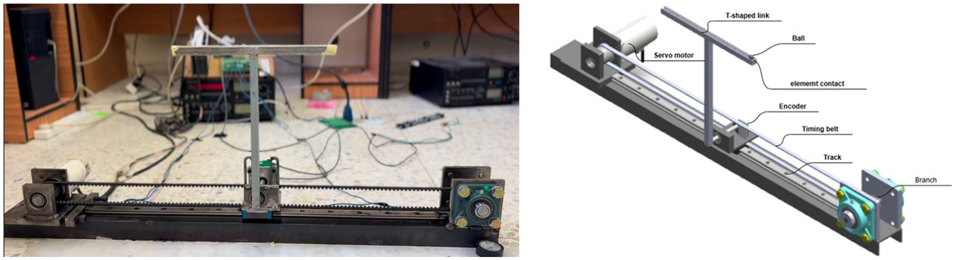
BTIP experimental platform: (a) photograph of the real setup showing the cart, timing-belt drive, and T-shaped pendulum and (b) CAD model illustrating main components: servo motor, encoder, timing belt, track, and T-link carrying the rolling ball. The system measures and controls three outputs: cart position x, pendulum angle θ, and ball displacement r.
These measurements are captured using two optical angular encoders—one at the joint and another monitoring the motor shaft. The system input is the torque generated by a servomotor, which drives the pulley that moves the cart. The controller calculates this torque in real time to: keep the pendulum balanced vertically, follow a desired cart trajectory, reject external disturbances.
A real-time control system is implemented on a PC with data acquisition (DAQ) hardware, while signal conditioning, filtering, and isolation circuits ensure accurate and noise-free communication between sensors, actuators, and the DAQ.
Inverted–pendulum dynamics underlie many real systems. Wheeled self-balancing transporters such as the Segway are modeled as wheeled inverted pendulums. 17 Humanoid locomotion planners employ the Linear Inverted Pendulum Model (LIPM) to generate stable walking and push-recovery patterns. 18 Moreover, reusable launch vehicles stabilize a tall, underactuated body during vertical landing—a control task analogous to inverted-pendulum stabilization. 19 These examples highlight the broad applicability of inverted-pendulum control principles and motivate the BTIP as a compact experimental benchmark for validating advanced controllers.
The main contributions of this study can be summarized as follows: (i) development of a novel experimental platform, the BTIP, that extends conventional cart–pendulum setups by introducing a coupled ball–beam motion; (ii) complete nonlinear modeling of the BTIP system using the Euler–Lagrange formulation, capturing all coupling effects between the cart, pendulum, and rolling ball; (iii) design and implementation of optimal and state-feedback controllers, including a LQR with integral action, for real-time stabilization; (iv) integration of observer-based estimation and real-time actuation using MATLAB/Simulink and NI hardware; and (v) experimental validation demonstrating stable operation and accurate tracking, confirming the system’s potential as a benchmark for advanced control research.
The remaining sections of this paper are as follows. Section 2 presents the mathematical modeling of the BTIP system using the Euler–Lagrange formulation. Section 3 outlines the design and simulation of state feedback controllers, including pole placement and extended LQR methods. Section 4 discusses simulation results and observer performance evaluation. Section 5 describes the real-time electrical interfacing and actuation subsystem, including DAQ integration and hardware implementation. Finally, Section 6 presents the experimental validation of the proposed control strategies and their real-time performance on the BTIP platform. Section 7 summarizes the key findings and outlines directions for future research.
Mathematical modeling
To establish the mathematical model of the BTIP mechanism, several simplifying assumptions are introduced to preserve the essential nonlinear dynamics while maintaining analytical tractability. Specifically, it is assumed that: (i) rolling between the ball and beam occurs without slip; (ii) Coulomb friction in joints, bearings, and drive components is negligible; (iii) small-angle approximations are invoked only during linearization for controller synthesis; (iv) the DC motor operates within its rated linear torque range without sustained saturation; and (v) structural flexibility and other high-frequency unmodeled dynamics are neglected.
The BTIP geometry, coordinate definitions, and fundamental Euler–Lagrange formulation follow the baseline modeling framework reported in the literature, 13 which detailed the full nonlinear derivation of this mechanism. For completeness and transparency, the present work restates the essential modeling steps, expands the intermediate energy formulation, and clarifies the transition from the energy expressions to the compact matrix representation used for control design.
Mechanism description and generalized coordinates
The BTIP consists of a cart translating along the x–axis, an inverted pendulum link of length L with its center of mass located at L
G
from the pivot O, and a ball that rolls freely along the beam attached to the link tip, forming the T-shaped configuration shown in Figure 2. The generalized coordinates are defined as

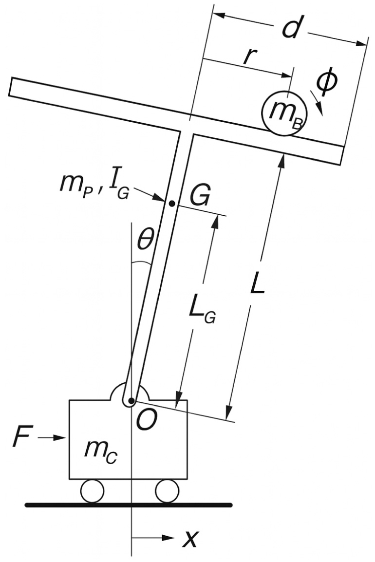
Schematic of the BTIP model.
Velocities follow by differentiation, and the ball’s angular velocity under the rolling-without-slip condition is
Energy-based derivation
The total kinetic and potential energies of the system are
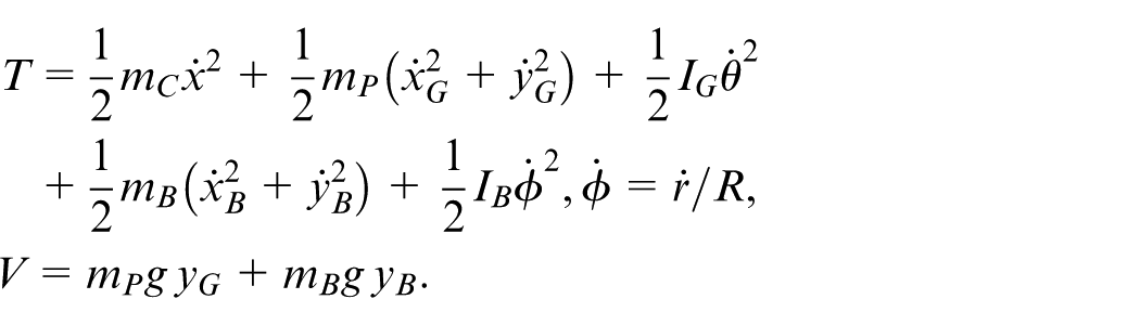
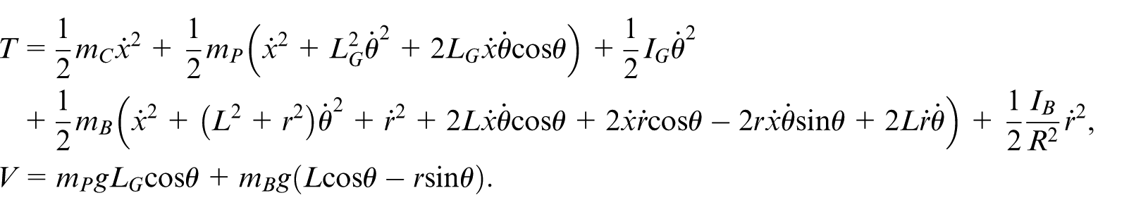
Substituting the kinematic relations yields the expanded form of the kinetic and potential energies,
Using the Lagrangian

with generalized forces
where the mass-inertia matrix
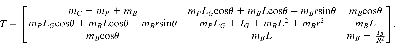
and the state vector is
State-space representation and linearization
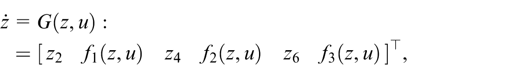
Defining
the system can be linearized around the upright equilibrium

Physical parameters
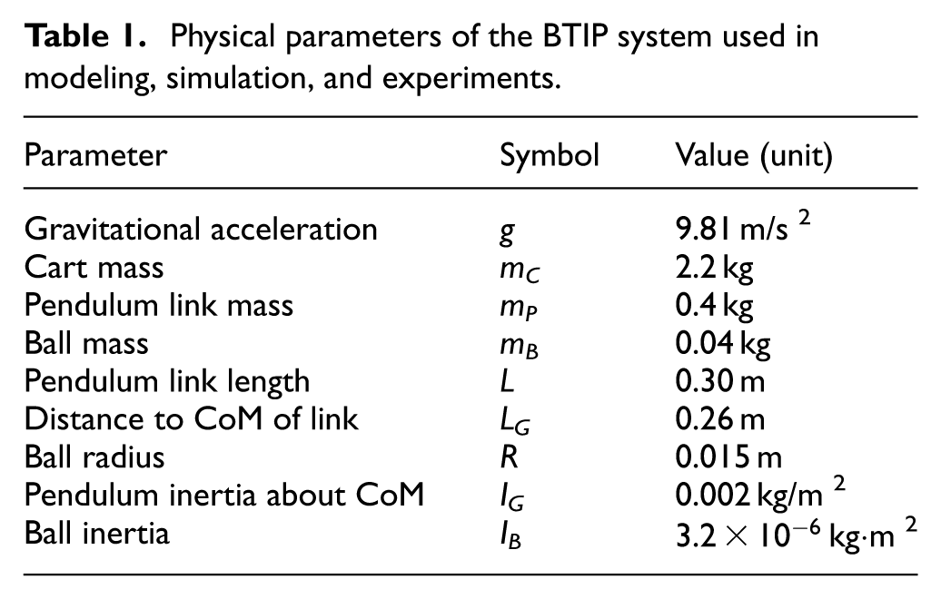
The physical parameters used in modeling, simulation, and experiments are listed in Table 1.
Physical parameters of the BTIP system used in modeling, simulation, and experiments.
Model-based control design and simulation for BTIP
Following the development of a detailed mathematical model for BTIP, it is essential to formulate and validate appropriate control strategies that can stabilize this inherently unstable and under-actuated system.
In this work, two model-based control approaches are considered for the BTIP system: pole placement and LQR. Additionally, an extended LQR controller is developed by augmenting the standard LQR formulation with an integral action to eliminate steady-state errors. Throughout the paper, the term extended LQR refers specifically to LQR-based state-feedback control combined with integral tracking.
Model-based control design serves as a critical intermediate step, enabling simulation-driven evaluation of control algorithms before real-time implementation. By applying the derived nonlinear and linearized dynamic models, this section focuses on designing state feedback controllers using pole placement and LQR techniques, in addition to observer-based estimators for unmeasured states.20–22
MATLAB and Simulink environments provide a flexible simulation framework, allowing for time-domain analysis of the system’s response under various control schemes. These simulations not only verify the controller’s performance in stabilizing the pendulum and maintaining the ball’s position but also reveal potential limitations and fine-tuning requirements. Furthermore, such offline simulations ensure safe and efficient validation of control logic, thereby reducing development time and minimizing risks associated with direct hardware experimentation. Hence, the model-based design approach forms a primary framework for robust, efficient, and safe implementation of real-time control in the BTIP platform.
State feedback control implementation
State feedback control is a widely used technique for stabilizing under-actuated and unstable systems like the BTIP. This approach relies on full or partial knowledge of the system’s states to directly control the cart position, pendulum angle, and ball displacement. The main goal is to place the closed-loop system poles in positions that ensure stable behavior, fast response, and minimal steady-state error.
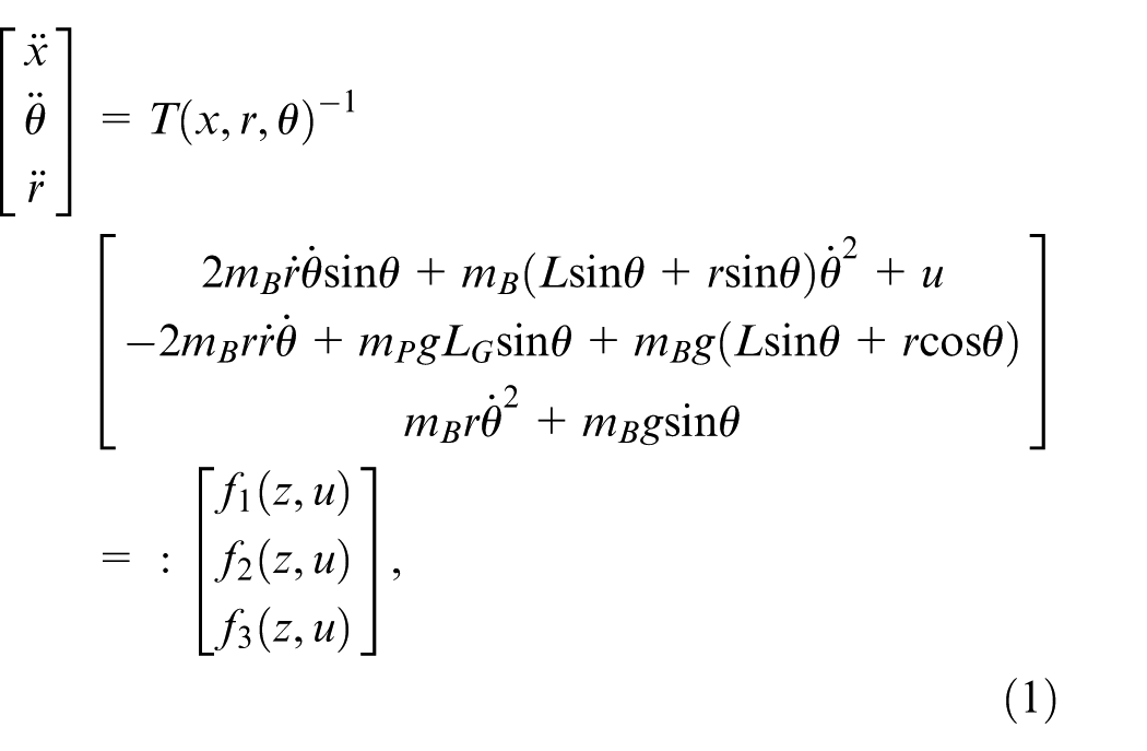
In the BTIP system, the state-space model derived from the dynamic equation (1) is used to design the feedback gain matrix either through pole placement or optimal control methods such as the LQR. The control law is expressed as
However, we can write the system in the form:
To do this, we use the characteristic equation:

Here, I is the identity matrix of size 6 × 6, and
In practice, MATLAB provides a useful function called place(.) which helps automatically calculate the values of k i needed to put the poles in the desired location.
For reproducibility, the pole–placement feedback gain used in the study is

Optimal control using LQR
The LQR method is applied in this work to design an optimal state-feedback controller for the BTIP system. It complements the earlier state-feedback approach discussed in Section 3.1 and is used for performance comparison. LQR provides a systematic means to balance state deviations and control effort by minimizing a quadratic cost function, thereby ensuring stability under suitable design conditions. Its robustness and computational efficiency have made it a standard technique for controlling under-actuated and unstable systems, as well as in robotic and mechatronic applications. 25
The LQR method aims to minimize the following performance index:

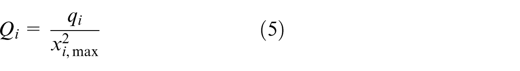
where Q is a positive semi-definite matrix that weights the system states, and R is a positive definite matrix that weights the control input. These matrices are chosen to reflect the importance of each state and the acceptable level of control effort. In our design, the elements of Q are scaled according to the expected maximum values of the states:
The matrix R is scalar since the system has a single actuator, and it penalizes large control inputs.
Using MATLAB’s lqr() function, the continuous-time algebraic Riccati equation is solved to compute the optimal gain matrix K, resulting in the control law:
The implemented LQR feedback gain is

The closed-loop behavior is then determined by the eigenvalues of
For the BTIP system, the controller handles multiple degrees of freedom and ensures both the pendulum remains upright and the ball stays centered. The LQR controller is also combined with an observer to estimate any states that are not directly measurable, and the full setup is validated using nonlinear Simulink simulations.
Overall, LQR provides an efficient and robust solution for the BTIP system, supporting stability and low-energy operation even in the presence of system disturbances and modeling imperfection, however, for more details, see, e.g.26–30
Our controller choices follow established practice for under-actuated unstable mechanisms. State-feedback and LQR give a transparent baseline for stabilization and effort–performance trade-offs.23,24,29 Recent studies refine LQR tuning and analyze robustness for inverted-pendulum variants.26–28 For larger model mismatch and disturbances, nonlinear and intelligent designs are widely reported: sliding-mode and related underactuated strategies, 22 fuzzy control,5,6,31 and neural-network controllers, 7 with direct LQR–SMC–NN comparisons. 20 When operating across large angles, swing-up plus stabilization remains standard.1–3 Beyond classical designs, fractional-order optimal regulators have shown improved transients on inverted-pendulum platforms. 16 These references motivate our use of extended LQR with integral action and an observer as a reliable baseline, and they outline clear upgrade paths when stronger robustness or large-angle operation is required.
Simulation results of the BTIP system
To validate the control strategies developed in Section 3, simulation studies were carried out in MATLAB/Simulink using the complete BTIP system model. The objective was to stabilize the pendulum in the upright position while maintaining the ball centered on the horizontal beam, even in the presence of external disturbances and varying initial conditions. System parameters were based on the physical prototype, and both pole placement and extended LQR controllers were implemented for performance comparison.
In order to enforce zero steady-state error for step reference inputs, an integrator is added to the control loop. This integrator introduces an additional state, denoted as z a , which accumulates the tracking error over time. As a result, the original six-state BTIP system becomes an augmented seven-state system. The six original states include the cart position and velocity, pendulum angle and angular velocity, and ball position and velocity. With the inclusion of the integrator state, the augmented state-space model is expressed as:
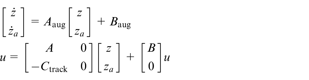
where Ctrack selects the output to be tracked (typically the cart position). This augmentation increases the system type, enabling accurate tracking and robust rejection of step disturbances.
To ensure that the entire system remains controllable and observable, standard rank tests were conducted in MATLAB. The controllability matrix

was evaluated for both the original and augmented models. The original system yielded a rank of 6, while the augmented system had a rank of 7, confirming full controllability in both cases. Likewise, the observability matrix
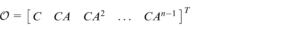
was also found to have full rank, indicating that the complete internal state can be reconstructed from output measurements. These results validate the suitability of the BTIP system for state-feedback and observer-based control.
In our simulations, the BTIP prototype was modeled using the physical parameters summarized in Table 1. These include the masses, geometric dimensions, and inertias of the cart, pendulum, and ball. Only the essential mechanical properties are listed for clarity, while all numerical values are omitted here to avoid redundancy with the table.
To estimate the unmeasured states of the BTIP system, a full-state observer must be developed based on the original linearized six-state model, excluding the integrator used for tracking. The observer reproduces the plant dynamics and incorporates a corrective feedback term based on the output estimation error to reconstruct the full state vector using measurable outputs and known inputs. Without loss the generality, the observer is constructed to estimate the system states based on available measurements and known inputs. Its dynamic formulation is expressed as:


where
This structure enables real-time reconstruction of the full system state using partial measurements, forming the basis for state-feedback control in the presence of unmeasured dynamics.
The observer gain matrix L was computed using pole placement to ensure rapid convergence of estimation errors. The observer poles were placed significantly left of the system poles to guarantee fast error decay. Observability was confirmed by computing the observability matrix and verifying full rank (
The observer estimates the six physical states of the BTIP system: cart position and velocity, pendulum angle and angular velocity, and rotating arm position and velocity associated with the ball. These estimated states are essential for implementing the state-feedback LQR controller applied to the augmented system that includes tracking. The observer design ensures robust and accurate real-time state estimation under dynamic and uncertain conditions, enabling effective disturbance rejection and closed-loop control.
Full-state feedback control was implemented using the previous extended LQR to achieve system stabilization. A state observer was incorporated to estimate unmeasured states, and integral action was added to eliminate steady-state errors. Pole placement techniques, including also extended LQR, were employed to refine system performance, ensuring robust trajectory tracking and effective disturbance rejection.
The simulations were initialized with nonzero conditions to evaluate controller performance under perturbed states. Specifically, the pendulum angle was set to
Simulated responses of the BTIP under extended LQR control. Subplots (a)–(f) show the state trajectories: (a) cart position x, (b) cart velocity
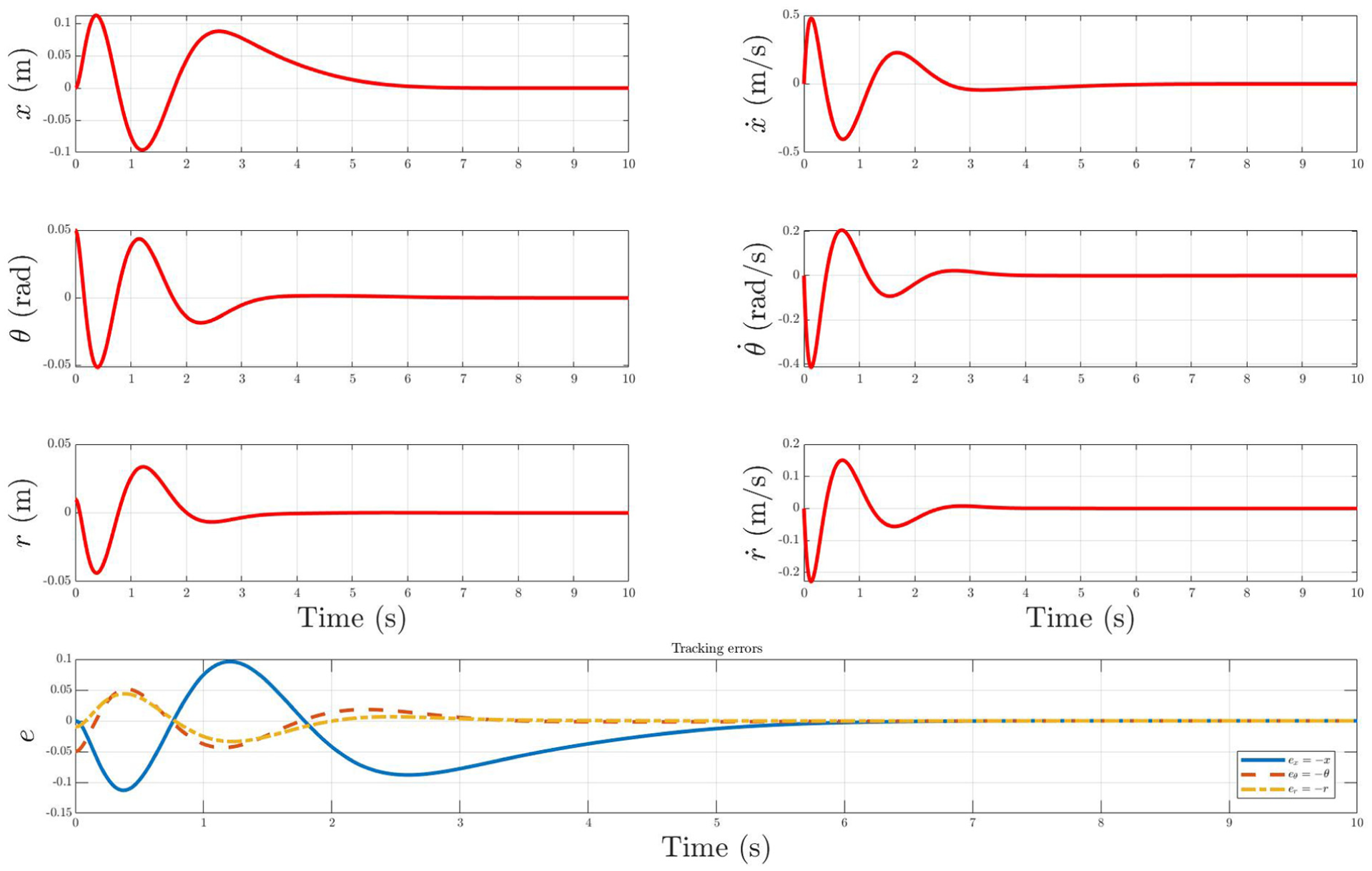
Simulated responses of the BTIP under state-feedback (pole-placement) control. Subplots (a)–(f) display the six system states: (a) cart position x, (b) cart velocity
A comparison of the responses indicates that while both controllers successfully drive the states to equilibrium, the observer-based state-feedback design achieves faster convergence and reduced overshoot, particularly in the pendulum angle and ball position, compared to the standard LQR case.
Rea-time electrical interfacing and actuation subsystem of BTIP
The electrical subsystem plays a basic role in achieving real-time stabilization and actuation within the BTIP system. It is responsible for interfacing key components—including sensors, actuators, and conditioning circuits—with the controller, enabling accurate state measurement and dynamic response. 32 To ensure the T-link remains upright and the ball maintains balance, a closed-loop control scheme should be implemented. This involves acquiring real-time feedback from states’ sensors (here optical encoders for states x and θ as well as a potentiometer for state r) to continuously monitor the cart position, pendulum angle, and ball displacement. 30 These signals are processed through filtering and conditioning circuits and digitized using high-precision DAQ cards. All experiments were sampled at 1 kHz using an NI PCI-6024E multifunction I/O board (16-bit analog inputs, 2 analog outputs, and integrated counters). 33 Analog sensor signals were passed through first-order low-pass conditioning filters with a cutoff near 100 Hz before digitization to attenuate electrical noise. Quadrature encoder channels were connected through the PCI-QUAD04 interface, which employed its built-in digital noise filter to suppress spurious pulses. 34 In Simulink, the numerically differentiated velocity signals were further smoothed using a low-pass Butterworth filter around 50 Hz. All filtering occurs prior to the observer and controller stages, while the control input is left unfiltered.
The controller, executed on an xPC Target platform, computes the necessary torque command, which is then applied to a high-performance AC servomotor via a dedicated driver operating in torque control mode. This layered structure, combining inner and outer feedback loops as shown in Figure 5, enables robust actuation and responsive stabilization of the BTIP system under dynamic conditions.
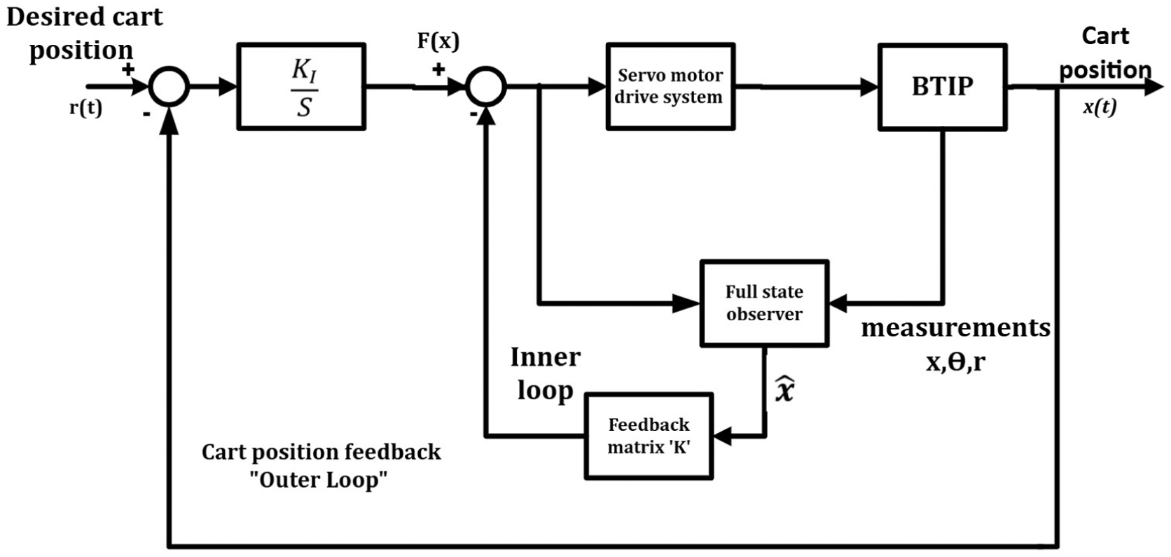
Block diagram of the inner–outer loop control architecture for the BTIP.
The real-time sensor signals, in our work, are processed by a controller hosted on a desktop computer running the xPC Target real-time environment. This controller calculates the required actuation torque and transmits it to the servomotor driver, which in turn commands the motor to move the cart precisely. To ensure accurate and reliable interfacing, two DAQ cards are employed, along with external signal conditioning and filtering circuits to minimize noise and maintain signal integrity. Additionally, an initial positioning mechanism is incorporated to correctly place and balance the ball at the center of the T-shaped beam. An overview of the electrical subsystem connections is shown in Figure 6.
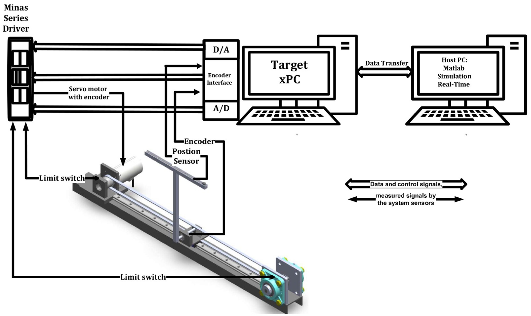
Schematic diagram of the electrical subsystem of the BTIP setup.
The xPC Target framework, provided by MathWorks as a toolbox within MATLAB Simulink, enables rapid prototyping, testing, and deployment of real-time control systems using standard PC hardware and peripherals such as DAQ cards. This setup employs a dual-PC architecture, where the host PC is used to design and simulate the controller, which is then downloaded to the target PC for real-time execution. The target PC interfaces directly with the physical system and operates independently to meet strict real-time constraints. Key advantages of this approach include seamless controller updates, online parameter tuning, flexible connectivity options (serial, Ethernet, or standalone), and support for a wide range of DAQ interfaces. These capabilities make the xPC Target an ideal platform for implementing and validating the control strategy of the BTIP system, particularly in educational and research environments.35,36
In this work, a Panasonic three-phase AC servomotor (model MSMA042A1E) 37 driven by the MINAS A-series driver (model MSDA043A2A26) is utilized to actuate the BTIP cart along a linear track via a rope-pulley mechanism.38,39 This motor is selected for its low inertia, high torque at low speeds, and high-precision control-features that suit with the dynamic requirements of the system. The motor operates at a rated power of 400 W and a nominal speed of 3000 rpm, resulting in a calculated rated torque of approximately 1.3 N.m. Although designed for a 200 V three-phase power supply, the system allows for operation from a standard single-phase source. The integrated incremental encoder provides high-resolution feedback with 2500 pulses per revolution. The motor can sustain radial and axial loads of up to 245 and 98 N, respectively. Built-in overload protection permits operation above the rated torque within time-limited conditions. Torque boundaries are configured via driver parameters (such as Pr5E), and the driver continuously monitors torque to prevent mechanical stress or damage. The system’s electrical connectivity includes encoder interfacing through the CN SIG port, serial communication with the PC via CN SER, and control signal input through the CN I/F connector.
In the BTIP system, a set of additional components are integrated to enhance control flexibility, signal fidelity, and system safety. A Panasonic servo motor and MINAS A-series driver operate in torque control mode to provide precise actuation, with control voltage applied via external circuits. The system supports RS232C communication for real-time parameter tuning and monitoring.
Safety features include over-travel inhibition, using limit switches and programmable parameters to prevent mechanical damage due to excessive motion, as illustrated in Figure 7. Sensor feedback is essential to the closed-loop design: three incremental optical encoders monitor the pendulum and ball dynamics, while a potentiometric linear sensor tracks linear displacement. The optical encoders—based on quadrature signals—allow accurate position and direction estimation.
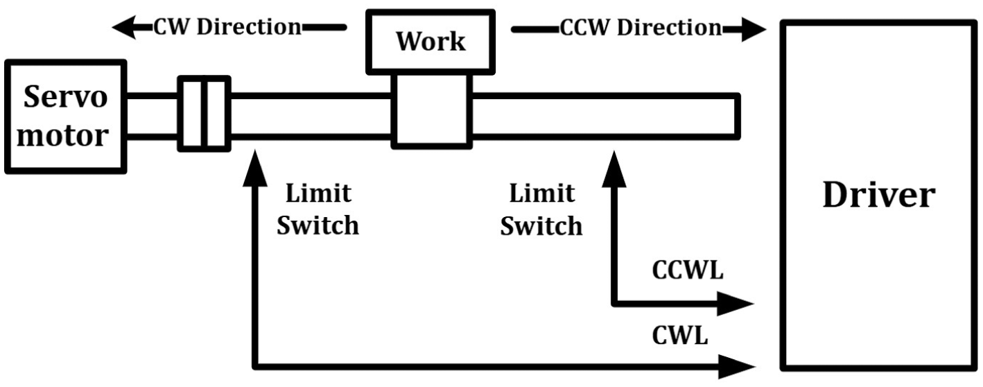
Limit-switch safety configuration in the BTIP system.
To interface these sensors and actuators, two DAQ cards are used: the NI6024E for analog I/O operations33,40 and the PCI-QUAD04 for high-precision encoder signal processing. 34 Signal conditioning circuits—including analog filters and isolation—are implemented to reduce electrical noise and protect DAQ ports. This combination of smart sensing, reliable communication, and robust acquisition ensures the BTIP system performs with high fidelity under real-time constraints.
Moreover, the mechanical subsystem of the BTIP system includes the cart, T-shaped link, ball, and associated transmission elements, all of which are designed to deliver stability, precision, and real-time responsiveness. A closed-loop control approach is employed to maintain the T-shaped pendulum in its upright equilibrium while accurately guiding the ball to follow the desired trajectory along the beam. The system’s core mechanical components include the linear rail, cart and carriage assembly, timing belt and pulley mechanism, and the T-link-ball configuration, see Figure 1. These parts are carefully selected and developed to minimize friction and inertia, eliminate backlash, and ensure smooth and efficient motion. An initial ball positioning mechanism is also integrated to place the ball in its starting position before activation. 17
On the other hand, meeting the system’s high dynamic performance requirements requires the use of low-friction materials, precise alignment, and durable construction. The cart is actuated via a three-phase servo motor coupled to a timing belt, allowing for a lightweight design and enhanced motion accuracy. Special attention is given to the bearing assemblies supporting the pulleys and the T-link rotation, where flexible ball bearings and adhesive compounds (e.g. Poxy Ball) are used to mitigate undesired motion and improve mechanical stability. Additionally, a detailed mechanical analysis incorporating both translational and rotational dynamics was conducted to ensure robustness under operational loads.
Simulink real-time implementation and DAQ integration
In addition to the core electrical components, the BTIP system utilizes a sophisticated computer and information subsystem to enable real-time control, data acquisition, and flexible development. The control framework is implemented using the xPC Target platform (Simulink Real-Time), a real-time operating system provided by MathWorks that facilitates rapid prototyping and hardware-in-the-loop (HIL) testing.35,36 This setup employs a dual-PC architecture: a host PC is responsible for controller design, model simulation, and parameter tuning, while a dedicated target PC executes the control algorithm in real time, interfacing directly with the physical hardware via DAQ cards. MATLAB and Simulink are used to develop the system model and controller logic, which are then compiled and deployed to the target PC using Real-Time Workshop. With support for serial, Ethernet, or standalone execution, the xPC Target environment provides high flexibility for experimental validation and controller refinement.
All real-time experiments were conducted using MATLAB Version 7.0.1 and Simulink Version 6.1 with Real-Time Workshop Version 6.1 and xPC Target Version 2.6.1. The development environment ran on a Microsoft Windows platform supported by The MathWorks. The target PC’s interface card was of a type supported by Simulink Real-Time (e.g. Intel Pro/100S or SME 1208BT, based on NE2000 or Intel I82559 chipsets). A standard crossover RJ45 or coaxial cable was used for host–target communication; coaxial was preferred for longer distances. TCP/IP networking provided reliable high-speed data exchange (up to 100 Mbit/s) and greater scalability compared to RS-232 serial links. The host computer was a standard personal workstation (Intel Core i7, 3.4 GHz CPU, 16 GB RAM, Windows 10 Pro, 64-bit).
To ensure efficient development and verification of the BTIP control system, the xPC Target platform is used in combination with National Instruments DAQ hardware, including the NI6024E card 33 for analog input/output and the PCI-QUAD04 card 34 for quadrature encoder signal processing. Signal paths are configured in Simulink using built-in I/O blocks, enabling seamless integration of sensor feedback and actuator control. The design process begins with building a Simulink model configured with fixed-step solvers suitable for real-time execution. Upon compiling the model, an executable is deployed to the target PC, which boots into the xPC Target kernel from a bootable disk or drive. During operation, real-time data logging, scope visualization, and online parameter tuning are supported, allowing for closed-loop experimentation and refinement. This environment enables researchers to monitor sine wave generation, analog signal acquisition, and encoder feedback in real time. The high sampling rate and low-latency characteristics of the DAQ hardware ensure accurate representation of the BTIP dynamics. Ultimately, the integration of xPC Target with MATLAB/Simulink and high performance DAQ hardware provides a robust platform for developing and validating advanced control strategies within the BTIP system.
Experimental validation
To experimentally validate the proposed control strategies, this section presents the real-time implementation of various controllers on the BTIP system mounted on a moving cart. The experimental objectives are to evaluate the system’s ability to stabilize the pendulum in the upright position, balance the ball at arbitrary locations along the T-beam through cart actuation, achieve accurate cart trajectory tracking, reject external disturbances, and validate full state observers under nonlinear dynamic conditions.
The experimental platform utilizes a servomotor to actuate the cart’s motion, while high-resolution optical encoders provide real-time feedback on position and angular displacement. The control system is implemented using Simulink Real-Time on a dedicated target PC, interfaced with two DAQ cards: the NI PCI-6024E, responsible for analog control signal output and sensor data acquisition, and the NI PCI-QUAD04, which manages quadrature encoder interfacing. For additional technical details, refer to Section 5.
This modular hardware-software configuration allows seamless switching between control architectures, facilitating robust comparative analysis, system identification, and observer validation. Figure 8 illustrates the complete physical setup used in the laboratory, including the cart, pendulum structure, data acquisition interfaces, and host-target communication. The figure provides a clear view of the integrated testbed employed during the experiments.
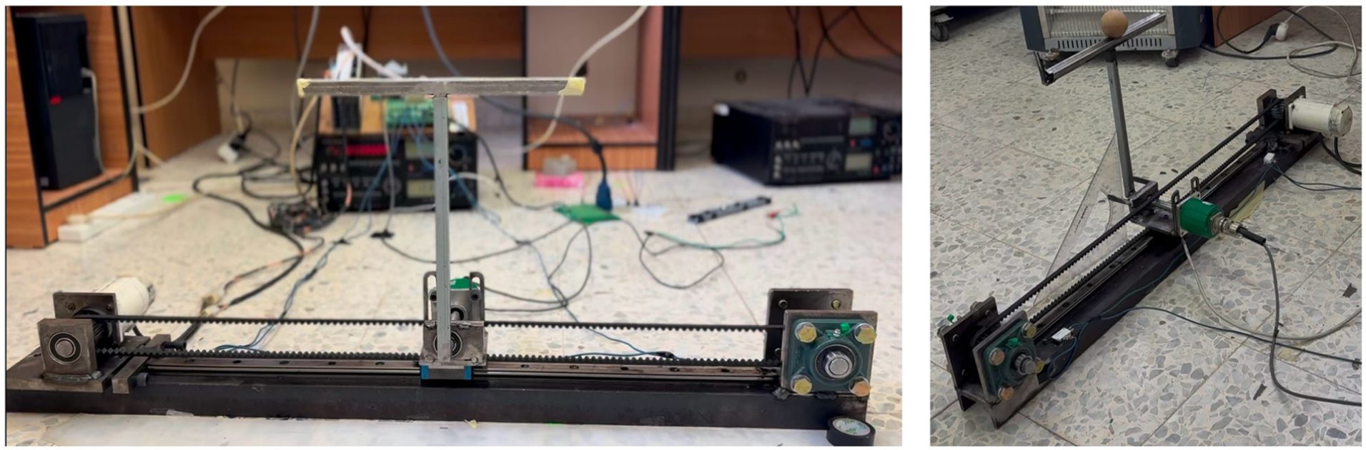
Experimental setup of the BTIP system: (a) front view showing the motorized cart, vertical pendulum link, and horizontal T-bar supporting the rolling ball and (b) isometric view displaying the complete laboratory assembly, including the timing-belt drive, servo motor, encoder, and data acquisition hardware.
BTIP system experiment: Robust LQR implementation
In the real-time experiments on the BTIP system, the robust LQR controller was implemented following the theoretical design outlined in Section 3.2. However, the feedback gains were intentionally reduced to prevent actuator saturation, which can occur when the control signals exceed the physical limits of the motor. While this adjustment protected the hardware, it also led to slower system responses and noticeable oscillations. These performance issues were primarily caused by unmodeled mechanical flexibilities in the cart and actuator assembly, such as structural bending and elastic couplings. These dynamics introduced additional vibrations that were not captured in the original control model, reducing the controller’s effectiveness during initial testing.
To enhance the real-time performance of the BTIP system, a two-degree-of-freedom (2-DOF) control design was introduced. This structure separates the tasks of reference tracking and disturbance rejection, allowing each to be tuned independently. By decoupling these objectives, the controller achieved smoother tracking responses while effectively suppressing unwanted vibrations. Additionally, the control system was modified to include extra damping and compliance, making it better suited to the system’s actual mechanical behavior, which includes structural flexibilities not accounted for in the original model. These improvements resulted in a softer and more stable controller that preserved the ability to balance the pendulum and keep the ball centered, even under dynamic and uncertain real-world conditions.
Figure 9 presents the experimentally measured state responses of the BTIP system under LQR control. In this experiment, the cart was commanded to move
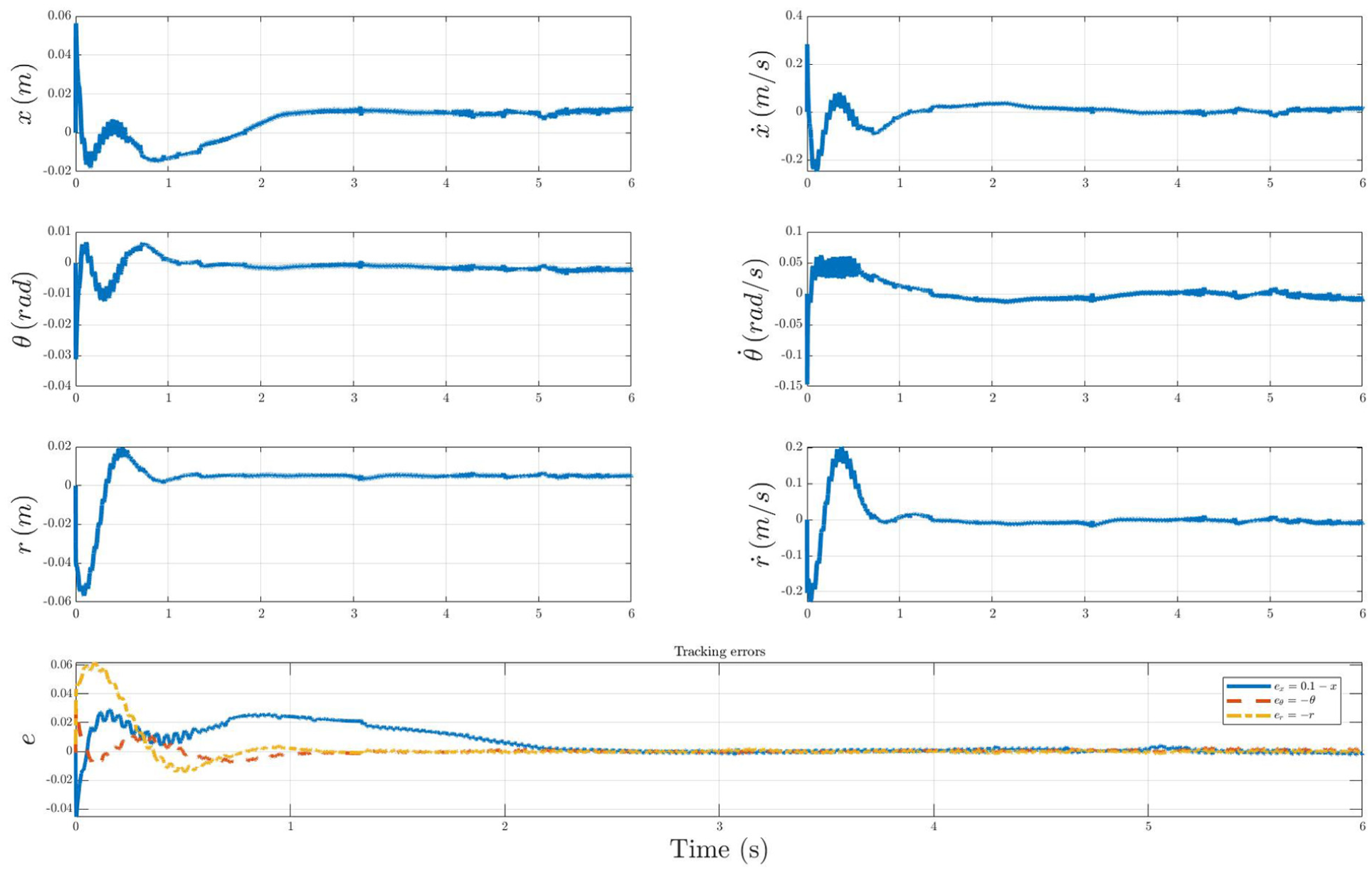
Experimental responses of the BTIP under robust LQR control. Subplots (a)–(f) show the measured state trajectories: (a) cart position x, (b) cart velocity
Figure 10 presents the control input force applied to the cart. A large initial control effort was required to stabilize the system quickly, after which the force remained within a bounded range of approximately ±5 N. This indicates that the controller achieved rapid stabilization while maintaining efficient and safe operation without causing actuator saturation.
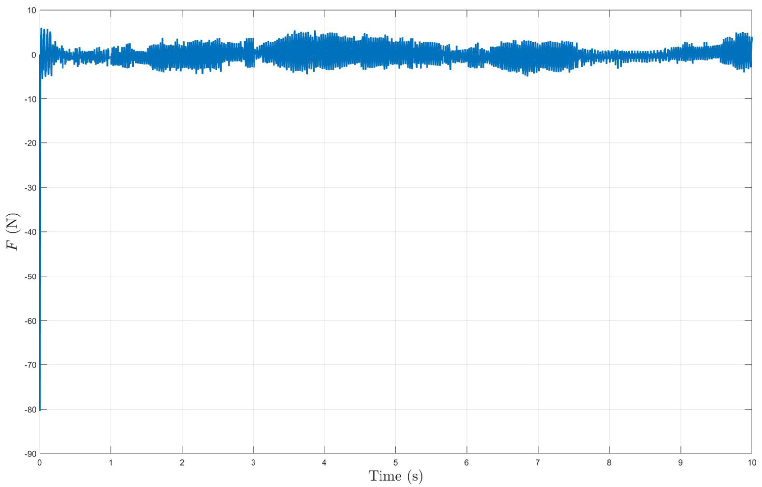
Experimental control input force F(t) applied to the BTIP under LQR control, showing actuator response during stabilization and steady operation.
Observer and pole placement performance evaluation
To further validate the effectiveness of the observer-based control strategy, a 6-s experimental evaluation was conducted using a pole placement controller on the BTIP system. The observer demonstrated high accuracy in estimating the full state vector, including the cart, pendulum, and ball dynamics. For instance, the cart position estimation achieved a root mean square error (RMSE) of less than 1 mm, confirming precise state reconstruction. Despite the presence of high-frequency noise in the measured velocity and angular velocity signals, the observer effectively filtered these disturbances, yielding smooth and consistent estimates across all states.
The closed-loop system exhibited stable and well-damped behavior. The pendulum angle remained within a small oscillation band of
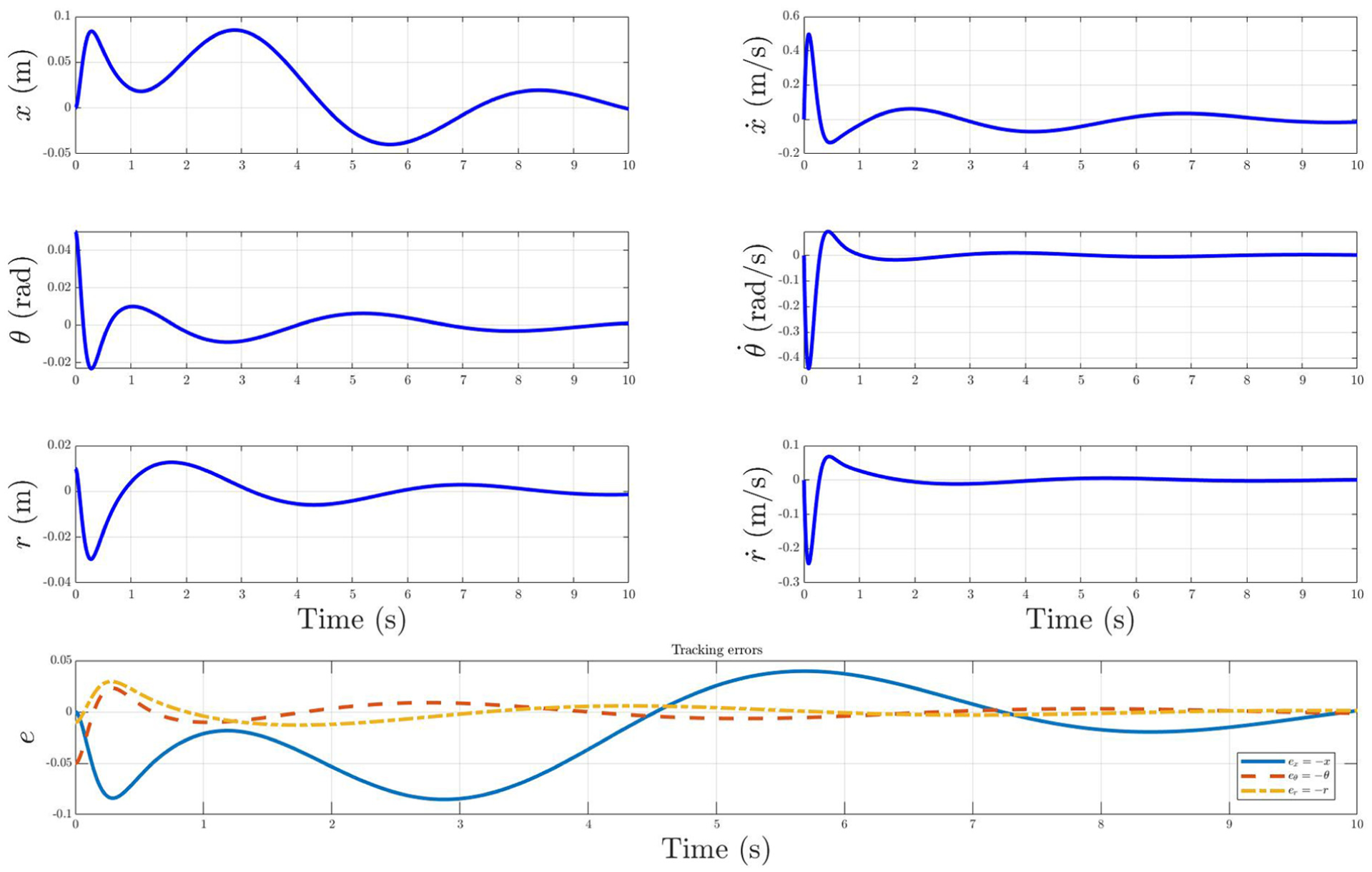
Figure 11 shows the experimentally measured state responses of the BTIP system under state-feedback control with an observer. The experiment was conducted under the same conditions as the LQR case, where the cart was commanded to move
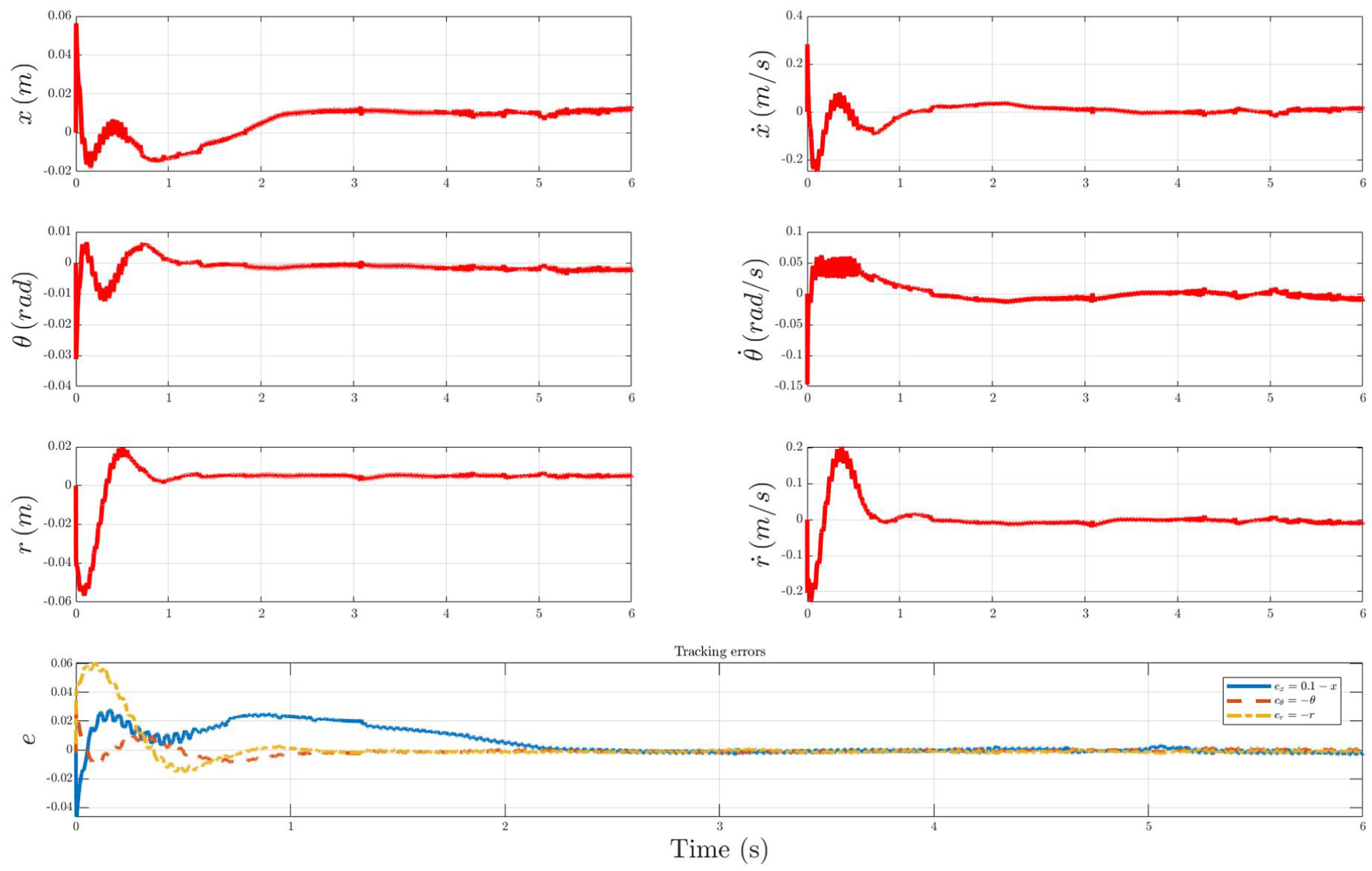
Experimental BTIP state and tracking-error responses under robust state-feedback (pole-placement) control. The plots display the measured states and the corresponding tracking errors e
x
,
The control force generated by the pole placement controller is shown in Figure 11. It reached a peak during the initial transient response but rapidly decayed to a steady-state range within
Quantitative measures for both LQR and state feedback methods (settling time
To further highlight the role of state estimation, the numerical Luenberger observer gain used in all experiments is explicitly given by
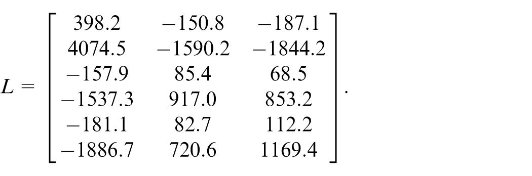
as obtained from the design procedure described in Section 4. To assess its contribution to closed-loop behavior, additional experiments were conducted for both the LQR and pole-placement controllers using direct sensor measurements only, that is, without the observer. The resulting trajectories are combined in Figure 12. In both cases, the measured states exhibit higher noise sensitivity and small steady-state offsets compared with the observer-based implementations. These comparisons confirm that the observer significantly improves noise rejection, estimation smoothness, and overall closed-loop stability.
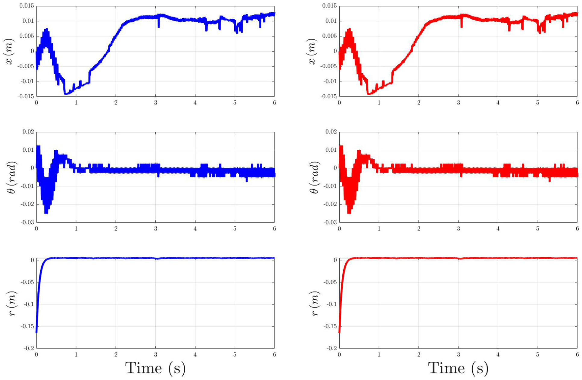
Experimental BTIP state responses under robust LQR (blue) and pole-placement (red) control without the observer. Increased measurement noise and minor steady-state offsets are visible compared with the observer-based results, confirming the observer’s effectiveness in enhancing estimation and control performance.
To further assess the robustness of the designed controllers, external disturbances were intentionally applied to the pendulum by manually tilting it during operation while maintaining the ball on the beam. Figure 13 illustrates the measured responses under such disturbance conditions. The first column (blue profiles) corresponds to the LQR controller, whereas the second column (red profiles) represents the pole-placement state-feedback controller. In both cases, the pendulum successfully returned to the upright configuration with the ball remaining stably on the beam, confirming effective disturbance rejection and recovery. Minor oscillations were observed immediately after each disturbance but were rapidly attenuated by the controllers.
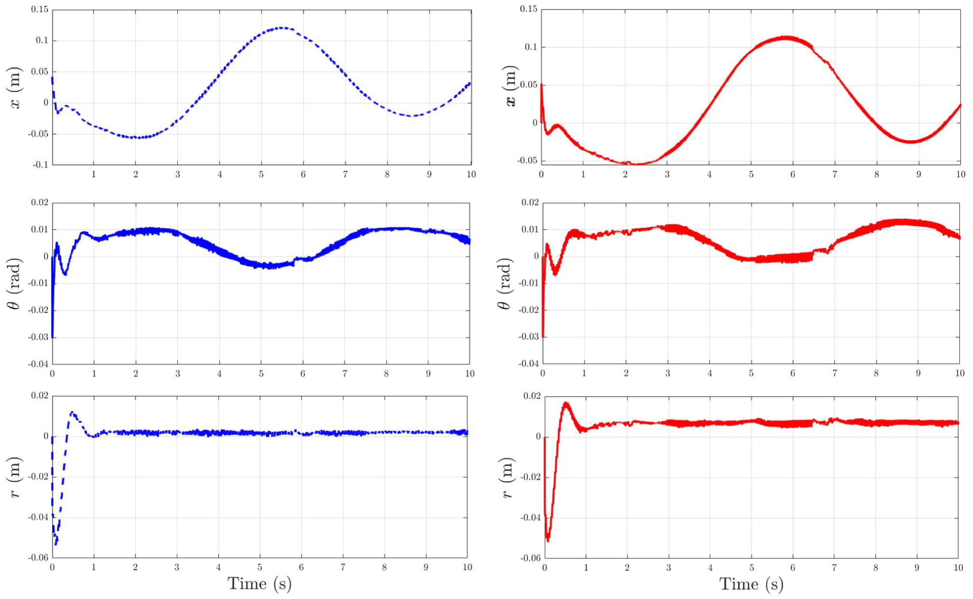
Disturbance–rejection experiment with repeated manual tilts of the pendulum while the ball remains on the beam.
Figure 14 presents three representative snapshots captured during the disturbance–rejection experiment. Frame (a) shows the pendulum under an externally applied tilt disturbance, frame (b) illustrates the transient recovery phase as the controller drives the pendulum toward the upright position, and frame (c) depicts the stabilized configuration with the ball centered on the beam. These images correspond to the experimental sequence previously analyzed in Figure 13 and confirm the controller’s ability to recover from disturbances while maintaining ball stability.
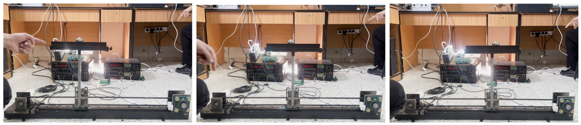
Snapshots from the disturbance–rejection experiment (Supplemental Video 1): (a) initial external tilt disturbance, (b) transient recovery phase, and (c) stabilized upright configuration with ball centered on the beam.
Conclusion
This paper presented the modeling, control design, and real-time experimental validation of a novel BTIP system mounted on a motorized cart. The system dynamics were derived using the Euler–Lagrange formulation and expressed in state-space form to facilitate linear control design. Two control strategies; pole placement and extended LQR were developed and evaluated through simulation and hardware experiments. To address unmeasured states, a full-state observer was implemented and validated, demonstrating high accuracy in real-time estimation and robust performance under sensor noise and disturbances.
The real-time implementation was achieved using a modular Simulink Real-Time framework interfaced with DAQ hardware, enabling flexible controller deployment and seamless integration with the BTIP platform. Experimental results confirmed the ability of the proposed controllers to stabilize the pendulum, track reference trajectories, and maintain the ball at the center of the beam, all while ensuring efficient control effort and resilience to modeling uncertainties.
Overall, the BTIP system serves as an effective platform for validating advanced control algorithms in under-actuated, nonlinear systems. Future work will explore the integration of adaptive, robust, or learning-based control techniques to further enhance performance under parameter variations and unknown disturbances.
Supplemental Material
sj-jpg-1-mac-10.1177_00202940261423404 – Supplemental material for Design, modeling, and control of a ball-on-T-shaped inverted pendulum system with experimental validation
Supplemental material, sj-jpg-1-mac-10.1177_00202940261423404 for Design, modeling, and control of a ball-on-T-shaped inverted pendulum system with experimental validation by Jasem Tamimi, Yousef Sweiti, Lojain Sharabati, Yazan Nairoukh and Yazan Tahboub in Measurement and Control
Supplemental Material
sj-jpg-2-mac-10.1177_00202940261423404 – Supplemental material for Design, modeling, and control of a ball-on-T-shaped inverted pendulum system with experimental validation
Supplemental material, sj-jpg-2-mac-10.1177_00202940261423404 for Design, modeling, and control of a ball-on-T-shaped inverted pendulum system with experimental validation by Jasem Tamimi, Yousef Sweiti, Lojain Sharabati, Yazan Nairoukh and Yazan Tahboub in Measurement and Control
Supplemental Material
sj-jpg-3-mac-10.1177_00202940261423404 – Supplemental material for Design, modeling, and control of a ball-on-T-shaped inverted pendulum system with experimental validation
Supplemental material, sj-jpg-3-mac-10.1177_00202940261423404 for Design, modeling, and control of a ball-on-T-shaped inverted pendulum system with experimental validation by Jasem Tamimi, Yousef Sweiti, Lojain Sharabati, Yazan Nairoukh and Yazan Tahboub in Measurement and Control
Footnotes
Ethical considerations
Not applicable; this study did not involve human participants, human data, human tissue, or animals.
Author contributions
Jasem Tamimi: Conceptualization, methodology, analysis, software development, results drafting, supervision, writing of the manuscript and preparing as well as applying revisions. Yousef Sweiti: Conceptualization, analysis. Lojain Sharabati: Experimental implementation, software development, and drafting of the results. Yazan Nairoukh: Experimental implementation, software development, and drafting of the results. Yazan Tahboub: Experimental implementation, software development, and drafting of the results.
Funding
The authors received no financial support for the research, authorship, and/or publication of this article.
Declaration of conflicting interests
The authors declared no potential conflicts of interest with respect to the research, authorship, and/or publication of this article.
Data availability statement
The datasets generated and/or analyzed during the current study are not publicly available but are available from the corresponding author upon reasonable request.
Supplemental material
Supplemental material for this article is available online.