
Abstract
Synchronous motion is an essential function for multi-motor drive systems, which have been applied in high-precision space collaborative manipulators, satellite systems, and other aerospace industrial fields. To maintain the desired high precision of synchronization in the case of motor inverter fault, a coordinated fault-tolerant control (FTC) scheme is proposed in this paper for the drive system consisting of multiple brushless direct current motors with an adjacent cross-coupling structure. Firstly, the proposed scheme develops a robust coordinated FTC control law based on synergetic control theory, in which the expected manifold of the fault-tolerant synergetic controller is devised to guarantee the synchronization preferentially in the fault case. To enhance system robustness, the control framework incorporates a disturbance observer and an adaptive technique to effectively mitigate the impact of load disturbances. Secondly, the asymptotic stability of the FTC system is proven via Lyapunov theory. Finally, simulation and test experiments on the speed synchronous control of a triple-motor system verified the effectiveness of the developed FTC strategy.
Keywords
Introduction
Multi-motor drive systems have been successfully applied in high-precision space station collaborative manipulators,1,2 twin-gyros synchronization attitude control of spacecraft, 3 satellite antenna servo systems,4,5 distributed electric propulsion aircraft, 6 and other aerospace industrial fields, where high synchronous precision among motors is vital to system reliability, safety, operating performance, and missions. Thus, numerous synchronous control strategies for multi-motor drive systems have been developed in recent years, such as coupling-based (including cross-coupling, deviation coupling, adjacent coupling, and relative coupling),6,7 concurrent, 4 and leader-following approaches. 8 Zhang et al. 9 analyzed the prevalent synchronization control structures employed in multi-motor systems, with applications in industrial drones, robotic arms, and electric vehicles. These structures included master command control (namely concurrent), master–slave control and coupling-based controls. The authors also introduced an improved deviation coupling strategy incorporating a virtual motor to achieve multi-motor speed synchronization by synchronization coefficient and tracking coefficient. The coefficients were optimized using the particle swarm optimization algorithm. Masroor et al. 8 investigated the brushless direct current (BLDC) multi-motor speed synchronization problem, a critical challenge in applications such as aerospace, unmanned aerial vehicles, and robotic manipulation. It was addressed by using the leader-following multi-agent system consensus and variable-structure model reference adaptive control algorithm. It is indicated by Yang and Chang 3 and Niu et al. 10 that the concurrent and leader-following methods suffer from inherent deficiencies of the poor anti-interference and the low response speed. They are usually applied in the early aerospace systems or other industrial scenarios like paper-making and textile manufacturing with low-synchronization requirements. In modern satellites and space structures applications, the coupling-based synchronous strategies are often employed with other techniques to meet higher levels of synchronization.7,11 For examples, Weng et al. 6 proposed a thrust synchronous control strategy for multiple propulsion motors with relative coupling structure in distributed electric propulsion aircraft to keep the synchronous speed of each motor. To meet the synchronization control requirements of multi-servo motor drive systems in radar antennas and air defense artillery, Wang et al. 7 developed an adaptive robust H∞ control method that integrates an average deviation coupling strategy with distributed synchronization controllers. Han et al. 11 developed an attitude synchronous control strategy by combining cross-coupling structure and non-singular fast terminal sliding mode control for satellite formation systems under disturbances. However, the synchronization of systems may be degraded or failed due to component faults, abnormal disturbances or system parameter variations. For instance, power inverters are the key actuators in BLDC motor-based servo systems which are often used in satellite antennas.4,5 It has been reported that more than 82.5% faults were caused by inverters. 12 Such faults may not only lead to accidents in the faulty motor subsystem, but also propagate through the coupling structure to impair normal subsystems, causing the entire system to lose synchronization. Therefore, it is required to find a proper fault-tolerant control (FTC) strategy for the high synchronization applications.
At present, many FTC methods can tolerate the faults of power inverters, sensors and windings components in motor systems (see e.g. Lv and Li, 13 Bhuiyan et al. 14 ). Most of them rely on complex fault diagnostic modules to obtain in-depth failure information, and their FTC controllers are designed for failed motors without leveraging the latent useful information in multi-motor synchronous systems. To address such problems, an active FTC strategy with improved command filtered backstepping control scheme was proposed by Wang et al. 15 for a four-motor synchronously driving servo system with symmetric mechanical structure. This approach can isolate the faulty motor while maintaining relatively high synchronization among the remaining fault-free motors under unexpected motor faults. Mao et al. 16 integrated model-based and data-based methods to tolerate sensor faults in multi-motor synchronous systems with deviation coupling structures. Recently, sliding-mode control (SMC) has exhibited outstanding performance advantages in addressing complex fault-tolerant issues due to its superior disturbance rejection capability. 17 It is also noted by Bhuiyan et al. 14 that the generalized FTC schemes such as SMC and adaptive extended Kalman filter can ensure a moderate performance. However, conventional SMC inherently suffers from discontinuities, and the complex coupling structures in multi-motor systems exacerbate system chattering. Some improved SMC methods such as second-order SMC 18 and super-twisting algorithm 19 introduced significant complexity, although they demonstrated superior chattering suppression and control performance. Consequently, these methods are difficult to be applied directly in FTC of multi-motor synchronization systems due to complex coupling-based structure. 16
In recent decades, synergetic control (SC) approach, similar to SMC, 20 has provided solutions for solving the high-precision control problem of nonlinear systems, and applied in the fields such as healthcare, 21 aerospace,22,23 and power apparatus. 24 The design of macro-variable in SC can reconcile multiple control indices and lead the system to a reference trajectory in finite time. It not only brings about the advantages such as robustness, fast response, high accuracy and order reduction, but also eliminates the chattering in SMC through the designed macro-variable or manifold. 21 Huang et al. 25 proposed a fixed-time synergetic control method employing load torque observer to synchronize the speeds of wheels in a multi-interior permanent magnet synchronous motor traction system, leveraging the relative coupling structure. To the best of our knowledge, only a few studies have focused on the FTC issue for coupling-based synchronization of multi-motor systems subject to inverter faults.
Based on the foregoing discussion, a coordinated FTC strategy with an adjacent cross-coupling structure is proposed in this paper to maintain the desired synchronous precision for a multi-BLDC-motor drive system against inverter fault. The main contributions are stated as follows: (1) The proposed FTC scheme achieves the desired synchronization through coordinated operation among all motor subsystems, rather than relying solely on the faulty motor subsystem as in conventional approaches. This method features simple decision logic and does not require a stringent fault detection and diagnosis unit or complex FTC mechanisms. (2) A numerical FTC controller is developed based on SC theory, in which the expected manifold is designed to give priority to synchronous precision while mitigating the negative effects of the coupling structure on FTC performance. The resulting control algorithm can be readily executed by numerical control programs without inducing the chattering phenomenon of conventional SMC. (3) An adaptive weighting coefficient and an exponential convergent disturbance observer are adopted to enhance the FTC performance. (4) The asymptotic convergence of the FTC system is proven via Lyapunov stability analysis.
The remainder of this paper is organized as follows: The motor model with inverter faults and the FTC problem are described in Section 2. The coordinated fault-tolerant controller is developed in Section 3. In Section 4, the simulative and experimental results are demonstrated to verify the proposed FTC method. Conclusions are given in Section 5.
Problem formulation
Adjacent cross-coupling synchronization structure
Figure 1 is a typical speed synchronous control system with n BLDC motors and adjacent cross-coupling structure. 26 The tracking error for the i-th motor control subsystem is

where w i (t) is the angular speed output; θ i (t) is the reference speed input after compensation from the coupling structure.

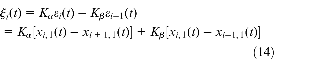
where xd(t) is the command speed; ξ i (t) is the compensation of synchronous errors, denoted by
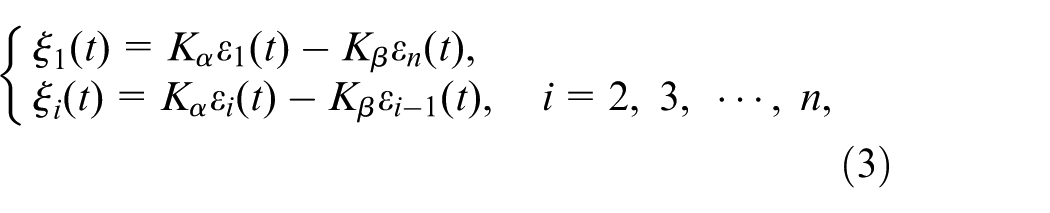
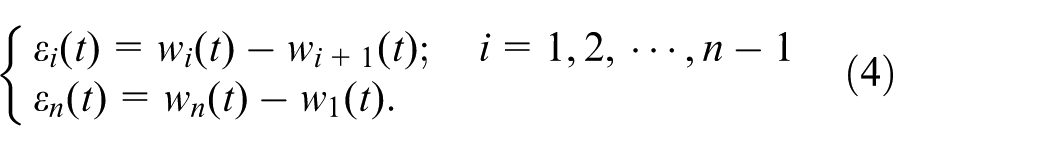
where K α > 0 and K β > 0 are the gain coefficients, and ε i (t) is the synchronous error of speed between the i-th and (i+1)-th motor control subsystems, expressed by
Both tracking error δ i (t)→0 and synchronous error ε i (t)→0 are satisfied in normal case. Whereas, when the fault occurs in motor inverter, it can cause the entire system synchronization failure. To address this problem, the inverter fault model is firstly deduced in the sequel.
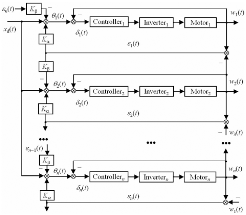
Multi-motor speed synchronous control system with adjacent cross-coupling structure.
Inverter fault model of BLDC motor and problem statement
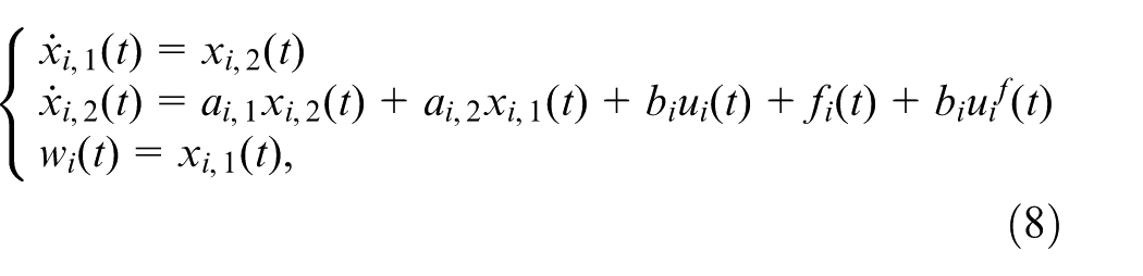
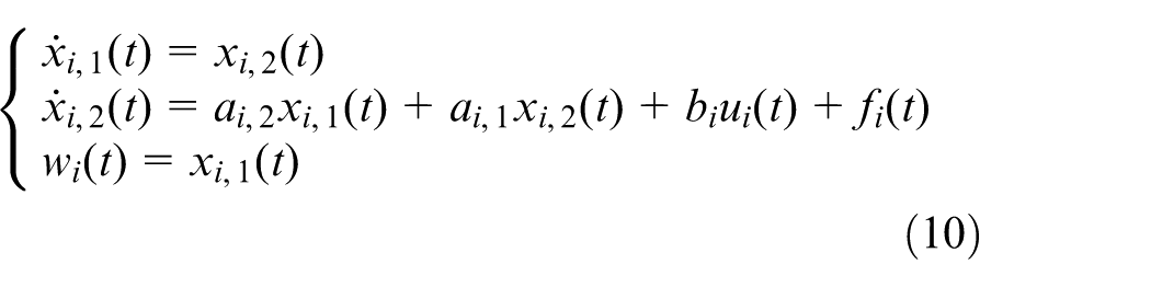
According to BLDC servo-motor operating principle, the following simplified state-space model
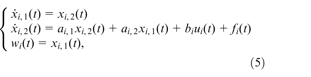
is derived by Kirchhoff Circuit Laws 27 for the i-th motor control subsystem, where x i ,1(t) is the speed, u i (t) is the output voltage of inverter, a i ,1 = −(2D(L−M)+RJ)/(2J(L−M)), b i = −(Kt)/ (2J(L−M)), f i (t) = −RTL(t)/(2J(L−M)) with df i (t)/dt = 0, a i ,2 = (−RD−KeKt)/(2J(L−M)), R is the resistance of winding, L and M are the coefficients of self-inductance and mutual-inductance, J is the moment of inertia, Kt is the torque coefficient, Ke is the coefficient of back electromotive force (EMF), D is the coefficient of viscous damping, TL(t) is the load torque with gradual variation and the assumption dTL(t)/dt = 0. According to the commutative principle of inverter with pulse width modulation (PWM), u i (t) is also expressed by
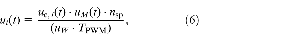
where uc,i(t) is the controller output, uM(t) > 0 is the bus DC voltage of inverter, TPWM is the period of PWM signal, uW is the nominal value of bus DC voltage, nsp is the value of PWM counter. Consequently, we have u i (t) = uc,i(t) in normal case when ignoring the influences of PWM precision and power switch transient durations in the motor drive system.
Common faults in inverters include bus DC voltage fluctuations, electrical component damage, and PWM pulse counting biases. They are usually manifested by the abnormal drop of inverter output voltage, and lead to the abnormal deceleration of motor. 28 Such kinds of inverter faults are equivalently regarded as the abnormal changes of output u i (t) in (6), which are the gain type faults theoretically. Thus, the output voltage of the faulty inverter in system (5) can be denoted by

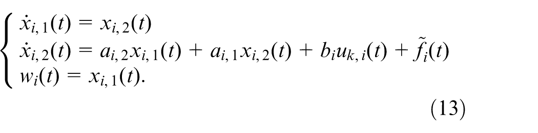
where g(t)∈[GL, GH] is the fault factor depicting the severity, GL and GH are the lower and upper bounds of g(t) with 0 < GL < 1 and GH ≥ 1. The inverter is fault free when g(t) = 1, otherwise the anomaly or fault happens. Consequently, the faulty system model of (5) is
where
To this end, the FTC problem investigated in this paper is stated as follows: As for the multi-motor synchronous control system in Figure 1 subject to inverter fault in one of the BLDC motor subsystems, a coordinated FTC strategy is studied to preferentially guarantee the expected synchronous speed of the overall multi-motor system, thereby ensuring the satisfied speed synchronous errors among the motors.
Coordinated fault-tolerant control based on synergetic control theory
Coordinated synchronous FTC design
The proposed coordinated FTC scheme is illustrated in Figure 2. It embraces n BLDC motor-drive subsystems and an FTC decision-making module, where a fault detector and a fault-tolerant SC (FTSC) controller are included in every motor control subsystem. For the i-th subsystem, fault detector is used to get inverter fault information by the M-SPRT algorithm in Appendix 1. It provides a Boolean flag F i (t) to the FTC decision-making module, where F i (t) = 0 indicates fault-free state and F i (t) = 1 otherwise. FTC decision-making module generates the Boolean signal s i (t) based on the current values of all flags F i (t). s i (t) enables the fault-tolerant executer i (see Figure 3) in the corresponding FTSC controller. The decision-making logic is:
When the multi-motor synchronous system in normal case,
When inverter fault occurred in the j-th subsystem, F j (t) = 1 and F i (t) = 0 (i = 1,2,…, n, i≠j), the outputs s j (t) = 1 and s i (t) = 0 accordingly;
If inverter faults occurred in more subsystems,
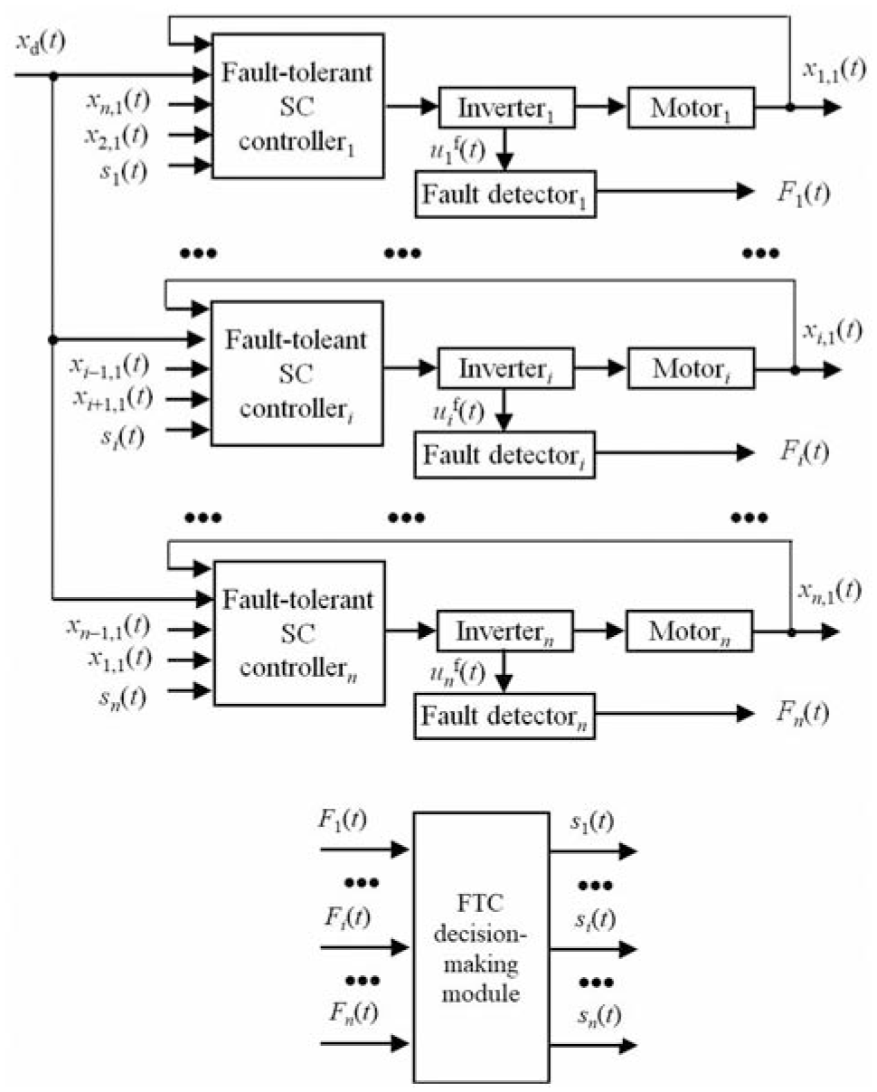
Coordinated FTC scheme for multi-motor speed synchronous control system.
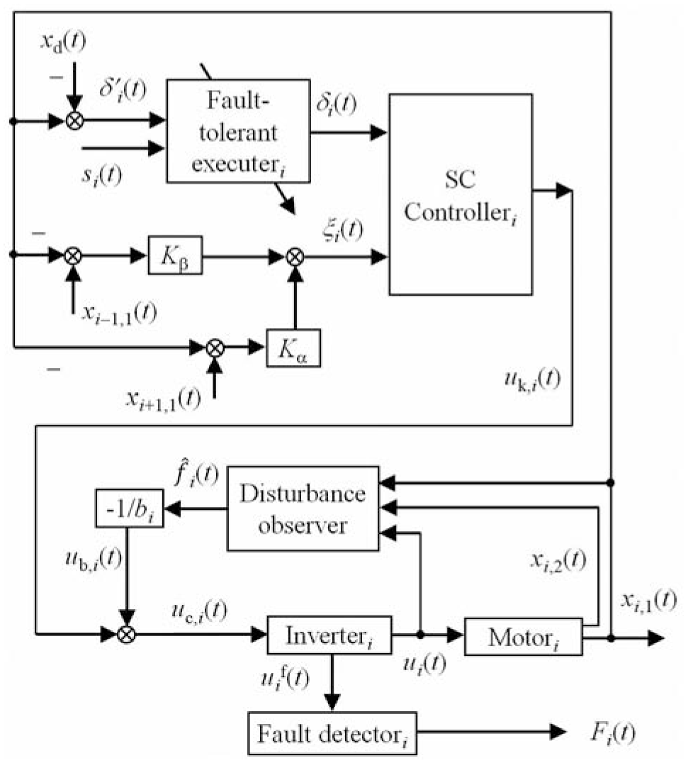
FTSC controller scheme for i-th motor control subsystem.
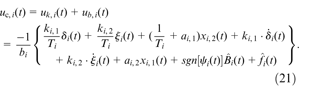
As for the FTSC controller design in Figure 2, we take the i-th subsystem as example to demonstrate its procedure. The proposed FTSC controller structure is illustrated in Figure 3. It has five inputs (xd(t), x i ,1(t), x i −1,1(t), x i +1,1(t) and s i (t)), and the control signal is

where uc,i(t) is the robust coordinated FTC signal, uk,i(t) is the FTSC control signal and ub,i(t) is the compensation signal for load disturbances.
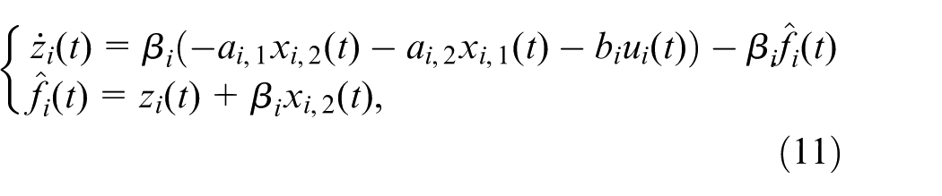
First of all, a disturbance observer with exponential convergence is adopted to attenuate the load influence. According to (5), the following model is got
for the i-th subsystem, where f i (t) is the bounded load disturbance with df i (t)/dt = 0. Complying with the principle in Fazal and Choudhry 32 and Song and Zhang, 33 we develop the following exponential convergence observer
to estimate f
i
(t) in real-time and improve the robustness of FTSC controller, where z
i
(t) is the observer state,
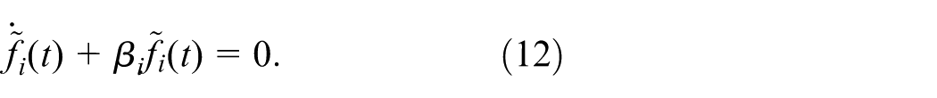
It is obvious from (12) that the error is exponentially convergent. Thus, the compensation law for the load disturbance is designed by
Next, the FTSC control law uk,i(t) is designed. Based on the adjacent cross-coupling structure, the compensation of synchronous error is produced by
from the errors in (3) and (4). Based on SC theory, the most important step of designing SC controller is to find a macro-variable and a control law based on the manifold equation and the system state-space model. 32 For the i-th subsystem we devise the following manifold

by combining the system variables x i ,2(t), ξ i (t), and δ i (t), where ψ i (t) is the macro-variable, k i ,1 > 0 and k i ,2 > 0 are the designed weighting coefficients. When an inverter fault is detected, the proposed FTC strategy will prioritize the synchronization. The operating logic of the fault-tolerant executer i in Figure 3 is thus designed as follows to enable real-time computation of δ i (t) using the flag s i (t) and timely adjust the manifold for achieving FTC goal.
When inverter fault is not detected, flag s i (t) = 0. All motor subsystems are running synchronously and tracking their command xd(t), the tracking error δ i (t):=δ i ′(t)=xi,1(t)−xd(t);
When inverter fault is detected, flag s i (t) = 1. The equilibrium point of the entire synchronous system will alter due to the fault, and the new equilibrium point (representing the updated synchronous speed of the multi-motor system under fault condition) cannot be determined a priori. To realize the FTC goal in this case, we use a high-pass filter in Zhao 34 to approximate the variation of tracking error in the manifold, namely,
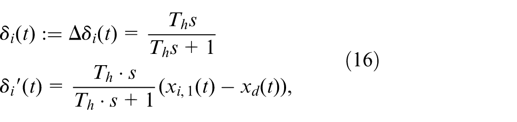
where Th > 0 is the time constant of the high-pass filter, s is the Laplace operator.
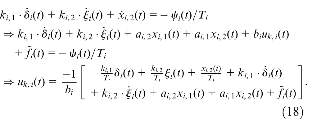
By substituting the compensation ξ i (t) in (14) and the above tracking error δ i (t) into the manifold (15), the following equation with first-order inertia feature

is yielded, where T
i
> 0 is the design parameter. We have
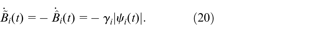
To further enhance the robustness of the FTC law against load disturbances, the upper bound B
i
> 0 with |
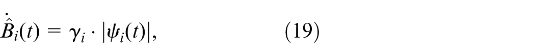
where γ
i
> 0 is the given adaptive coefficient. Then the dynamics of the estimation error
By virtue of the estimated value
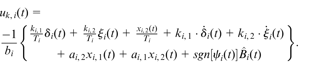
To this end, the robust coordinated FTC law is figured out by
Control parameters of the FTC law
From the previous design and analysis, we can find that the design parameters in control law (21) may vary only if they are greater than zero. It is preferable to tune these parameters for better synchronization. In practice, they are mainly empirical parameters and determined individually either through prior knowledge or a trial-and-error process. Among the design parameters, only k i ,1, k i ,2, and T i are closely related to the synchronization and are discussed here.
For the manifold (15), it is known based on SC theory that increasing k i ,1 can improve the tracking accuracy, but the regulating process becomes slower for the synchronous error. It is designed trade-off by the technique in Bastos et al. 35
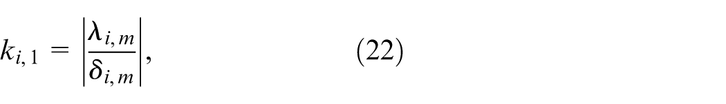
and then fine-tuned to meet the required tracking accuracy of the i-th subsystem, where λ i ,m is the nominal acceleration of motor and δ i ,m is the permitted maximal tracking error.
As for the time constant T i , the settling time τ i of the manifold convergence is about 3T i since its dynamics is described by (17) with the first-order inertial feature. Thus, we preset the value τ i in comply with the transient performance of motor system, and the time constant T i = τ i /3 can be obtained.
In terms of the weighting coefficient k
i
,2, it is noted from Remark 3 that the tracking error
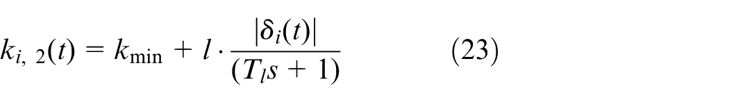
to determine the coefficient k i ,2, where kmin > 0 is the preset minimum value, l > 0 is gain coefficient, T l = 0.1 is the time constant of first-order inertia.
Stability analysis of fault-tolerant control system
The stability of the multi-motor synchronous system is analyzed based on Lyapunov stability theory. The Lyapunov candidate function is constructed by

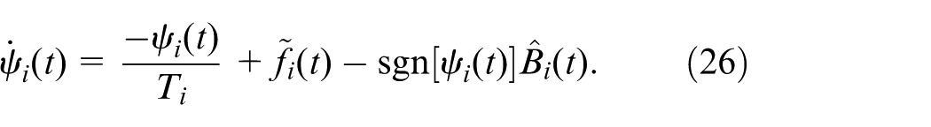
for the i-th subsystem. Differentiating the macro-variable ψ i (t) in (15) yields

Putting the control law (21) and the state equation (10) into (25) can obtain
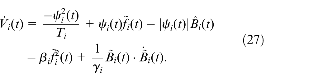
Now differentiating the Lyapunov function (24), and substituting (26) as well as (12) into (24) gets
Due to the upper bound
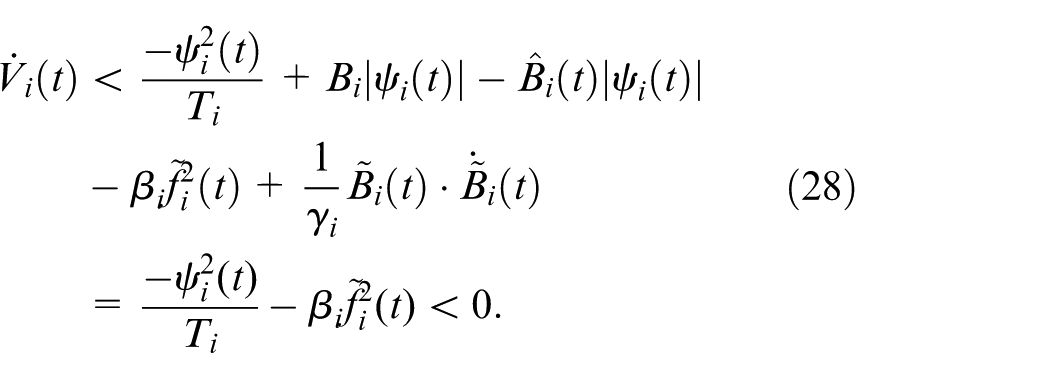
According to Lyapunov stability principle, the system is asymptotically stable, namely, the states of all subsystems will converge to the desired equilibrium points and manifolds.
Simulative and experimental verifications
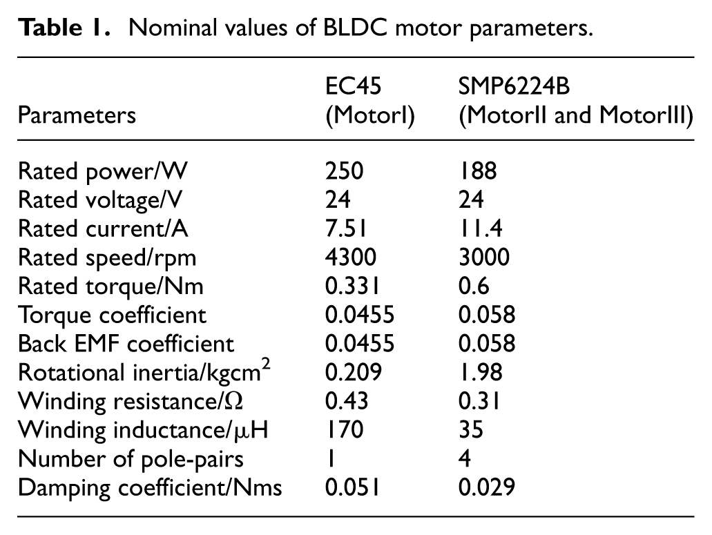
A multi-motor synchronous system consisting of three BLDC servo motors is used to verify the proposed FTC strategy. The system was constructed by adjacent cross-coupling structure as shown in Figure 1 with n = 3. One motor is EC45 made by MAXON Corporation of Swiss, the other two are SMP6224B motors made by Shanghai MINDONG Corporation of China. Their nominal values are presented in Table 1. The proposed FTC strategy was compared with the sliding mode fault-tolerant control (SMFTC) method, 17 and the adaptive coordination coefficient fault-tolerant (ACC) method 39 to demonstrate its superiority.
Nominal values of BLDC motor parameters.
SMC is promising for FTC of multi-motor synchronous systems.10,40 The control law for SMFTC method is designed based on the conventional SMC algorithm 17 with the following sliding mode function

and the control law
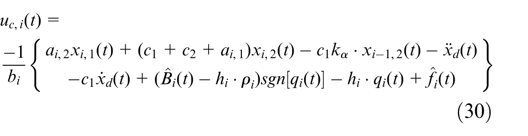
for the i-th subsystem, where error signal e i (t) = xd(t)-x i ,1(t); h i > 0, c1>0, c2 > 0, and ρ i > 0 are the gain coefficients. The verifications were carried out respectively by MATLAB/Simulink simulations and experimental test in our laboratory.
Simulative validation
In the simulations, the command speed was set by step signal from 0 to 30 rad/s in the beginning and further to 50 rad/s at t = 0.06 s, that is, xd(t) = 50 rad/s. The inverter fault in MotorI occurred at t = 0.1 s and resulted in the bus DC voltage dropped from the nominal 24 V to 14 V. At the same time, the load disturbance was imposed on MotorII with the rate 0.016 Nm/s. It can be omitted by comparing with the nominal torque 0.6 Nm, and so the parameters dTL/dt = 0 and df i /dt = 0. The overall system was operating with FTC function in the fault case.
By using the M-SPRT technique presented in Appendix 1, 30 the inverter fault was detected at t = 0.18 s. According to the proposed FTSC strategy, the fault detection information F1 = 1 activated the FTC decision-making module to export the flag s1 = 1, and further regulated the output uc,1(t) to perform the FTC function. While by ACC method the coordinated coefficients of the coupling synchronization control were manipulated to achieve the FTC objective. For SMFTC scheme, the motor control subsystems were manipulated by the control law (30) to tolerate the inverter fault.
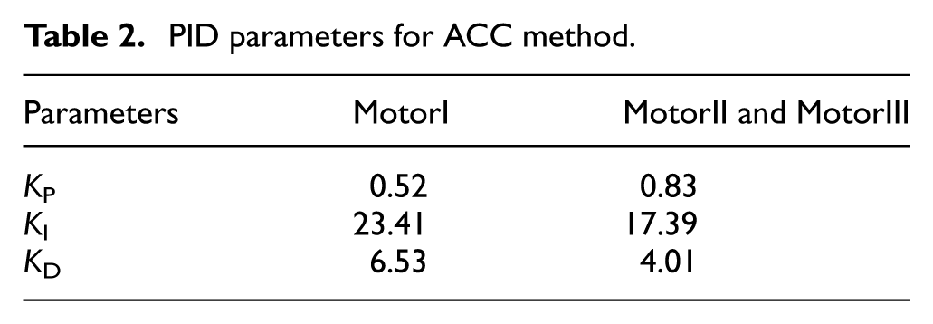
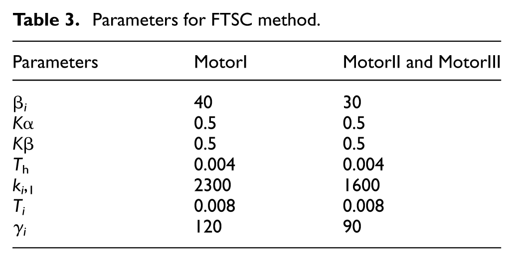
With respect to the control parameters determination of three FTC schemes, they can be firstly designed off-line following their techniques and then be readily adjusted in applications. Specifically, the regular PID control was adopted for ACC method. The resulted PID parameters are listed in Table 2 by the traditional poles-assignment technique, and the synchronous compensation coefficients are K α = K β = 0.5. For the proposed FTSC method, the designed parameters are shown in Table 3, and T l = 0.1, kmin = 1500, kmax = 4788, l = 900 in (23) for the adaptive coefficients k i ,2(t) in the simulation. Parameters in control law (30) for SMFTC method were as follows: h i = 0.004, ρ i = 17, c1 = 56 and c2 = 238 for MotorI; h i = 0.004, ρ i = 10, c1 = 5, and c2 = 42 for MotorII and MotorIII. To enhance the real-time performance of the three-motor synchronous system in simulations, we implemented the control algorithms for the above three FTC strategies by employing difference and cumulative sum operations in place of calculus operations. Furthermore, differential equations were solved using the fourth-order Runge-Kutta method and the improved Euler formula. Thereby, complex calculus-based computations were reduced to conventional algebraic operations. Consequently, the computational efforts were primarily manifested as multiplication/division operations, along with some addition/subtraction operations on the control parameter signals. Statistical analysis of the simulations indicated that within each synchronous control cycle (set to 4e–5s), the main computational cost lay in multiplication/division operations, while addition/subtraction imposed a minor burden. Among the FTC strategies, the PID algorithm in the ACC method required the fewest multiplication/division operations (only 6); the SMC algorithm in the SMFTC method required 33; and the control variable computations in the FTSC method entailed 36.
PID parameters for ACC method.
Parameters for FTSC method.
Figures 4 and 5 show the speed response and synchronous error curves of three motor control subsystems. In contrast, the superior synchronization was achieved by FTSC method in the FTC stage. It is obvious from Figure 5 that the maximum value 0.46 rad/s by FTSC method was better than both the max 1.59 rad/s by ACC method and 0.54 rad/s by SMFTC method. The errors by SMFTC generally fluctuated more than those by FTSC, although they were significantly better than those by the ACC method. The magnitudes of tracking errors are also illustrated in Figure 6. It is found that all the tracking errors were increasing notably during the FTC process, while FTSC and SMFTC methods responded faster than ACC method. They exhibited the comparable tracking performance overall. It is noted by observing the curves in Figures 5 and 6 that compared with ACC method, the other two methods enforced the more control efforts on the normal motors through the coupling structure to maintain preferentially the synchronization in the fault case, while the synchronous errors by FTSC method were generally smaller than those by SMFTC scheme, implying the superiority of our proposed method. Figure 7 shows the adaptive weighting coefficient k i ,2(t) of FTSC method. It is reasonable from the previous analysis that k1,2(t) increased with priority to suppress the worsening of synchronous error in MotorI when the fault happened. Subsequently, k2,2(t) and k3,2(t) increased simultaneously for MotorII and MotorIII through the coupling structure. By such a way the FTSC control law harmonized the operation of three motors to improve the synchronous precision and the stability during the fault tolerance process.
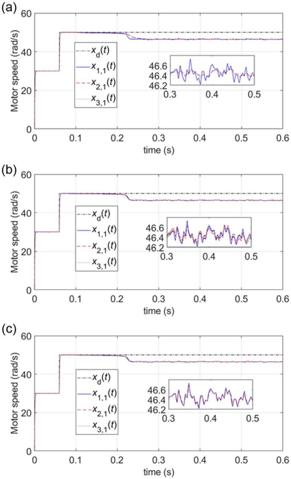
Speed response curves in the inverter fault. (xd(t): command speed; xi,1(t): the i-th motor speed (i = 1,2,3).): (a) by ACC method, (b) by SMFTC method, and (c) by FTSC method.
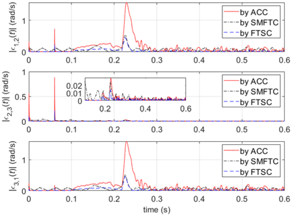
Magnitudes of synchronous errors in the inverter fault. (|ε1,2(t)|: between MotorI and MotorII; |ε2,3(t)|: between MotorII and MotorIII; |ε3,1(t)|: between MotorIII and MotorI.).
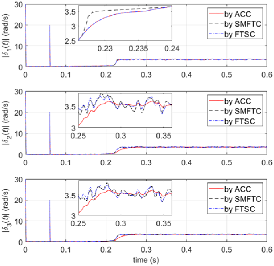
Magnitudes of tracking errors in the inverter fault. (|δ1(t)|: MotorI; |δ2(t)|: MotorII; |δ3(t)|: MotorIII.).
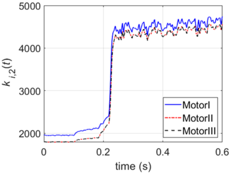
Adaptive weighting coefficient ki,2(t). (i = 1,2,3).
Experimental test
The experimental system was established abiding by adjacent cross-coupling structure. Its physical experimental platform and the schematic diagram of each motor control subsystem are shown in Figures 8 and 9, respectively. The controller of each motor subsystem was realized by DSP chip TMS320F28335. The drive module DRV8301 operated with inverter. The sampler was designed by high-precision resistor RX70 to get the inverter voltage for fault detection. The motor speed was measured by incremental encoder TS6014N135. CAN Bus and communication transceiver SN65HVD230CAN were used for data transmission among the motor control subsystems. Hall transducer was installed for detecting the armature current. Slider PL60 with nominal torque 11 Nm was used as the gradual load disturbance during the experiments. FTC control algorithms were realized on the μcos-II real-time OS by C language programing. The desired FTC indices were the maximum synchronous error less than 0.8 rad/s in the fault case and 0.5 rad/s in the steady state, the maximum synchronous error in the transient stage less than 3 rad/s, and the time duration no more than 0.5 s for fault detection.
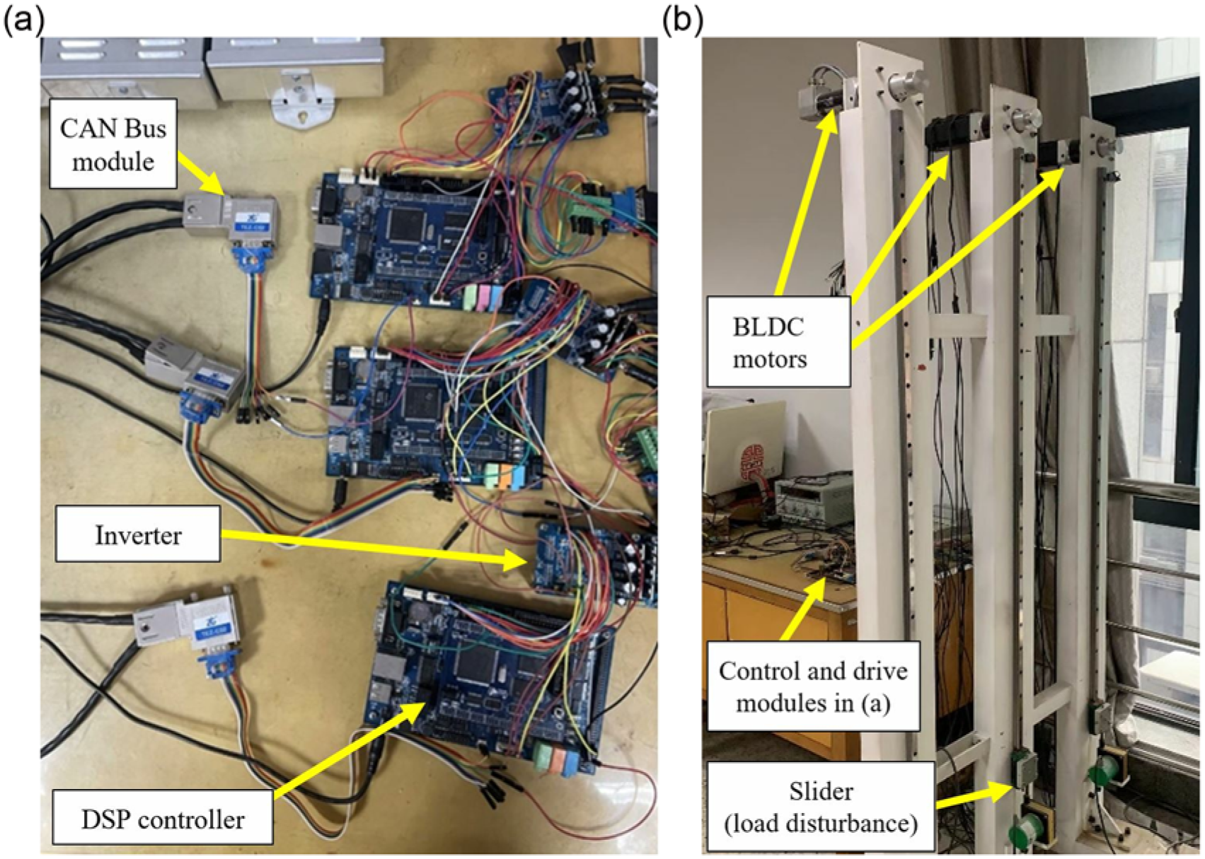
Experimental platform of triple BLDC motor synchronous control system: (a) control and drive modules and (b) experimental platform.
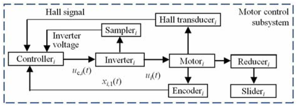
Schematic of motor control subsystem (i = 1,2,3).
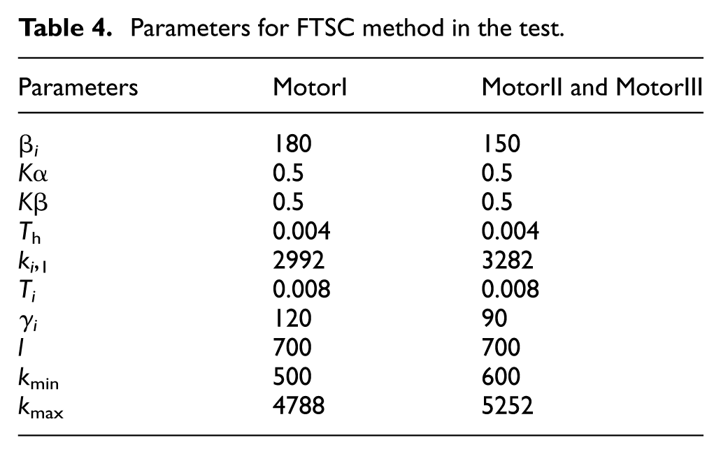
The system was running with the command speed 50 rad/s and the fixed load torque 4 Nm exerted on the reducer plus gradual variation along the sliderail motion for each motor subsystem. In comparison, four control methods, the synchronous method without FTC, the ACC method, the SMFTC method and the proposed FTSC method, were applied in the test. For the first two methods, control parameters KP = 0.31 and KI = 15.11 for MotorI, KP = 0.19 and KI = 12.15 for MotorII and MotorIII were designed for the optimal PI control, and Kα = 0.5, Kβ = 0.5 for synchronous compensation among motors. For SMFTC method, parameters in control law (30) were h i = 0.03, ρ i = 19, c1 = 62 and c2 = 212 for MotorI; h i = 0.021, ρ i = 10, c1 = 5 and c2 = 27 for MotorII and MotorIII. The designed parameters are listed in Table 4 for FTSC method. The real-time performance of the above FTC strategies was constrained by the hardware performance of the experimental system, the CAN communication speed, the multi-tasking management of the μcos-II system, and the C programing techniques. To improve the computational efficiency of the control algorithms, we employed the DSP chip (TMS320F28335) running at a high clock frequency of 150 MHz and adopted the incremental PID algorithm. In programing the control algorithms, all calculus-based operations were also converted into algebraic operations, with multiplication and division being the most time-consuming (each requiring 48 clock cycles). Considering the time required for CAN communication and for parameter conversion/estimation of motion signals, the synchronous control period was set to 0.004 s in the experiments to ensure reliable synchronization of the three-motor system. Based on the experimental measurements, the execution time within each synchronous control period were as follows: less than 0.0012 s for the PID algorithm, less than 0.00304 s for the SMFTC algorithm, and less than 0.00348 s for the proposed FTSC algorithm. The inverter fault was injected into MotorI at t = 6.16 s, which led the bus DC voltage decreased from 24 to 15.2 V (see Figure 10). It was perceived at 6.31 s by the M-SPRT technique and spent 0.15s to get the fault information. Figure 11 shows the speed response curves by four methods. It is evident that the synchronous errors were greater than 4 rad/s by the synchronous method without FTC and beyond the desired synchronization in the fault case. It can also be found that three FTC methods cannot eliminate the tracking errors, but compensate coordinately the speed variations to maintain the high synchronous precision in priority. It is very important in the actual processes such as the satellite antenna pointing operation and the delivery by space manipulators.
Parameters for FTSC method in the test.
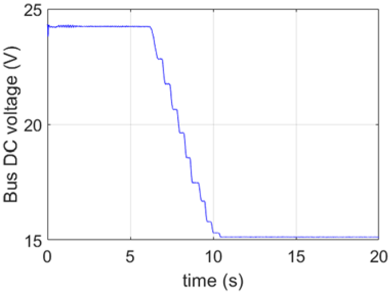
Bus DC voltage curve in the inverter of MotorI.
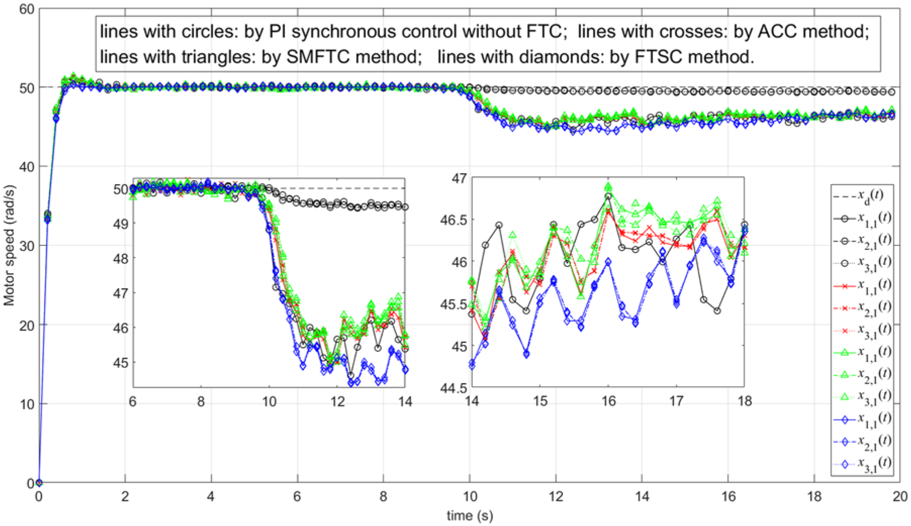
Speed curves of three motors in the inverter fault case. (dashed line: command xd(t).).
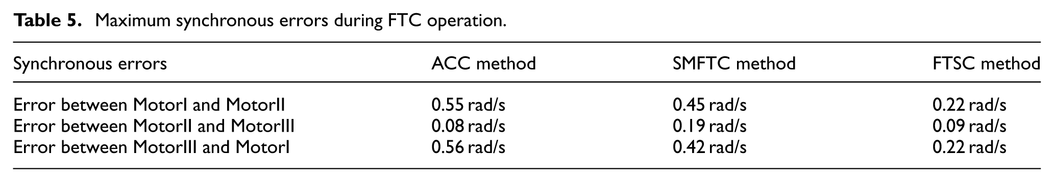
For the sake of comparing the performance among three FTC methods, the synchronous errors are shown in Figure 12 and Table 5. It is obvious that the synchronous errors by FTSC method were generally the smallest among three methods, while SMFTC method yielded the errors higher than FTSC method. The maximum errors were far less than the required value 0.8 rad/s by the proposed FTSC method, which kept the superior synchronization. Additionally, the maximum phase current of windings in the faulty MotorI by FTSC method was 4.25 A, far less than the nominal value 7.51 A during the FTC operation. It implied that the proposed FTC method also ensured the safety of the faulty system.
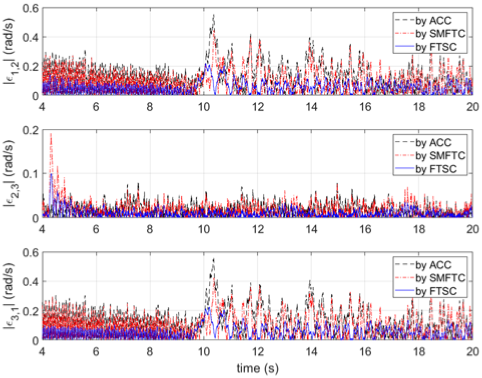
Synchronous errors in the inverter fault case. (|ε1,2|: between MotorI and MotorII; |ε2,3|: between MotorII and MotorIII; |ε3,1|: between MotorIII and MotorI.).
Maximum synchronous errors during FTC operation.
Conclusions
A fault-tolerant speed synchronous control strategy based on SC theory has been developed to tolerate the possible power inverter faults for the multi-motor systems with adjacent cross-coupling structure. By virtue of the coupling structure, only the fault detector and the SC-based coordinated FTC unit are attached to each motor subsystem. In the proposed SC-based coordinated FTC design, the manifold is devised by combining the synchronous error, the tracking error, and the angular acceleration. The corresponding weighting coefficients and control parameters are also determined by giving priority to the synchronization. The FTC system stability is further proven based on Lyapunov theory. Consequently, the resulted FTC method can timely adjust the manifold to maintain the desired synchronization in the inverter fault case. It can be readily extended to the position synchronization control and other coupled-based structures, which is one of the future topics. In addition, some control parameters in the strategy need to be tuned by prior knowledge. The process is cumbersome and techniques such as extremum-seeking algorithm 37 are worth investigating in future study to reduce the difficulty and improve the performance.
Footnotes
Appendix 1
The main procedures of fault detection by M-SPRT technique algorithm in Li 30 is presented here, which was used in this study.
where μ j is the mean value of the j-th alternative hypothesis, i = 1, 2, …, nA, and nA is the number of alternative hypothesis. μ j is usually preset according to the failure severity of inverter. In the experimental study, we set nA = 3 corresponding to the minor, middle and severe levels of the inverter failures, accordingly by 3%, 5%, and 10% of the nominal inverter voltage 15 V. Hence, the value of μ j is set by: μ1 = SPRT1 = 0.45, μ2 = SPRT2 = 0.75, μ3 = SPRT3 = 1.5. Then L j (k) can be obtained by (A2) and the residual signal u i f(k).
can be determined by Neyman-Pearson criterion. In our experimental study, the FAR and FNR are set by 2%, and th0 = −3.9, th1 = 3.9.
Ethical consideration
There is no ethical consideration because this work did not involve humans and animals. Ethics approval was not required for this research.
Consent to participate
Not applicable.
Consent for publication
Not applicable.
Funding
The authors disclosed receipt of the following financial support for the research, authorship, and/or publication of this article: This work was supported by the National Natural Science Foundation of China [grant number 62333010, 61972398, 61374133].
Declaration of conflicting interests
The authors declared no potential conflicts of interest with respect to the research, authorship, and/or publication of this article.
Data availability statement
Data sharing not applicable to this article as no datasets were generated or analyzed during the current study.