
Abstract
Multi-motor synchronous drive system is increasingly widely used in industry and manufacturing, where its control structure and control strategy affect the quality and efficiency of production. In order to solve the contradiction between fastness and overshoot, and the difficulty in determining the compensation law in the conventional PID, cross-coupling control, and master-slave control strategies used in multi-motor control, this paper proposes a self-coupling PID control strategy based on ring adjacent compensation to reduce the complexity of the control structure. Furthermore, this paper analyzes the self-coupling PID parameter tuning rules and establishes the control structure of the ring coupling strategy, and proves its validity mathematically. The simulation results verify that the proposed strategy provides a fast response speed, high control precision, good disturbance rejection, and synchronization performance.
Keywords
Introduction
With the development of modern industrial technology, the using of multi-motor synchronous control is increasing, such as electric cars,1,2 aerospace, and so on,3,4 especially for the high-precision high-speed systems, and cooperative control is the central issue.5,6 In China and abroad, the number of studies that focus on multi-motor synchronous control technology is growing more and more. However, the early synchronous control is primarily based on the mechanical connection, which is simple, but the accuracy of synchronization is low. 7 With the development of motor transmission technology, information technology, and automatic control technology, the synchronous mode of mechanical connection transmission has been replaced by an electrical servomotor.8,9 Currently, multi-motor cooperative control mainly comprises non-coupling control and coupling control. Where, the Non-coupling control includes master command control, master-slave control, and virtual axis control. Literatures10,11 is using master-slave control, and this scheme also has the problem of large-signal transmission delay; However, in literatures12,13 proposed virtual axis control, which realizes the synchronous control of multiple motors, but this control strategy has some problems such as given signal delay. Coupling control includes cross-coupling, adjacent coupling, deviation coupling, etc. In literatures14,15 the cross-coupling control was proposed. However, this scheme is suitable for dual-motor systems, but for multi-motor systems, the structure is complex and the compensation effect is not ideal. While, adjacent coupling control to overcome the defect that the cross-coupling structure is only suitable for double motors, but there are many synchronous error controllers and a large amount of computation was occurred; the deviation coupling control has high coupling degree, low control delay, and good synchronization ability, but the compensator is complex. Literature 16 proposes a data comparison method and a compensation algorithm, but the calculated amount is significant. Literature 17 proposes a synchronous control strategy that combines adjacent cross-coupled structures with sliding mode variable structure control, but each compensator requires many speed signals and has sliding mode jitter.
In order to improve the precision, stability, and robustness of cooperative control, a number of researchers have proposed different methods by combining modern control methods with existing control strategies. 18 In literatures19,20 the author presents sliding mode control, but there is sliding mode jitter; Literature 21 proposes adaptive neural network. However, there is a contradiction between control accuracy and parameter estimation; Literature 22 presents active disturbance rejection control, but there are many parameter tuning; Literature 23 proposes iterative learning control, but there is a problem with initial state selection; Literature 24 uses the fuzzy control algorithm to adjust the motor torque given value in real-time to improve the synchronization performance, but due to the simple fuzzy processing method, the useful information of the system is lost, and the dynamic tracking ability is very weak; Literature 25 proposes a variable domain fuzzy PID control based on a master-slave control structure. However, it involves multiple parameters, and the effectiveness relies on fuzzy rules. In literature, 26 a synchronization controller based on the mean relative coupling structure is proposed to address the coupling issue between synchronization and tracking. However, the synchronization compensation relies on the mean value.
In order to realize the cooperative control of multi-motors and ensure that each motor has good tracking, disturbance rejection, and synchronization in the operation process, based on the self-coupling PID control theory and deviation coupling control structure, this paper proposes self-coupling PID for multi-motor cooperative control based on circular adjacent compensation. The tracking and disturbance rejection of the system is improved by the self-coupling PID control, and the synchronization performance is improved by using the ring adjacent compensator. The self-coupling PID parameter tuning rules are analyzed, and the Lyapunov equation is established to analyze the stability of the compensation system. Finally, the numerical simulation test is used to verify the effectiveness of the control strategy.
The main contribution of this paper is to propose a self-coupled PID control strategy based on ring adjacent compensation for a multi-motor synchronous control system, as well as to develop a Romberg torque observer with minimal dependence on input information. The proposed ring compensation structure outperforms master-slave control, cross-coupling control, and virtual spindle control, providing new ideas for synchronous control problems.
Ring adjacent compensation control structure
The structure of the multi-motor synchronous control system based on ring-adjacent compensation is illustrated in Figure 1. In the system, each permanent magnet synchronous motor adopts the structure of a speed controller, current controller, and adjacent compensator. The current closed-loop adopts a vector control scheme of
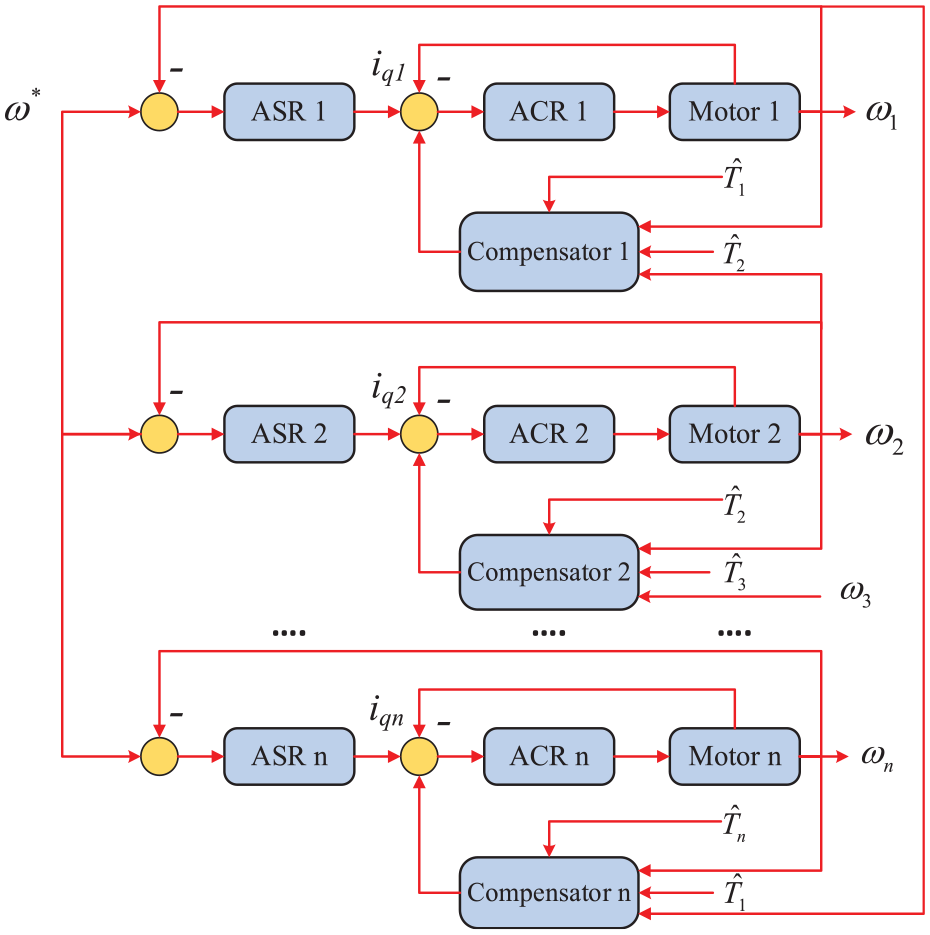
The structure of multi-motor synchronous control system with circular adjacent compensation.
The expected speed of each motor and each controller link in the system is same. The compensation amount of each compensation module is only related to the speed and a load torque of the two adjacent motors. The complexity of the compensator is independent of the motors number. The ring adjacent compensation control is more suitable for a multi-motor synchronous system in compared with the cross-coupling control strategy and the deviation coupling control strategy. In the
When the vector control
Where,
Design of multi-motor speed synchronization control
This paper mainly studies the design of the speed loop and the ring adjacent compensator of the permanent magnet synchronous motor, while the current loop adopts the conventional hysteresis control structure, which will not be repeated in this paper.
Design of self-coupling PID controller
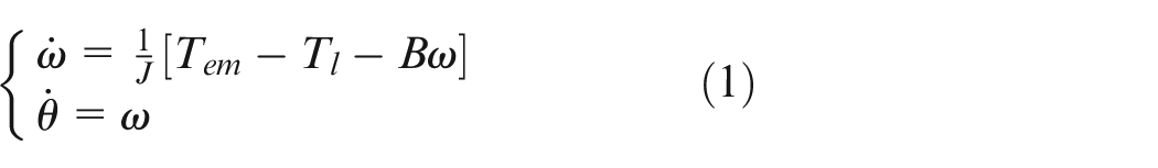
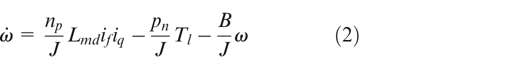
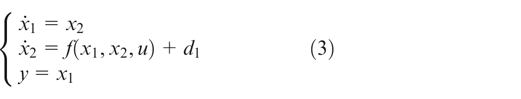
The speed-controlled object controlled by the current loop is a second-order system, and its affine nonlinear system is expressed as
Where,

where
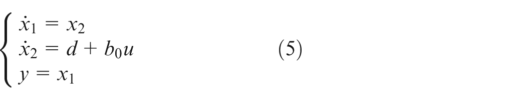
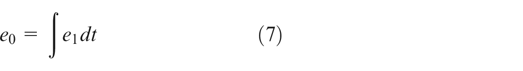
It can be seen from equation (5) that a class of non-affine nonlinear uncertain systems is transformed into a class of linear uncertain affine systems by introducing a comprehensive disturbance, and the control problem of the nonlinear uncertain system is transformed into the control problem of the linear uncertain affine system.27,28 For the system expressed by equation (3) or (5), the control error is defined as

The integral of error is
Then
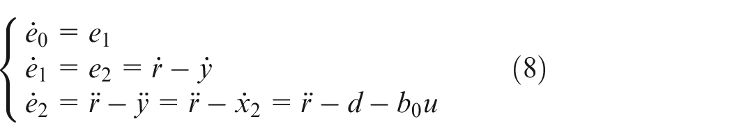
For the system expressed by equation (5), the auto-coupled PID control model29,30 is defined by equation (8) as

Then,
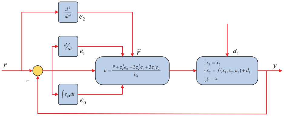
Closed-loop control system model based on self-coupled PID.
The main innovation of the strategy is that there is only a one-speed factor
Control system performance analysis
Theorem 1: Assuming that the sum disturbance defined by equation (4) is bounded:
Proving: Substitute the SC-PID controller defined by equation (9) into the controlled error system shown in equation (8) to obtain a closed-loop control system as
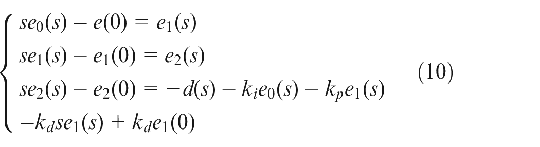
Since
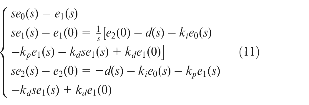
It can be obtained from equation (11) as
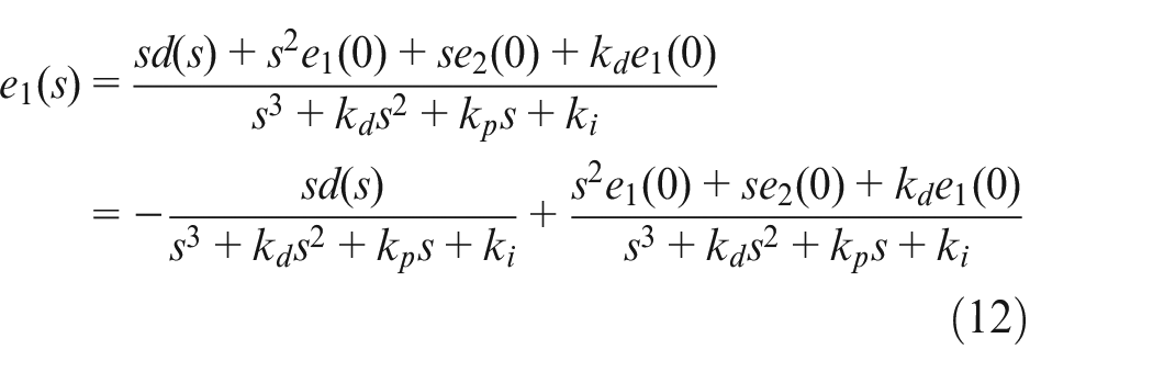
The first term is the zero-state response and the second term is the zero-input response. From equation (12), the transfer function of the closed-loop system can be obtained as
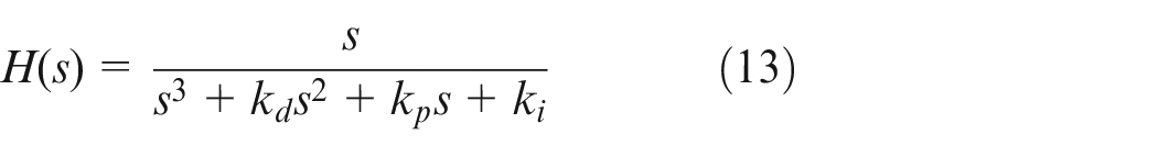
Let equation (13) have three identical real roots, three different real roots (namely

In addition, according to the principle that the zero-input response of the system has a fixed relationship with
Parameter tuning analysis
In order to stabilize the system, let the three roots be
If the three roots of the system are
Therefore, only by determining
If the three roots of the system are
Therefore, only by determining
If the three roots of the system are
The parameters of the controller can be determined only after confirming
Adjacent ring compensation control strategy
Let the synchronization error between the ith motor and the next motor be

Then the tracking error of the ith motor after being corrected by the compensation module is

According to the Lyapunov theorem, construct the Lyapunov function as
If

Therefore, the system is globally stable when

Assuming that all motor parameters are the same, that is,
As can be seen from the above, the torque
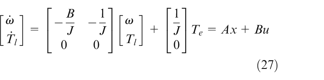
Design of load torque observer
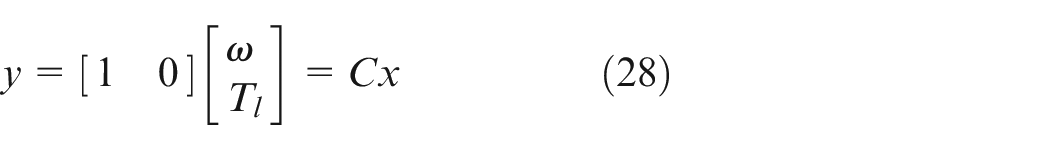
According to formula (1), the rotational speed can be measured, while the load torque cannot be measured. Select,
The form of the Luenberger observer is constructed as follows
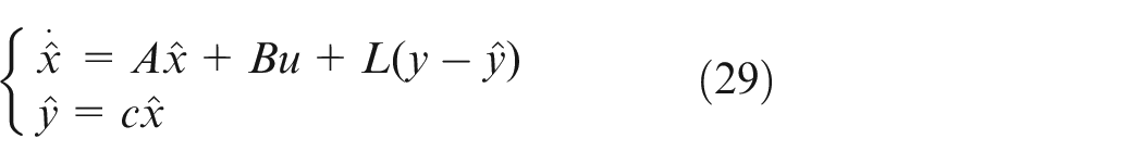
where

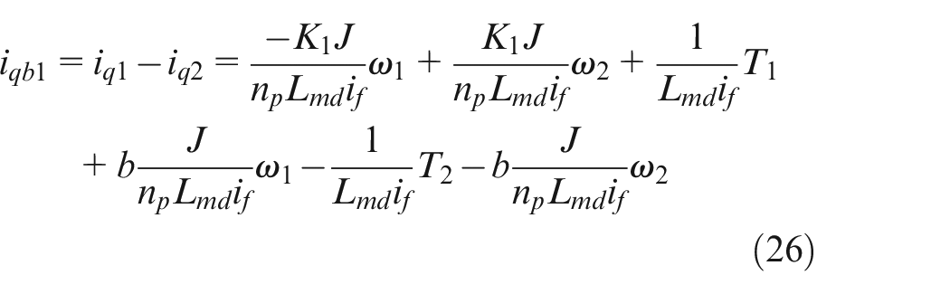
Substitute equations (27) and (28) into equation (30) to get
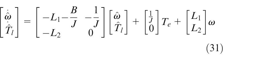
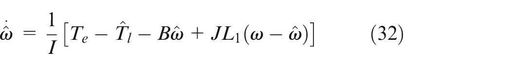
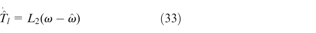
It can be seen from equation (33) that the load torque can be observed only by the electromagnetic torque of the motor and the actual speed of the motor without additional hardware equipment. The system control process is shown in Figure 3.
System control process.
Simulation and analysis
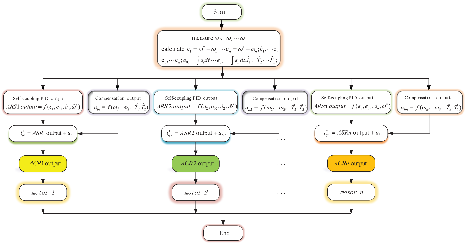
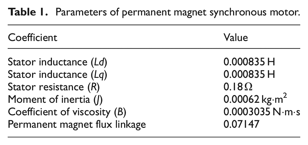
In order to further prove the correctness, stability, and effectiveness of the cooperative control scheme proposed in this study, a multi-motor synchronous control system composed of three motors is constructed and simulated on the MATLAB/Simulink platform. The three selected motors have the same parameters, as summarized in Table 1.
Parameters of permanent magnet synchronous motor.
Simulation of self-coupling PID and conventional PID
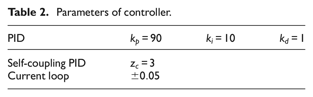
In order to verify the effect of the self-coupling PID control, compared with the conventional PID control, two control methods use the hysteresis controller in the current loop and the ring adjacent compensation. The controller parameters are summarized in Table 2. The expected speed value is
Parameters of controller.
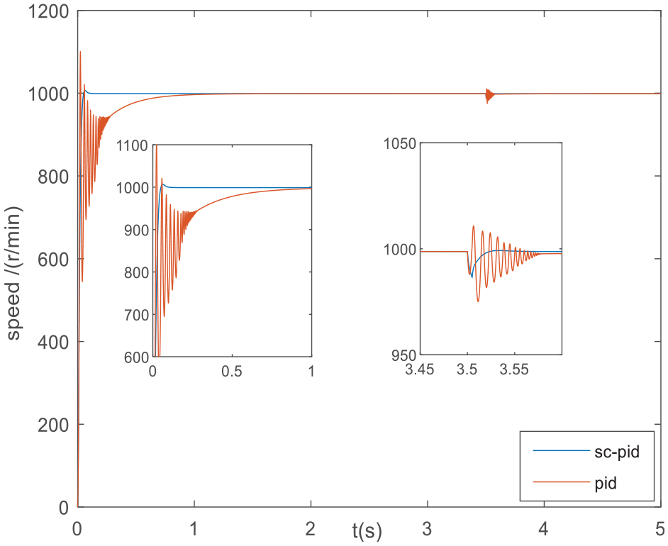
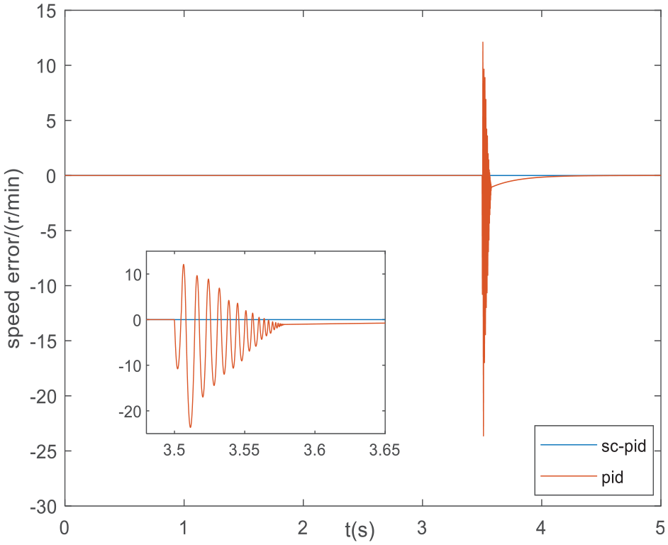
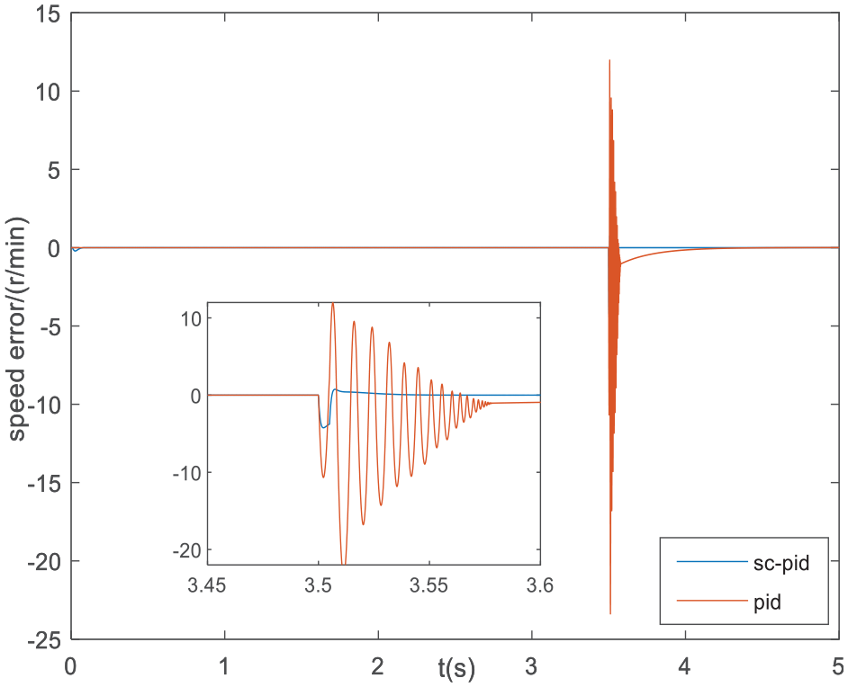
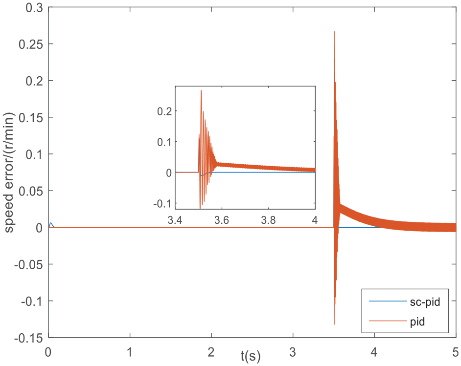
Self-coupling PID and PID control response curve.
Speed synchronization difference between motor 1 and motor 2 under the separate control of sc-pid and pid.
Speed synchronization difference between motor 2 and motor 3 under the separate control of sc-pid and pid.
Speed synchronization difference between motor 1 and motor 3 under the separate control of sc-pid and pid.
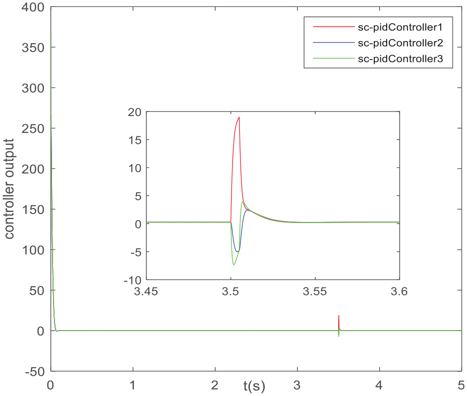
Each self-coupled PID controller output.
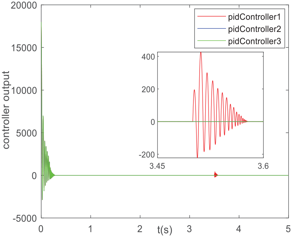
Each PID controller output.
It can be seen from Figure 4 that the overshoot of PID control is 10% and the adjustment time is 0.7 s during the startup process, while the overshoot of self-coupling PID is 1% and the adjustment time is 0.1 s. When the load disturbance occurs, the dynamic speed drop of PID control is
The simulation of master-slave control, cross-coupling control, and proposed control strategy
In order to verify the effectiveness of the adjacent ring compensation control strategy proposed in this paper, it is compared with the master-slave control and cross-coupling control. In the master-slave control strategy system, motor 1 is set as the main motor, and motor 2 and motor 3 are the slave motors. The expected speed of the three control strategies is
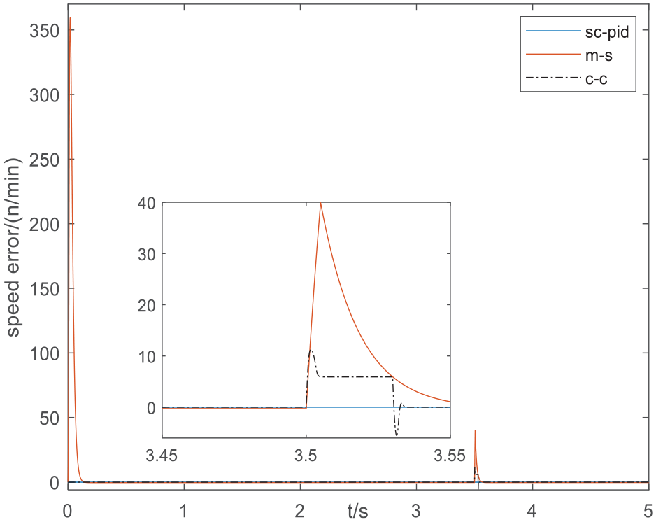
Speed synchronization difference between motor 1 and motor 2 under the separate control of sc-pid, m-s and c-c.
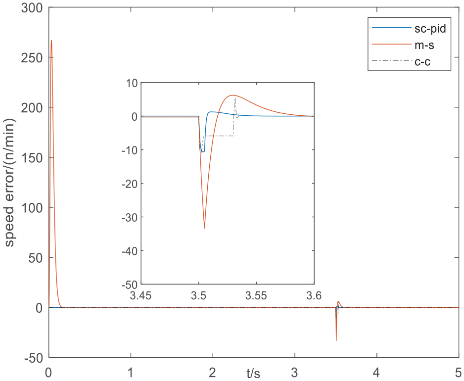
Speed synchronization difference between motor 2 and motor 3 under the separate control of sc-pid, m-s and c-c.
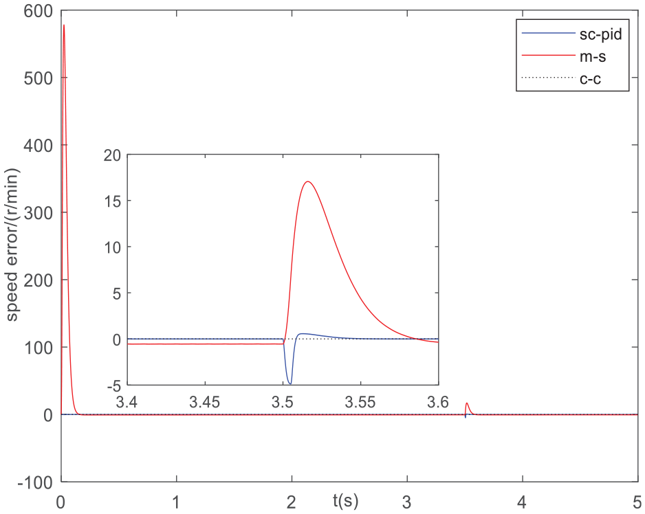
Speed synchronization difference between motor 1 and motor 3under the separate control of sc-pid, m-s and c-c.
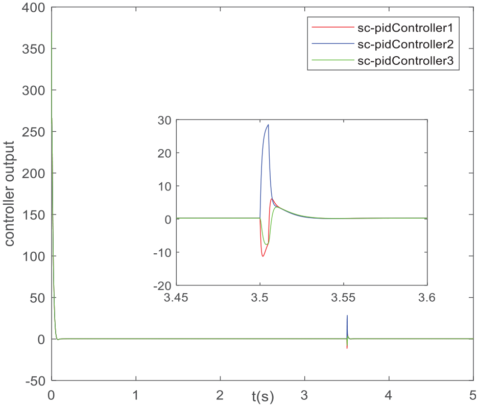
Output of each self-coupled PID controller.
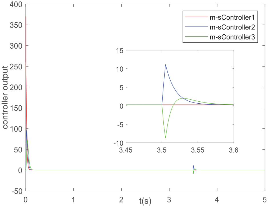
Output of each controller in master-slave mode.
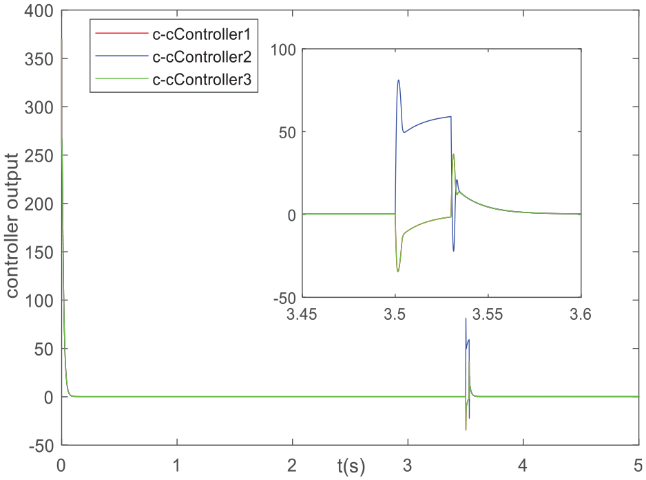
Output of each controller in cross-coupling mode.
It can be seen from Figures 10–12 that the synchronization errors of the three control strategies in the startup process finally tend to 0, and the synchronization errors of the adjacent ring compensation control and the cross-coupling control are 0, while the synchronization error of the master-slave control strategy is large, and the maximum speed synchronization error can reach
The load disturbance of the motor has a significant influence on the synchronous performance of the motor in the system using the master-slave control strategy, which needs 0.06–0.09 s to gradually converge to 0, and the cross-coupling control needs 0.035–0.04 s to gradually converge to 0; with the use of adjacent ring compensation control, the synchronization error between the disturbance motor and the adjacent two motors is less than that of the master-slave control and cross-coupling control strategy, and the synchronization error converges to 0 in 0.01–0.037 s and runs stably. Among them, the relative maximum synchronous speed deviation is
According to the simulation results of motor starting, when the system adopts the adjacent ring compensation control strategy, the motor synchronization error always approaches 0 and converges rapidly in the motor starting process, consequently, it has a good starting synchronization performance. The synchronous error caused by motor load disturbance is relatively small and converges rapidly, and its disturbance rejection is significantly better than that of the master-slave control strategy and cross-compensation control strategy. Based on the above analysis, it can be seen that the adjacent ring compensation control strategy significantly improves the dynamic and steady-state characteristics of the system, which shortens the disturbance recovery time, weakens the oscillation phenomenon, and offers good synchronization. In addition, the proposed control strategy has fewer controller parameters, simple parameter setting and small amount of system computation.
Conclusions
In order to solve the performance of multi-motor cooperative control, a self-coupling PID control structure with ring adjacent compensation is proposed to improve the synchronization, dynamic and static performance of the multi-motor system. The following conclusions are obtained through experiments:
1) In order to improve the synchronization of the multi-motor system, a new ring-adjacent compensation structure is proposed based on the coupling compensation principle. Where the complexity of the control structure can’t be affected by the number of motors;
2) In order to improve the system tracking and disturbance rejection, a self-coupled PID control strategy is used to analyze the system performance by pulse excitation response. The tuning rules of controller parameters are summarized by applying the relationship between roots and coefficients;
3) In order to achieve adjacent compensation, by constructing a Luenberger observer, the load torque can be observed only by the electromagnetic torque of the motor and the actual speed of the motor.
The convergence of the control algorithm is demonstrated by the use of the Lyapunov function. The proposed control strategy is applied to the synchronous control system of three motors and compared to the system using master-slave control and cross-coupling control strategy. The simulation results show that the proposed control strategy makes the system have good starting performance, dynamic performance, and disturbance rejection, and ensures the synchronization accuracy of the system, which is suitable for the synchronous control of multiple motors.
Footnotes
Declaration of conflicting interests
The author(s) declared no potential conflicts of interest with respect to the research, authorship, and/or publication of this article.
Funding
The author(s) disclosed receipt of the following financial support for the research, authorship, and/or publication of this article: This work was supported by the Science and Technology Research Project of the Education Department of Jilin Province [Grant JJKH20210042KJ], Jilin Provincial Development and Reform Commission Project [Grant 2019C058-1], the Jilin Province Vocational education research project [Grant 2021XHY248], and Graduate Innovation Program Project of Beihua University (Grant 2022006).