
Abstract
To address the wheel-lifting issue caused by the four-point highest-contact leveling strategy (FPHCLS), this study proposes a hybrid redundant leveling control strategy (HRLCS). First, a model of an emergency rescue vehicle was established and assembled in Matlab/Simulink/Simscape according to specific motion relationships, along with the construction of a hydraulic active suspension system. The vehicle model was then treated as a parallel mechanism, and the FPHCLS was applied to obtain the target displacement commands for the hydraulic actuators. A fuzzy PID controller was designed to ensure that three hydraulic actuators accurately tracked their target displacements, enabling the vehicle body to quickly level to the horizontal plane. Furthermore, inspired by compliant control in robotics, a force-displacement hybrid control was implemented for the right-front hydraulic actuator to maintain the desired pressure in the rodless chamber, ensuring continuous tire-ground contact during posture adjustment. Simulation results demonstrate that, when the vehicle traverses a single-side bridge obstacle and runs on a random road, the proposed HRLCS effectively reduces body pitch and roll motions. Compared with the passive suspension, the root mean square (RMS) values of the pitch and roll angles are reduced by 73% and 78%, respectively, when crossing the single-side bridge, while maintaining tire-ground contact at all times. On random roads, the RMS values of the pitch and roll angles are reduced by 61.2% and 43.4%, respectively.
Introduction
The emergency rescue vehicles are required to quickly transport rescue personnel and equipment to disaster sites. Generally, the roads in the rescue area are complex, and traveling on these roads can result in severe jolts and bumps. This not only causes secondary damage to the suspension but also impacts the precision instruments onboard. As a result, higher demands are placed on the vehicle’s ride comfort.1–3 However, most existing emergency rescue vehicles are equipped with passive suspensions. The rigidity and damping of passive suspensions are non-adjustable, making them unsuitable for varying road conditions, which leads to poor ride comfort.4–6
Driven by rapid advances in electronics and information technology, active suspension has become a feasible replacement for passive suspension. By continuously adjusting an onboard actuator, active suspension maintains the sprung-mass in a near-inertial state and thereby enhances ride performance. In the literature, vehicle motion is commonly modeled as a stochastic vibration process, and the resulting disturbances are attenuated a posteriori via control algorithms. Zhao and Gu 7 proposed a quarter-car model and devised an LQR controller whose weighting matrices were optimized by a hybrid particle swarm–genetic algorithm; numerical simulations demonstrated pronounced reductions in sprung-mass acceleration, suspension deflection, and dynamic tire load compared with both passive suspension and a conventionally tuned LQR active suspension. Li et al. 8 adopted the same quarter-car configuration and introduced a fractional-order PID (FOPID) scheme to overcome the imprecise parameter tuning inherent in classical PID control; the results indicated superior ride comfort relative to PID and fuzzy-PID counterparts. Amin et al. 9 constructed a seven-degree-of-freedom armored-vehicle model and employed skyhook control to improve ride quality under harsh off-road conditions. Wang et al. 10 applied optimal control theory to simultaneously mitigate vertical and roll motions of the vehicle body. Despite these achievements, the vehicle suspension system is an inherently nonlinear, multi-physics assembly; the majority of existing studies rely on simplified, often linearized, models that neglect key nonlinearities such as geometry-induced kinematics, friction, magnetic saturation, and actuator hysteresis, thereby limiting the attainable control performance.
To circumvent the adverse effects of structural nonlinearities on control performance, researchers have recently employed exteroceptive sensors (LiDAR and cameras) to acquire preview information of the upcoming road profile and adaptively reconfigure the suspension parameters in advance, thereby attenuating body vibrations. Yang et al. 11 developed a continuous multi-scan recursive matching algorithm for a single-line LiDAR that fuses height and pitch-angle offsets, yielding an accurate road-elevation estimate; simulations demonstrated that proactive damper adjustment based on this preview information markedly improved ride comfort and stability. Gong et al. 12 integrated LiDAR with GNSS and an inertial navigation system to generate 3-D point-cloud representations of the terrain ahead, which were subsequently filtered by statistical outlier-removal techniques in the point-cloud library to ensure high fidelity. Liu et al. 13 constructed a real-time forward-looking terrain model from LiDAR data and directly embedded it as a feed-forward input to an active suspension controller. Wang et al. 14 proposed a robust and accurate terrain-preview detection and classification framework that synergizes vision and LiDAR data through deep learning, effectively mitigating elevation errors caused by cumulative multi-sensor fusion drift. Hu et al. 15 introduced a camera-based preview control scheme for semi-active suspensions in which YOLO v2 detects speed bumps; an improved Skyhook policy then modulates the vertical damping force in real time. Simulations showed that the vision-assisted preview strategy enables anticipatory damping adjustment and hence significant ride-comfort gains. Nevertheless, the efficacy of such preview control degrades rapidly under adverse weather, high vehicle speeds, or limited computational throughput. Moreover, the high cost of these sensors currently restricts their deployment to luxury passenger cars and renders them unsuitable for emergency rescue vehicles.
In summary, vibration-suppression strategies rooted in sophisticated algorithms have improved suspension performance in silico, yet their stringent dependence on accurate mathematical models has largely confined them to theoretical studies and prevented widespread adoption in practice. Preview-control approaches that rely on exteroceptive sensors to acquire forthcoming terrain data are likewise hindered by adverse weather sensitivity and prohibitive cost, rendering them unsuitable for emergency-rescue platforms. As an alternative, recent investigations have focused on leveling-control strategies that regulate vehicle attitude without explicit road-preview or high-fidelity plant models. By treating the vehicle as a parallel mechanism, the inverse kinematics of the equivalent platform can be solved to determine the actuator displacements required to maintain a horizontal chassis. Guo et al. 16 proposed an active-suspension scheme for a multi-axle rescue vehicle modeled as a three-DOF parallel robot. Body attitude changes measured by an inertial measurement unit are translated into servo-actuator strokes, which are then commanded in closed-loop fashion. Experimental tests revealed that, compared with hydro-pneumatic suspensions, the proposed strategy not only stabilizes vehicle attitude but also attenuates body oscillations, markedly enhancing ride comfort and handling stability. Wang et al. 17 fused cylinder-pressure and biaxial tilt data to design a four-point leveling system for a load-carrying platform that tracks the highest-ground-contact principle. Results demonstrated that the achieved leveling accuracy and speed satisfy the operational requirements of transport vehicles. Pijuan et al. 18 developed an automatically height-adjustable suspension that improves mountain-driving safety and obstacle-negotiation capability. Zhang et al. 19 introduced a rapid, limited-range leveling/height-control algorithm; experiments confirmed that the vehicle promptly re-establishes its prescribed horizontal attitude and target height after disturbance. Collectively, leveling-control strategies derive actuator commands directly from measured body attitude and simple geometric relationships, offering low computational complexity and high efficiency. Nevertheless, during the leveling process wheel lift-off may occur; once a wheel loses contact, the vehicle can become prone to rollover under external perturbations.
During operation on uneven terrain, an emergency rescue vehicle exhibits three rigid-body motions with respect to an earth-fixed frame: roll, pitch, and heave. Because the chassis is supported by four independently actuated hydraulic cylinders, the suspension is kinematically over-actuated (four support points vs three degrees of freedom required for leveling). Consequently, conventional FPHCLS inevitably causes at least one wheel to lose ground contact. To reconcile ride comfort with persistent tire–ground interaction, This paper propose the HRLCS inspired by robotic compliance control. The left-front, left-rear and right-rear cylinders track the displacement commands generated by the FPHCLS, thereby forming a statically determinate three-point support that regulates vehicle attitude. The right-front cylinder is decoupled from this leveling loop and instead operates in a force–position hybrid mode20–23: its rod-side chamber pressure is servo-maintained at a desired set-point by modulating its extension. This guarantees a prescribed contact force at the right-front wheel, eliminating lift-off. Simulation and field tests demonstrate that the hybrid redundant scheme retains the superior leveling performance of the conventional method while ensuring continuous tire–ground contact, thus enhancing both ride comfort and operational safety for emergency rescue missions.
The organization of this paper is as follows: Chapter 2 introduces the control principles of the hydraulically actuated active suspension. Chapter 3 presents the FPHCLS and, based on the force–displacement hybrid control concept, proposes the HRLCS. Chapter 4 establishes a model of an emergency rescue vehicle and simulates the vehicle’s body posture and tire contact forces when traversing obstacles under the redundant leveling control strategy.
The hydraulic active suspension system
The hydraulic schematic of this system appears in Figure 1. An electric motor five drives hydraulic pump 4 to draw fluid from reservoir 7. The solenoid directional valve 2 receives the signal from the controller, thereby controlling the movement of the valve spool. When solenoid directional valve 2 shifts to the left position pressurized oil flows into the rodless chamber of hydraulic cylinder 1 and pushes the piston rod downward. When the same valve shifts to the right position oil enters the rod side chamber and pulls the rod upward, thereby achieving extension and retraction. Accumulator 3 maintains the preset system pressure and compensates for any leakage induced pressure drop. Relief valve 6 limits the maximum system pressure to protect all hydraulic components from damage.
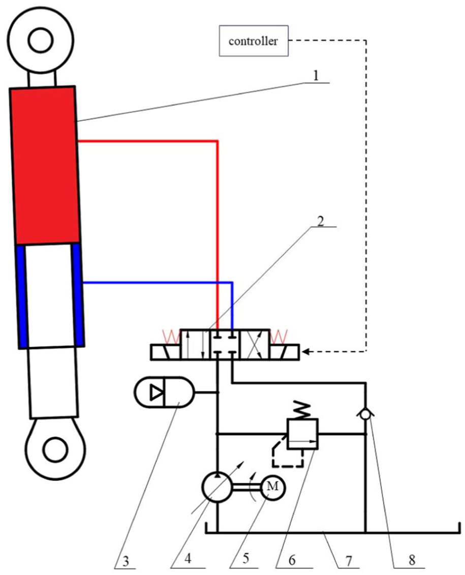
Working principle of hydraulic active suspension. 1. Hydraulic cylinder, 2. Solenoid directional valve, 3. Accumulator, 4. Hydraulic pump, 5. Electric motor, 6. Relief valve, 7. reservoir, 8. Check valve.
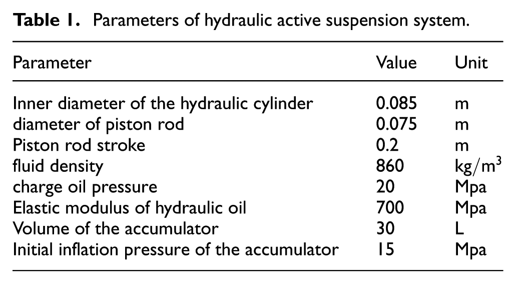
The pertinent physical parameters are listed in Table 1.
Parameters of hydraulic active suspension system.
Principle of vehicle body attitude leveling
Principle of FPHCLS
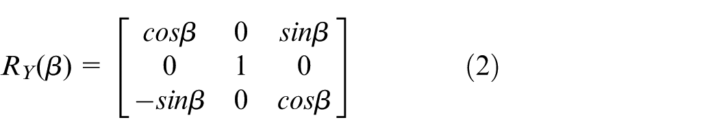
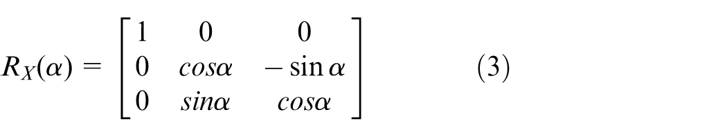
The emergency rescue vehicle is not equipped with a conventional damping system; instead, its body attitude is regulated solely by the extension and retraction of four hydraulic cylinders. Let the Euler angles of the body platform be defined as a rotation of

Here,
As shown in Figure 2,
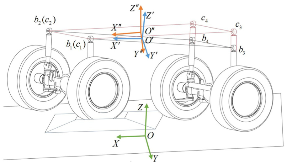
Principle of vehicle attitude adjustment.
Assuming the body platform is initially level, the initial coordinate system
Where
The vehicle body is supported at four points: A (front left), B (front right), C (rear left), and D (rear right). Based on the measured pitch and roll angles, the highest support point of the vehicle body can be identified:
Case1: When the roll angle
Case2: When the roll angle
Case3: When the roll angle
Case4: When the roll angle
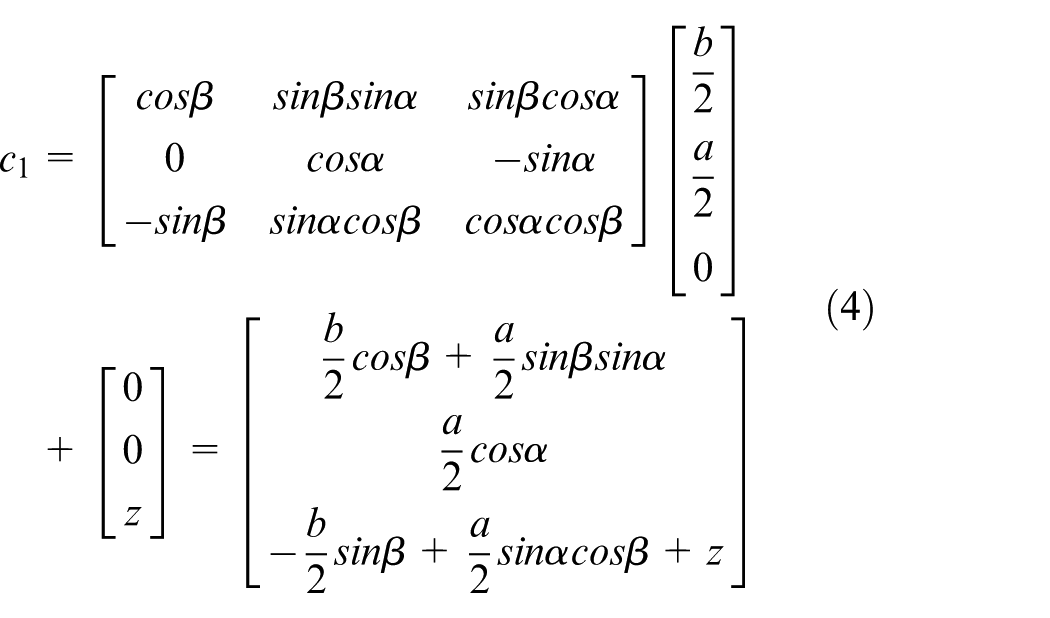
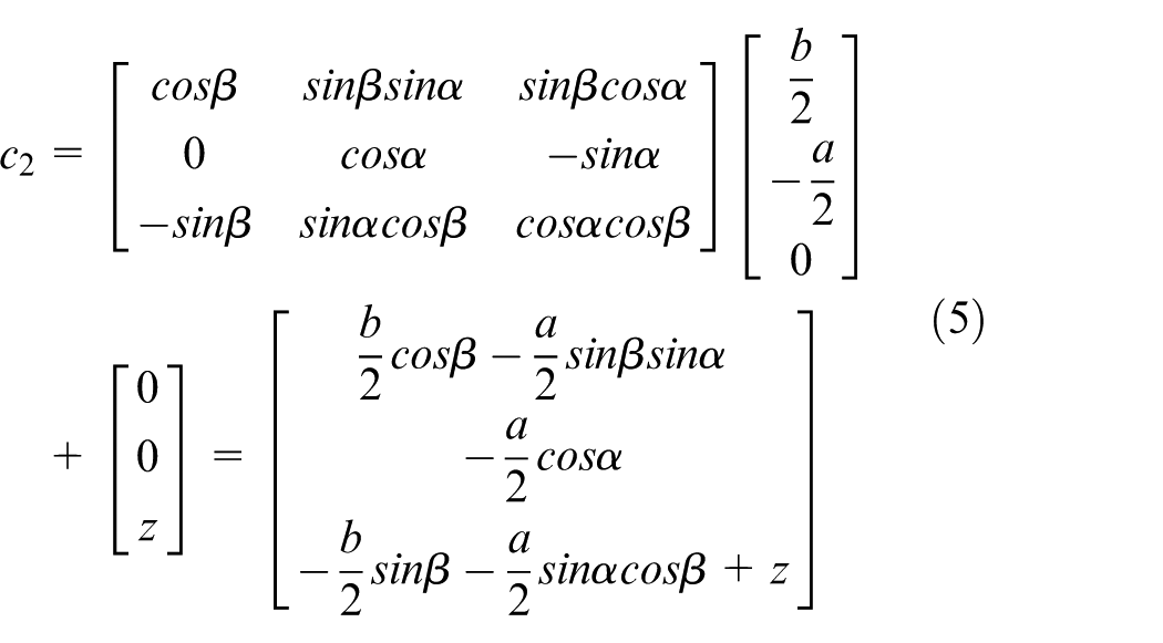
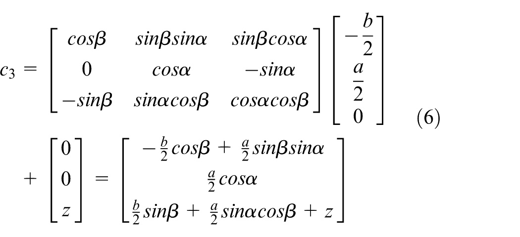
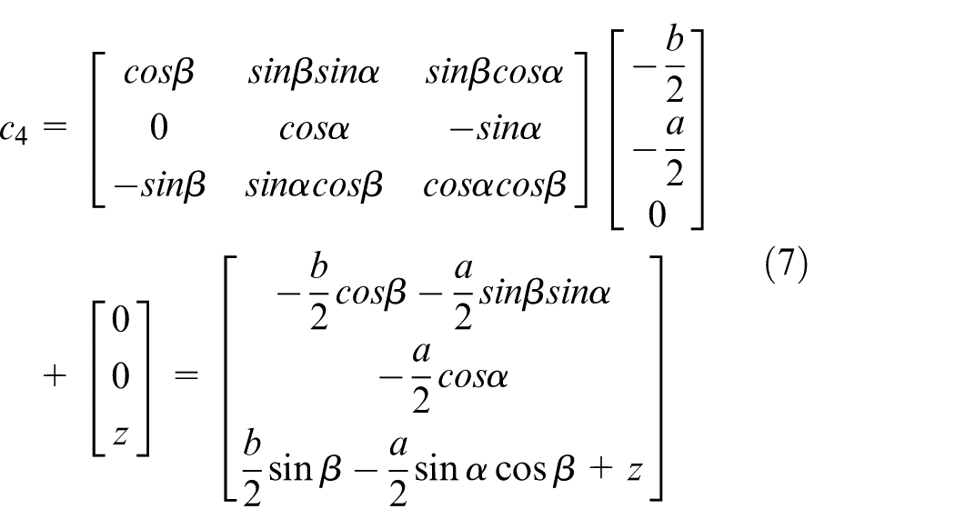
When support point A is identified as the highest, the required actuator strokes of the four hydraulic cylinders are calculated as follows:
where
If support point B is the highest, the required actuator strokes of the four hydraulic cylinders are as follows:
If support point C is the highest, the required actuator strokes of the four hydraulic cylinders are as follows:
If support point D is the highest, the required actuator strokes of the four hydraulic cylinders are as follows:
As three points uniquely define a plane, employing four support points for vehicle body leveling may result in wheel lift-off during the leveling process. To address this issue, the HRLCS is proposed in this paper.
Principle of HRLCS
To ensure continuous tire–ground contact, this paper proposes the HRLCS. The right-front hydraulic cylinder no longer follows the displacement command generated by the FHPCLS; instead, it operates under the HRLCS borrowed from robotic control. By extending or retracting the cylinder, the pressure in its rodless chamber is servo-maintained at the desired set-point. The displacement command for the right-front cylinder then becomes:
To ensure continuous contact between the tires and the ground, the HRLCS is proposed in this study. In this approach, the right-front hydraulic actuator no longer follows the displacement command generated by the FHPCLS. Instead, it operates according to the HRLCS derived from robotic control theory. By extending or retracting the hydraulic rod, the pressure within the rodless chamber is servo-regulated to maintain a preset value. Consequently, the displacement command of the right-front actuator is expressed as:
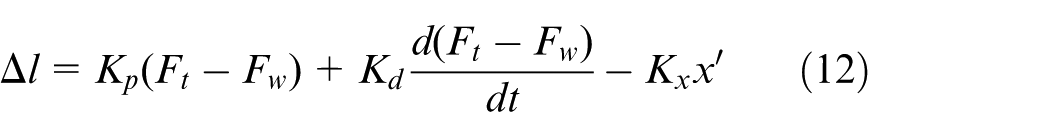
where
The force–position control principle is illustrated in Figure 3.
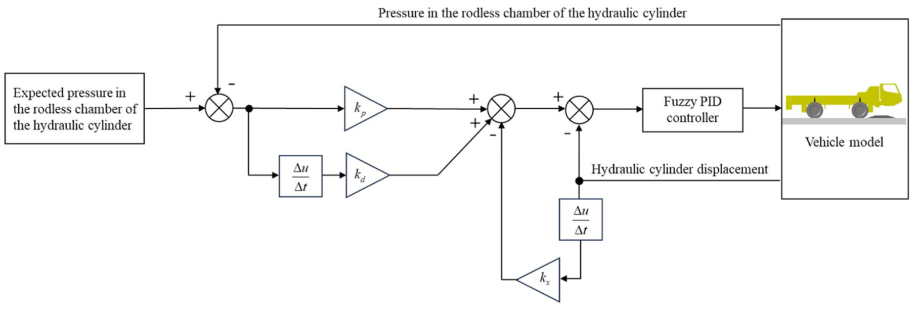
Principle of force–position control.
The left-front, left-rear, and right-rear hydraulic cylinders track the displacement commands generated by the FPHCLS; these three cylinders adjust the body attitude to keep the platform as level as possible.
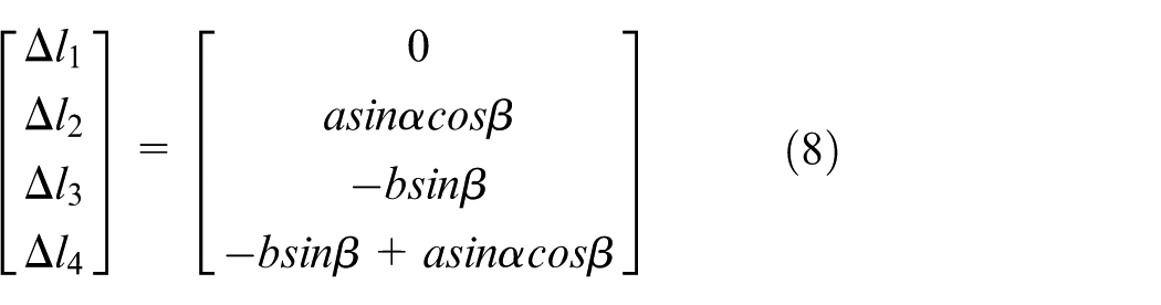
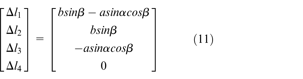
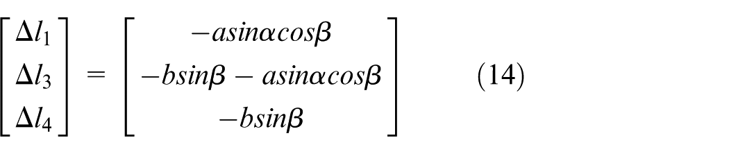
When support point A is identified as the highest, the displacement commands to be tracked by the left-front, left-rear, and right-rear hydraulic cylinders are respectively given by:
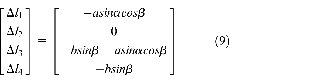
When support point B is identified as the highest, the displacement commands to be tracked by the left-front, left-rear, and right-rear hydraulic cylinders are respectively given by:
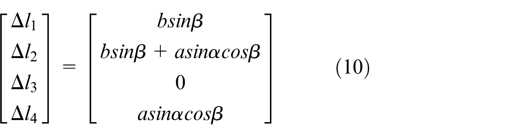
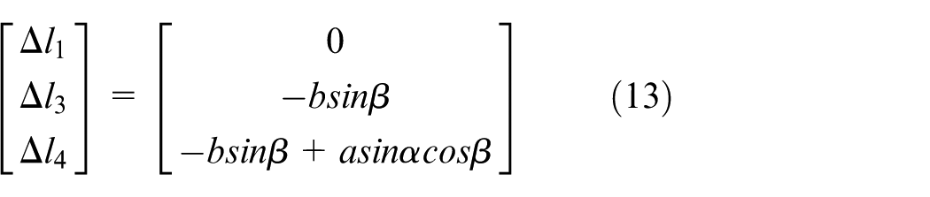
When support point C is identified as the highest, the displacement commands to be tracked by the left-front, left-rear, and right-rear hydraulic cylinders are respectively given by:
When support point D is identified as the highest, the displacement commands to be tracked by the left-front, left-rear, and right-rear hydraulic cylinders are respectively given by:

Simulation results and analysis
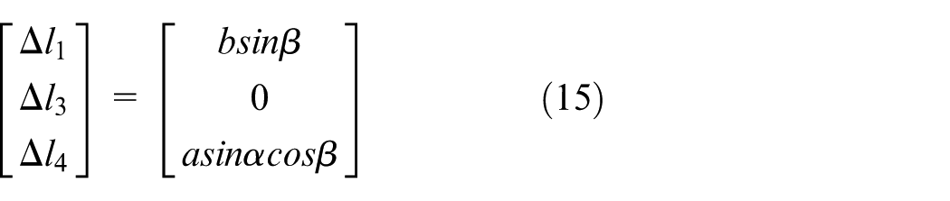
The emergency rescue vehicle model was constructed and assembled in MATLAB/Simulink/Simscape based on the prescribed kinematic relationships between components. A world coordinate system,
Vehicle assembly and hydraulic system schematic: (a) vehicle model and coordinate system definition and (b) quarter-vehicle active suspension system.
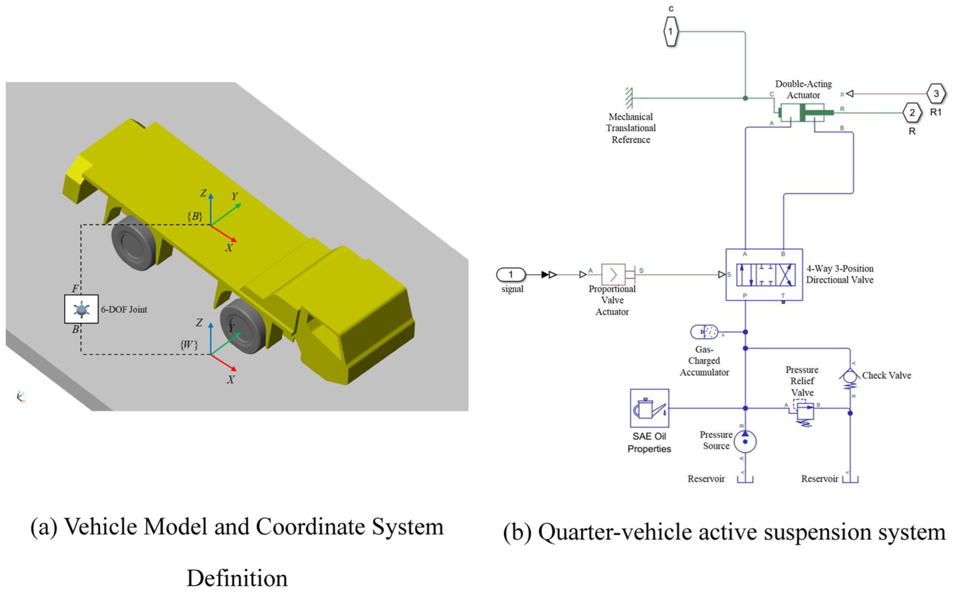
The fuzzy-PID strategy is adopted to ensure that each hydraulic cylinder accurately tracks the actuator displacement computed by the FPHCLS. The fuzzy controller employs position error
where
A triangular membership function is employed in this study, as illustrated in Figure 5.
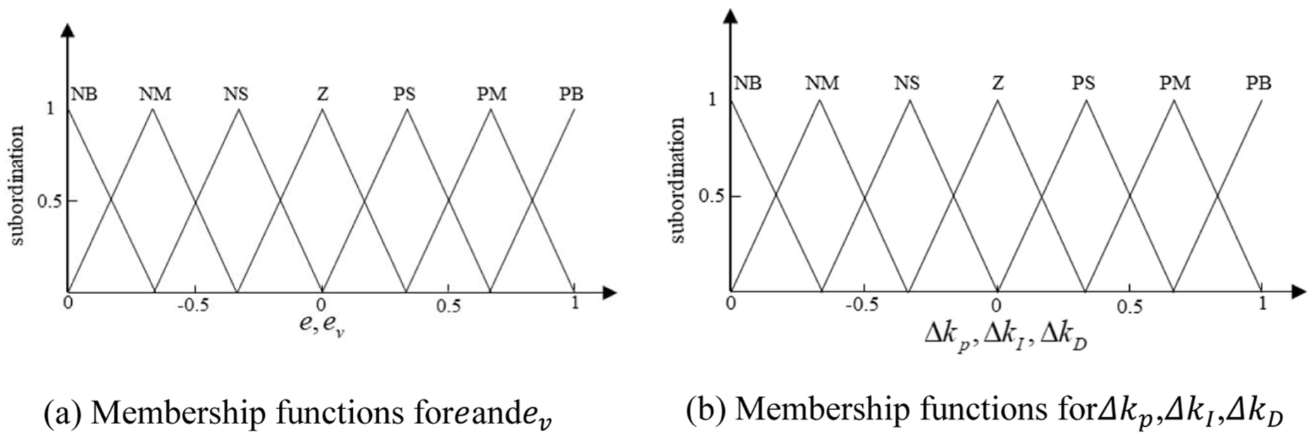
Membership functions: (a) membership functions for
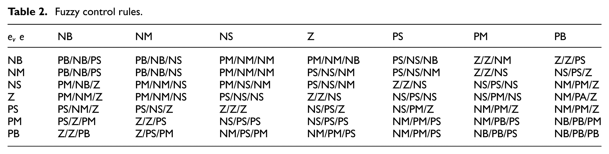
The fuzzy control rule base is given in Table 2.
Fuzzy control rules.
With the wheels rotating at 0.85
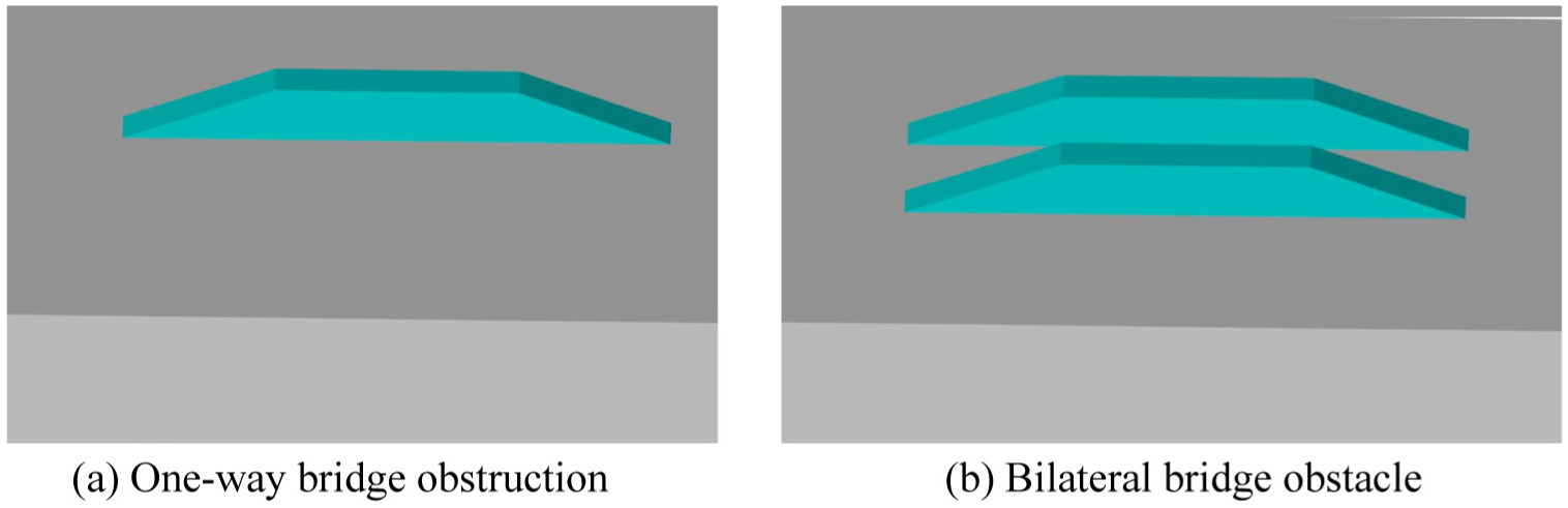
Road obstacles: (a) one-way bridge obstruction and (b) bilateral bridge obstacle.
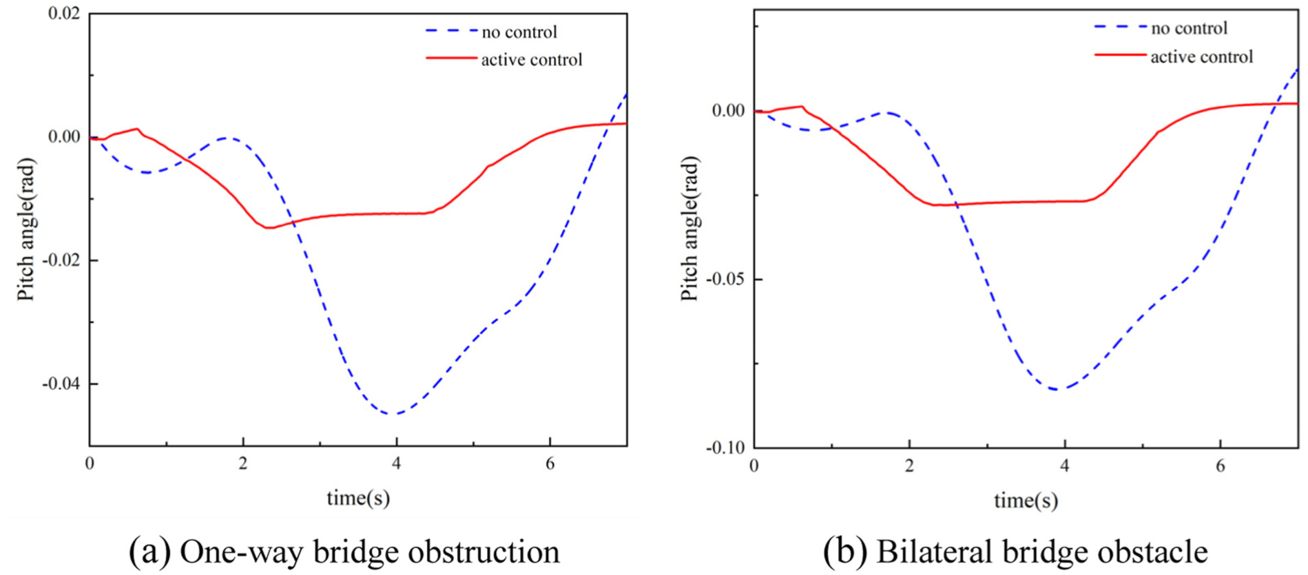
Changes in pitch angle of emergency rescue vehicles when passing through different obstacles: (a) one-way bridge obstruction and (b) bilateral bridge obstacle.
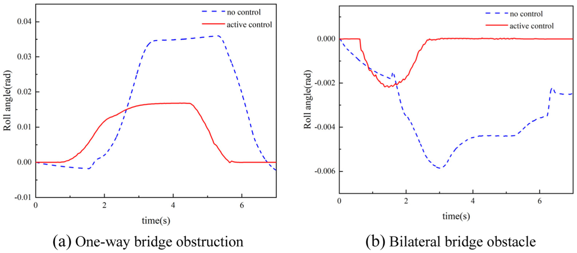
Changes in the side inclination angle of emergency rescue vehicles when passing through different obstacles: (a) one-way bridge obstruction and (b) bilateral bridge obstacle.
Figure 9 shows that, compared with the passive suspension, the proposed leveling control reduces the RMS pitch angle by 55.5% and the RMS roll angle by 41.1% when the emergency rescue vehicle negotiates the single-side bridge obstacle, and by 62.5% and 80.3% respectively for the double-side bridge obstacle.
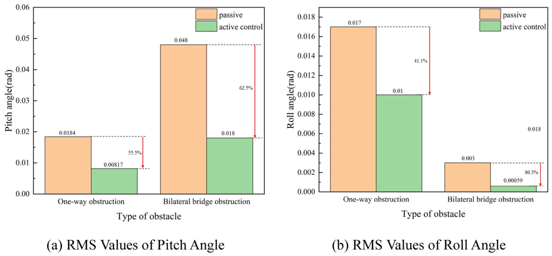
RMS value comparison: (a) RMS values of pitch angle and (b) RMS values of roll angle.
Figure 10 shows that the fuzzy-PID control strategy tracks the target displacement accurately.
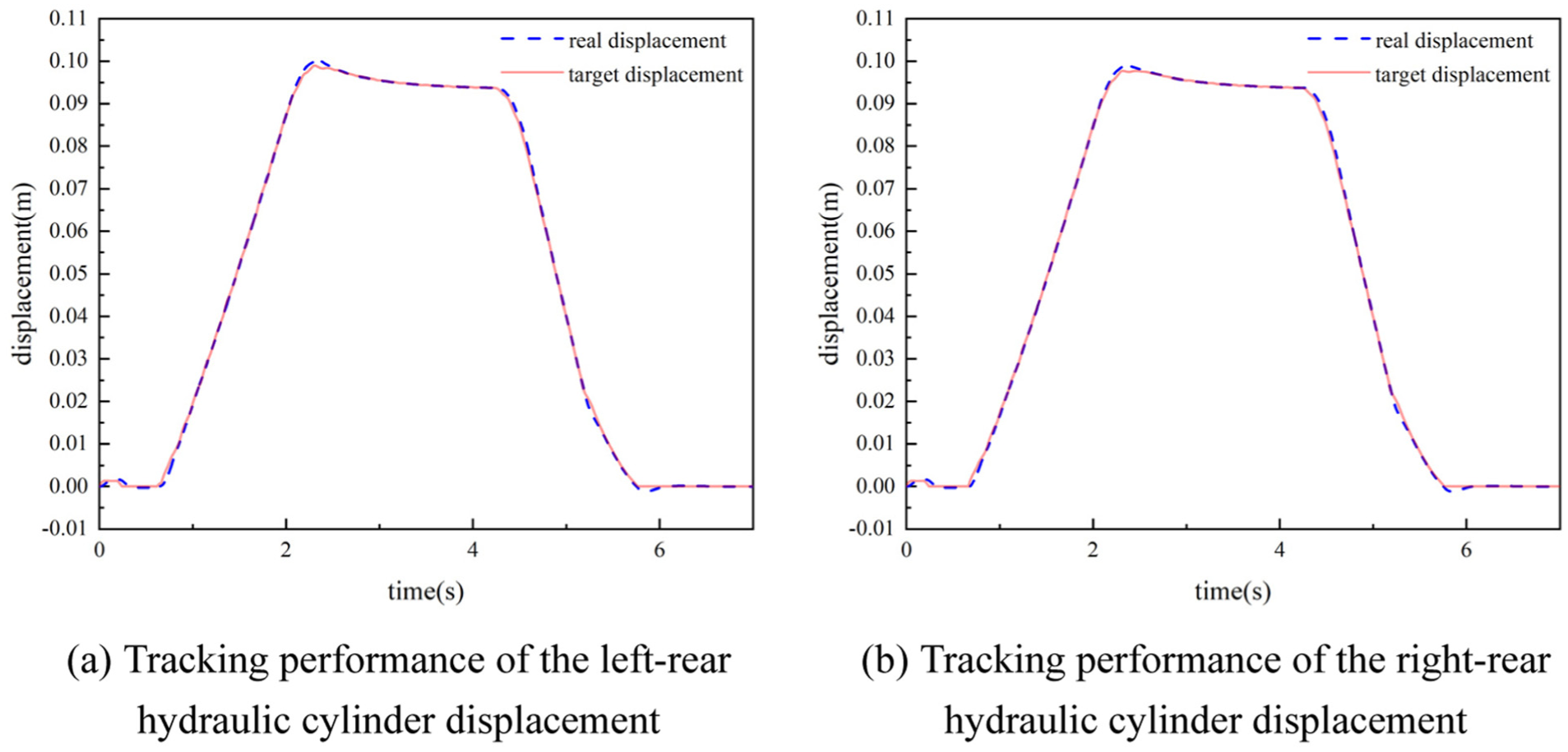
Hydraulic cylinder displacement tracking performance: (a) tracking performance of the left-rear hydraulic cylinder displacement and (b) tracking performance of the right-rear hydraulic cylinder displacement.
Figure 11 presents a sequence captured while the rescue vehicle traverses the single-side bridge obstacle. During leveling, the FPHCLS successfully attenuates both pitch and roll, yet it inevitably lifts one wheel off the ground. Once contact is lost, the platform is free to rock about the edge of the remaining three-leg support triangle, and under external disturbances such as wind gusts or equipment start-stop shocks the vehicle can even overturn.
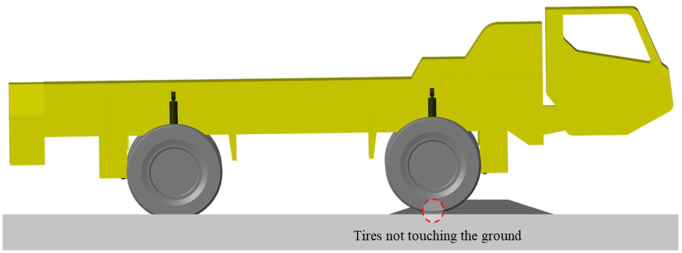
Snapshot of the emergency rescue vehicle negotiating a single-side bridge obstacle.
Similarly, when a 0.2 m-high obstacle is positioned ahead of the left-front wheel, the results in Figure 12 demonstrate that the proposed HRLCS significantly reduces both pitch and roll angles compared with the passive suspension during obstacle traversal.

Variation of pitch and roll angles when the vehicle traverses a single-sided bridge obstacle: (a) pitch angle and (b) roll angle.
To evaluate the general effectiveness of the proposed HRLCS, a random road profile was generated. As illustrated in Figure 13, the HRLCS demonstrates a clear reduction in both pitch and roll angles compared with the passive suspension when the vehicle travels over the random road surface.
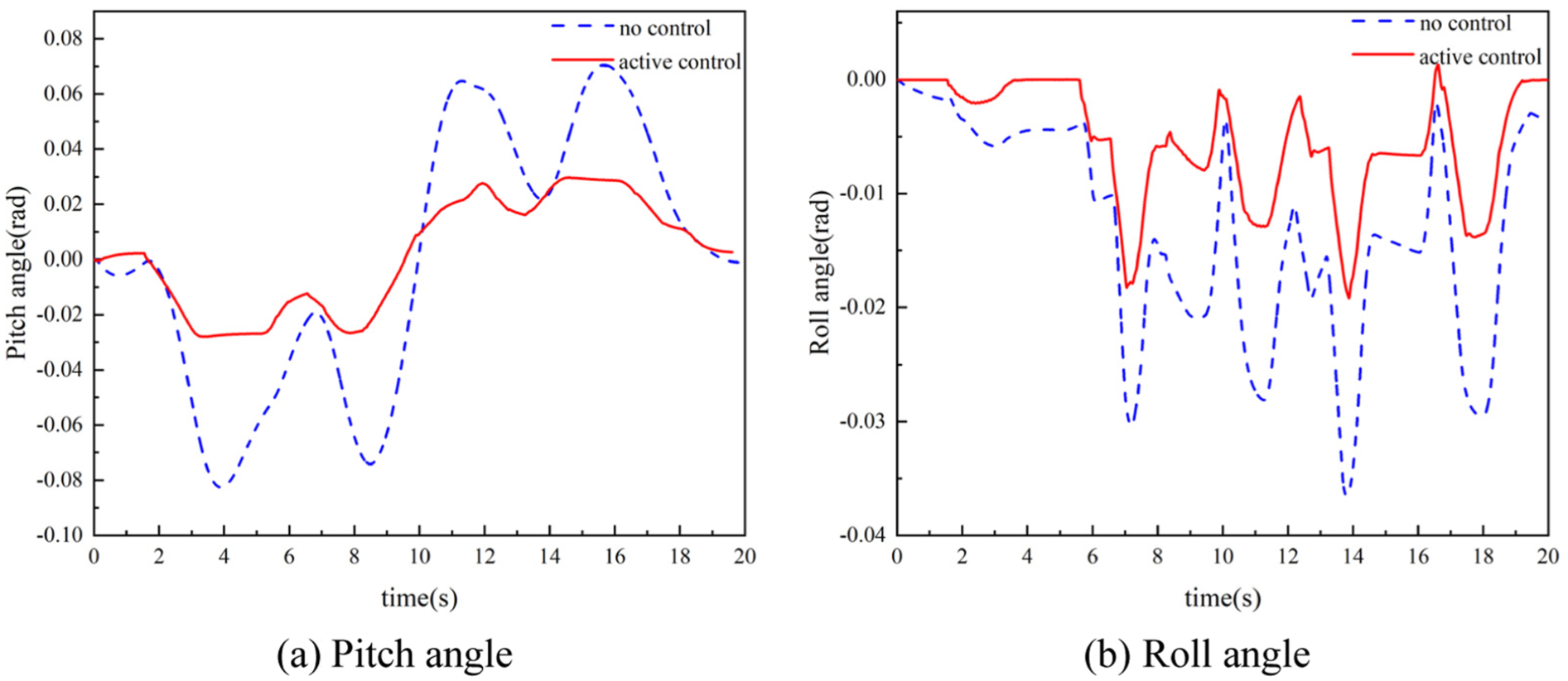
Variation of pitch and roll angles when the vehicle travels over the random road surface: (a) pitch angle and (b) roll angle.
Figure 14 indicates that, compared with the passive suspension, the RMS pitch angle is reduced by 61.2% and the RMS roll angle by 43.4% when the vehicle travels over the random road surface.
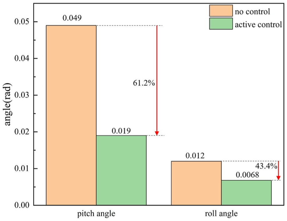
RMS comparison of pitch and roll angles.
Figure 15 displays the right-front wheel contact force during obstacle traversal. When the FPHCLS is employed, the contact force drops to zero between 1.81 and 4.1 s, confirming that the right-front wheel becomes airborne. By contrast, HRLCS maintains a strictly positive contact force throughout the maneuver, ensuring uninterrupted ground contact.
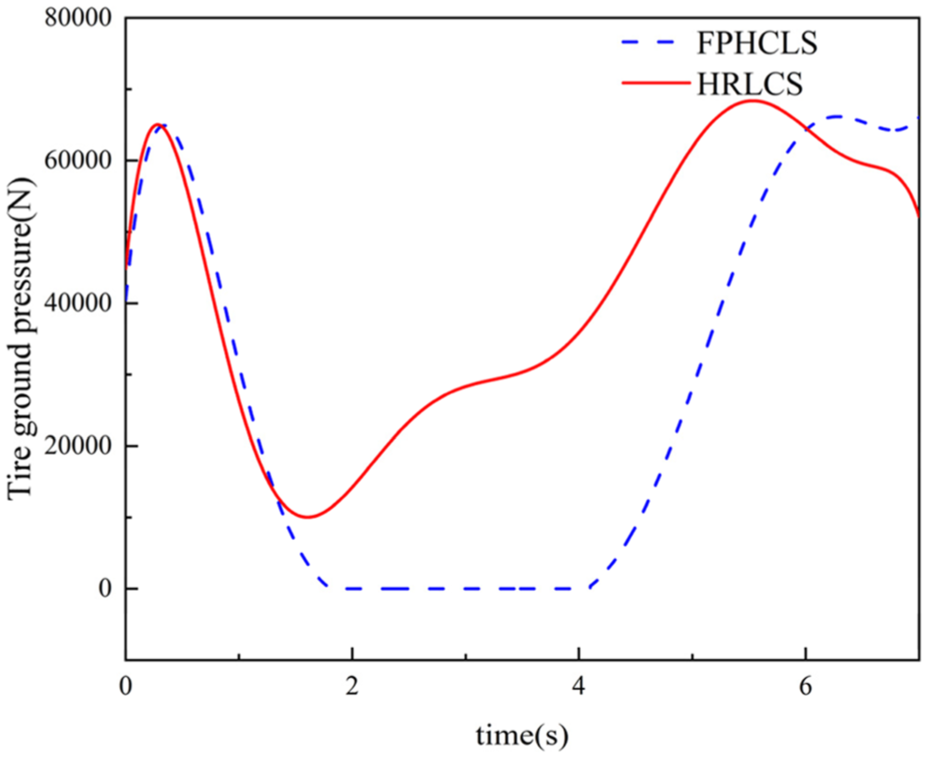
Right-front wheel contact force.
Discussion and conclusions
In this paper, the HRLCS is developed, employing a hybrid force–displacement control scheme to maintain the rodless chamber pressure of the right-front hydraulic actuator at a specified value. This strategy transforms the conventional four-point leveling into a three-point leveling mechanism, thereby addressing the wheel lift-off issue encountered in the Full Hydraulic Plane Compensation Leveling Strategy (FHPCLS) during vehicle body attitude regulation. The effectiveness of the HRLCS is validated through simulations, and the major research contributions are summarized as follows:
(1) The FPHPLS effectively reduces the vehicle’s pitch and roll angles during obstacle traversal. Compared with the passive suspension, it decreases these angles by 73% and 78%, respectively, when the vehicle negotiates a single-sided bridge. However, the FPHPLS inevitably causes one wheel to lift off the ground, thereby compromising the vehicle’s stability and safety.
(2) When a 0.2 m-high obstacle is positioned ahead of the left-front wheel, the results show that the proposed HRLCS effectively reduces the vehicle’s pitch and roll angles compared with the passive suspension. Furthermore, in contrast to the FHPCLS, the HRLCS successfully prevents the right-front wheel from leaving the ground during obstacle traversal.
(3) When the vehicle travels on a random road surface, the proposed HRLCS effectively reduces the pitch and roll angles by 61.2% and 43.4%, respectively, compared with the passive suspension.
Footnotes
Ethical considerations
This work does not involve ethical approval or consent. All authors confirm compliance with academic integrity standards in data analysis and result reporting.
Consent to participate
The informed consent form or patient consent form is not applicable to this work.
Trial registration number/date
The trial registration number/date is not applicable to this work.
Funding
The authors disclosed receipt of the following financial support for the research, authorship, and/or publication of this article: “This research was funded by Project supported by the Joint Funds of the National Natural Science Foundation of China, grant number U24A6008”.
Declaration of conflicting interests
The authors declared no potential conflicts of interest with respect to the research, authorship, and/or publication of this article.
Data availability statement
The data that support the findings of this study are available from the author, Ziqi Huang, upon reasonable request.