
Abstract
The new distribution network is an advanced power system built upon the traditional power network, which integrates distributed renewable energy sources, energy storage systems, and intelligent power electronic equipment. Unlike traditional distribution networks that only manage stable loads, the new distribution network faces dual challenges: the second-level power fluctuations from photovoltaics and the time-domain aggregation effects of electric vehicle charging loads. These factors lead to a high penetration of power electronics and increased system volatility, giving rise to significant power quality issues, including voltage fluctuations, violations of voltage limits, and three-phase imbalances. Existing on-load voltage regulators and reactive power compensation devices in the distribution network are insufficient to fully address these issues. In contrast, D-FACTS (Distribution Flexible Alternating Current Transmission System) devices have the potential to mitigate these problems and are increasingly recognized as an effective solution for power quality enhancement. This paper first reviews the power quality issues and mechanisms caused by the large-scale integration of photovoltaics and electric vehicles into the distribution network. Subsequently, it provides a detailed analysis on the topology and regulation principles of D-FACTS devices that can address these challenges. The paper also compares the performance of these devices and identifies the specific power quality problems each device can manage. Finally, based on future development needs, the paper proposes further research directions to provide theoretical foundations and practical guidance for the application and advancement of D-FACTS devices in the new distribution network.
Keywords
Introduction
The new distribution network represents an advanced evolution of the traditional power grid, characterized by the deep integration of distributed renewable energy sources, energy storage systems, and intelligent power electronic devices. A key distinguishing feature from traditional networks, which are designed for one-way power transmission and passive load management, is its support for bidirectional energy flow, enabled by an advanced topological structure and active regulation capabilities. Unlike traditional distribution networks, which only handle stable loads, the new distribution network faces dual challenges due to the integration of large-scale renewable energy and electric vehicles. Specifically, it is subject to second-scale power fluctuations from photovoltaics and wind power, as well as the time-domain aggregation effects of electric vehicle charging loads. Photovoltaic output can fluctuate by up to 30% of rated power per minute due to changes in irradiance, and electric vehicle cluster charging can create instantaneous demand equivalent to 120%–150% of regional distribution capacity during the evening peak period. The superposition of these two sources of uncertainty results in a system characterized by “double high” conditions (a high proportion of power electronic equipment and high volatility), rendering traditional regulation systems based on fixed compensation devices and mechanical voltage regulation completely ineffective.
The power quality issues arising from this exhibit three main characteristics: First, voltage fluctuations occur across multiple time and spatial scales. The combination of photovoltaic anti-peak regulation and EV charging causes daytime overvoltage and nighttime undervoltage amplitudes to reach ±15%. Second, there is a structural deficiency in reactive power support capacity. The reactive power regulation margin of distributed grid-connected inverters is less than 40% under low-load conditions. Third, three-phase imbalance worsens. When the penetration rate of single-phase EV charging stations exceeds 30%, the neutral line current can reach 1.8 times the phase current.
Traditional distribution networks typically rely on relatively simple dispatching and management methods. However, the increasing diversification of loads and the integration of distributed energy resources necessitate more flexible and efficient regulation technologies. Consequently, Distribution Flexible Alternating Current Transmission Systems (D-FACTS) have emerged as a key technology for effectively addressing power quality issues in modern distribution networks.
Traditional parallel D-FACTS devices, such as static synchronous compensators (D-STATCOM)1–4 and static VAR compensators (D-SVC),5–7 can continuously, smoothly, and flexibly compensate the power grid for reactive power, thereby adjusting both the amplitude and phase of the grid voltage. However, their voltage regulation capability is limited, restricting their effectiveness in certain scenarios. Additionally, some series flexible AC transmission devices, such as static synchronous series compensators (DSSC),8–10 can also compensate for both the amplitude and phase of the voltage. A key limitation of these series devices is that their DC side requires an additional energy source to achieve full compensation functionality. If only capacitors are used on the DC side, the device is limited to reactive power exchange, which falls short of comprehensive voltage amplitude and phase regulation requirements.
In comparison to conventional series and parallel regulation devices, phase-shifting transformers (PST)11–20 offer more flexibility in adjusting the phase of the grid voltage and have distinct advantages in power quality regulation within distribution networks. PSTs can be categorized into two types: conventional PSTs and special PSTs. Conventional PSTs can be further classified based on different criteria: according to output compensation voltage characteristics, they include longitudinal, transverse, and diagonal regulation PSTs; based on electrical characteristics, they comprise symmetrical and asymmetrical PSTs; and in terms of topological structure, they are divided into single-core and dual-core PSTs. Symmetrical PSTs alter only the voltage phase angle without affecting its amplitude, whereas asymmetrical PSTs can modify both.
Although conventional PSTs have limited capacity to change voltage amplitude, researchers have proposed special PSTs, such as Sen and Sen-type transformers (SPST).21–26 The SPST can simultaneously adjust both the voltage phase and amplitude, representing the most capable electromagnetic device currently available for power quality regulation in distribution networks. PSTs are generally recognized for their low cost, high efficiency, and ease of control.27–31 However, their disadvantages include the inability to continuously adjust both the amplitude and phase of the grid voltage and their relatively slow response times.
Devices capable of continuously regulating the voltage and phase of distribution networks are primarily based on power electronics technology, including Distribution Unified Power Flow Controllers (D-UPFC)32–38 and AC/DC hybrid flexible regulation devices.39–46 The chief advantage of these systems is their capability for continuous and rapid adjustment of voltage amplitude and phase, enabling them to effectively mitigate a wide range of power quality issues. However, the main disadvantage of such devices is their high cost, which limits their widespread adoption and application. To address this challenge, some researchers have combined the benefits of electromagnetic devices and power electronics and proposed hybrid flexible regulation devices for distribution networks.47,48
These devices integrate SPST with UPFC enabling not only continuous regulation of grid voltage and phase—thereby avoiding the issue of impact currents—but also reducing the capacity ratio of UPFC to mitigate the high cost. This hybrid solution is considered one of the more effective approaches for achieving power quality regulation in distribution networks.
This paper presents a comprehensive review of various D-FACTS devices and technologies applicable to power flow regulation in distribution networks.49–58 First, the impact of integrating large-scale distributed energy and diversified loads into distribution networks is analyzed to underscore the necessity and importance of power quality regulation. Second, various D-FACTS devices and technologies are analyzed and summarized.59–65 Finally, a comparative study of the existing D-FACTS devices is conducted from multiple perspectives, and the applicable scenarios for each device, along with the future development direction of power quality regulation technology in distribution networks, are discussed.
Mechanism analysis of power quality degradation in new distribution networks
Photovoltaic (PV) power generation exhibits high intermittency and uncertainty due to its dependence on solar irradiance and temperature.66–69 This variability poses significant challenges to grid dispatch, particularly during periods of uneven irradiance or abrupt weather changes, necessitating frequent adjustments to generation schedules and load-balancing strategies. These adjustments, in turn, impose complex impacts on both the generation side and the network infrastructure of the power system.
Additionally, the integration of electric vehicle (EV) charging stations, as a representative of new types of loads, also affects power quality. During peak hours in the morning, noon, and evening on weekdays, charging loads can reach 10%–15% of the local maximum load. Furthermore, due to the highly concentrated charging behavior of EV users, sudden large-scale charging demands—for instance, during holidays or special events—which place substantial stress on the grid and can trigger a range of power quality problems.
Impact of PV integration on power quality
Analysis of PV integration on voltage limit violations
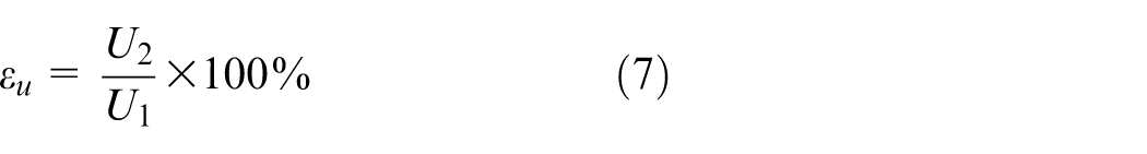
Voltage deviation is defined as the difference between a specific voltage measurement and the system’s nominal voltage, expressed as a percentage of the system’s nominal voltage, as shown in the formula:
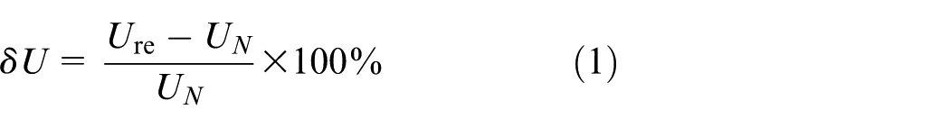
Where,
The integration of PV systems significantly affects voltage deviations, particularly in rural distribution networks, where most PV systems are connected at 400 V. This directly impacts voltage quality. According to the national power supply voltage standards introduced in 2003, the allowable voltage deviation for single-phase supply is +7% to −10%, meaning the voltage should remain within the range of 198–235.4 V.
When distributed PV is properly integrated into the distribution network, it can enhance voltage distribution to some extent. However, improper PV integration can alter power flow patterns, leading to voltage quality deterioration. Key factors influencing voltage quality include the location of PV integration, penetration level, and power factor.
A distribution network model with integrated distributed PV is illustrated in Figure 1. The network consists of
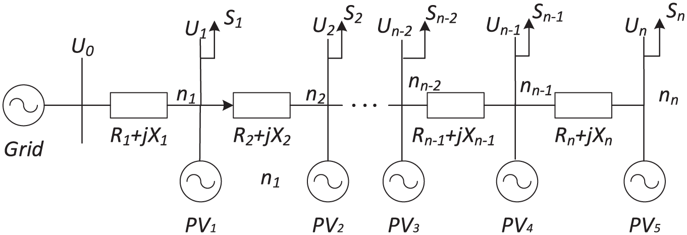
Single-feeder radial distribution network model with integrated distributed PV.
When a single distributed PV system is connected at node m, and assuming the reactive power of the PV system is negligible, the apparent power at node m can be expressed using the power flow equations as follows:
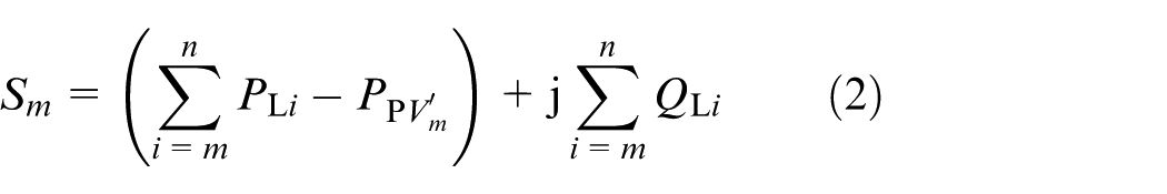
Where
Given that the rated voltage of the distribution feeder is
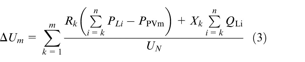
At this point, the voltage at node m is given by:
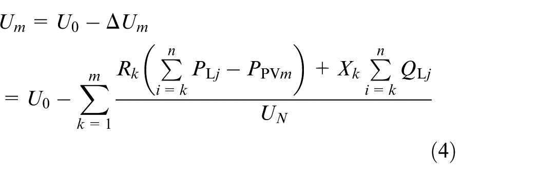
If the system has excessive capacitor compensation or if the power system load exhibits significant inductive reactive power, the line voltage drop
When the PV generation system encounters unforeseen conditions such as extreme weather events or equipment failures, leading to shutdowns or reductions in power output, the system’s overall power generation capacity suddenly decreases. According to equations (1) and (2), a reduction in
Impact analysis of grid-connected photovoltaic systems on voltage fluctuations
Since the Point of Common Coupling (PCC) is typically the node most significantly affected by photovoltaic (PV) power sources, the PCC node is selected as the research subject to analyze the influence of PV grid-connection on voltage fluctuations. The Thevenin equivalent circuit of the distribution network incorporating distributed PV is illustrated in Figure 2.
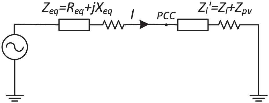
Thevenin equivalent circuit of distribution network with distributed photovoltaic systems.
Taking the voltage variation analysis at the photovoltaic grid-connected Point of Common Coupling (PCC) as an example, the integration of PV systems modifies the power flow into the load side of the distribution line, which manifests as a line current variation ΔI. The voltage fluctuation at PCC caused by PV power variations can be expressed as:
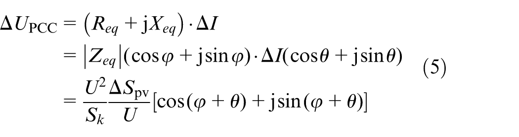
Where,
Low-voltage distribution lines are typically short in length, resulting in a minimal phase angle difference between the two ends of the feeder. Consequently, in calculations, the vertical component of
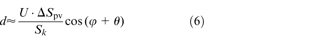
Based on equation (6), the following conclusions can be drawn:
(1) The output power of the PV system connected to the distribution network has a direct impact on voltage fluctuations. Instantaneous variations in PV generation, such as those caused by cloud cover, lead to sudden changes in output power, thereby causing significant voltage fluctuations.
(2) The higher the short-circuit capacity of the distribution network, the smaller the impact of PV integration on voltage fluctuations. In low-voltage distribution networks, due to their relatively low short-circuit capacity, PV integration has a more pronounced effect on voltage fluctuations.
Analysis of PV integration on three-phase imbalance
In distribution networks, a large number of asymmetric loads and three-phase asymmetries in line parameters exist. When operating under three-phase unbalanced conditions, the system voltage contains negative-sequence components, increasing equipment losses. The three-phase voltage imbalance is defined as the ratio of the root mean square (RMS) value of the negative-sequence component to the positive-sequence component, expressed as:
Distributed PV integration exacerbates the three-phase imbalance in the distribution network in three ways:
(1) Distributed PV systems may experience asymmetric faults, leading to accidental three-phase imbalance issues in the distribution network.
(2) Under normal operation, the PV system may not achieve its optimal working state due to imbalances in three-phase power output or asymmetries in the structural parameters of grid-connected inverters.
(3) Many residential loads are connected in a single phase, and the existence of single-phase distributed PV integration further aggravates three-phase imbalance in low-voltage distribution networks.
Impact of EV charging stations on power quality
A typical EV charging station primarily comprises an AC-DC rectifier, an LC filter, and a DC-DC conversion circuit. In this configuration, three-phase AC power is rectified and filtered to yield a stable DC input for the DC-DC converter, which subsequently supplies power to the EV battery after undergoing further filtering. The structural topology of the charging station is shown in Figure 3.
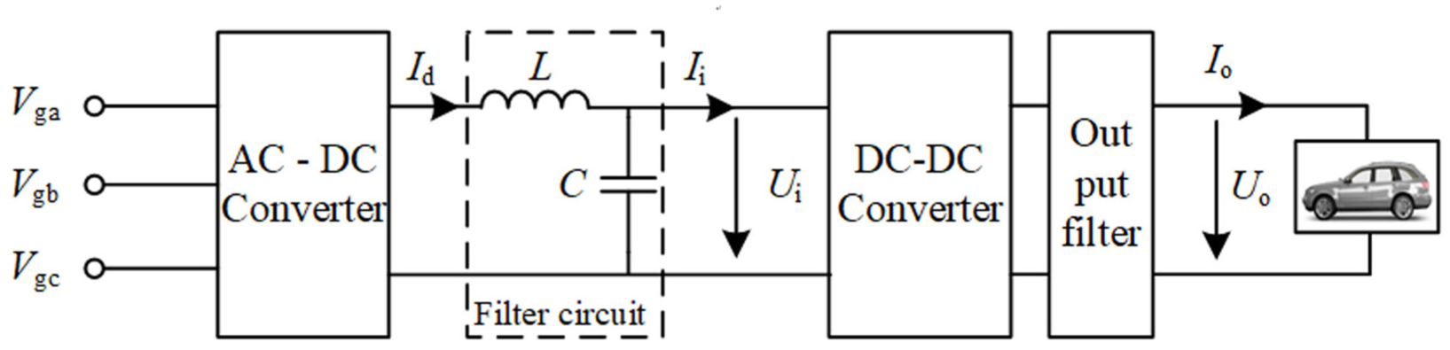
Charging pile structure topology.
EV charging stations can be classified into fast-charging stations and slow-charging stations. Fast chargers (e.g. 120 kW DC fast chargers) can draw hundreds of amperes of current within a short time, causing a sharp increase in line current. According to the formula
Additionally, the startup, shutdown, or transition between charging stages (e.g. constant current to constant voltage mode) can cause abrupt power fluctuations, leading to voltage flicker. Some ultra-fast chargers (e.g. Tesla V3) employ pulse strategies, switching current every 10 s, generating frequency fluctuations in the range of 0.1–10 Hz, which may even induce resonance. In residential areas, slow chargers (e.g. 7 kW) typically use single-phase 220 V connections, which can overload one phase, further exacerbating three-phase imbalance.
Currently, both domestic and international scholars have conducted numerous studies on the impact of electric vehicle charging on power quality. Reference 70 examined the changing characteristics of electric vehicle charging power and harmonic characteristics under different charging modes (fast charging, semi-fast charging, and slow charging). It also analyzed the harmonic characteristics of electric vehicles operating in vehicle-to-grid (V2G) interaction mode based on measured data. Reference 71 considered random influencing factors such as time-of-use electricity pricing, departure time, and waiting time. It modeled the probability distribution of harmonic currents at electric vehicle charging stations and assessed the impact of these stations on distribution networks through probability calculations of harmonic flow. References72,73 used monitoring data from charging stations to quantitatively analyze various power quality issues that arise during the operation of electric vehicle charging stations. Reference 74 employs charging profiles from 12 distinct electric vehicle models—including popular battery electric vehicles and plug-in hybrid electric vehicles—along with high-resolution AC current/voltage waveforms to conduct a power quality analysis. The study evaluates power factor, current and voltage distortion, harmonic content, and load behaviors related to grid voltage and frequency. Reference 75 investigate ways to mitigate power quality issues using renewable energy and distributed generation resources, while at the same time, finding the optimum EV charging speed and strategy to achieve an overall power system-level optimization of the distribution network. Reference 76 presents a novel active compensation-based harmonic reduction (ACHR) technique in order to mitigate the existing third harmonic component in the input current of the power factor corrector (PFC) circuit in electric vehicle (EV) charging systems. Reference 77 innovatively uses a self-tuning filter (STF) and sliding mode control (SMC)-based control algorithm for a grid-interactive off-board electric vehicle (EV) battery charger to power the EV batteries and simultaneously improve the grid power quality.
D-FACTS devices for power quality enhancement
At present, most domestic distribution networks are in the process of upgrading. These networks have initially enabled the friendly integration of high levels of renewable energy, possess some load-side response capabilities, and have started to incorporate artificial intelligence in their operation. 78 However, their ability to support large-scale integration of new energy is still limited. Traditional distribution networks primarily regulate voltage through on-load tap-changing transformers, which adjust the voltage by modifying the transformer ratio without interrupting the load power supply, thus meeting the needs of the power system. However, with the high penetration of distributed energy in the distribution network, frequent voltage fluctuations occur, and there is a delay in the gear adjustment process of on-load tap-changing transformers. These transformers cannot adjust frequently, making them inadequate for voltage regulation in such scenarios.
Series-type regulation equipment
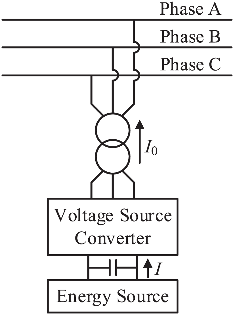
The Distributed Static Synchronous Series Compensator (DSSC) mainly consists of a converter, a series transformer, and a bypass thyristor, as shown in Figure 4. The DSSC derives its DC-side voltage from capacitors or external power sources. By using an inverter, the DSSC injects a controllable series voltage into the line, providing effective damping control and improving the voltage profile under various load conditions, thereby enhancing power system security.
Schematic diagram of DSSC structure.
DSSC configurations can be broadly divided into two types based on the DC-side setup: one utilizing only capacitors and the other incorporating an external DC power source. When capacitors alone are used, the injected voltage is maintained in quadrature with the line current. Consequently, this configuration is limited to reactive power exchange with the system, allowing for adjustment of the voltage magnitude and phase angle. In contrast, the injection of active power necessitates an external DC power source, which increases the implementation cost. The study in
60
explored the application of DSSCs in power markets to alleviate transmission congestion, demonstrating that DSSCs based on PI controllers effectively manage power flow under disturbance conditions. This study primarily analyzes the control strategy of DSSC with an external DC power source, as shown in the control block diagram in Figure 5. The control strategy employs a single-loop voltage control, where
DSSC control block diagram.
Parallel-type regulation equipment
Shunt power flow control devices are connected in parallel to the distribution line, either injecting reactive power into the system through a single-end connection or regulating line power flow via double-end parallel operation. Representative devices include the Distribution Static Synchronous Compensator (D-STATCOM)2–4,64 and the Distribution Static Var Compensator (D-SVC).5,6,63
The instantaneous synchronous compensator D-STATCOM is mainly composed of converters, parallel transformers, bypass thyristors, DC side capacitors and other devices. Its structure is shown in Figure 6. 2 Similar to the DSSC, when the DC side employs capacitors, the voltage injected by the D-STATCOM remains in quadrature with the line current. This characteristic limit its operation to exchanging reactive power with the grid, enabling it to inject or absorb reactive current to regulate voltage at the point of common coupling. Additionally, based on instantaneous power theory, the D-STATCOM can compensate for load imbalance. In contrast to the series-connected DSSC, the shunt-connected D-STATCOM influences the system by injecting current rather than directly adjusting the line voltage amplitude and phase. Consequently, it lacks the capability to control active power flow. It is mostly used to control the reactive power, adjust the effective node voltage, and improve the system power system stability. 3
D-STATCOM structure diagram.
The instantaneous reactive power compensator (D-SVC) is a D-FACTS device that provides voltage support. It consists of thyristor-controlled capacitors and reactors in parallel. 5 The structure is shown in Figure 7. D-SVC uses thyristors to switch capacitors and reactors. By controlling the thyristor firing angles, the D-SVC adjusts the effective reactance, thereby dynamically absorbing or emitting reactive power to the system. Therefore, similar to D-STATCOM, it can be used for system reactive power compensation, voltage support, and adjustable voltage deviation. 6
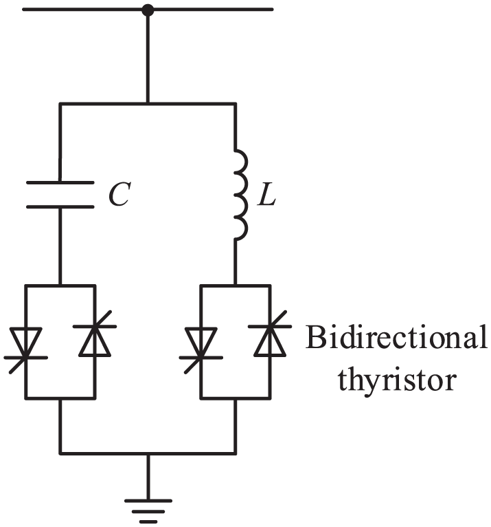
D-SVC structure diagram.
However, both D-STATCOM and D-SVC exhibit response times that are sufficient for mitigating medium-to-low frequency voltage fluctuations but are often too slow to effectively regulate high-frequency disturbances. Their functionality within the network topology is primarily reactive, confined to mitigating node voltage fluctuations caused by generation intermittency or load variations. They lack the capability to proactively address other power quality requirements, such as harmonic suppression. 63
For the control method of parallel regulation equipment, using D-STATCOM as an example, the control objective is to compensate for the reactive power required by the distribution network while maintaining a constant DC side capacitor voltage. 2 The control block diagram of D-STATCOM for achieving these objectives is shown in Figure 8. The control strategy employs a combination of voltage-current dual closed-loop control and d-q axis decoupling control. Gv and Gi are typically proportional-integral (PI) controllers. The voltage outer loop is used to stabilize the DC side capacitor voltage, while the current inner loop controls the grid-connected current of the D-STATCOM. The reference value, iqref, of the q-axis current is determined by the reactive power that needs to be compensated by the D-STATCOM.
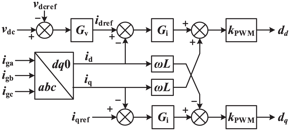
D-STATCOM control block diagram.
The control of D-SVC is relatively straightforward. Its core principle involves adjusting the reactive power output by controlling the thyristor trigger angle in the reactance branch. 5 The control method can adopt either an open-loop calculation approach or a single closed-loop PI control method.
Series-parallel equipment
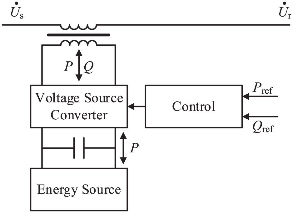
The structure of the Distribution Unified Power Flow Controller (D-UPFC) is illustrated in Figure 9. Structurally, it can be considered a parallel connection of DSSC and D-STATCOM on the DC side. As a result, D-UPFC inherits multiple functionalities from both DSSC and D-STATCOM. On the series side, it can provide continuously variable series voltage within a circular range, enabling selective voltage regulation and phase shifting. This allows for effective grid power flow control, optimized system operation, and advantages in high-renewable-energy scenarios. On the parallel side, D-UPFC can generate or absorb controllable reactive power, regulate voltage at the parallel connection point, support system reactive power compensation, suppress voltage flicker and fluctuations, and enhance voltage distribution when renewable energy is integrated. Additionally, the DC capacitor voltage can be supported by the parallel side, eliminating the need for a separate power supply configuration and thereby reducing costs. 69
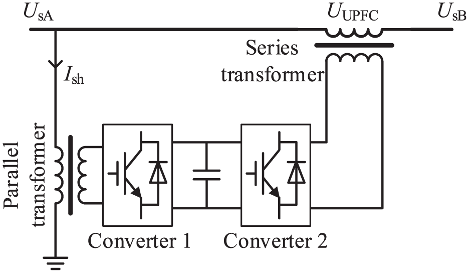
Schematic diagram of D-UPFC structure.
D-UPFC can also mitigate negative and zero-sequence components in the three-phase distribution network using the symmetrical component method, achieving unbalance compensation. Thus, D-UPFC emerges as the most versatile power flow regulation device, capable of addressing multiple distribution network challenges. However, its full reliance on power electronic devices leads to disadvantages such as high costs, significant losses, frequent maintenance, and low reliability.
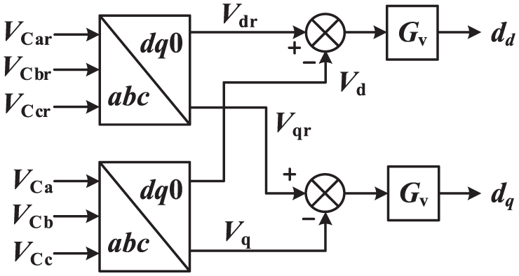
In terms of control, D-UPFC consists of a front-stage rectifier and a rear-stage inverter. The rectifier’s control objective is to maintain DC bus voltage, while the inverter outputs the required voltage vector for grid compensation. 36 The rectifier’s control block diagram follows Figure 10, while the inverter’s control block diagram corresponds to Figure 5. Unlike PST, UPFC allows continuous regulation within the rated power range, providing higher accuracy.
PST structure diagram.
The dual-core symmetrical PST is the most common PST configuration, depicted in Figure 10. 13 Structurally, PST consists of an excitation transformer connected in parallel to the transmission line and a series transformer connected in series with the line. The PST first extracts the line voltage via the parallel excitation transformer, adjusts the voltage amplitude through the regulating winding, and recombines the voltage through winding connections. It then injects the adjusted voltage into the original line via the series transformer, altering the phase angle between voltages on both sides of the line, thereby controlling power flow. 19 The dual-core symmetrical PST in Figure 10 achieves equal voltage amplitudes before and after regulation while only modifying the phase angle, preventing overvoltage generation. However, PST has weak reactive power regulation capabilities, slow response speed, and limited ability to address dynamic problems.
For conventional Phase Shifting Transformers (PSTs), the core principle of the control strategy is to calculate the appropriate gear position based on the phase angle that needs to be compensated. The tap switch is then controlled to connect the corresponding gear position. Since the gear positions of PSTs are discrete, there may be multiple suitable gear positions simultaneously. Taking a dual-core PST as an example, 15 Figure 11 shows the gear selection diagram for phase A. The phase angle to be compensated for phase A is defined as α. From Figure 11, it can be seen that both the second and third gears on the right are suitable, but by comparing the phase angle differences (α1 and α2), it is evident that the third gear is more appropriate.
PST gear selection diagram.
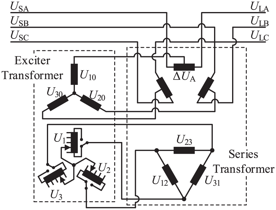
Additionally, the Series Phase Shifting Transformer (SPST) is another structure that has been widely studied. Its design, shown in Figure 12, is an enhancement of the single-core PST, enabling a hexagonal voltage regulation range. It exhibits capabilities similar to the Unified Power Flow Controller (UPFC) and offers significant power control flexibility. 49 While the PST includes a parallel side, it is solely used for obtaining voltage from the line and does not provide reactive power compensation at the parallel point. In contrast to UPFC, the traditional PST employs only transformer components and lacks power electronic devices. Consequently, it outperforms UPFC in terms of cost, losses, and reliability, making it more viable in distribution networks. Reference 15 introduced an innovative type of independent fast phase-shifting transformer (IF-PST), which incorporates two independent regulation windings that can individually adjust the line voltage and active power. This design enhances regulation accuracy and utilizes power electronic on-load tap changers to improve response speed.
SPST structure schematic diagram.
Regarding SPST control, gear selection follows a similar principle to that of PST, though with greater complexity. The control strategy calculates the appropriate gear based on the voltage vector that needs to be adjusted, and the tap switch is used to connect the corresponding gear.
24
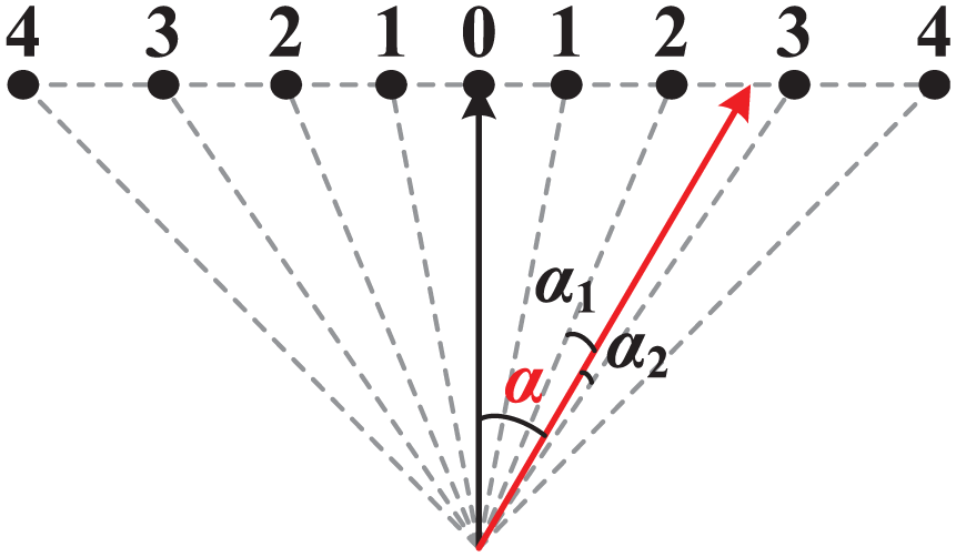
To analyze the gear selection process of SPST for phase A, we use Figure 13, which illustrates the schematic of gear selection for phase A of SPST. First, based on the phase angle and amplitude of the reference voltage vector (
Schematic diagram of phase A gear selection for SPST.
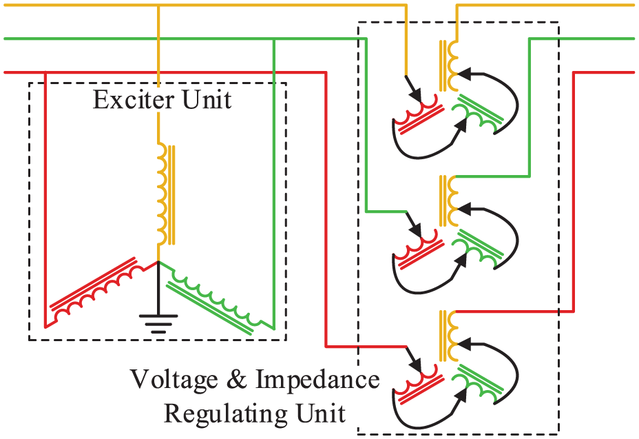
However, PSTs have the disadvantage of discrete control points. Furthermore, due to the high cost of large-capacity power electronic equipment used in UPFCs, some researchers have proposed combining the advantages of both technologies. By using PST for coarse adjustment and small-capacity UPFC for compensation in regions where PST cannot provide coverage, a hybrid approach is achieved. Reference 48 introduced a new hybrid electromagnetic Unified Power Flow Controller (HEUPFC), as shown in Figure 14. This system comprises a large-capacity Sen Transformer and a small-capacity UPFC, providing economic, flexible, high-reliability, and continuously variable amplitude and phase angle outputs. It enables precise control of both active and reactive power flows. Reference 47 proposed an improved hybrid Unified Power Flow Controller (IHUPFC), shown in Figure 15. This design features a simpler structure, a broader phase angle adjustment range, and continuous active power flow control.
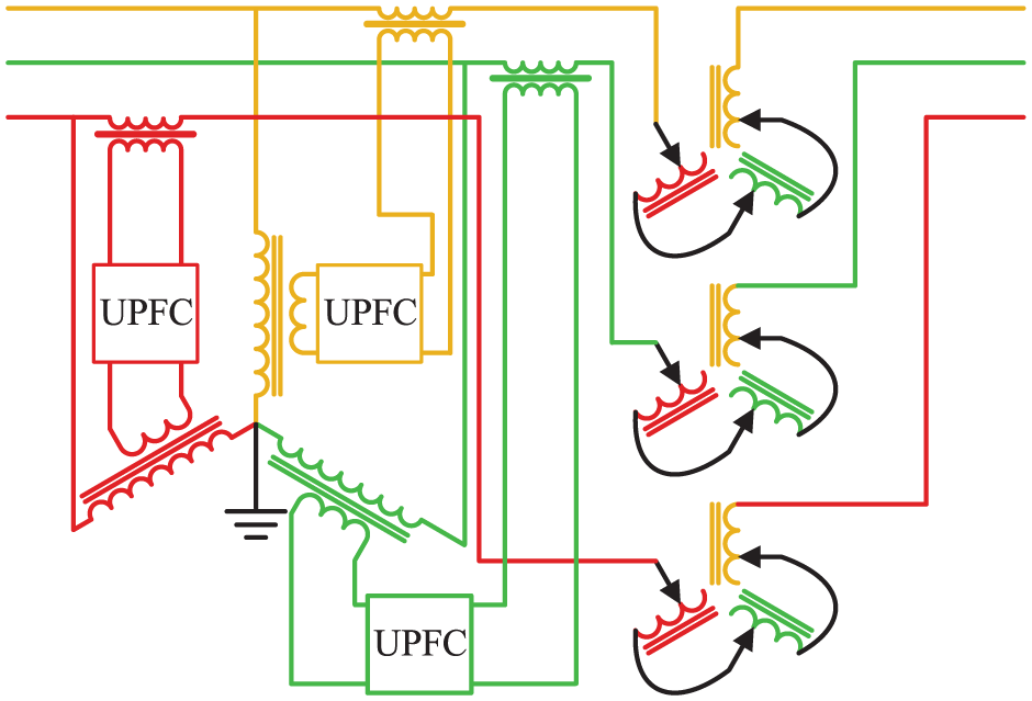
HEUPFC structure diagram.
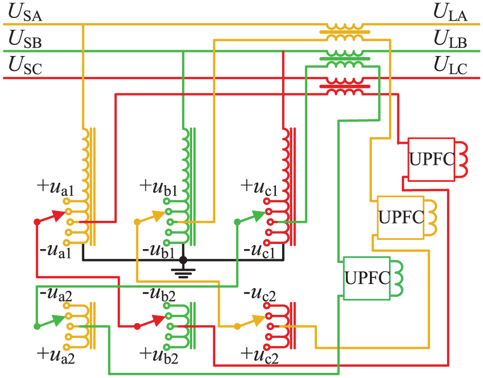
IHUPFC structure diagram.
For hybrid distribution network regulation devices, the current approach combines SPST and UPFC, with SPST handling coarse adjustment and UPFC managing fine adjustment.
48
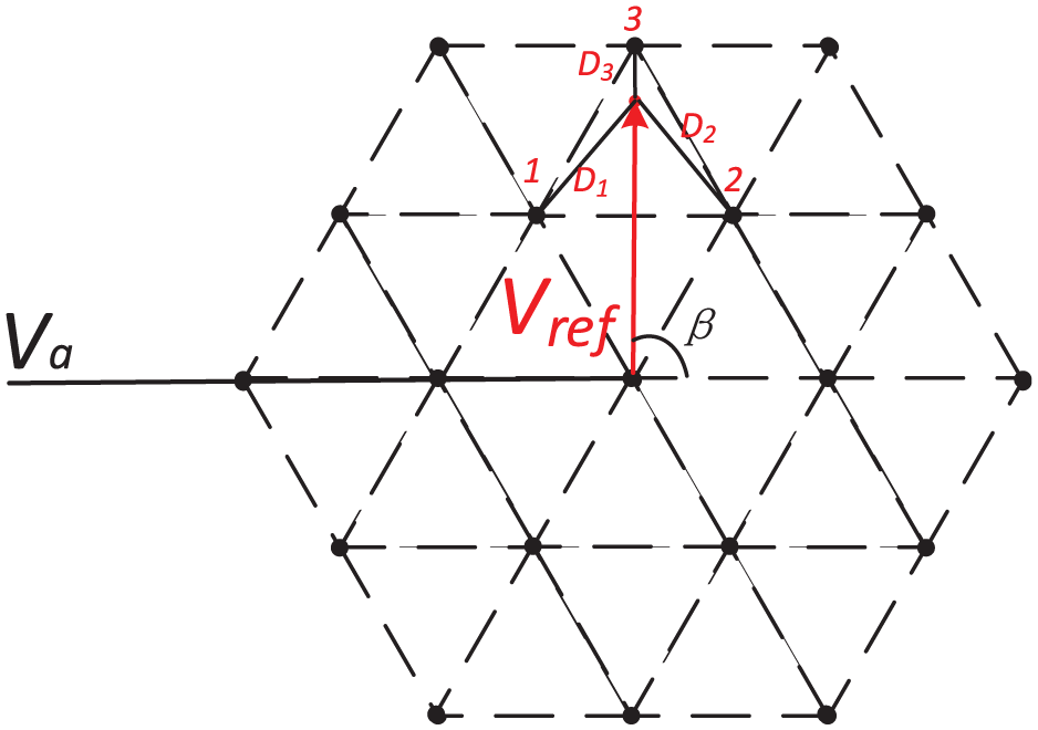
When the excitation winding is connected in a delta configuration, the regulation method for the hybrid distribution network flexible interconnection device is shown in Figure 16. The dots in Figure 16 represent the adjustment gears of the SPST, and the circled portion indicates the adjustment range of the UPFC. Similar to SPST gear adjustment, the point with the closest Euclidean distance to the top of
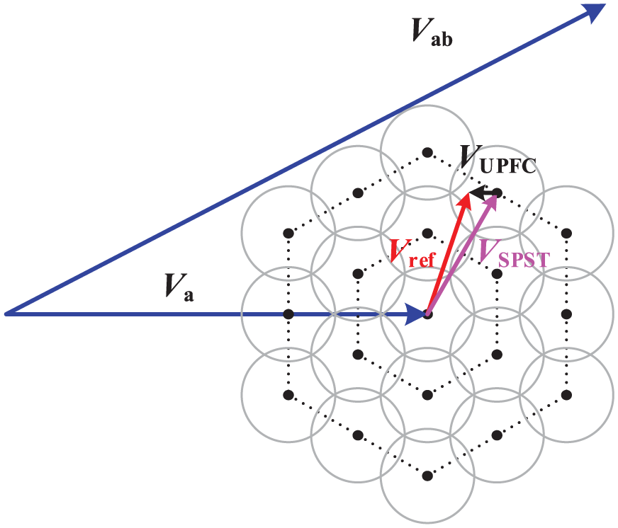
Schematic diagram of control for flexible interconnection device in hybrid distribution network.
Comparative analysis of distribution network devices
Although various power quality management devices are available for distribution networks, their performance and applicability vary considerably. They can be categorized into series, shunt (parallel), and series-shunt types, each with distinct characteristics:
1) Series-type devices are characterized by proven technology, reliable power quality regulation, and high implementation feasibility. They operate by injecting a controllable voltage in series with the line to manage power quality. A primary limitation, however, is that most advanced series devices are based on power electronics, which incurs high costs and significant power losses.2) Shunt-type devices:
The D-SVC is capable of voltage adjustment, reactive power compensation, and can partially mitigate three-phase imbalances. Its drawbacks include complex installation, slow response speed, and limited regulation accuracy.
The D-STATCOM also provides voltage regulation, reactive power compensation, and three-phase imbalance correction. However, its use of complex power electronic commutation techniques results in high cost, substantial losses, and relatively low reliability.
3) Series-shunt-type devices:
Power electronic-based solutions, such as the Distribution Unified Power Flow Controller (D-UPFC), offer the most comprehensive functionality, featuring robust power flow control capabilities and the potential to facilitate network loop closure. Their major disadvantages include a large physical footprint, very high cost, significant losses, and reliability concerns.
Electromagnetic-based Phase-Shifting Transformers (PSTs) also provide strong power flow regulation and can aid in loop closure. They present distinct advantages, including lower cost, higher efficiency, a compact size, and high reliability.
Tables 1 and 2 presents a comprehensive performance comparison and power quality optimization ability of different D-FACTS devices for distribution networks respectively.
Comprehensive performance comparison of D-FACTS devices.
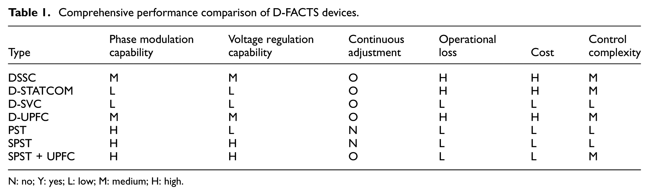
N: no; Y: yes; L: low; M: medium; H: high.
Power quality optimization ability comparison of D-FACTS devices.
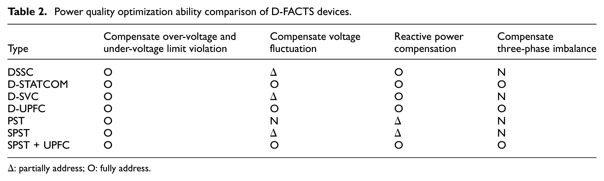
Δ: partially address; O: fully address.
Conclusion
With the large-scale integration of distributed clean energy and the emergence of new loads, such as electric vehicles, the role of the distribution network has evolved from traditional transmission and distribution to a multifunctional platform integrating power generation, transmission, distribution, storage, and trade. This operational shift introduces new power quality challenges, which can be effectively managed by incorporating D-FACTS devices into the distribution network.
Different FACTS devices address various power quality challenges:
(1) Voltage deviation issues: All D-FACTS devices discussed can be utilized.
(2) Voltage fluctuation problems: Suitable devices include D-STATCOM, D-UPFC, and SPST +UPFC.
(3) Reactive power compensation: Options include DSSC, D-SVC, D-STATCOM, D-UPFC, and SPST + UPFC.
(4) Three-phase imbalance correction: Recommended devices include D-STATCOM, D-UPFC, and SPST + UPFC.
This paper reviews current distribution network power flow regulation devices and technologies, comparing their comprehensive performance to provide theoretical insights for distribution network operation, planning, and transformation.
Footnotes
Acknowledgements
The authors disclosed receipt of the following financial support for the research, authorship, and/or publication of this article: This work has been supported by the State Grid Fujian Electric Power Co., Ltd. Technology Pro-ject, Development and Application of Electromagnetic Hybrid Core Equipment for Flexible Networking of Distribution Networks (52130423004N).
Ethical consideration
This study does not involve human participants, animal experiments, or any other research that requires ethical approval. Therefore, no ethical approval was needed.
Consent to participate
This study does not involve human participants, and therefore, no consent to participate was required.
Consent for publication
This study does not involve any potentially identifiable images or data, and therefore, consent for publication was not required.
Author contributions
Conceptualization, Y.F., J.Y. and F.X.; methodology, W.C., X.F. and F.X.; software, J.L. and G.M.; validation, X.H., Z.L. and J.J.; formal analysis, J.L. and Z.L.; investigation, J.J, X.H. and G.M.; resources, X.F. and J.J.; data curation, X.F., J.J. and G.M.; writing—original draft preparation, X.F., J.J. and G.M.; writing—review and editing, W.C., Y.F., D.Z., J.Y. and F.X.; visualization, J.L. and X.H.; supervision, X.H., Z.L. and F.X.; project administration, J.Y. and W.C.; funding acquisition, W.C. and Y.F. All authors have read and agreed to the published version of the manuscript.
Funding
The authors disclosed receipt of the following financial support for the research, authorship, and/or publication of this article: This work has been supported by the State Grid Fujian Electric Power Co., Ltd. Technology Pro-ject, Development and Application of Electromagnetic Hybrid Core Equipment for Flexible Networking of Distribution Networks (52130423004N).
Declaration of conflicting interests
The authors declared no potential conflicts of interest with respect to the research, authorship, and/or publication of this article.
Data availability statement
We encourage all authors of articles published in Measurement and control journals to share their research data. In this section, please provide details regarding where data supporting reported results can be found, including links to publicly archived datasets analyzed or generated during the study. Where no new data were created, or where data is unavailable due to privacy or ethical restrictions, a statement is still required.