
Abstract
In the process of dynamic motion of biped robot, the irregular ground touch will occur under the influence of the external environment, and the control efficiency of the unstable support configuration will directly affect the motion stability. The randomization method to set the landing impedance of the swinging leg of the biped robot will cause the overall walking posture to become unstable, resulting in the impact of the foot force of the biped robot. Therefore, an improved impedance control technique for swinging leg landing of biped robot based on switching tree is designed in this paper. The linear relationship between the foot force and the leg length of the swinging leg was analyzed by the five-link model, and the leg stiffness of the swinging leg was determined. The trajectory of the biped robot is adjusted by the feedback force, and a spring physical model is assumed in the position impedance control. Considering the coherence and coordination of the biped robot in the walking process, the switching tree algorithm finds the minimum switching tree and the maximum switching tree of the landing impedance of the biped robot swinging legs, and precisely sets the impedance by determining the optimal node, so that the force of the foot in contact with the ground can change smoothly according to the expected way. newTree is obtained from oldTree from the swinging leg landing motion of the biped robot until no exchangeable tree exists, and the control improvement of the swinging leg landing impedance of the biped robot is completed. The experimental results show that after the impedance control is added to the method, the landing tracking force value of the swinging leg of the biped robot is 5 N, the trajectory tracking accuracy is the highest 99%, the joint Angle deviation is maintained between 0.15° and 0.24°, and the control response time is between 2.35 and 3.02 ms, which can improve the landing stability of the swinging leg of the biped robot.
Introduction
Footed robots take footed animals as bionic objects, have good flexibility and stability. 1 During the walking process of bipedal robot, it is unavoidable to interact with the environment, especially in the complex terrain, the unpredictable contact with obstacles, different degree of softness of the ground, and the impact of the swinging leg on the ground, etc., which can easily cause the robot’s position to be unstable. 2 For stable operation, the robot needs to implement impedance control to enhance environmental adaptability. Secondly, when the robot carries out non-routine movements such as falling from height, the impact of the landing process will cause great damage to the robot’s mechanical structure and drive device, 3 control leg flexibility, reduce landing impact, and promote smooth landing. Impedance control is a commonly used leg flexibility control strategy, which integrates force control and position control into one framework, and has better robustness and less task planning workload. 4 Currently, conventional impedance control takes the second-order mass-damped-spring (or damped-spring system) as the target impedance model, and equates the system into a mass-damped-spring system, which leads to certain defects in the improved impedance control technique for bipedal robots with swinging legs due to the existence of the contact stability and the contact transition performance. For this reason, researchers in this field have designed more methods.
Huang et al. 5 presented a sensorless impedance controller for a robot manipulator that does not use a force estimator. Optimize target impedance, match robot configuration, eliminate force feedback term, and achieve sensorless impedance control. The new design has similar performance to traditional control and acceptable force changes. Develop an adaptive version for uncertainty, which performs well without the need for force sensing. In sensorless impedance control, if the impedance parameters are improperly adjusted, the robot cannot maintain a stable posture while walking, making the robot too sensitive to the response of external forces, resulting in violent or shock. Li et al. 6 proposed the optimization of grinding quality through force control, proposed the position force tracking adaptive impedance strategy, considered the environmental interaction, introduced Lyapunov adaptive adjustment trajectory, and used six-dimensional force sensing to accurately measure the contact force, thus improving the grinding accuracy of aviation complex surfaces. Although the Lyapunov adaptive adjustment trajectory is introduced to improve the adaptive ability of the system, the algorithm can not react quickly in the face of sudden situations in practical application, resulting in impact phenomenon. Rhee et al. 7 hybrid impedance conductance control optimizes robot operation and complements to enhance performance. Good resistance control in the rigid ring and excellent conductivity in the soft ring. The new strategy switches based on switch conditions, integrating the advantages of both. In mixed impedance admittance control, if the switching condition is not properly set, the control strategy will switch frequently between rigid control and flexible control, or the switching time is not appropriate, which will affect the stability and walking posture of the robot. Khan et al. 8 adopted the principal component analysis method and used the maximum variance to capture the running state of the robot linearly. In the potential dimension, the variance value was allocated according to the nonlinear autoencoder to realize the research on the continuous gesture control of the robot arm. If the robot is carrying out walking and arm gesture control at the same time, and there is no good coordination or synchronization between the two control strategies, the arm movement will interfere with the stability of walking and lead to the instability of walking posture. Yang et al. 9 proposed a robot visual control method based on adaptive fault tolerance. A decoupling method is introduced to construct an actuator fault uncertainty parameter model, which is separated from the dynamic model. According to Lyapunov analysis method, the robot operation control is realized, and the effectiveness of the proposed control scheme is verified. In practical applications, if the system model is too complex or there are unmodeled dynamic characteristics, then the Lyapunov analysis method cannot describe the behavior of the system completely and accurately, resulting in poor effect of the control strategy in practical applications, thus affecting the walking posture and foot force of the robot.
In the study of the above methods, this paper designs a new impedance control technology for the swinging leg landing of biped robot based on switching tree. The key research routes of this method are as follows:
(1) An in-depth analysis of the landing motion of the swinging leg of a biped robot is carried out through the five-link model, and it is found that there is an approximate linear relationship between the sole force and the leg length, which provides a new theoretical basis for determining the leg stiffness value of the swinging leg.
(2) The combination of feedback force adjustment and position impedance control enhances the robot’s adaptability to complex environments and enables the robot to cope with various challenges more smoothly during walking.
(3) The switching tree algorithm is introduced to solve the problems of coherence and coordination in the walking process of biped robots. By finding the minimum switching tree and the maximum switching tree of the landing impedance of the swinging leg, and determining the optimal node to set the impedance accurately, the research realizes the smooth control of the force when the foot contact with the ground. This method not only improves the walking stability of the robot, but also significantly optimizes its walking efficiency.
Improved impedance control technique for bipedal robot swing leg landing based on switching tree
Analysis of bipedal robot swing leg landing motion
The bipedal robot focuses on fast movement and running, controls the landing speed and position of the swinging legs, controls joint forces with impedance, and buffers the landing. Static walking, control the support legs to squat, reduce the swinging legs to lower the ground speed, avoid ground collisions, and walk steadily. However, the static walking cycle is long and cannot be effectively utilized in practice. Therefore, subsequent research will incorporate inertial forces to plan dynamic walking of robots, including fast walking and running gaits.
In bipedal robot walking, if only the kinematics problem in the forward direction is considered, the model of the robot can be simplified to a five-link model, 10 which is shown in Figure 1 as follows.
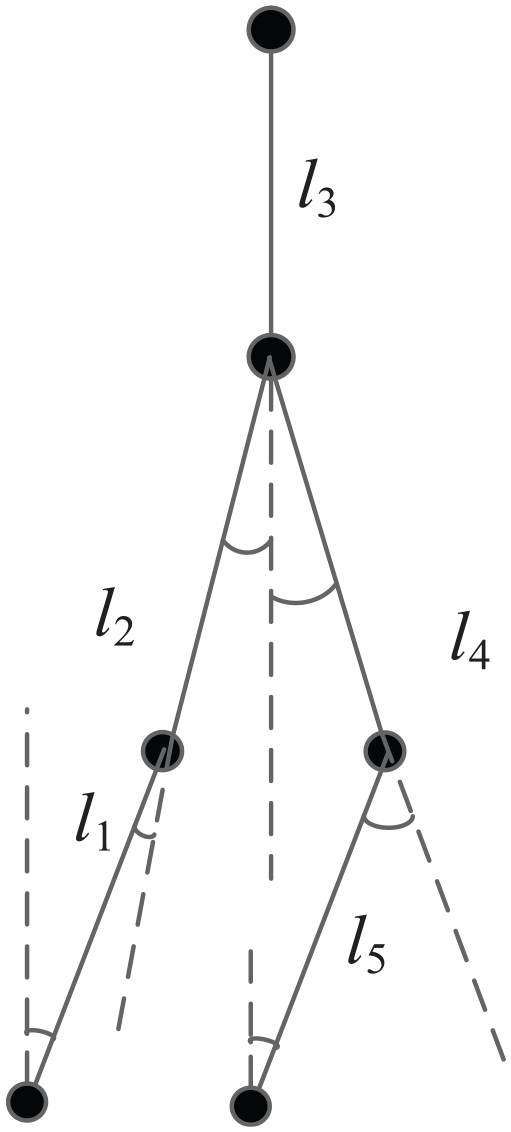
Schematic diagram of the angular model of the bipedal robot’s swing leg landing motion.
In Figure 1,
In the motion analysis of the swinging leg landing of a biped robot, the transformation relationship between the two connecting rods is obtained to accurately determine the position of the end of the swinging leg (foot). The leg of a biped robot can be regarded as a kinematic chain composed of multiple links. For the swinging leg, the transformation relationship between the two links can be gradually calculated from the position and attitude of the root joint (such as the hip joint) to the end joint (such as the ankle joint). When swinging the leg from the swing state to the landing process, we need to know the exact position of the foot relative to the hip joint in order to plan the appropriate landing trajectory, avoid collision and ensure a stable landing posture. It is known that the transformation relationship between the two connecting rods is:
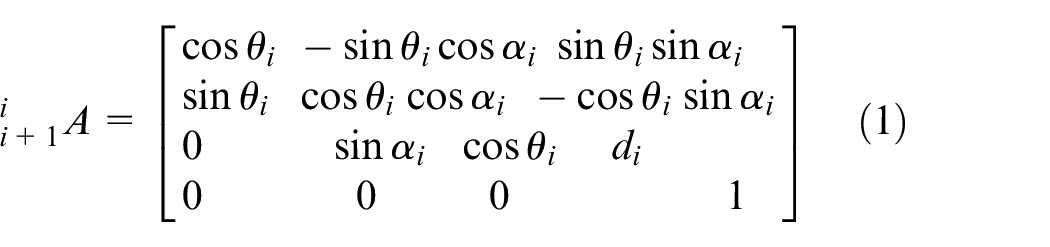
In the formula,
The motion of the bipedal robot is modeled as:

In the formula,
Among them,
Leg stiffness determines many kinematic characteristics of a robotic system, such as gait period and total system energy. Researchers usually use mathematical modeling to obtain leg stiffness values. 12 When the biped robot swings its legs, it will be affected by the impact force of the ground, and the stiffness of the legs can play a role in cushioning and absorbing energy. When the robot lands from a certain height of the swing state, the legs with appropriate stiffness can, like a spring, convert the kinetic energy of the moment of landing into elastic potential energy, thereby reducing the impact on the robot structure and control system. If the stiffness of the legs is too large, the impact force can not be effectively buffered, resulting in excessive force on the joints and structure of the robot, and even damage; If the legs are just too small, the robot will sag too much and it will be difficult to maintain balance. Leg stiffness: The definition of stiffness at the distance from the center of gravity to the foot end.
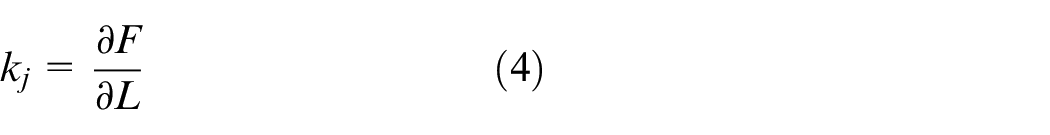
In the formula,
Assuming an approximately linear relationship between plantar force and leg length, the leg stiffness can be expressed as follows:
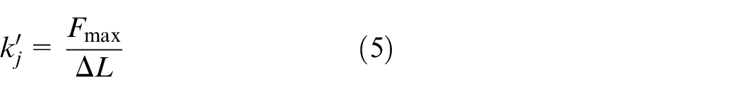
Among them,
Based on the analysis of the SLIP model, it is believed that the change in leg length 13 is equal to:

The horizontal velocity of the center of mass during landing is constant the

By comparing the measured values with the values calculated by the model, the maximum value of plantar force was calculated to be equal to:

In the formula,
The leg stiffness value is obtained through the above calculation, and the kinematic analysis of the biped robot swinging leg landing is realized.
Analysis of bipedal robot swing leg landing impedance control principle
Position controlled impedance adjustment robot foot force/displacement Feedback foot force to the controller, adjust trajectory error, inverse kinematics calculate motor angle, and real-time control foot force and position. 14
Position control structure: outer loop impedance controls motor angle, inner loop adjusts position. The control method begins with the contact force of the outer ring, and according to the impedance relationship

Where,
Subsequent research will be based on equations and combined with control algorithms to determine the required force control performance, let the difference between
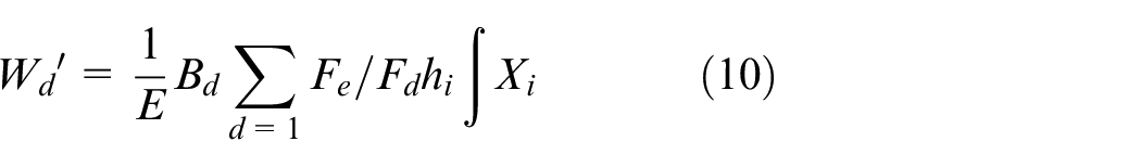
A Lattice transformation of equation (10) yields the impedance control equation modeled in the frequency domain 17 as shown in equation (11), namely:
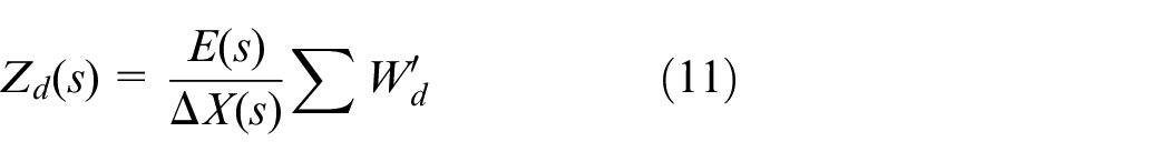
Based on the analysis, the impedance control framework in Figure 2 is obtained. In practice, because the desired displacement of the control method is determined by the height of the ground, the specific location of the environment can not be predicted and can only be estimated. At the same time, the environment in contact with the outside world is not constant when the robot is moving, so it is basically impossible to satisfy the conditions in the formula. 18 Under high collision stiffness, small errors have a significant impact on impedance control, making traditional impedance difficult to accurately control. Therefore, adaptive impedance control has been developed.
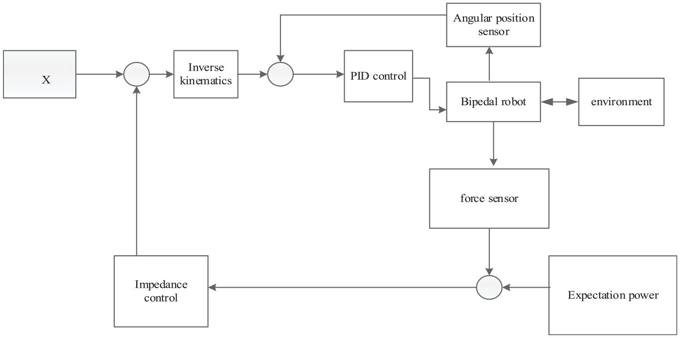
Impedance control fundamentals.
In Figure 2 in the bipedal robot system, inverse kinematics is used to solve the joint variables according to the desired foot position and attitude, and the Angle position sensor provides the actual Angle information of the joint to assist the motion control. The force sensor measures the interaction force between the robot and the environment, and the expected force is the pre-set target force value. The environment affects the robot’s movement and stress situation, PID control precisely adjusts the joint Angle and other physical quantities, and impedance control regulates the interaction force between the robot and the environment.
Improved impedance control technique for swing leg landing of bipedal robot based on switching tree
To improve the impedance control performance of bipedal leg swinging landing, this paper uses the switching tree algorithm to improve the impedance control technology.
The commutative tree is an acyclic connected graph, consisting of a vertex set (binary tree root node partial order) and an edge set. The minimum partial order of the leaf set, and the parent also belongs to the point set, numbered 0, 1, 2. 19 If two nodes in the tree have the same father, then these two nodes are called brother nodes. The improved impedance control technique for bipedal robot swing leg landing is realized by the minimum common ancestor of the algorithm and a common minimum upper bound for each node under the partial order relation etc. The program of the algorithm is shown in Table 1:
Algorithm program.
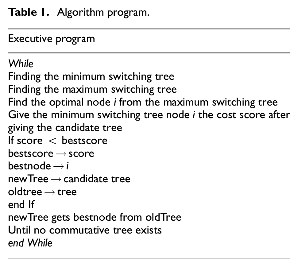
Improved impedance control technique for bipedal robot swing leg landing based on switching tree algorithm. 20 When walking at high speeds, the impact force of swinging legs on the ground significantly affects walking stability. No active soft equipment, control the joint force of swing legs to reduce landing impact, simulate spring buffering. 21 The energy of robot leg swinging includes body kinetic energy and center of mass movement kinetic energy. When there is a buffering device, the total kinetic energy is converted into elastic potential energy, which is absorbed at zero end velocity and lands steadily. Without buffering, control joint force, record the change in center of mass after impact, adjust the relationship between function and total energy, and modify the technology in three stages. 19
(1) First stage. Find the minimum and maximum switching trees for the impedance of bipedal leg swinging to ground, and determine the optimal impedance node.
Before swinging both legs and touching the ground, use their terminal velocity. In this stage, the robot does not have contact with the external environment, so it is just purely based on the velocity change of its end position in the vertical direction to control the robot’s joint force, so that the control effect can be achieved in the instant when the robot falls to the ground to avoid transient hard collision, which indirectly plays a pre-control role of the landing control, 22 and the flow of the control algorithm of this process is shown in Figure 3.
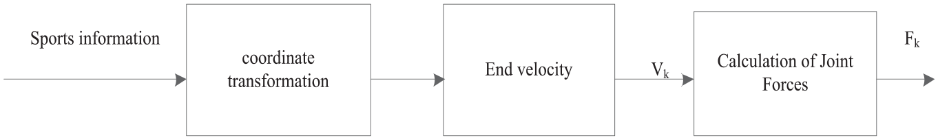
Velocity variation at the end position of the swing leg of a bipedal robot.
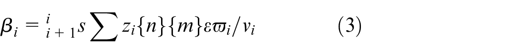
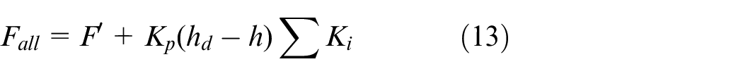
In terms of altitude control, two altitude control methods are carried out in this paper. One method is to control the height at the highest point of the center of mass, and add radial thrust to the rear half of the landing leg. To compensate for the energy loss of the robot and enable the robot to reach the target height of Xiao et al. 23 The second method is to control the height with the highest point of both hips, and apply thrust to the back half of the leg to supplement energy and achieve the target height. 24 The active thrust is calculated as follows:
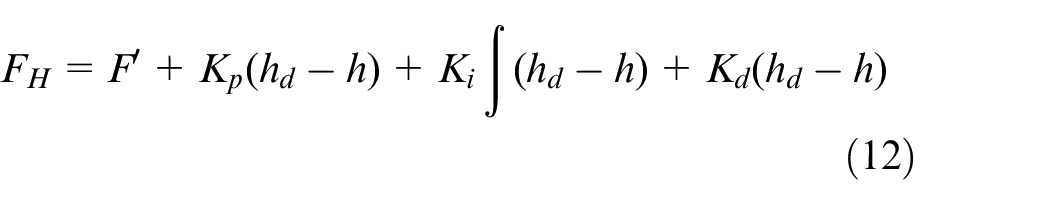
In the formula,
(2) Phase 2: Determine the minimum switching tree node for swing legs and generate values for candidate trees.
The final speed of swinging the leg to the ground is zero, no more input is made. Control ankle and knee strength, with non-zero vertical velocity of the center of mass. Use center of mass deceleration to control the landing platform. 25 Given the swing height, the total energy of the bipedal machine when hitting the ground is:
In the equation,
Speed control: Landing point planning speed regulation, horizontal force compensation deviation, precise speed following. Specifically, during flight, the main leg plans the landing angle and the auxiliary leg follows suit. When landing, add water leveling force to the main leg. The planning perspective and computational power are as follows.

In the formula,
The difference between the bipedal robot plane model and the single-legged subsystem control is that the pitch angle needs to be adjusted so that the robot legs have enough leg room. Control strategy: Increase the maximum positive and negative pitch angle of the jumping cycle, and maximize the pitch angle when switching back and forth when the front leg lands on the groundSimilarly, the pitch angle is minimized when switching back and forth while landing on the hind leg. Calculate the average pitch angle and aim for near 0° to ensure self stabilization. The deviation between the average pitch angle of the fuselage and the target value of 0° is used for PID calculation as the sole of the foot. The compensation force adjusts the fuselage pitch angle by applying plantar force compensation along the front and rear leg directions. The formula for calculating the plantar force compensation value is:
In the formula,
To verify the correctness of variable stiffness control during high-speed jumping, this article uses a variable stiffness impedance controlled bipedal machine, equivalent to a virtual impedance spring leg. Based on the SLIP model, but the mass is not single leg and needs to be increased. The mass of the previous part of the fuselage, but the specific mass cannot be calculated using mathematical formulas. It is necessary to experimentally measure the center of mass mass of the SLIP model of the front and rear legs. The actual leg length of the robot is 1 to the impedance controller which generates radial spring forces according to
In the formula,
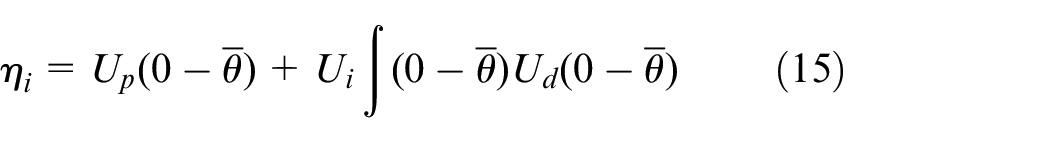
(3) The third stage. From the swing leg landing motion of the bipedal robot, newTree is obtained from oldTree until there is no exchangeable tree. In the final stage, the energy constraints of the bipedal robot are controlled. During the entire process of swinging leg landing control, each control quantity output must satisfy that the energy generated by its work is always less than the energy generated during the swinging leg landing movement of the robot, that is:
In the formula,
If the energy of the landing system is stable, then the body is stable and the control is achieved. The algorithm is shown in Figure 4.
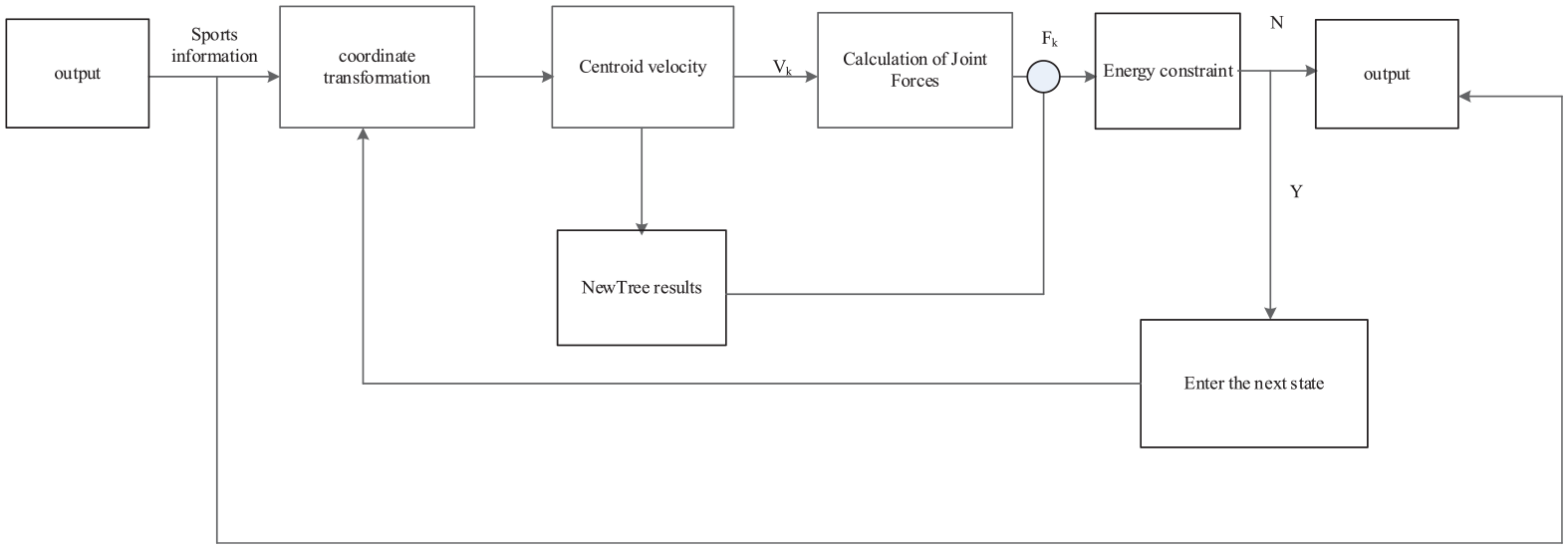
Improved impedance control flow for bipedal robot swing leg landing.
Experimental analysis
Experimental parameter design
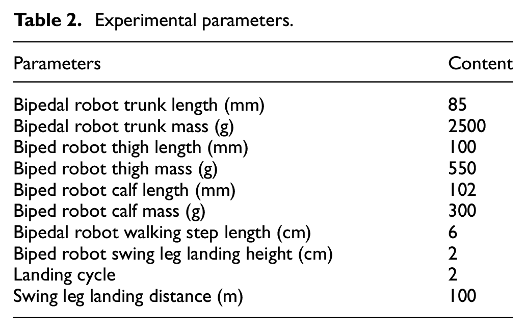
The validation method is effective, and pre planned gait experiments are used for analysis, the impedance of the bipedal robot’s swinging leg to land was controlled, and the experiments were carried out before the experiments, and after the control was added, respectively, in the walking mode. Given the parameters of the connecting rod, the experimental parameters are designed as shown in Table 2.
Experimental parameters.
The physical drawing of the experimental bipedal robot is shown in Figure 5.
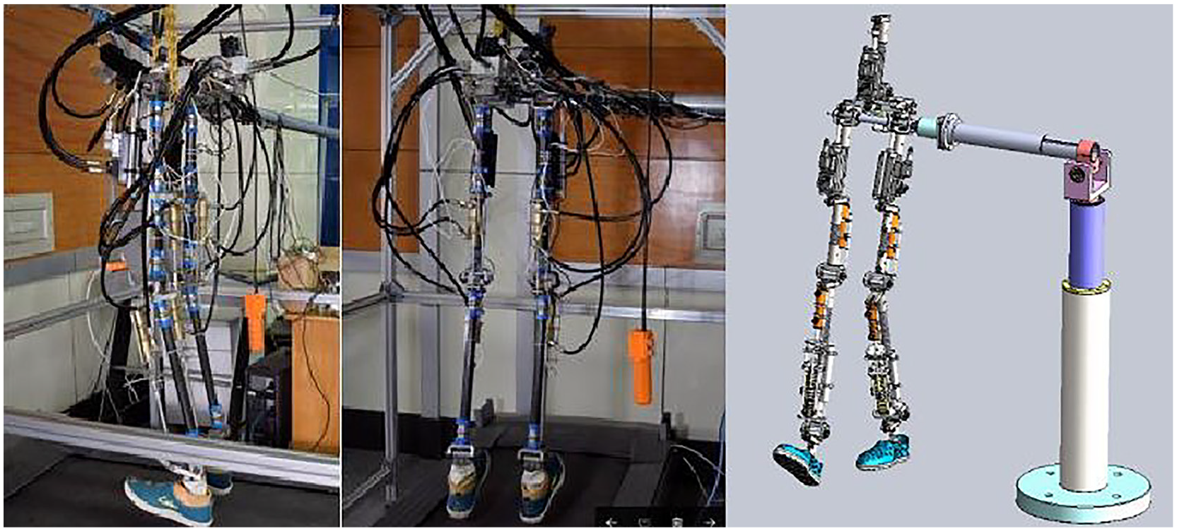
Schematic diagram of the experimental bipedal robot.
Analysis of experimental results
Stable energy leads to stable body and control, as shown in Figure 4.
Figure 6 shows the difference in contact force between impedance controlled (dashed line) and uncontrolled (black solid line), with an expected force of 5 N (thin dashed line) as a reference. The foot end force without adding impedance control will not only have a secondary impact, but also stabilize at a position greater than the expected force. After adding impedance control, although there will still be an impact on the feet of the bipedal robot when the swing leg lands, it will respond quickly and adjust to a value close to the desired force, and slowly reach a stable tracking force value of 5 N. Impedance control precision and external contact force, feedback system increases flexibility, achieving impedance effect.
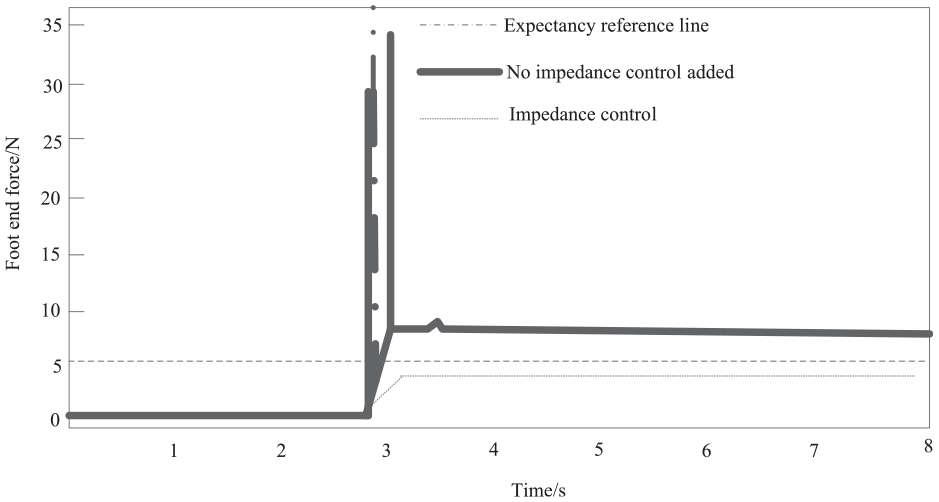
Tracking curves of the swing leg landing foot end of a biped robot with and without impedance control.
To verify the feasibility of the method, this article and Huang et al. 5 and Li et al. 6 were used to analyze the improved impedance control stability of bipedal leg landing, as shown in Figure 7.
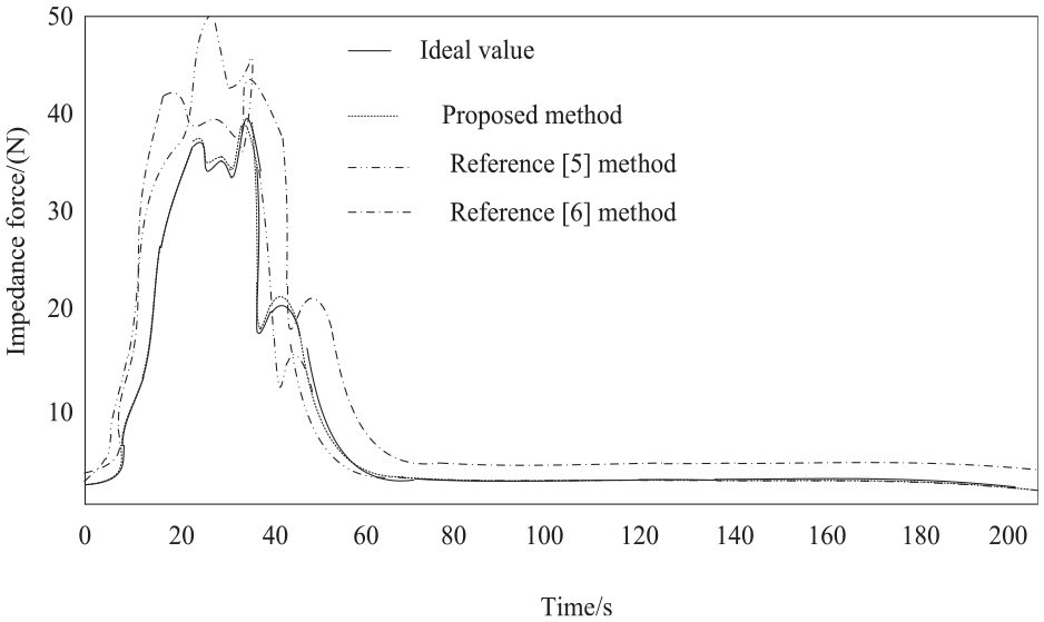
Improved impedance control stability of bipedal robot swing leg landing.
Figure 7 shows that as the swinging leg lands, impedance increases and stability improves. This grammar is closer to the ideal curve, while the methods in Huang et al. 5 and Li et al. 6 improve stability by a greater distance from the ideal value, which is less feasible than this grammar. This is because the proposed method relies on the feedback force to adjust the trajectory of the biped robot and adopts the spring physical model in position impedance control. The function of the feedback force is to monitor the motion state of the robot in real time and correct the trajectory according to the actual situation. The spring physical model can simulate the interaction between the robot and the environment in the position impedance control, so that the robot can make a reasonable response in the face of external interference. When the robot is walking on uneven ground, the spring physical model can adjust the movement of the robot’s legs according to the fluctuation of the ground surface to maintain the overall stability.
Three experimental evaluations were conducted on the landing accuracy of bipedal robots with swinging legs: the new method, Huang et al. 5 and Li et al. 6 The results are shown in Table 3.
Bipedal robot swing leg landing trajectory tracking accuracy (%).
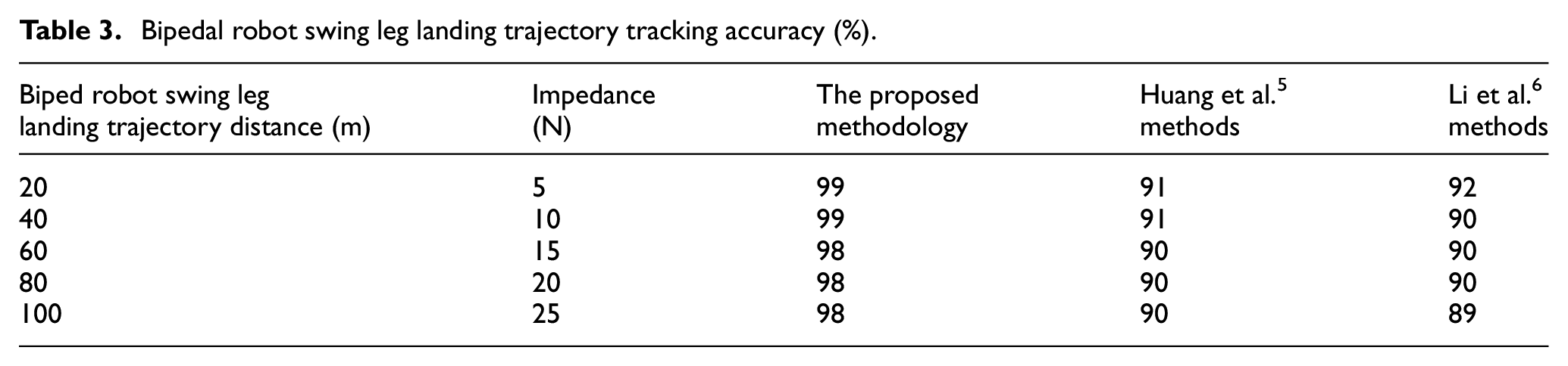
Table 3 shows that the new method has the highest tracking accuracy (98%–99%) with respect to the landing trajectory and impedance changes of the swinging leg, which is superior to Huang et al. 5 (91%) and Li et al. 6 (92%), demonstrating better performance. The main reason is that the proposed method uses the five-link model to analyze the approximate linear relationship between the sole force and the leg length of the swinging leg of the biped robot to determine the leg stiffness value. When the stiffness value of the leg is determined, the leg can better adapt to the ground reaction force and maintain the expected movement trajectory according to the relationship between the sole force and its own length during the swinging leg landing. In the whole movement process of the biped robot, the accurate leg stiffness value enables the swinging leg to move more accurately according to the pre-planned trajectory when landing. The reason for the slight error is that although the spring physical model can simulate the interaction between the robot and the environment well in theory, there may be some differences between the spring physical model and the real physical interaction in practical application due to the idealized assumptions of the spring model, which will have a certain impact on the trajectory tracking accuracy.
In order to verify the stability and control performance of an improved impedance control method for swinging leg landing of biped robot based on switching tree technology, joint Angle deviation and control response time were selected as evaluation indexes. Among them, the movement of each joint of the biped robot directly affects the overall posture of the robot. For example, changes in the Angle of the hip, knee and ankle joints determine leg extension and bending, as well as the robot’s standing and walking posture. If the Angle deviation of the joint is too large, it means that the joint does not move according to the expected movement mode, which will cause the body action of the robot to deviate from the normal state, and then affect the stability of the overall posture. In practical applications, biped robots will encounter various external disturbances, such as sudden external force impact and terrain changes. The control response time measures the speed from when an external disturbance occurs to when the robot responds effectively. The results obtained are shown in Table 4:
Comparison of joint angle deviation and control response time results of different methods.
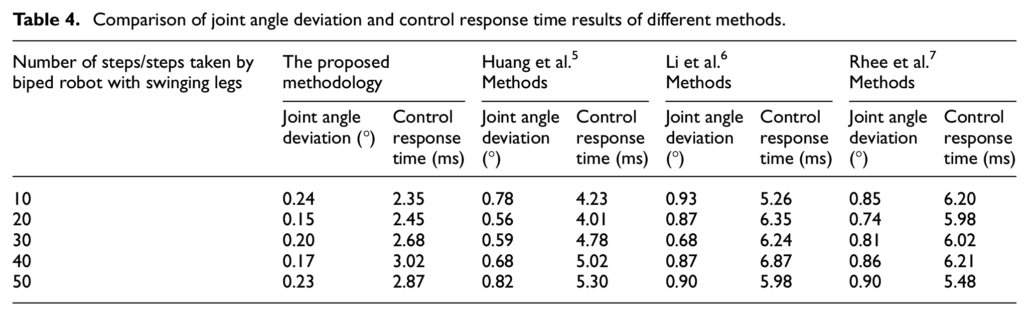
Analysis of the test results in Table 4 shows that, under all walking steps, the joint angle deviation of the proposed method is maintained between 0.15° and 0.24°, and the control response time is between 2.35 and 3.02 ms. The overall response speed is relatively fast, and there is little change under different steps, indicating that the method can respond quickly to external interference. It has significant advantages in stability and control performance. Because the switching tree algorithm cited in the proposed method takes into account the coherence and coordination of the biped robot walking, and finds the minimum switching tree and maximum switching tree of the landing impedance of the swinging leg, when the impedance is precisely set, the force of the foot in contact with the ground changes smoothly in the expected way. This smooth force change helps to maintain the overall stability of the robot, thus limiting the deviation of the joint angle. Due to the characteristics of the switching tree algorithm, the appropriate impedance setting can be quickly determined according to the current walking state during the walking of the biped robot, and then the response time of the whole control process can be affected.
This method can not only effectively reduce the joint Angle deviation, improve the posture stability of the robot, but also respond quickly to external interference, and improve the adaptability and robustness of the robot in complex environments. Therefore, the proposed method has high application value and popularization potential in the field of biped robot control.
Conclusion
This article proposes to improve the the impedance control for the landing of the bipedal robot’s swinging leg based on switching tree technology. Through the five-link model to analyze the bipedal robot swing leg landing movement in the fast walking gait and running gait, analyze the approximate linear relationship between the plantar force and the leg length, determine the swing leg leg leg stiffness value, through the adjustment of the robot trajectory, so that the motor torque output, and through the position of the impedance control in the assumption of a physical model of the spring, analyze the principle of the bipedal robot swing leg landing impedance control to determine the improvement of the bipedal robot swing leg landing; analyze the basic flow of the switching tree algorithm, and introduce it to the bipedal robot swing leg landing improvement impedance control technology. Set up three phases according to the algorithm to complete the improvement of bipedal robot swinging leg landing impedance control. The proposed method is consistent with the trend of the ideal curve in terms of the stability of the improved impedance control of the swinging leg landing of the biped robot. Compared with the Huang et al. 5 method, the tracking accuracy of the swinging leg landing trajectory is up to 8% higher than that of the Li et al. 6 method, and the tracking accuracy is up to 7% higher than that of the Li et al. 6 method. The joint Angle deviation is maintained between 0.15° and 0.24°, and the control response time is between 2.35 and 3.02 ms, which reflects the rapid response ability of the method in dealing with external interference.
Due to the damping phenomenon of spring physical model in practical application, it will consume the energy of robot movement, and the difference between it and the real physical interaction will affect the trajectory tracking accuracy. In the follow-up study, the spring physical model will be further optimized to reduce idealized assumptions and make it more close to the real interaction between the robot and the environment. When the damping term is added to the spring physical model and the linear damping model is adopted, the damping force will be larger when the robot moves faster, so as to more truly reflect the energy loss during the robot movement, which helps to improve the trajectory tracking accuracy, reduce the idealized hypothesis, and make it more close to the real interaction between the robot and the environment. At the same time, in order to improve the robustness of the entire control system, a more in-depth robustness analysis of the entire control system will be carried out in the future. Robust control theory (such as H∞ control theory) is used to optimize PID controller. The optimal range of PID parameters is determined by solving the H∞ optimization problem, so that the stability and performance of the system can be guaranteed under the condition of uncertainty.
Footnotes
Declaration of conflicting interests
The author(s) declared no potential conflicts of interest with respect to the research, authorship, and/or publication of this article.
Funding
The author(s) disclosed receipt of the following financial support for the research, authorship, and/or publication of this article: Topic (source, name, number) Source: Jilin Provincial Department of Education, Name: Research on the social service function of the on-campus training base of Jilin Provincial Higher Vocational College, Number: JJKH20170360SK
Data availability statement
The datasets used or analyzed during the current study available from the corresponding author on reasonable request.