
Abstract
This scholarly paper offers a wind power generation system (WPGS) that utilizes a configuration of parallel five-phase permanent magnet synchronous generators (PMSGs). The control mechanism for this system is based on a fifteen-switch rectifier (FSR) topology, which is specifically designed for grid-connected applications. To enhance the control performance of the proposed wind system, an Adaptive Neuro-Fuzzy Inference System (ANFIS)-based Backstepping control (BSC) methodology is utilized for both the generators-side and grid-side converters. The suggested control strategy’s effectiveness is assessed by conducting simulations at varying wind velocities and comparing it to a BSC-based control system. The simulation findings demonstrate that the suggested control system consistently ensures precise tracking of the controlled variables. Furthermore, several aspects of the system’s performance show significant improvements. Specifically, the control method successfully reduces power ripples by 30.5%, DC bus voltage overshoot by 3%, and speed overshoot by 100%. Moreover, the proposed technique reduces the overall harmonic distortion of the network current by 44.44% compared to the BSC method. Additionally, the system’s efficiency is enhanced to 96.5%, surpassing the 96% achieved by the BSC method. Compared to good nonlinear control methods, the results indicate that the suggested strategy outperforms.
Keywords
Introduction
Antecedents
The Ukrainian-Russian crisis served as a significant turning point that propelled the transition toward clean and renewable energy, primarily due to the subsequent rise in oil and gas prices. European nations, being major importers of Russian gas, faced significant challenges in coping with the crisis. Despite their previous focus on alternative energy sources, they struggled to mitigate the impact of the crisis. However, the crisis has accelerated the expansion and development of renewable energy, with notable investments being made by China, the United States, and India. The European Union’s REPowerEU initiative sets forth the objective of eliminating dependence on Russian fossil fuels by the year 2027 (Figure 1). The International Energy Agency anticipates that the growth of renewable energy will surpass expectations, resulting in an estimated increase of approximately 2400 GW. 1
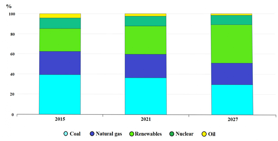
Worldwide power production by different technologies in 2015, 2021, and 2027.
Wind energy is one of the world’s most significant, frequently utilized, and continuously developing forms of energy at the current time. This is because wind energy is an entirely clean kind of energy that does not have any adverse impacts on the environment, including the atmosphere, water, or soil. In addition to the fact that it does not produce any waste or greenhouse gases (Figure 2), it has also seen a reduction in price in comparison to the years before as a result of the significant advancements that have been made in the area of renewable energy.2,3
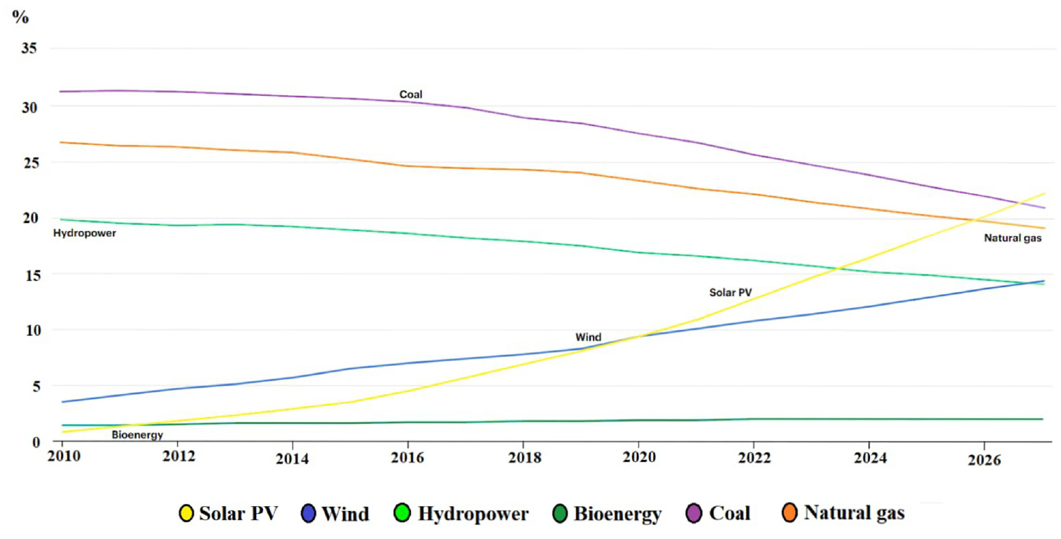
Division of total produced electricity capacity by the generating technology.
One of the best things about WPGS is that they can work at either a fixed or changeable speed. An extensive body of research has shown that the variable-speed operating system is the best choice. This is because it has many benefits, including the ability to be controlled to lower the mechanical stress caused by winds, the ability to increase the energy produced by using the MPPT strategy, and the fact that VSWPGS can produce about 40% more energy than FSWPGS under the same operating conditions. This is why VSWPGS is more attractive because it ensures a stable system and is more reliable.4–6
There is no doubt that this system consists of a group of elements that must be chosen with great care to obtain the best possible results that meet the needs of the user, and among the most important and prominent of these elements is the generator. Since the emergence of these systems, several types of generators have been used, such as the double-feed induction generator, which has been very popular in the past years; the synchronous generator with field excitation; the induction generator with a squirrel cage; and the permanent magnet synchronous generator. Recently, the permanent magnet synchronous generator has been widely used in the field of wind energy generation due to its advantages as it contains a large number of poles, which provides work at a low speed, and its use without a gearbox, which contributes to reducing the cost of energy production while achieving greater torque as it does not need an external excitation current and the absence of losses in the rotary member. Therefore, these advantages give better evaluation efficiency for this type of generator compared to others as a distinct option for the wind power generation system.2,4–9 On the other hand, it has recently become the subject of many studies on the use of multi-phase generators and their integration with wind energy generation systems due to their advantages, including 10 :
Increased fault tolerance and improved dependability
Potential of utilizing low-energy devices to accomplish reduced voltage production and high power.
The potential for continued operation in the event of the failure of one or multiple phases of the generator or power transformer.
Within this particular framework, a multi-phase PMSG exhibits notable benefits compared to a three-phase system, including enhanced dependability, diminished capacitance, and a heightened frequency of torque pulses. Hence, a multi-phase PMSG is a very suitable option for wind power uses.11,12
Motivation
Talking about wind energy generation systems cannot pass without talking about power electronics converters, which are considered an intelligent interface for regulating frequency and voltage, as well as the energy injected into the network and ensuring its control under different circumstances. 13 Back-to-back transformers with PMSG are considered a good option to meet network requirements, 14 as this type of generator has various features, most notably: good controllability, The possibility of using it with back-to-back converters (BTBC), which gives an effective separation between the network side and the generator, in addition to the possibility of managing the two-way power flow, as well as allowing the regulation of the injection of active and reactive power into the network in a rapid manner.15,16
Wind systems (WS) usually consist of many individual wind turbine generators connected and operated simultaneously, and power electronics converters are among the most expensive equipment. 5 In order to reduce this cost In order to obtain energy at the lowest possible cost, several types of transformers were used, and among the latest of these methods is the BTBC based on a fifteen switch rectifier (FSR) which is defined as the combination of two five-phase rectifiers, This type of converter gives the possibility of connecting two generators to one rectifier at the same time without the need for two. This transformer is also considered a new strategy in terms of performance and cost, as it is characterized by reducing the number of switches thus reducing switching losses while not complicating system control. 16
Literature review
Wind systems often use classic BTB converters, which consist of a rectifier (MSC) responsible for controlling the generator’s rotational speed and an inverter (GSC) that controls the DC-bus voltage and the electricity pumped into the network. An effective improvement may be obtained, particularly for the generator side, by substituting the generator side transformer with a fifteen-switch rectifier (FSR) while preserving the respective roles of each side. Throughout the search for this topic, a few papers were found that examined the same research topic as this work, with the most similar topic being the FSR topic in Ref., 16 whereby the author proposed a new converter topology for the WS called fifteen-switch rectifier (FSR). The simulation outcomes showed that FSR has done well. It also has some advantages over the classical topology used in Ref., 5 such as reducing switching losses resulting from reducing the number of switches while taking into account control techniques and not complicating them. In Ref., 17 the author proposed using a nine-switch BTBC topology for use with multi-generator WS. The results show that this proposed topology has many advantages over traditional BTBCs. The most important of these advantages is that it cuts down on the number of switches in both converters. This reduces the lost energy from switching and achieves good separation between the generation stages and inverting. To keep the study’s scope small, the main focus was on the so-called nine-switch converter (NSC) topology. This is very similar to the subject of our research, as NSC has been widely used, especially in energy generation applications such as a DFIG-based wind generation system, 18 and in the field of electric vehicles to drive multi-phase motors. 19 Aside from these applications, many different approaches for the NSI to control two independent three-phase loads/machines or a single six-phase load have been mentioned throughout the scientific literature.20–27 In Ref., 28 the author offered the SMC method for dual load regulation using a NSI. The simulation results demonstrated the effectiveness of this architecture in managing double AC loads. other works29–31 have explored the same problem but with a special emphasis on using various control systems based on model predictive control (MPC) for the NSI system. The findings from the experiments indicate that the direct MPC technique provides reliable control operation and efficient multi-phase current regulation.
Numerous nonlinear control approaches have been used in different literature on wind systems based on BTBC. These include input-output feedback linearization, 2 backstepping control,32,33 and various types of sliding mode control.34–43 In Ref., 34 the authors provide the implementation of high-order sliding mode control (HOSMC) and conduct a comparative analysis of its performance concerning first-order sliding mode control (FOSMC). The results indicate that HOSMC exhibits a quicker reaction. Although the phenomenon of chatter is reduced compared to FOSMC, it does not eliminate it completely, in addition to the presence of unwanted errors in tracking the desired value. Whereas in Ref., 35 the author suggests using integral sliding mode control (ISMC) technology and conducting a comparative analysis with the standard PI controller. The simulation outcomes demonstrate the dynamic advantages of ISMC and its effective regulation of generator speed across various operating situations. However, it should be noted that an undesirably chattering phenomenon occurs, as in Ref., 34 as does the existence of distortions in the grid current. In Ref., 36 as in the previous two works,34,35 the super-twisting sliding mode control (STSMC) strategy was implemented for wind turbines powered by PMSG. The approach that was presented exhibited both robustness and rapid reaction. Additionally, it efficiently addressed the problem of excessive chatter, which has been noted as a significant obstacle in previous research.34,35 In the work presented in Ref., 37 the authors implemented the PID-type terminal sliding mode control (PID-TSMC) system for the MS and GS converter-modified controllers of BTBCs. The control roles of the MSC and GSC were reversed, and the results were compared with the latest findings in the literature.36,38–40 The approach being suggested exhibits exceptional performance and decreased reaction time in the presence of fluctuations in the DC-bus voltage while also demonstrating resilience against limited external disturbances. In Ref., 41 the author introduced a novel, robust control technique for sliding mode control utilizing the smooth continuous function methodology. This approach was developed to tackle the limitations associated with conventional sliding-mode control. The simulation findings demonstrated the superiority of the suggested approach compared to the classical method. The key advantages of the new approach can be summarized as the elimination of the chatter phenomenon and the enhancement of response time. In Ref., 42 as presented in the previously mentioned literature, the authors used a novel methodology known as Fuzzy Fractional Order Sliding Mode Control (FFOSMC) and evaluated its performance in comparison to numerous other studies cited in the literature.35,43 The findings of this investigation demonstrated the superiority of the proposed strategy. In the findings presented in this paper and other studies, it is evident that the proposed method exhibits superior performance. A critical aspect of this superiority is its ability to mitigate the chattering phenomenon and quicken responses. Nevertheless, it demonstrates a weakness in steady-state error, an area where the research described in Ref. 34 triumphs. Whereas in the study conducted by the author in Ref., 44 a comparative analysis was performed to examine and contrast four prominent control strategies commonly utilized in the control of WPGS employing PMSG. The investigated control strategies include sliding mode control (SMC), backstepping control (BSC), model predictive control (MPC), and direct power control (DPC), which are widely recognized and frequently employed in the field. The simulation findings show predictive control outperforms conventional control methods in accuracy, simplicity, precision, reference point tracking, and injected current quality. It effectively addresses the limitations of traditional techniques like chattering in SMC, high-power ripples in DPC, and BSC’s complexity.
Contribution
The primary contributions of this work may be succinctly described as follows:
✓ Design and implementation of the BSC approach for the BTBC based on FSR.
✓ Training an ANFIS controller by applying the concepts of BSC.
✓ Implementation of the trained ANFIS controller on the BTBC system.
✓ Comparative evaluation of the performance of the ANFIS controller and the BSC approach.
In this research work, we utilized both BSC technique and ANFIS for the control of the BTBC. The aim is to boost the system’s performance and achieve robust control. Despite BSC being widely regarded as one of the most powerful control techniques, particularly for reference signal tracking, 44 its heavy reliance on system parameters is its primary drawback. 45 This dependence often leads to degradation in performance. On the other hand, ANFIS exhibits robustness to variations in system parameters and uncertainties, where it can adaptively adjust its rules and fuzzy parameters, thereby accommodating parameter differences and uncertainties. 46 To profit from the respective advantages of these two techniques, ANFIS was trained based on BSC. This topology not only boosts the system’s performance but also enhances response time, reduces overshoots, and achieves good tracking performance. By combining the strengths of BSC and ANFIS, we not only achieve improved control performance but also benefit from the robustness of ANFIS in handling parameter uncertainties.
Paper organization
The subsequent parts of this research project are structured as follows: Section II begins by providing a concise model of the wind turbine and the two PMSGs, along with general analyses of the FSR topology and its most important characteristics and advantages. Within this section, the FSR converter control utilizing the PWM block is extensively discussed. Section III presents the proposition and design of a BSC strategy, and the ANFIS was trained based on the BSC technique for controlling the BTBC. The simulation outcomes performed to validate the suggested control strategy were comprehensively analyzed in Section IV. Finally, Section V represents the concluding segment, summarizing the key outcomes and most important notes derived from this work.
WPGS modeling
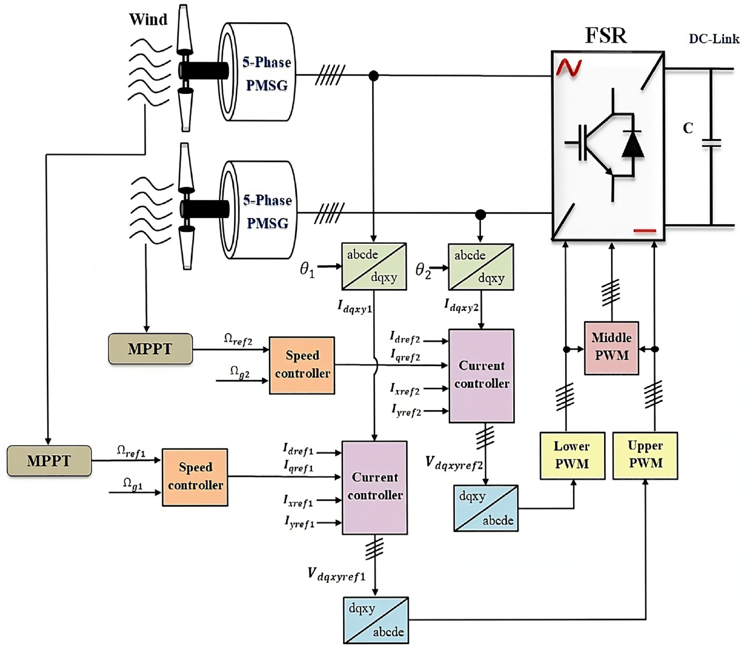
Figure 1 displays the general shape of the WPGS based on two five-phase PMSG connected on three-phase grid. The setting of new back-to-back converters are made up of two converters, the first is a MSC, it is a five-phase FSR, and the second transformer is a GSC) it is classical three-phase inverter, and the link between them is a filter C.
Wind-turbine modeling
The below equation offers a mathematical equation of the aerodynamic energy produced by wind turbines11,12:
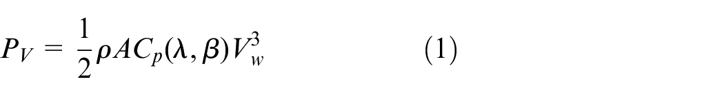
In order to calculate the energy generated by wind turbines, we depend on many significant coefficients, namely:
Where
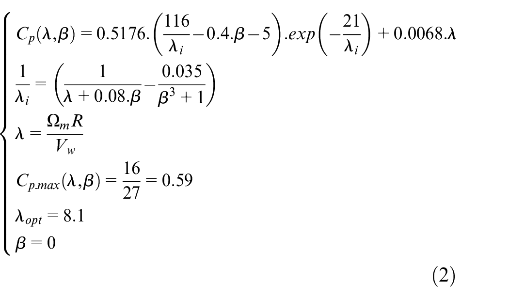
Whereas:
Modeling of the PMSG
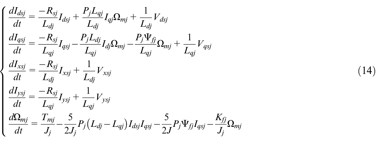
The voltage, magnetic flux, and electromagnetic torque for every five-phase PMSG model in a rotating d-q-x-y frame are expressed by equations (3)–(5), which are written in the following order 16 :
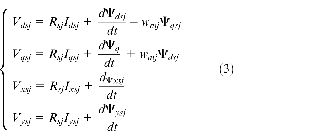
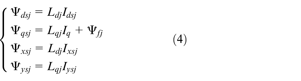
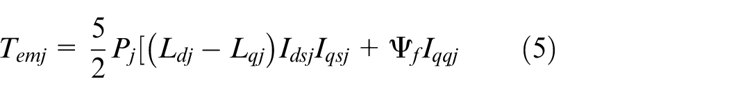
Where: d, q, x, and y are the axes of the stator, while
The wind-turbine system’s mechanical equation could be writing by the fundamental law of dynamic as ensue:
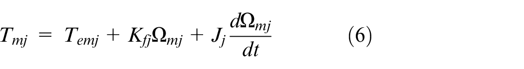
While:
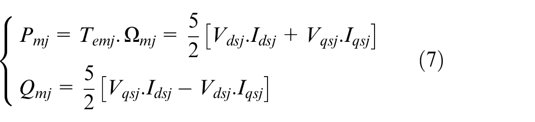
The power generated through each generator is able to be calculated using the formula that goes as follows
Analysis of the FSR topology
Figure 3 depicts that the FSR comprises five legs, with each leg containing upper, middle, and bottom switches. The FSR can be viewed as a combination of two five-phase rectifiers, each consisting of a set of switches. Specifically, the upper rectifier is made up of the top and middle switches, while the lower rectifier is composed of the middle and bottom switches. 16
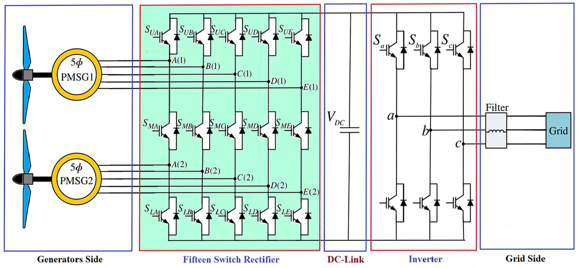
WPGS’s general architecture.
The upper and lower switches are controlled using traditional PWM to create their respective signals. The gating signals for the middle switches, on the other hand, are formed by inputting the gating signals of both higher and lower switches into the XOR logical operator. The overall number of switches is decreased by 25% when compared to a normal dual five-phase rectifier design.
The function of switch
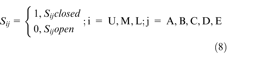
We may express the restrictions as:

Regarding the operational approach of this novel converter shown in Figure 3, it is possible to use three cases per leg. The switching states may be designated as 1, 0, and −1, as seen in Table 1. In this table, j corresponds to legs A, B, C, D, or E, while U, M, and L correspond to the upper, middle, and lower switches, successively.
State of switching and voltage between the rectifier’s poles in a fifteen-switch structure.
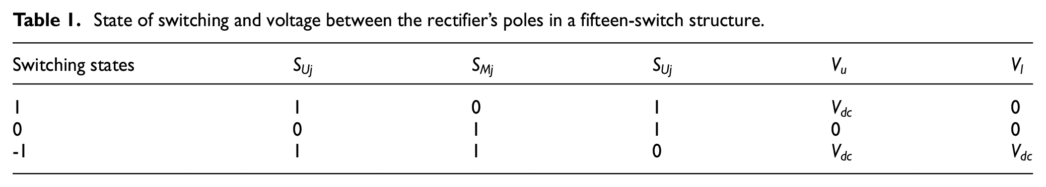
Figure 4 depicts the suggested PWM technique for the FSR, which utilizes two synchronized PWM units from traditional five-leg rectifiers. Each PWM unit receives distinct voltage references,
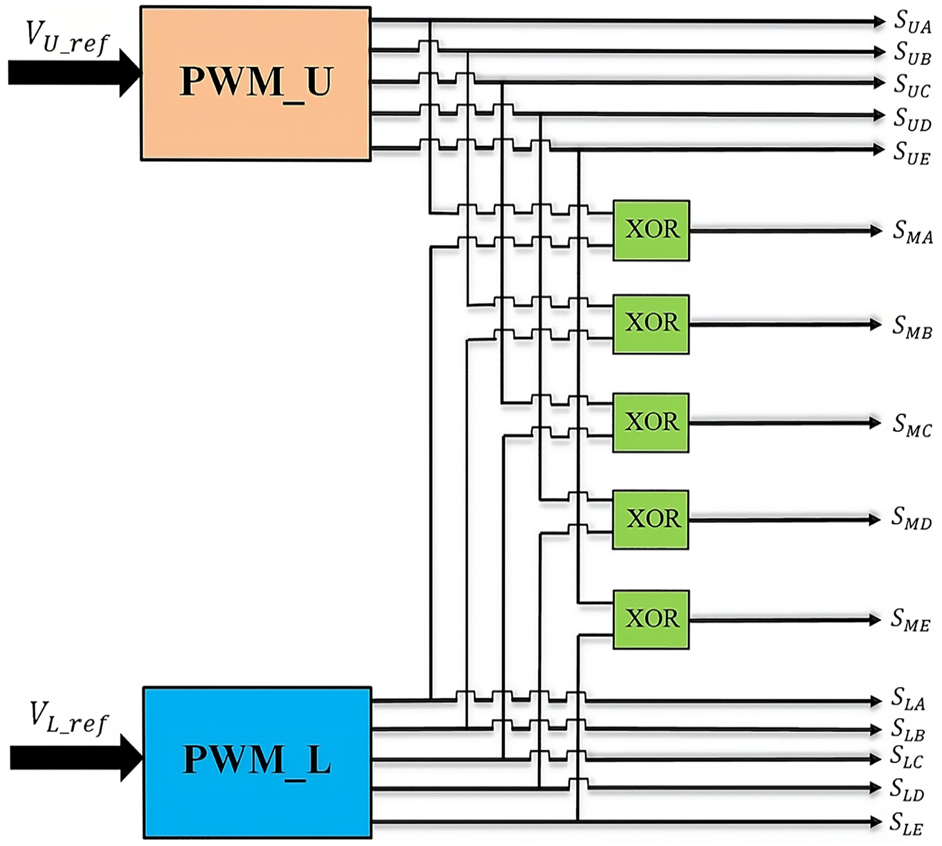
Proposed PWM for the FSR.
Grid model
The grid voltage in the Park frame (d, q) might be stated in the following way 41 :
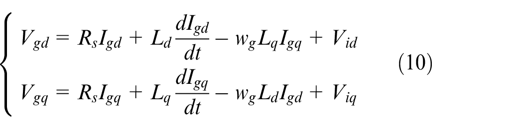
In the grid system,
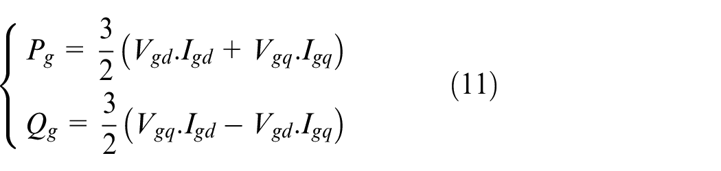
Within the context of the d-q reference frame, the active and reactive powers are expressed by
The control approach used for the GSC involves making
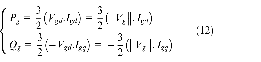
It may be concluded that the active and reactive power flows can be controlled by
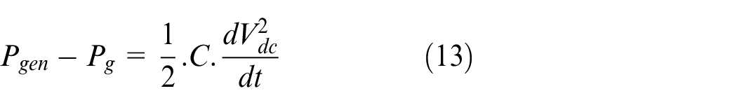
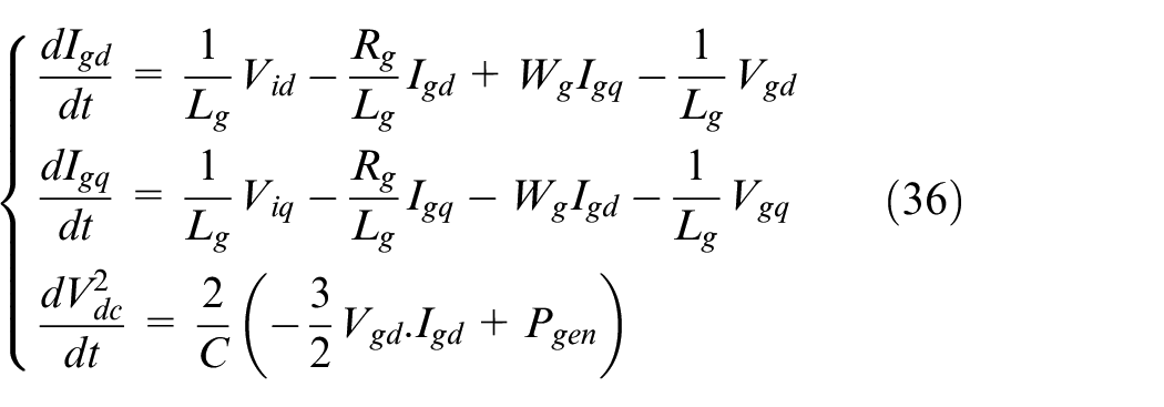
The DC-link provides a connection between the converter located on the generator side and the transformer located on the grid side. The dynamic demeanor of the DC-link voltage may be determined by considering power balancing and disregarding converter losses. 47
PMSG-based WPGS control
MSC control
BSC technique
The backstepping control methodology is based on the representation of interconnected systems as Lyapunov-order 1 subsystems, leading to heightened resilience against disturbances and improved overall system stability. The approach of BSC employs a sequential process, wherein a virtual command is generated at each stage to ensure the system’s convergence toward its equilibrium state (Figure 5). The utilization of a Lyapunov function ensures stability at every synthesis step.32,33 By applying the relationships described in equations (3)–(6), the state representation of the system can be expressed.
The general FSR control structure.
The implementation of BSC on the generator may be broken down into two consecutive steps. The first stage offers instructions for the subsequent one. Furthermore, the state vectors and control vectors are chosen so that
❖ Step1:
The tracking error’s state variable

The speed’s error dynamic is expressed in the following manner:

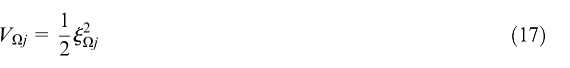
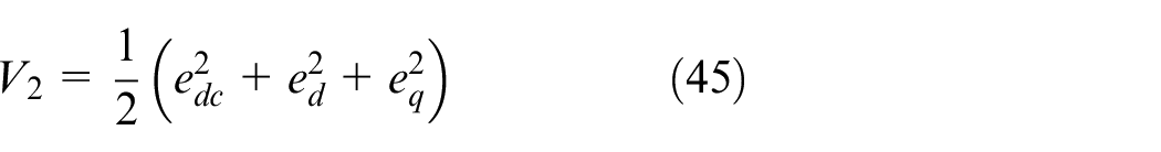
The primary aim of this first stage is to eliminate the error in speed tracking. We utilize the Lyapunov function, which is determined by the below relationship:
The Lyapunov function’s time derivative is given as:
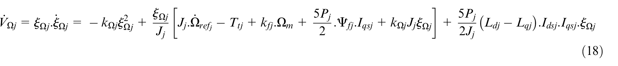
As part of the BSC design, the virtual inputs, referred to as stabilizing functions, are established by selecting the quadratic
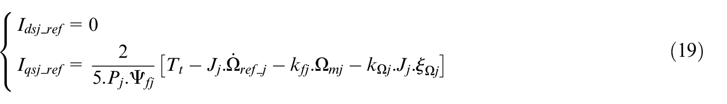
By substituting equation (19) into the derivative expression

❖ Step 2:
The system’s virtual inputs are
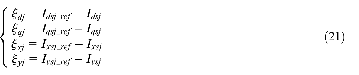
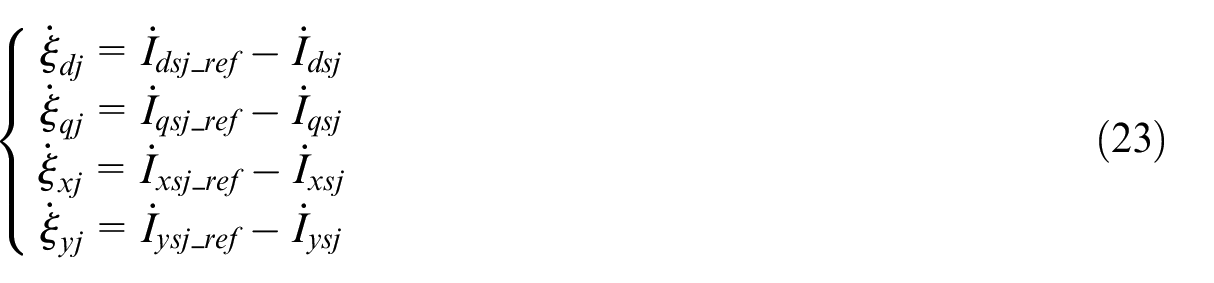
The errors in stator current can be expressed in the following form:
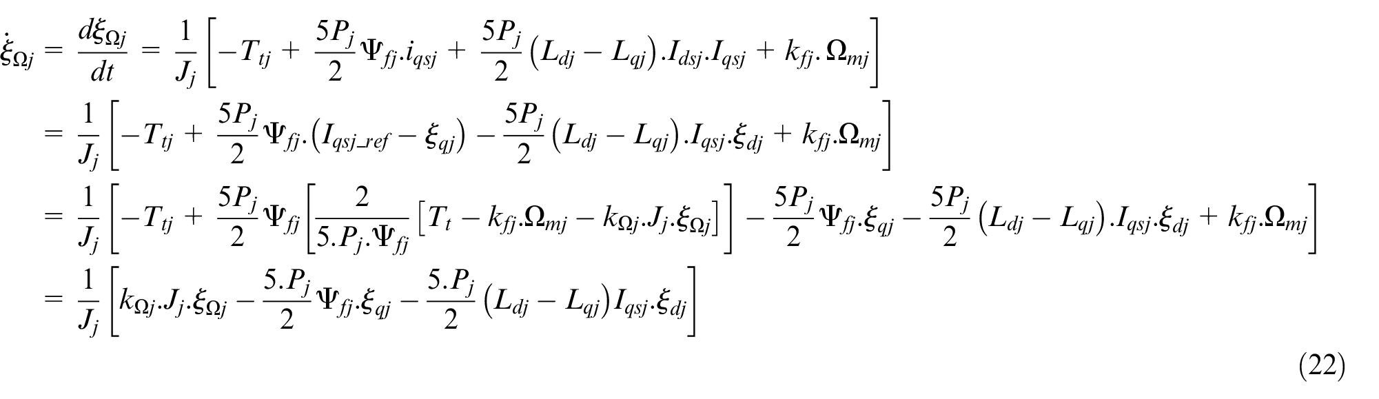
By utilizing equations (19) and (21), we can update the formula for speed dynamics to a new form.
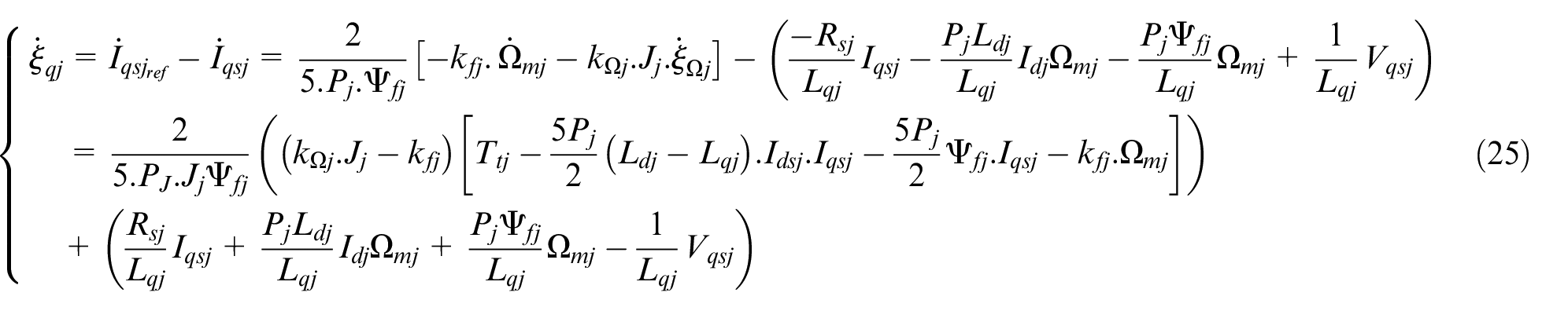
Formulae (14) and (25) might be used to express the dynamics of stator current errors.


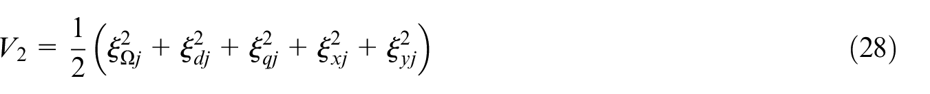
An innovative Lyapunov function is suggested to ensure the stability of the whole system by employing the stator voltages as references while considering speed errors and stator current errors.
The new Lyapunov function’s time derivative is given as:

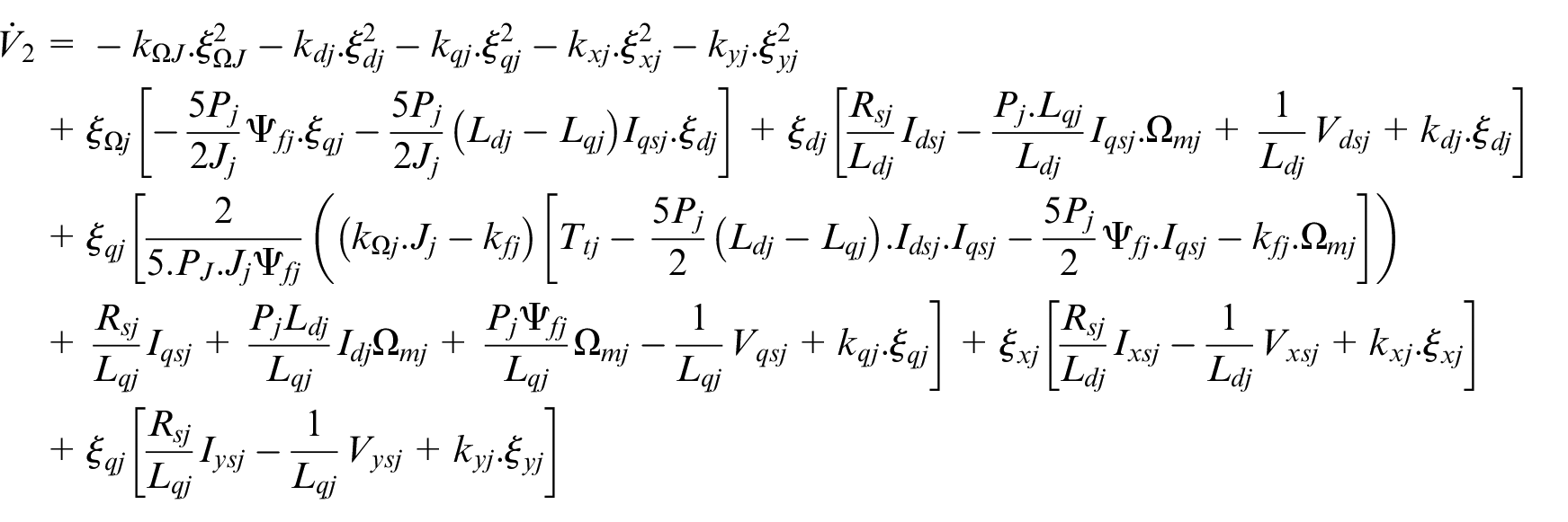
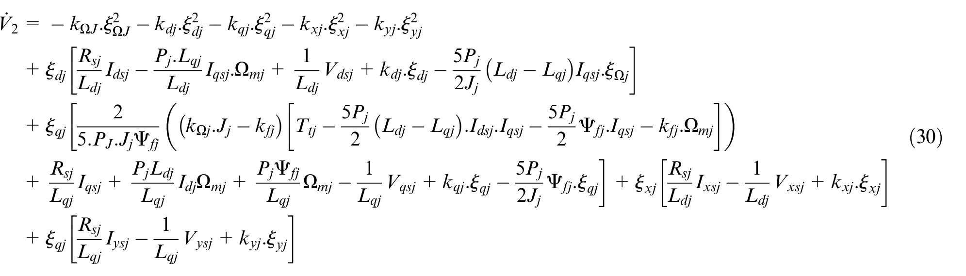
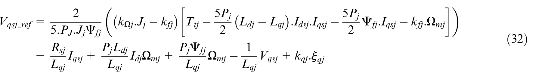
To ensure the negativity of the derivative of the Lyapunov function and achieve system stability, the stator reference voltages are applied in the following manner:


In simple terms, the behavior of the Lyapunov function may be summarized in the following way:

ANFIS technology
Description
ANFIS is an acronym for Adaptive Neuro-Fuzzy Inference System. This is a hybrid machine learning approach that combines the capabilities of neural networks with fuzzy logic systems. ANFIS is mostly used for modeling and control applications across many domains, including nonlinear control. The system employs a fuzzy inference technique to establish input-output correlations and adjusts the system’s parameters via the use of a neural network48,49
Figure 6 explains the ANFIS design. Regardless of the neural network component, it is identical to the fuzzy inference system. The ANFIS structure is comprised of five levels, which are delineated in the following order50,51:
The first layer, known as the input layer, consists of input variables. Each node inside this layer analyzes triangular, trapezoidal or Gaussian membership functions. The most optimal function is determined by the one that yields the lowest training error. The input variables are then sent to the subsequent layer.
Layer 2, known as the minimum selection layer, is in charge of determining the minimum value among the inputs provided. It performs the task of choosing the input with the minimum value among the available inputs.
Layer 3, known as the normalization layer, is responsible for normalizing every input concerning the other inputs. The output of node
In Layer 4, the value produced by the
Layer 5, designated as the summation layer, performs the task of aggregating all the incoming signals. The ANFIS architecture can be tuned to automatic tuning through the utilization of a least-square estimation method for output membership functions and a backpropagation algorithm for both output and input membership functions.

The ANFIS’s overall architecture.
ANFIS training
The Matlab/Simulink model was used to train ANFIS based on the nonlinear control technique (BSC) to control the WPGS to improve the system performance, improve the quality of the produced power, and reduce tracking errors. The stages of training this controller can be described through the following steps48,52–54:
The first step in the ANFIS training process contains the collection of training data, which is important for determining the inputs and outputs of the system. In this stage, the inputs are defined as speed error
The design phase of the Fuzzy Inference System (FIS): During this stage, the fuzzy sets and membership functions for every variable are established. This involves setting the appropriate membership functions and defining their forms based on the features and characteristics of each variable. The determination of membership function shapes is influenced by various factors, including the data distribution, the desired level of granularity, and the linguistic understanding of the variables.
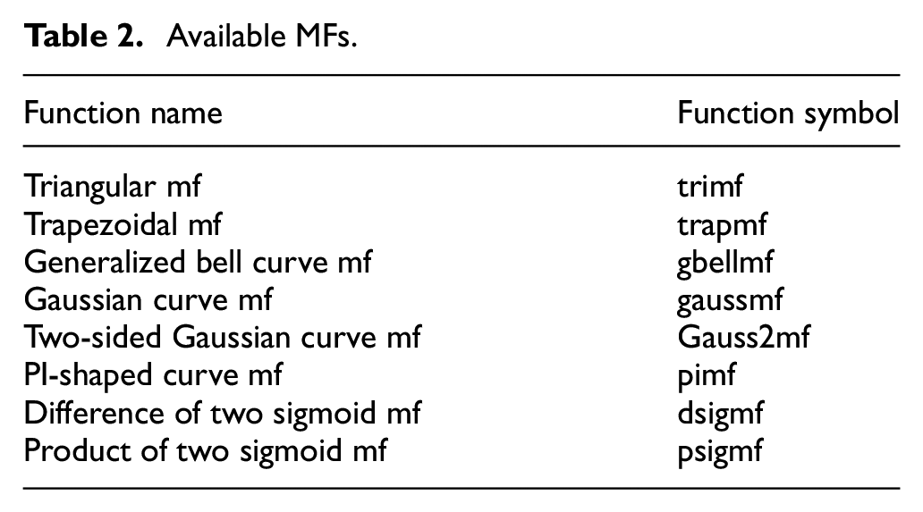
The Generate phase of Fuzzy Rules: To generate accurate and meaningful fuzzy inference results, it is necessary to establish a set of fuzzy rules that describe the relationship between the inputs and outputs. This is accomplished by analyzing the patterns and relationships within the data. The algorithm identifies clusters and generates fuzzy rules that capture the underlying structure and behavior of the system. The (trimf) membership function was chosen for the ANFIS model due to its superior performance in comparison to other alternatives (Table 2), which is a critical point to emphasize. Additionally, the optimal number of membership functions is determined by selecting a specific number of MFs (Figure 7).
Available MFs.
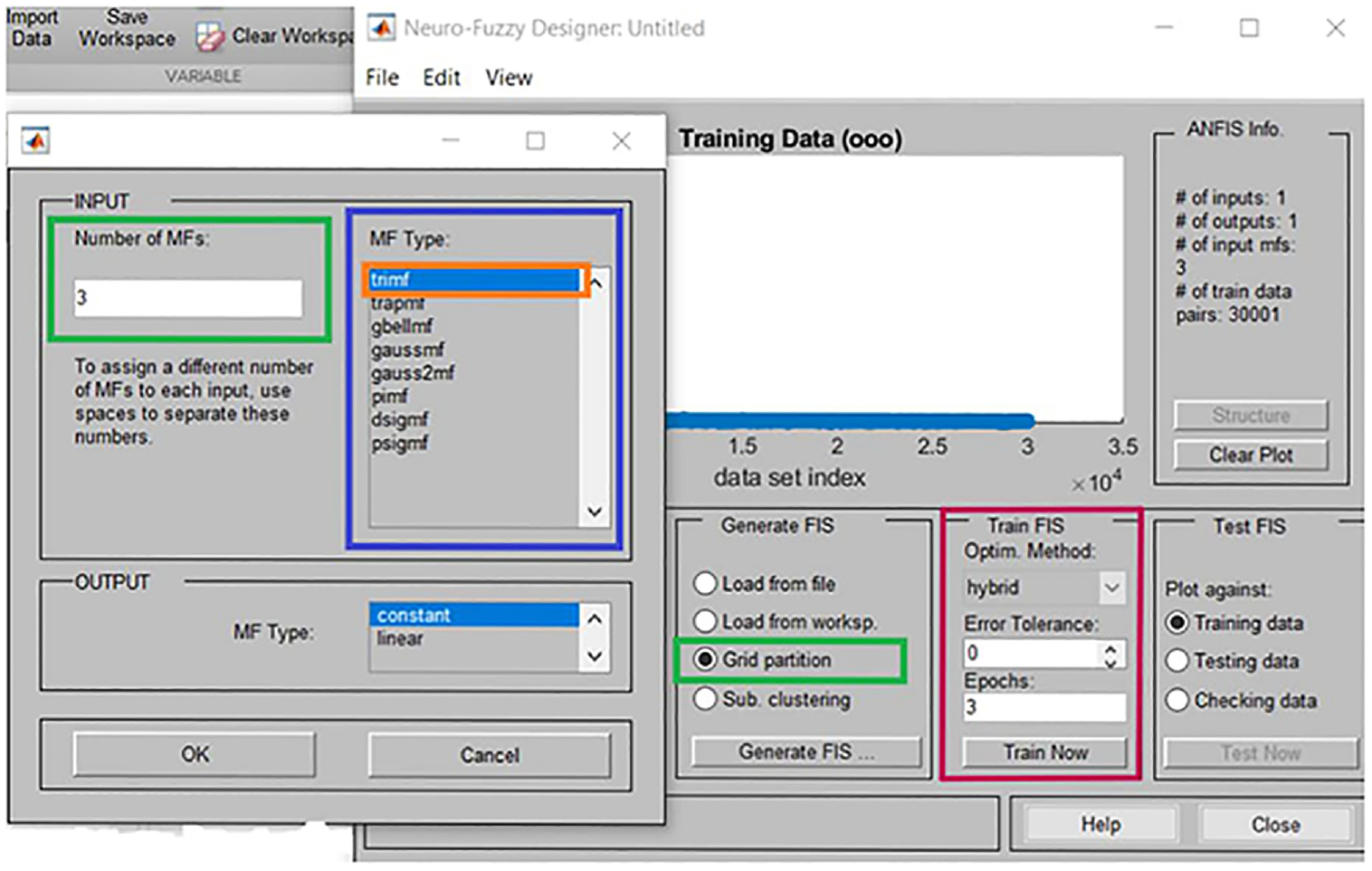
ANFIS model training interface.
The training phase of the ANFIS model: During this stage, specific algorithms, such as the backpropagation algorithm and the hybrid learning algorithm are utilized to repetitively tune the parameters of the model. This process aims to reduce the disparity between the anticipated outputs produced by the ANFIS model and the actual outputs acquired from the training data. By fine-tuning the model’s parameters using these training algorithms, the ANFIS model becomes more precise and capable of effectively capturing the essential patterns and relationships within the data. The objective is to achieve the optimum possible level of concurrence between the predicted outputs and the real outputs.
GSC control
BSC technology
The grid-side converter (GSC) controls the distribution network’s electrical energy flow. The DC bus voltage and power factor stability are the goals of this regulation.45,47
Based on the relationships (10) and (13) can be written the state form of this system as follows:
The implementation of backstepping control on the grid side may be broken down into two consecutive steps. The first stage offers instructions for the subsequent one. Furthermore, the state vectors and control vectors are chosen so that
Step 1:
The tracking error’s state variable
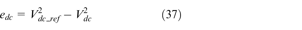
Due to the fact that our objective necessitates that the error converges to zero, we are able to fulfill it by selecting
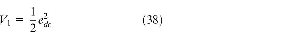
The Lyapunov function’s time derivative is given as:
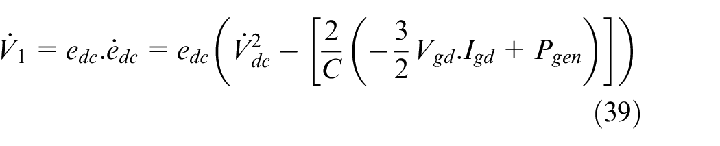
As part of the BSC design, the virtual input, referred to as the stabilizing function, is established by selecting the grid’s current
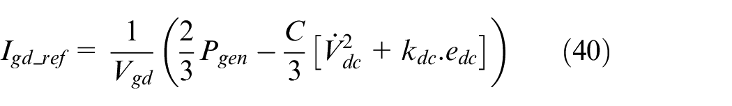
By substituting equation (40) into the derivative expression

Step 2:
The system’s virtual inputs are
The errors in grid currents can be expressed in the following form:
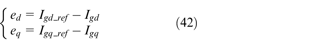
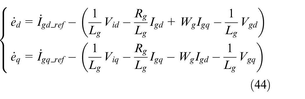
Therefore, the equation for the error may be written as follows:
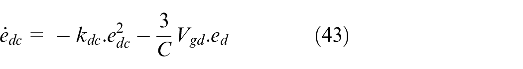
Moreover, the dynamic equation for the error signals
An innovative Lyapunov function is suggested to ensure the stability of the whole system by employing the voltages
The novel Lyapunov function’s time derivative is given as:

So:
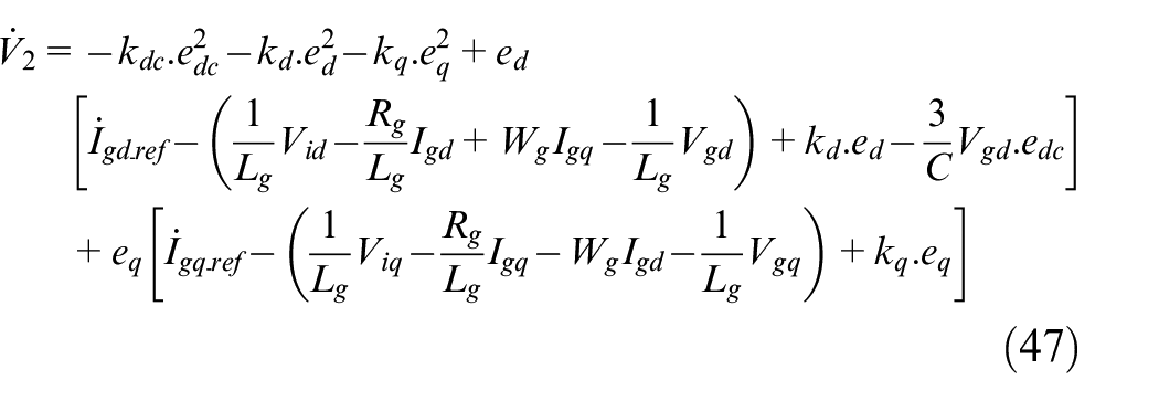
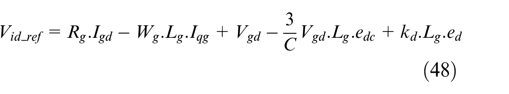
To ensure the negativity of the derivative of the Lyapunov function and achieve system stability, the stator reference voltages are applied in the following manner:

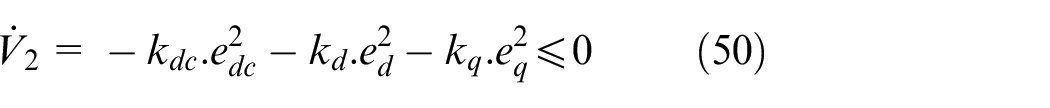
Ultimately, the behavior of the Lyapunov function might be described as outlined below:
ANFIS control technique
The process of training the ANFIS for grid-side converter control based on BSC involved following similar steps to those used for generator and machine-side converter control. Nevertheless, there are differences in terms of the inputs and outputs of the system.
Three variables were specified for the inputs. The first input indicates the error in the DC-bus voltage (
Regarding the outputs, there are three outputs. The first output is the reference value of the current
Using these inputs and outputs to train the ANFIS model based on the BSC method, the system can learn and adapt to reduce the differences between what it should do and what it does. The ANFIS model can make accurate control signals and reference values thanks to this training process. This makes sure that the grid-side converter is controlled efficiently and reliably.
Results and discussion
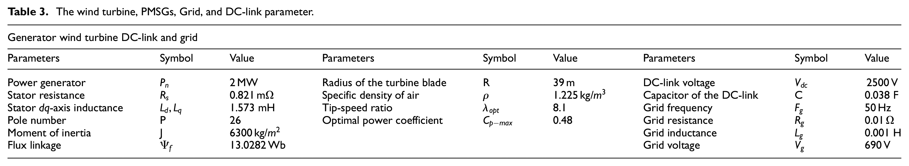
To assess the efficaciousness of control strategies, as explained in this scholarly paper, and to demonstrate their efficiency, the described approaches were tested through experiments under various wind speed profiles, which can be seen in Figures 5 and 8. Simulation experiments were conducted using the MATLAB/Simulink program. The numerical simulations utilized a reactive power reference of
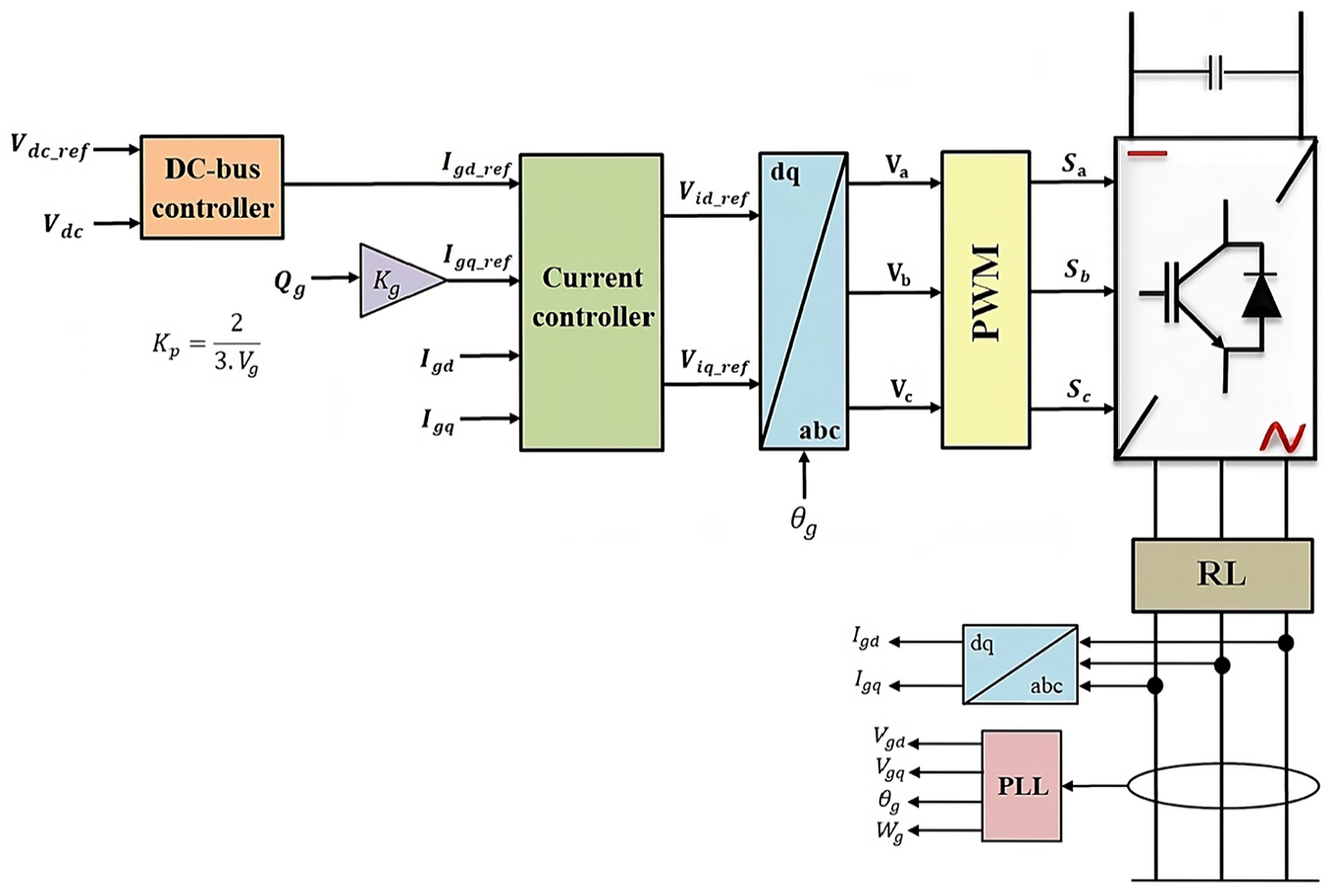
The general GSC control structure.
The wind turbine, PMSGs, Grid, and DC-link parameter.
MSC outcomes
The performance assessment of the generation system is carried out under different wind velocities, with an average velocity of 10.5 m/s, as depicted in Figure 9(a). The study is conducted at a rotating angle of 0°. The utilization of the ANFIS method produces virtually ideal values with a minimal error rate for both TSR (
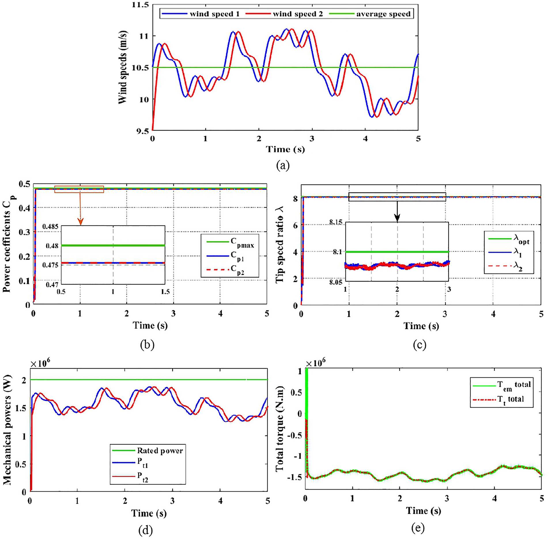
Simulation outcomes of the two PMSG wind systems controlled by ANFIS-BSC: (a) wind speed profile, (b) power coefficients, (c) tip speed ratio, (d) mechanical powers, (e) total electromagnetic torque.
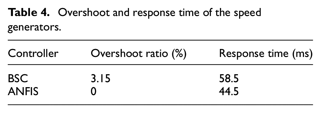
Figure 10 displays the mechanical speed of the generators in comparison to the reference speeds. Both control approaches demonstrate strong performance in accurately following the reference values. The superiority of the ANFIS method over BSC is evident, especially in closer observation where ANFIS shows a stronger adherence to the desired reference values.
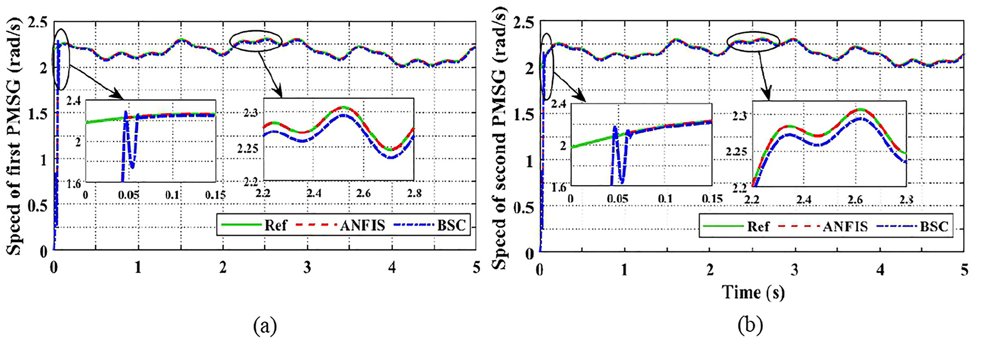
Comparative analysis between the ANFIS and BSC controllers: (a) the speed of the first generator and (b) the speed of the second generator.
The following Tables 4 to 7 summarizes the highlights and key findings that are demonstrated in Figure 10.
Overshoot and response time of the speed generators.
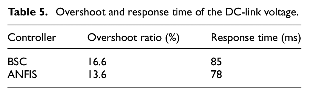
Overshoot and response time of the DC-link voltage.
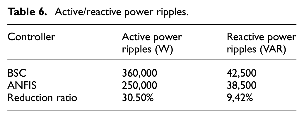
Active/reactive power ripples.
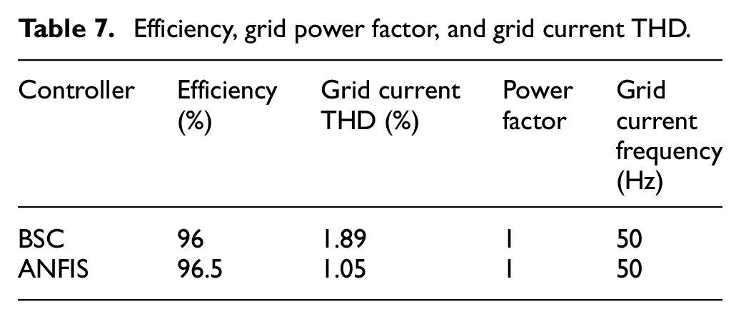
Efficiency, grid power factor, and grid current THD.
GSC results
Figure 11 illustrates a comparative examination of the outcomes on the grid side, specifically comparing the ANFIS and the BSC controller. The key findings of this study include an analysis of the DC-bus voltage, injected powers, power factor, grid frequency, a detailed examination of grid voltage and current waveforms, a closer examination of single-phase grid current, and an evaluation of the THD ratio of grid current. Figure 11(a) and (b) demonstrate that the DC-link voltage stays consistent, irrespective of variations in wind speed. The ANFIS has a clear advantage over BSC in terms of both the rate of overshoot and the time it takes to respond. The ANFIS technique exhibits improved performance by decreasing overshooting and delivering quicker response times in comparison to the BSC approach. Figure 11(c) and (d) illustrate the active and reactive power that is being injected into the network, respectively. The active power exhibits responsiveness to changes in wind speed while maintaining accurate alignment with the reference value. Nevertheless, it is important to mention that the ANFIS demonstrates a somewhat higher level of effectiveness in reducing ripples when compared to the BSC technique. In contrast, the reactive power maintains close adherence to its reference value of zero in order to attain a power factor of unity, as seen by Figure 11(e) and (g). Figure 11(i) displays the THD ratio, demonstrating that both control strategies produce excellent outcomes. However, ANFIS exhibits higher performance compared to the BSC.
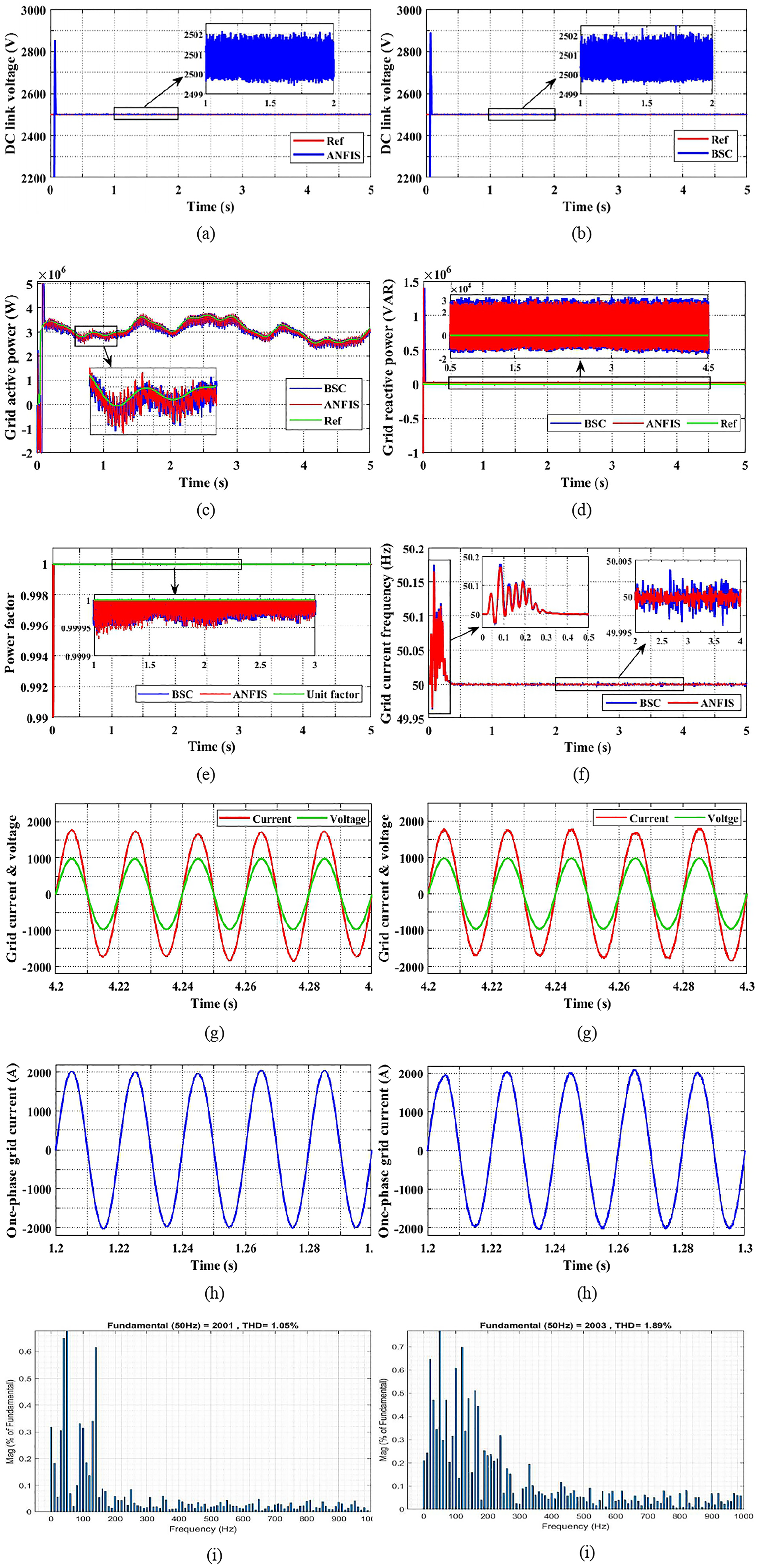
Comparative study of GS results between the ANFIS and BSC: (a, b) DC-bus voltage; (c) active power injected into the grid; (d) grid reactive power; (e) power factor; (f) grid frequency; (g) closer examination of grid current and voltage; (h) closer observation of grid current; and (i) the overall harmonic distortion of grid current.
The following Tables 4 to 6 summarizes the highlights and key findings that are demonstrated in Figure 11.
To evaluate the efficiency of the control systems under investigation, the theoretical output power is compared to the actual power being injected into the network (Figure 12), as defined in the following:
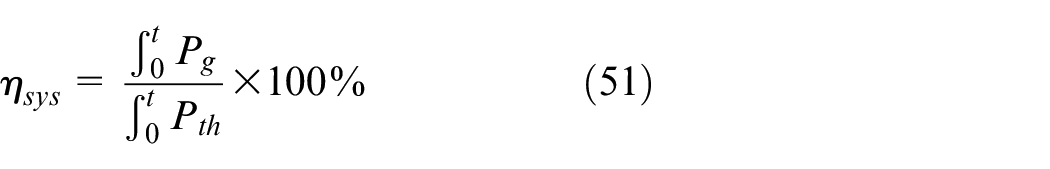
Where:
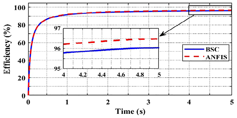
Overall efficiency of the system.
Conclusion
This article discusses the implementation of BSC and ANFIS control technologies for a grid-connected wind system. This wind system is based on two five-phase PMSGs that are controlled by a FSR. The ANFIS control was trained using BSC, which is based on Lyapunov theory, to guarantee system stability. This control method is well-known for its intrinsic benefits, including simplicity, high accuracy, and stability. Comprehensive simulations are conducted to evaluate the efficaciousness of the suggested control techniques and compare their outcomes with each other.
The outcomes of the simulations displayed that both techniques achieved separate control between the PMSGs. They also showed several enhancements in both the rapid responses and the steady-state effectiveness. These improvements encompass rapid response, precision, and ripple reduction. Notably, the ANFIS control approach has exhibited several good advancements when compared to the BSC technique. Key enhancements include faster rising time, excellent speed tracking without overshoots, and fewer ripples in injected power into the grid.
The objective of incorporating the fifteen-switch converter (FSR) into the wind system is to optimize its efficiency by lowering the overall number of switches compared to the conventional system, which is based on two parallel rectifiers, thus reducing losses associated with switching while keeping the control of the system simple. The results indicate that the suggested topology is very successful in providing outstanding performance under both steady-state and transient circumstances.
Footnotes
Abbreviations
WPGS Wind Power Generation System
5-ph PMSG Five-phase Permanent Magnet Synchronous Generators
BSC Backstepping Control
ANFIS Adaptive Neuro-Fuzzy Inference System
GSC Grid-Side Converter
MSC Machine-Side Converter
FSR Fifteen-Switch Rectifier
MPPT Maximum Power Point Tracking
FSWPGS Fixed Speed Wind Power Generation System
VSWPGS Variable Speed Wind Power Generation System
BTBC Back-To-Back Converter
PWM Pulse Width Modulation
TSR Tip Speed Ratio
THD Total Harmonic Distortion
Acknowledgements
All contributors to the editing of this article are mentioned.
Author contributions
A.S conceived the original idea. These were also discussed with all authors discussed and agree with that main focus and ideas of this paper.
The simulations were performed by A.S. the main ideas behind the simulation were conceived by other authors.
This paper was written by A.S and he’s been mentored by all other authors in how to write, view, and analyze the results.
Declaration of conflicting interests
The author(s) declared no potential conflicts of interest with respect to the research, authorship, and/or publication of this article.
Funding
The author(s) received no financial support for the research, authorship, and/or publication of this article.
Available of data and materials
All data generated or analyzed during this study is included in this article.