
Abstract
This paper introduces a novel hybrid method for achieving Maximum Power Point Tracking (MPPT) in a photovoltaic-diesel-battery hybrid water pumping system driven by an induction motor drive (IMD). The innovative MPPT control strategy uniquely combines the rapid response and minimal oscillations of the Adaptive Neuro Fuzzy Inference System with the high robustness of Robust Terminal Sliding Mode Control (RTSMC). This combination ensures unprecedented steady-state resilience to changes in solar irradiance, enhancing system stability across a variety of IMD speeds, and making the system robust to parameter variations. Unlike traditional approaches, this two-stage photovoltaic (PV) setup integrates a regulated boost converter for MPPT control and a three-phase inverter using Space Vector Pulse Width Modulation (SVPWM) to regulate the DC link voltage (Vdc). Extensive MATLAB Simulink simulations demonstrate the proposed method’s superior efficiency in power extraction and its resilience under varying operating conditions, showcasing its originality and effectiveness.
Introduction
Tunisia, like many other countries, is experiencing a rising demand for electricity due to population growth and increased industrialization. However, conventional sources of energy are becoming scarce, necessitating the adoption of renewable energy solutions to bridge the supply-demand gap. Among these, solar energy is the most viable option due to its abundance, inexpensive costs of installation, and environmentally friendly design. In Tunisia, a significant electricity share is consumed by the agricultural sector, specifically for water pumping. Thus, a solar-powered water pumping system, consisting of PV panels, a pump system with electric motors, inverter units, a diesel generator, and battery backup, is a superior alternative for powering motors in water-pump systems.
The use of solar PV-powered irrigation pumps offers numerous advantages, including increased system reliability and lower operational and maintenance costs, as stated in reference. 1 However, motor drive systems that rely solely on power from the PV array can experience difficulties operating smoothly in response to fluctuating solar insolation levels, as noted in reference. 2 To optimize solar energy production and water pumping while accounting for variations in PV power, it is essential to consider all probability states. 2 To address this challenge, a two-stage topology can be implemented, which utilizes a DC-DC converter to MPPT control and extrapolate the PV’s maximum power. In contrast, a three-phase voltage source inverter (VSI) mainly controls the Vdc,3,4 finally a diesel generator with an AC/DC converter can be added as another source to provide backup power to the system during periods of low sunlight or power outages. Compared to single-stage and two-stage solar PV systems, this two-stage structure is better equipped to regulate the Vdc at a fixed value. It offers improved dynamic response regardless of solar irradiance levels. 5 Additionally, it provides supply continuity during periods of low sunlight or power outages, which significantly enhances the reliability of the system.
In recent years, researchers have committed their time to creating effective MPPT techniques capable of swiftly and accurately determining the optimal operating point for solar power systems. The objective is to minimize power losses and ensure effective operation under varying and uncertain conditions. 6 The MPPT techniques have been driven by the need to enhance the accuracy, efficiency, and the consideration of many factors such as ease of use, convergence speed, specific implementation, required sensors, cost-efficiency, and adaptability.7,8 A wide range of techniques has been proposed over the years, encompassing both conventional methods like Constant Voltage (CV), 9 Fractional Open Circuit Voltage (FOCV), 10 Fractional Short Circuit Current (FSCC),11,12 Look-up Table (LUT), 13 Perturb and Observe (P&O), 14 and Incremental Conductance (INC), 14 offer simplicity but may suffer from slow convergence and oscillations around the MPP, especially under changing weather conditions. To address these limitations and achieve faster, more accurate MPPT, research has shifted toward intelligent control techniques. Prominent examples include Model Predictive Control (MPC), 15 Fuzzy Logic Control (FLC), 14 Radial Basis Function Neural Network (RBFNN), 16 and Neural Networks (NN). 14 FLC offers faster tracking and reduced fluctuations compared to conventional methods, but it can be sensitive to environmental changes and requires accurate system knowledge. NNs provide improved stability around the MPP, but training them can be time-consuming, and their inner workings are often difficult to interpret. The integration of NNs and FLCs has led to a more robust and intelligent method: Adaptive Neuro Fuzzy Inference Systems (ANFIS). 17 ANFIS-MPPT offers fast responses and minimal oscillations due to its ability to adapt quickly to changing weather conditions. However, obtaining accurate data for training and fine-tuning the ANFIS controller can be challenging. Researchers are also exploring algorithms inspired by natural phenomena, such as Ant Colony Optimization (ACO) 18 and Particle Swarm Optimization (PSO).19,20 The Butterfly Optimization Algorithm (BOA) 21 is another emerging technique that utilizes principles inspired by butterfly foraging behavior to achieve efficient MPPT. Due to the inherent nonlinearities of PV modules and power converters, nonlinear controllers are becoming increasingly popular for achieving MPPT in PV systems. Widely adopted strategies for robust tracking include Sliding Mode Control (SMC), 22 backstepping (BS), 23 and synergetic approaches. 24 While purely intelligent techniques like ANFIS and NN offer advantages, they can struggle with system nonlinearities. To address this, research is exploring hybrid approaches that combine the strengths of intelligent techniques with established nonlinear control theories. These hybrid approaches have the potential to achieve superior performance, such as Neuro-Fuzzy network-based robust integral backstepping 25 and Neural network-based adaptive global sliding mode, 26 offer the potential to achieve superior performance.
To overcome the conventional MPPT techniques limitations and harness the benefits of AI-based and nonlinear control theories-based MPPT, this study proposes a novel MPPT approach that combines ANFIS with RTSMC, and field-oriented control technique based on SVPWM for efficient induction motor control in a hybrid PV-Diesel-Battery water pumping system. The ANFIS is employed due to its fast response, low oscillations, and guaranteed stability. It tracks the reference maximum power voltage (MPV) within a two-stage MPPT control scheme.27,28 In the first stage, ANFIS establishes the PV array’s MP reference. It utilizes fuzzy inference rules to adjust the membership function until the error is minimized and the desired output voltage is achieved. The second stage introduces RTSMC to ensure the system reaches the optimal voltage reference and maintains control over the boost converter’s duty cycle. The ANFIS-MPV reference search and PV voltage (Vpv) tracking are continuously repeated until maximum power is attained. This approach offers several advantages over conventional MPPT techniques like INC and P&O. Unlike these methods, which may not guarantee convergence stability, the proposed ANFIS-based MPPT offers improved accuracy and robustness against external disturbances and uncertainties. Traditional MPV-based techniques can also suffer from power oscillations around the Maximum Power Point (MPP), impacting control outcomes. An effective MPPT method should precisely locate the MPP under varying operating conditions, and the proposed ANFIS-MPV approach excels in this aspect. However, SMC is employed in the second stage due to its well-established benefits, including stability, excellent transient response, and ease of implementation. SMC-based MPPT algorithms are generally categorized into traditional and advanced types. Traditional methods often rely on first-order sliding mode control derived from P&O, INC, or linear expressions. Advanced SMC techniques are classified as innovative, including those utilizing Terminal Sliding Mode Control, Super Twisting Theory, and integration with Artificial Intelligence (AI) algorithms. 8 Compared to traditional methods, TSMC offers faster convergence and improved robustness against disturbances due to including a nonlinear fractional power term in the sliding variable. The combination of SMC with AI algorithms for MPPT is an active area of research, focusing on reference signal generation or controller parameter optimization. Considering the importance of tracking accuracy in MPPT design, TSMC emerges as the most suitable technique for the second stage of the ANFIS-MPV approach. This work leverages the strengths of both ANFIS and TSMC to develop a robust MPPT solution for standalone PV power generation systems. During the first stage, the system identifies the optimal MP point corresponding to various solar radiation and temperature values using the established linear relationship between the ideal and open-circuit voltages. Subsequently, the second stage utilizes TSMC to drive the system toward the MPV reference via a DC/DC boost converter.
Recently, water pumping systems powered by solar PV have witnessed a shift from the traditional DC motor to the induction motor (IM) due to its robust mechanical design and little need for maintenance. As contrasted with the frequently utilized permanent magnet DC motor, the IM delivers improved performance. Under particular conditions of load, the IMD functions as a motor with a fixed speed, offering the flexibility to control its speed across a wide range of loads. Various methods have been extensively studied to achieve induction motor drive control without relying on sensor feedback. Among these methods, the observer-based approach has gained attention. However, it should be noted that this method may exhibit some imprecision degree due to its reliance on machine parameters. Additionally, instability issues may arise when operating at low speeds.29,30 Alternatively, enhanced performance can be attained by employing techniques such as the extended sliding mode 31 and speed predictions using the Kalman filter. Nonetheless, the inherent nonlinearity of the system poses a challenge to the effectiveness of these approaches.32,33 A reliable method for establishing consistent speed control over a wide range of speed fluctuations is the use of NN. Speed estimate systems based on Model Reference Adaptive Systems (MRAS) perform better than other approaches in many aspects, especially in terms of ease of implementation. 34 There have been several other MRAS-based methods investigated in the literature, including instantaneous reactive power-based, back-EMF-based, stator current, and active power-based. 35 An improved MRAS strategy 36 based on instantaneous reactive power is used in this situation.
The article is structured as follows: Section 2 details the system configuration, encompassing the PV panel, diesel generator, battery, and motor. Section 3 outlines the control architecture, emphasizing the integration of ANFIS and RTSMC strategies. In Section 4, we present empirical results and engage in discussions that highlight the potential of our approach to optimize energy production and utilization.
Two-stage hybrid system design
Figure 1 depicts our water pumping system which combines solar PV arrays with a two-stage power conversion mechanism. There is a boost DC-DC converter in the first stage, it is paired with a new hybrid ANFIS and terminal sliding mode MPPT algorithm to operate at the MPP to convert the PV array voltage into a higher Vdc level. In the second stage, the high DC voltage is transformed into a three-phase AC voltage, which is fed to an inverter module using a three-phase VSI with SVPWM scheme to optimize Vdc utilization. The detailed designs of the various components of the system are mentioned in the subsections below.
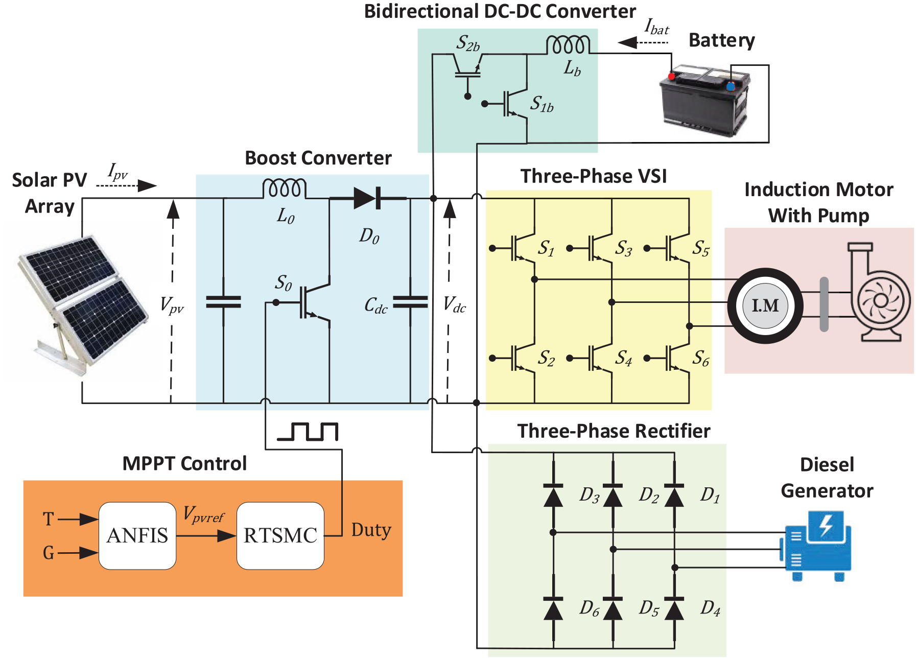
System diagram for the PV/battery/diesel-fed IMD.
Moto-pump unit
In the process of selecting an induction motor for a water pump, it is crucial to consider the required water delivery rate. To approximate the power rating of the hydraulic pump, a reliable method described in references37,38 can be employed. Firstly, the hydraulic coefficient (Ch) is calculated by multiplying the acceleration due to gravity (g) by the density of the fluid being pumped (δ):

Subsequently, the power consumption Pe of the motor is determined using the following formula, where Qj represents the water flow rate (measured in m3/h), HMT denotes the total dynamic head of the system (measured in meters), and ηmp represents the pump efficiency:

These calculations provide valuable insights into the selection process, ultimately leading to the choice of a 4 kW (5.4 hp) induction motor, which is well-suited to effectively power the water pump.
Photovoltaic solar panel array
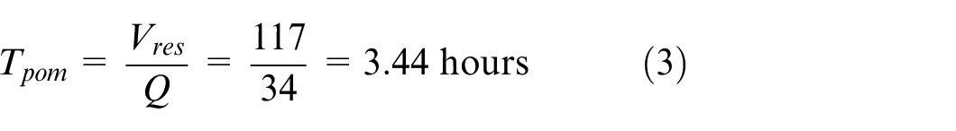
The PV module sizing can be based on production or consumption. In this case, we sized it based on the consumed electrical energy (Eel) during the pumping time (Tpom) required to fill a reservoir with a volume of 117 m3.

Then, we deduce the energy produced (
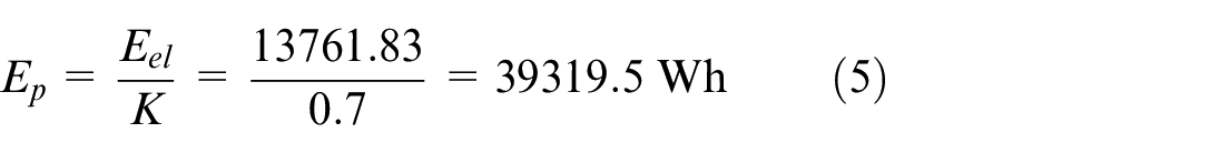
Where K is the correction coefficient ranging from 0.55 to 0.75. then, the peak power (
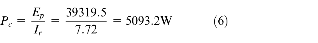
Where, Ir is the average daily irradiation, estimated in our region (Tunisia) to be 7.72 kWh/m2/d.
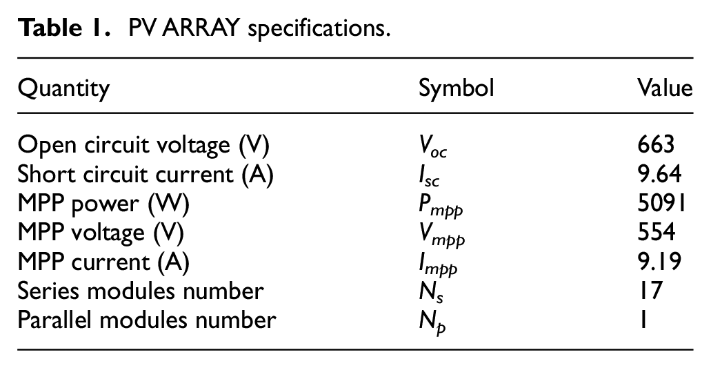
Table 1 summarizes the ratings of the PV array used in the hybrid water pumping system.
PV ARRAY specifications.
Steady DC link voltage determination
The formula below can be used to determine the optimal steady state voltage:
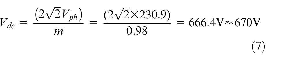
The values for some parameters are provided in equation (7), which include a motor phase terminal voltage of (Vph) = 230.9 V, and a modulation index (m) of 0.98. Based on these values, the Vdc utilized in the system amounts to 670 V.
DC link capacitor selection
To ensure that the voltage remains stable under varying load and irradiance conditions, the design standard for a DC link capacitor is established, and its value is determined as:
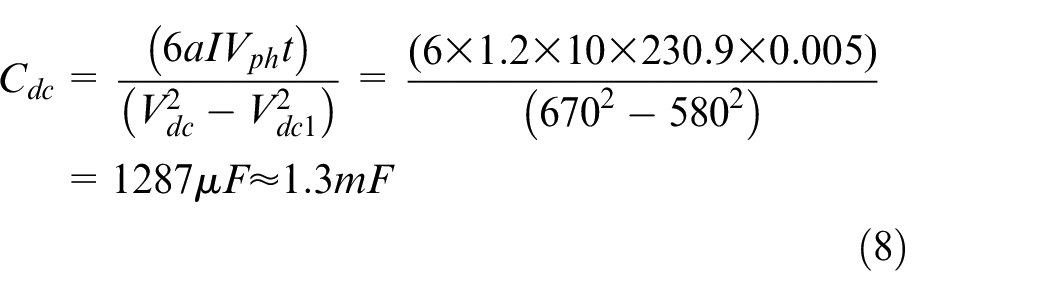
In (8), the lowest allowable Vdc under variable conditions (Vdc1) is 580 V, and during the Vdc is 670 V. The motor’s phase terminal voltage (Vph) is 230.9 V. With a motor current I of 10 A, a = 1.2, and t = 5 ms, The DC link capacitor should be set at its ideal value which is calculated as 1.3 mF, taking into consideration all transient conditions.
Boost converter inductor selection
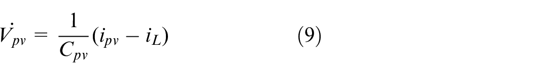
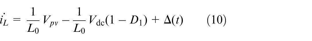
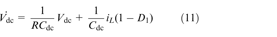
The dynamic equations of the boost converter are created by employing the average method with the PV array, demonstrated as follows:
The governing equation given below, is used to calculate the boost converter’s duty cycle.

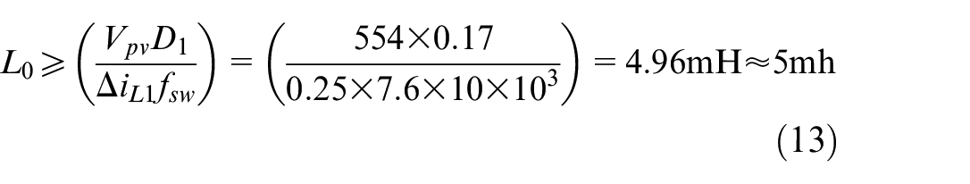
The boost converter’s inductor L0 is designed to handle the current ripple percentage by utilizing the duty cycle D1 as follows:
Bidirectional converter (BDC) inductor selection
The BDC’s operating duty ratio is acquired in a way that resembles the boost DC-DC converter and is expressed as:
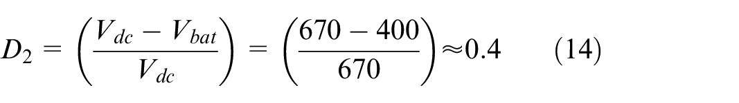
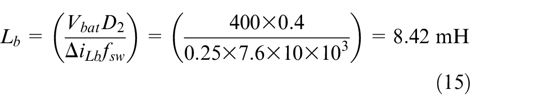
The D2 value is used as a reference to determine the appropriate inductor Lb for the BDC, as given by the equation (15).
Hybrid system control diagram
This section presents the control diagram employed in the water pumping system based on IMD powered by a combination of PV panels, batteries, and a diesel generator. Figure 1 shows the detailed control block diagram, which encompasses (ANFIS-RTSMC) MPPT control to optimize power extraction from the PV array by regulating the boost converter, Motor-side control employing SVPWM in a field-oriented control scheme, through a BDC, two-loop current-mode control is used to govern battery functioning, and an AC/DC converter, that converts the AC voltage from the diesel generator into DC voltage, which is then integrated into the DC link. More specificities of these control systems are provided below.
MPPT design
In this section, we present the proposed MPPT design, which is based on a hybrid approach that combines an ANFIS and a RTSMC. The MPPT design is divided into two main parts: Reference voltage generation using the ANFIS Algorithm, and RTSMC.
Reference voltage generation using the ANFIS algorithm
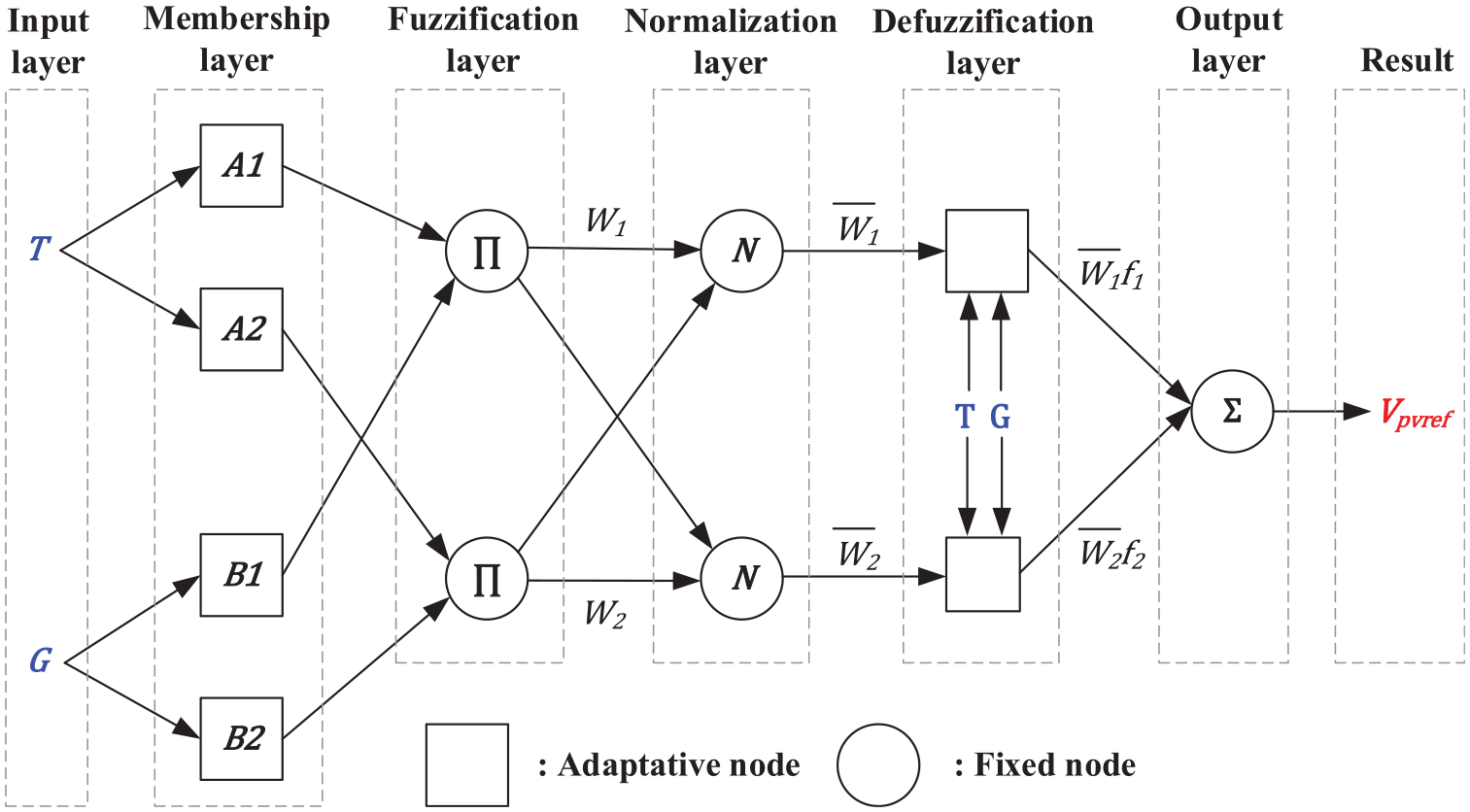
The Neuro-Fuzzy Algorithm combines the benefits of NN and the model of Takagi and Sugeno (TS). This approach provides an excellent representation of knowledge through fuzzy systems and enhances system performance due to the learning capabilities of neural networks. As illustrated in Figure 2, five layers are involved in this algorithm: Fuzzification, Rules, Normalization, Consequences, and Addition, 39 adaptive sections are represented by square nodes, whereas non-adaptive sections are denoted by circular nodes. Temperature and irradiance are inputs to the neuro-fuzzy network, which assigns each parameter three Gaussian membership functions., with a corresponding linear equation assigned to every rule in the output layer and generates a reference voltage (Vpvref) for peak power. 25
Reference voltage generation.
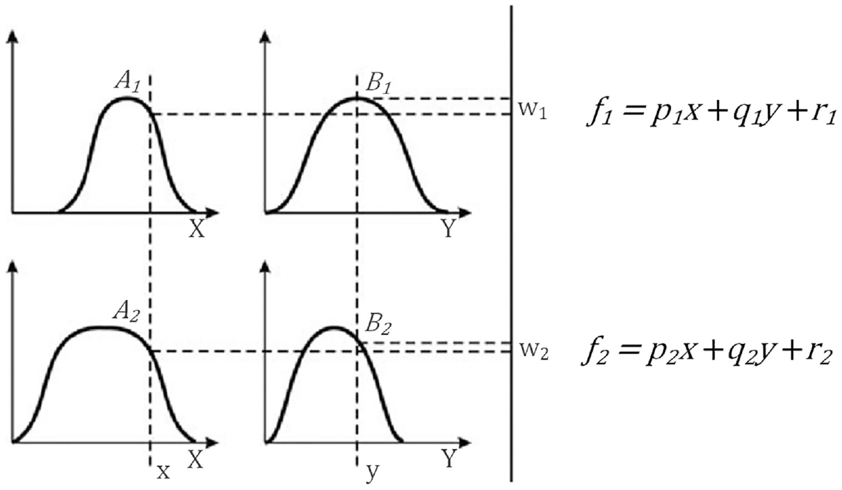
The ANFIS predicts future data on the basis of past samples, using input-output data and fuzzy rules. The If-Then rule 40 is the most often used fuzzy rule in the TS fuzzy model, as seen in Figure 3. Consider, for instance, a model with two If-then fuzzy rules 41 :
Rule1: if x is A1 and y is B1; then
Rule2: if x is A2 and y is B2; then
Takagi and Sugeno model.
Here, the inputs are x and y; the fuzzy sets are Ai and Bi; the output is ƒi; and the fixed design coefficients during training are pi, qi, and ri. using training data, the ANFIS topology optimizes the coefficients of the fuzzy inference system. The disparity between anticipated and measured data is optimized until it is close to zero. 42
The fuzzy membership grade displays the first layer outputs. The ith node’s function is constructed using the bell membership expression given by equation (16).
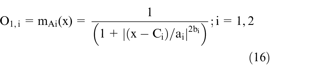
The membership function’s coefficients are presented by ai, bi, and ci, with Ai representing the linguistic label. The input of node i is denoted by x. To fuzzify the inputs, the AND function is used in the second layer. Equation (17) provides the desired result:

Each Layer 3 node labeled N serves as a fixed node to normalize the shooting forces of the previous layer. The third layer accomplishes the normalizing function using equation (18) to construct its output.
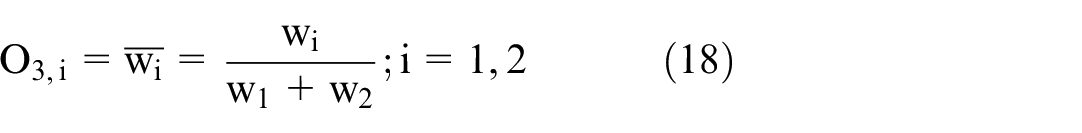
The output of every node in the fourth layer is the sum of the normalized firing strengths and the first-order polynomial, as described by the following equation.

The parameters pi, qi, and ri are obtained, where wi represents the third layer output. The model’s output is displayed in the fifth layer, which can be illustrated by equation (20).

Robust TSMC
As a perspective to enhance control performance, a novel SMC approach called Robust Terminal Sliding Mode (RTSMC) has been recently developed. This innovative approach offers superior characteristics compared to the conventional SMC of a DC-DC converter, such as faster convergence within a finite time. In applications demanding high-precision processing, its usefulness shines, and it speeds up convergence rates in uncertain nonlinear systems of order two or higher, especially close to the chosen equilibrium point.43,44 The RTSMC is employed to achieve maximum power tracking by ensuring a close alignment between the Vpv and the Vpvref. The SMC approach exhibits extraordinary stability and resilience even in the face of parameter uncertainties, including those linked to input and load changes frequently found in PV systems. Furthermore, the construction of sliding mode controllers is easier than other types of nonlinear controllers. The initial step in the design process is to define the error-tracking parameters (voltage and current), as follows:


The reference current is


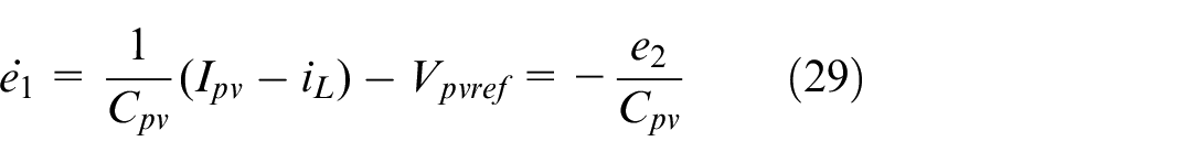
So, using the two equations (9) and (11), the error dynamics are described as follows:
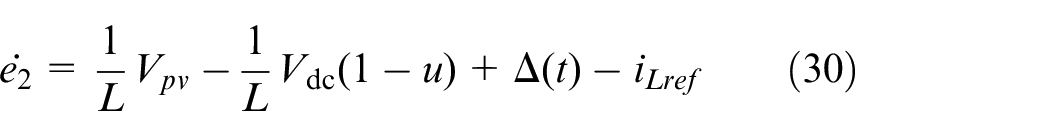
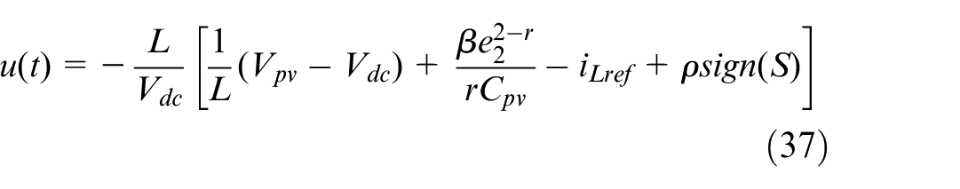
The control objective is to direct the system trajectory to approach the sliding surface within a limited timeframe in order to provide a pulse width modulation (PWM) control at time (t).
The terminal sliding mode controller defines the function S(t) as follows:
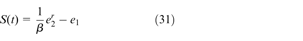
where β is a positive constant, r is the ratio p/q of two positive odd integers satisfying 1 < r < 2 and 0 < q < p < 2q. These conditions ensure the regulated system’s reliability and sturdiness.
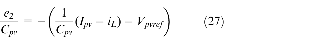
S(t) =0 indicates the sliding condition that is satisfied when e2 is represented as:

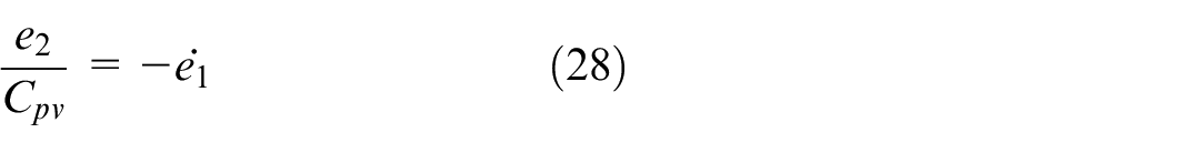
And (29) becomes,
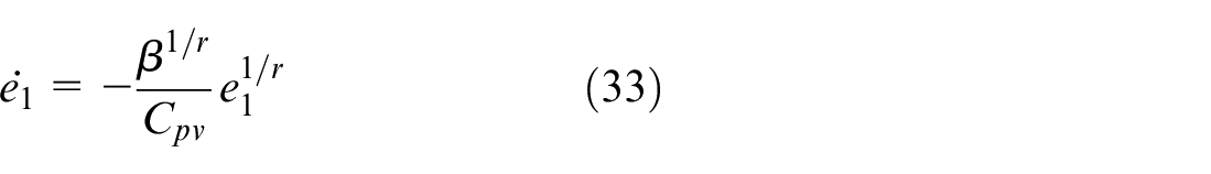
This leads to stable convergence of both e1 and e2 to zero (
Integrating equation (23) yields equation (34)

which can be rearranged as (35)

Finally, the convergence of the error dynamic (33) to zero in finite time is given by equation (36).
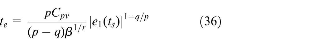
Therefore, the errors (e1, e2) will eventually converge to zero when (S(t) = 0) the system is compelled onto the sliding surface and achieve MPPT. On the basis of these results, we can state the following theorem: for
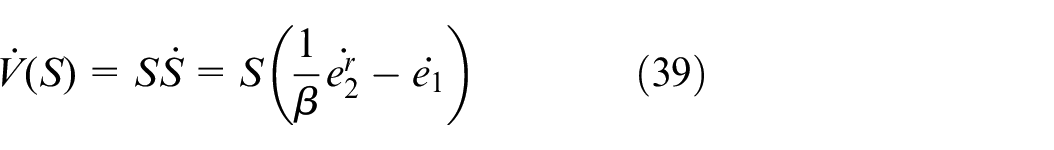
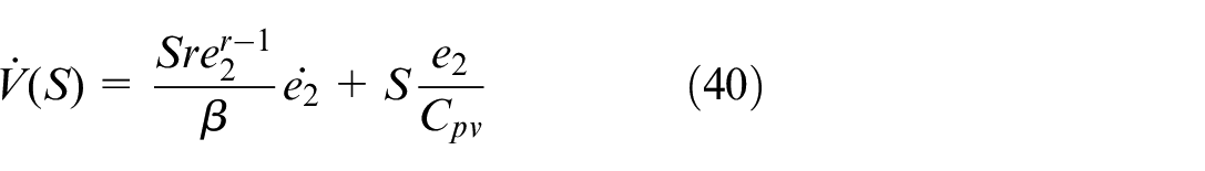
Take the Lyapunov function as evidence.

By calculating the temporal derivative of V(S) through the path defined by equations (29) and (30) using the control rule (37), we obtain:
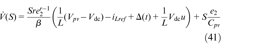
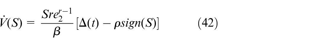
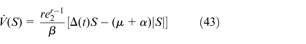
For all e2, the criteria given by (44) leads to (45)

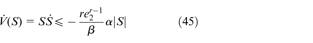
As a result, we can conclude that the reachability condition
Battery charging control
In order to control the power flow into and out of the battery, a BDC is employed, as shown in Figure 4. A voltage PI regulator is used to adjust the Vdc to a reference value equal to 670 V. Additionally, a PI controller is used to regulate the battery charging and discharging current, and the resulting fixed duty cycle is used to generate the appropriate PWM signals for the BDC.
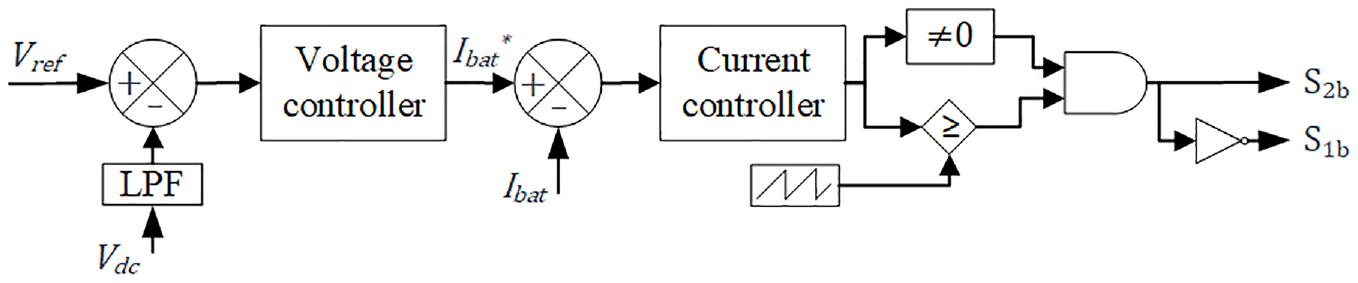
Bidirectional DC-DC converter for power flow control.
Field oriented control of IMD
In this work, the speed control of IMD is achieved using a field-oriented control technique based on SVPWM. This approach offers a distinct advantage over the traditional SPWM technique, utilizing up to 15% more Vdc, as explained in-depth in reference. 45
Simulation results
The performance of the PV/battery/diesel hybrid system has been simulated under MATLAB/Simulink environment. This system comprises a 5 kW PV array powering a 4 kW induction motor with a rated speed of 1430 tr/min and a motor torque of 30 Nm. To evaluate the system’s performance under various operating conditions, multiple simulated scenarios have been presented and analyzed in this section. This analysis provides a comprehensive assessment of the hybrid system’s effectiveness.
Performance during system start-up and steady-state
Figure 5(a) illustrates the simulated system performance, which is initiated with an irradiance of 853 W/m2. MPPT control enables the Vpv to reach its maximum power point voltage (Vmpp) of 554 V, while keeping the steady-state Vdc at 670 V as shown in Figure 5(b), the battery current (Ibat) remains nearly zero as the power required to drive the induction motor at its rated speed is solely supplied by the PV array. The state of charge (SOC) is kept at approximately 50% and the battery voltage (Vbat) is controlled to its designated level. The IMD’s effectiveness at the start-up, depicted in Figure 5(c), demonstrates stability without any oscillations in the steady state.
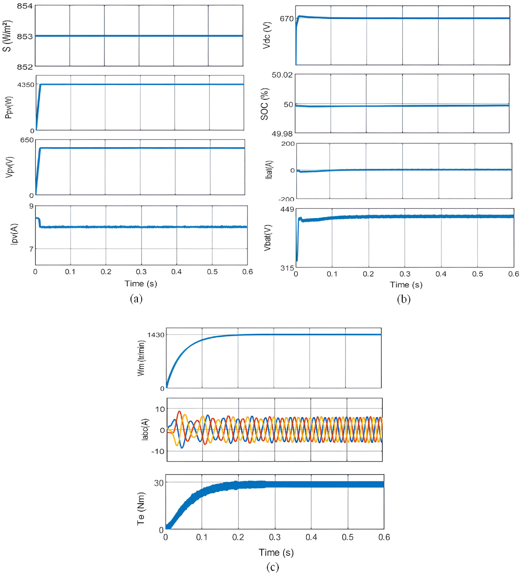
System response of hybrid PV/battery/Diesel system during starting at rated condition: (a) PV parameters, (b) battery parameters, and (c) motor parameters.
System response to variable solar insolation and battery management
The effectiveness of a PV-diesel-battery hybrid system hinges on its ability to adapt to fluctuating solar irradiance. This section delves into the system’s performance under varying solar conditions, specifically focusing on how the proposed ANFIS-RTSMC MPPT method interacts with the battery storage to guarantee continuous and stable operation. We will analyze scenarios involving both battery charging and discharging, highlighting the interplay between efficient power extraction and battery management.
Battery charging
We begin by examining the system’s response to increasing solar irradiance. As depicted in Figure 6(a), the rise in irradiance leads to the establishment of a new operational MPP, resulting in a higher MPP voltage and current. This translates to a significant increase in power generated by the PV array. However, the Vdc remains constant at 670 V, as shown in Figure 6(b). This stability is achieved through the crucial role played by the battery storage system. During periods of high irradiance, the MPPT method efficiently extracts maximum power from the PV array. This surplus power not only fulfills the motor’s operational needs but also contributes to charging the battery. This is evident in Figure 6(b) by the negative value of Ibat and the rising of both SOC and Vbat. The negative Ibat signifies a current flow into the battery, indicating the charging process. The control system effectively manages the bidirectional DC-DC converter to transfer this excess power for battery storage, ensuring its readiness for periods with lower solar radiation. Furthermore, Figure 6(c) demonstrates the system’s stability with minimal transients in the IMD response despite the sudden change in solar irradiance. The motor maintains its rated speed of 1430 tr/min and torque of 30 Nm, showcasing the effectiveness of the combined MPPT and battery management strategy.
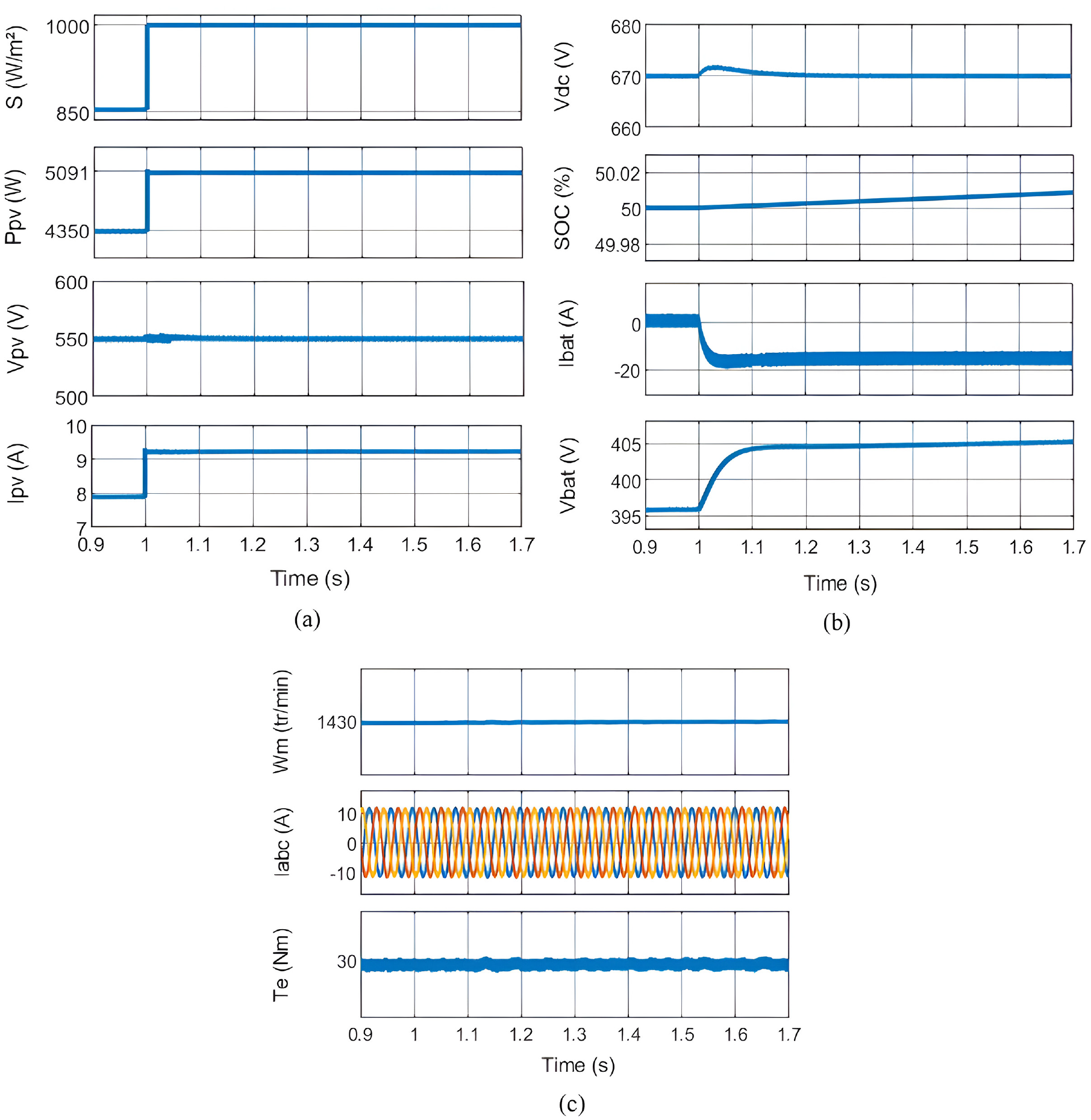
System performance parameters during irradiance increasing from 850 to 1000 W/m2: (a) PV parameters, (b) battery parameters, and (c) motor parameters.
Battery discharging
The system’s response to decreasing solar irradiance is analyzed next. As illustrated in Figure 7(a), a drop in irradiance leads to a decrease in power generated by the PV array. However, the Vdc remains constant at 670 V (Figure 7(b)), ensuring uninterrupted operation of the motor pump. To maintain this voltage level despite the decline in PV power, the battery storage system comes into play. The control system draws more power from the battery, as indicated by the negative value of Ibat in Figure 7(b). This negative Ibat signifies a current flow out of the battery, representing the discharging process. Consequently, the SOC of the battery steadily decreases. It’s important to note that as the irradiance falls to a critical level (around 300 W/m2 in this scenario), the battery starts contributing a significant portion of the power required by the motor to compensate for the diminished PV output. This ensures the motor pump’s continued operation at its rated speed and torque, as shown in Figure 7(c).
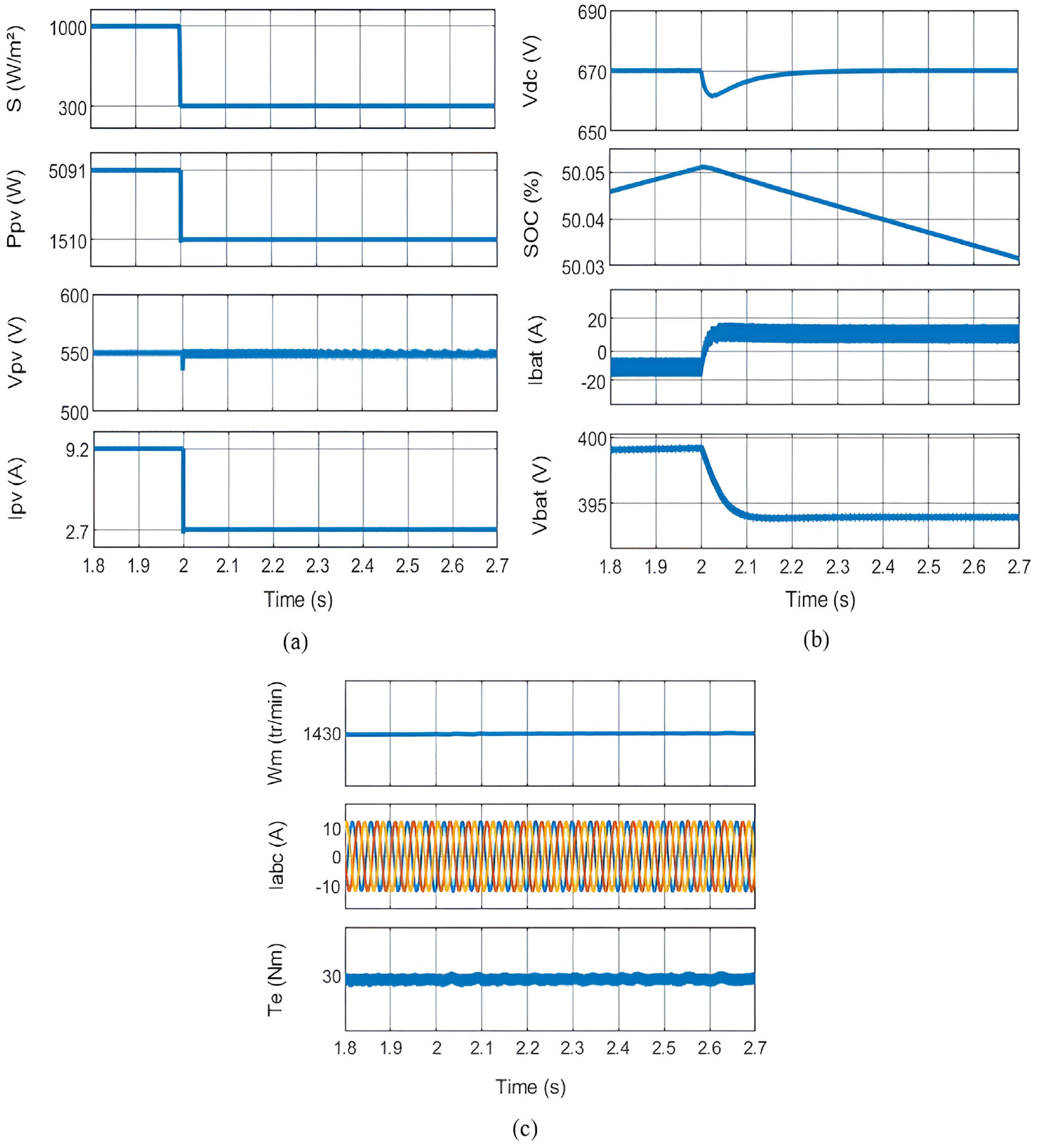
System performance parameters during irradiance decreasing from 1000 to 300 W/m2: (a) PV parameters, (b) battery parameters, and (c) motor parameters.
Intervention of the diesel generator for backup power generation
In the two-stage hybrid motor pump system, consisting of a PV array, battery storage, and a diesel generator, the diesel generator plays a crucial role in ensuring an uninterrupted power supply when the PV power is insufficient or unavailable. Its intervention becomes necessary when the battery’s SOC drops below the critical threshold of 20%, serving as a reliable backup power source.
Figure 8(a) visually demonstrates this situation by illustrating the decrease in solar irradiation, which subsequently leads to a decline in PV power output until it eventually reaches zero. Throughout this period, the control system diligently keeps a constant 670 V for the Vdc. Meanwhile, Figure 8(b) provides an overview of the battery’s state during this period, highlighting a significant discharge as it compensates for the absence of PV power. However, it is important to note that the battery’s ability to provide power is limited, and it continues to discharge until it reaches its minimum limit. To counter the energy deficit caused by the absence of PV power and the low battery SOC, the control system automatically initiates the diesel generator. This intervention allows the diesel generator to power the motor pump, ensuring its continuous operation, while simultaneously charging the batteries to restore their SOC. The transitional phase, commonly known as “Diesel Generator-Powered Operation with Battery Charging,” is depicted in Figure 8(c). Notably, regardless of the solar irradiance value, the system diligently maintains the motor pump’s rated speed, guaranteeing optimal performance under diverse operating conditions.
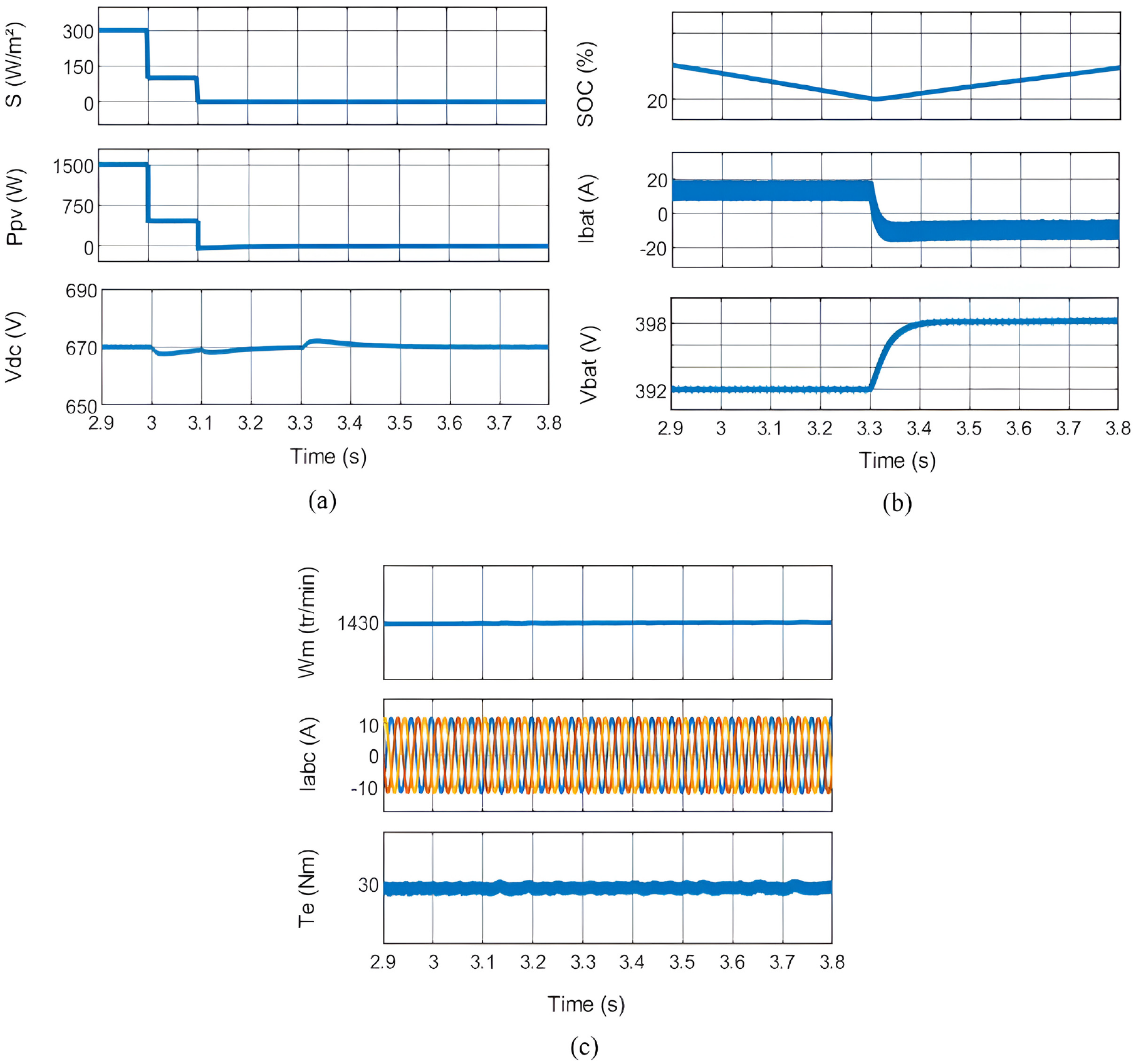
System performance parameters during irradiance decreasing from 300 to 0 W/m2: (a) PV parameters, (b) battery parameters, and (c) motor parameters.
MPPT performance analysis
Solar irradiation test
The ANFIS-RTSMC MPPT technique’s performance is assessed against four different MPPT algorithms in the presence of varying solar insolation using the Ropp test, which was first suggested by previous work. 46 The Ropp test involves subjecting the MPPT algorithm to varying solar irradiance conditions represented in Figure 9. This evaluation aims to determine the algorithm’s capability to handle both gradual and sudden changes in irradiance levels, as well as its response under the SteadyState condition. The test starts at an irradiance of 200 W/m2, gradually increasing to 1000 W/m2. Subsequently, four-step changes in irradiance are introduced: (1000–200), (200–600), (600–200), and (200–1000) W/m2. At last, the irradiance progressively drops from 1000 to 200 W/m2.
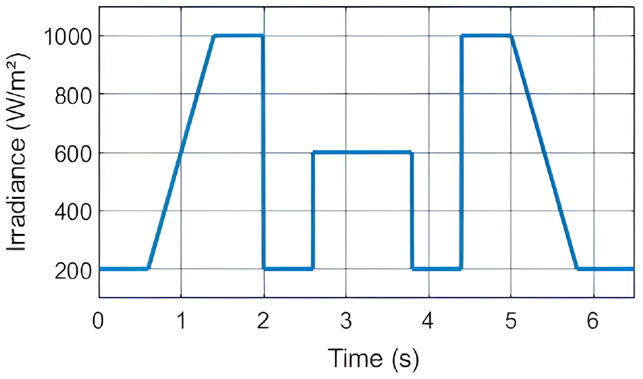
Ropp test irradiance profile.
Ambient temperature test
To assess thermal performance, we simulated a rapid temperature rise, 25°C–35°C and then to 45°C over 3 s, as depicted in Figure 10, under constant 1000 W/m2 irradiance. This test compares the proposed method’s robustness against P&O and NN-RTSMC algorithms.
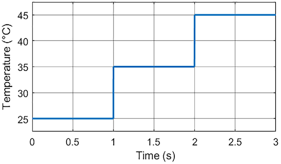
Temperature profile.
Discussion
The tracking performances of various MPPT techniques can be assessed by analyzing the output power profile depicted in Figure 11 with its enlarged parts.
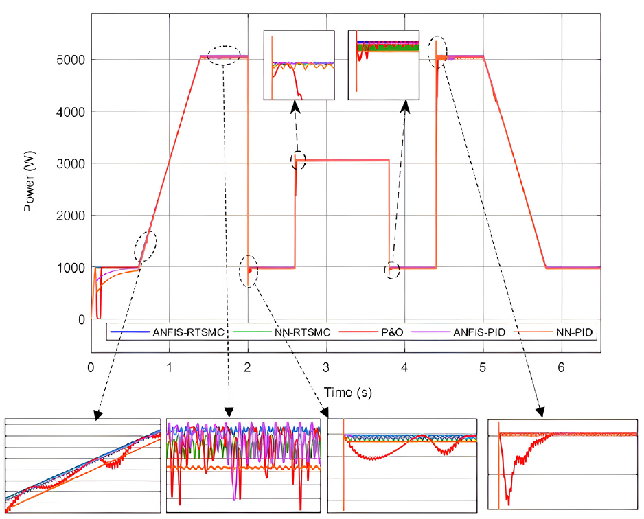
Comparison of the tracking performance of the different MPPT.
In this scenario, five MPPT algorithms were evaluated: the P&O algorithm, the NN-PID, the ANFIS-PID, the NN-RTSMC, and the ANFIS-RTSMC. The ANFIS-RTSMC MPPT exhibited exceptional accuracy in tracking the irradiance profile, demonstrating minimal oscillation and the shortest time to reach the MPP. With an almost invisible perturbation size, it consistently maintained its tracking point. The NN-RTSMC MPPT, which shares similarities with the ANFIS-RTSMC MPPT, showcased effective tracking performance, with a minor limitation observed during rapid ramp-up and down of the irradiance. However, it quickly regained its tracking point. Next, we assess the hybridization of ANFIS and NN with PID control. The NN-PID method reduces oscillations during ramp-up or down and steady-state, despite longer tracking times at start-up. Although, it encounters challenges in precise reference tracking, resulting in temporary losses during rapid irradiance changes. Similarly, the ANFIS-PID hybrid approach exhibits extended start-up tracking times but achieves better performance with smaller oscillations during ramp-up or down periods, though some oscillations are observed at high irradiance levels. Nevertheless, the P&O algorithm exhibited longer tracking time, especially during start-up, and after the loss of tracking direction during rapid irradiance changes. Furthermore, it displayed notable oscillations at high irradiance levels, and a tendency to lose tracking direction with large oscillations during gradual irradiance changes. In conclusion, among the five evaluated MPPT algorithms, the ANFIS-RTSMC MPPT stands out as the superior technique. With exceptional accuracy in tracking the irradiance profile, minimal oscillation, and the shortest time to reach the MPP, it outperforms the other methods. Its ability to maintain its tracking point with an almost invisible perturbation size showcases its robust and reliable performance, making it the best choice for efficient and precise MPPT.
Figure 12 focuses on the MPPT tracking performance of the PV generator’s output powers for the P&O, NN-RTSMC, and ANFIS-RTSMC methods under varying temperature conditions. This graph demonstrates that PV reference voltage tracking is accurate for all three algorithms, successfully maintaining the PV system’s MPP for the majority of the time. However, a clear distinction emerges in terms of response speed and stability. Consistent with the solar irradiation test, the P&O and NN-RTSMC algorithms exhibit a slower convergence with more oscillations. In contrast, the ANFIS-RTSMC algorithm presents superior performance, demonstrating its robustness in transient temperature changes. Notably, it maintains minimal oscillations and avoids deviations from the MPP, highlighting its effectiveness under varying thermal conditions.
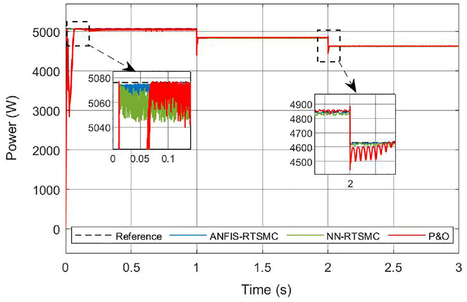
PV Power generation under temperature test.
The MPPT efficiency of various procedures is used to evaluate their effectiveness. The following equation is used to calculate instantaneous MPPT efficiency:

The provided expression denotes the average efficiency of the MPPT

Within equations (46) and (47), the variable P MPP* represents the utmost potential power attainable, which serves as the algorithm’s objective. It is determined through the employment of the PV model. Conversely, PMPP stands for the real power obtained through the MPPT algorithm. Its value relies on the algorithm’s ability to closely match the instantaneous irradiance.
Examining the MPPT efficiency (ηMPPT) of the P&O algorithm, the NN-RTSMC and the ANFIS-RTSMC, as illustrated in Figure 13(a)–(c) and computed by equation (46), reveals interesting insights. The P&O algorithm exhibits efficiency oscillation ranging from 95% to 98%. Nevertheless, the efficiency plummets to as low as 75% in cases of tracking direction loss. In the case of the NN-RTSMC MPPT, the efficiency remains consistently around 99% for most of the time but experiences a slight decline to the 90% range during tracking divergence. In contrast, the proposed ANFIS-RTSMC MPPT demonstrates minimal steady-state oscillation. It closely follows the power locus during changes in irradiance, distinguishing it from other MPPT techniques. Throughout the whole Ropp profile cycle, the calculated average MPPT efficiency, ηMPPT (ave), the P&O algorithm, NN-RTSMC MPPT, and ANFIS-RTSMC MPPT are determined to be 95.6%, 98.84%, and 99.4%, respectively. These results highlight the superior performance of the proposed ANFIS-RTSMC MPPT in achieving high efficiency and accurate power tracking throughout the cycle.
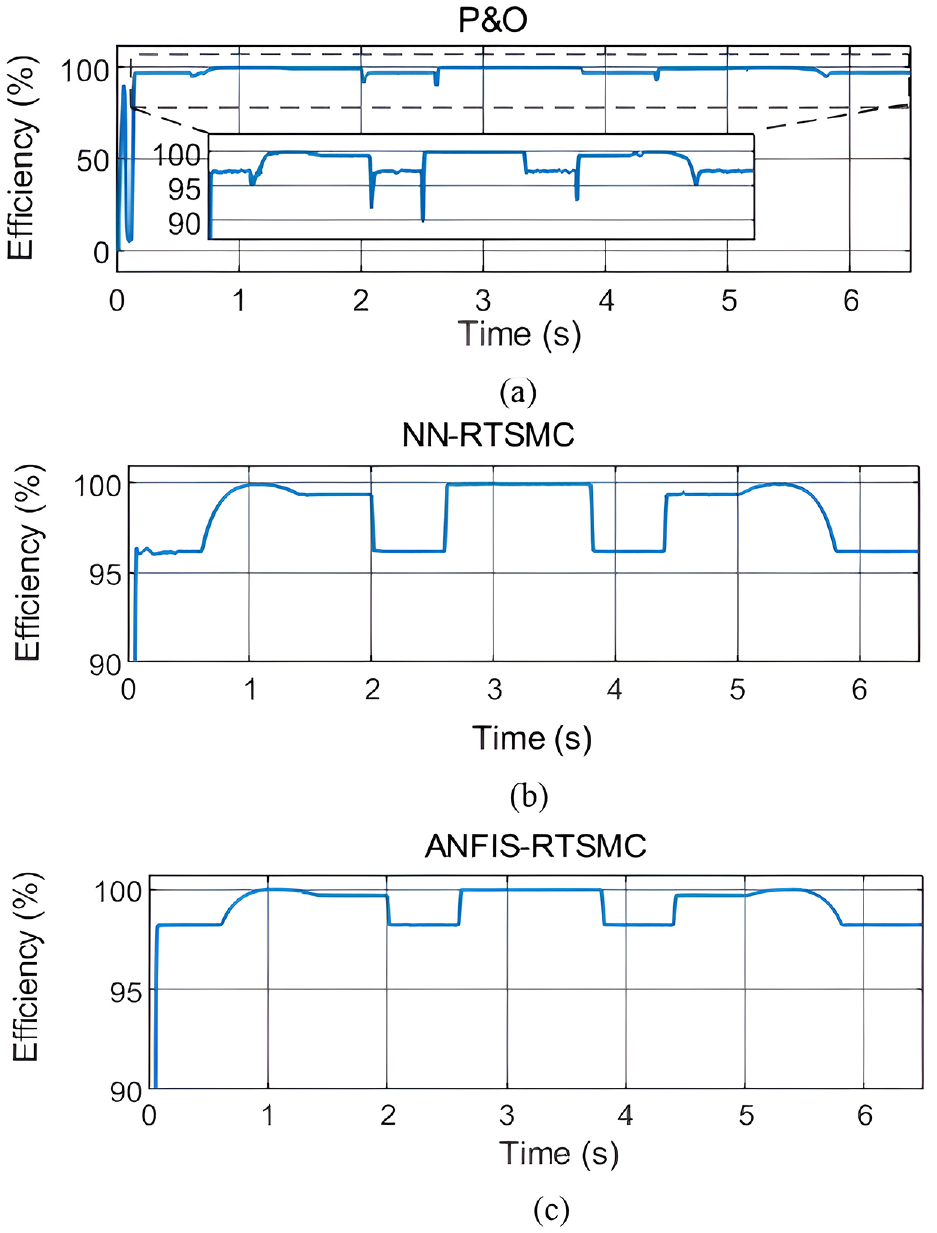
Efficiency of (a) P&O, (b) NN-RTSMC, and (c) ANFIS-RTSMC.
To further quantify the accuracy and reliability of the MPPT algorithms, we incorporate the Root Mean Squared Error (RMSE) as a metric to evaluate the deviation between the actual power output and the theoretical maximum power. The RMSE is calculated using the following equation:

Here, N represents the total number of data points. A lower RMSE value indicates better tracking performance and less uncertainty in the MPPT algorithm’s ability to follow the MPP.
To further evaluate the tracking accuracy of the proposed ANFIS-RTSMC controller, we conducted an RMSE analysis. The RMSE provides insights into the average difference between the estimated power values generated by the controller and the actual power output of the PV system. A lower RMSE signifies better agreement between the estimated and actual power, indicating a more accurate and efficient tracking performance by the controller. To further assess the tracking accuracy of our ANFIS-RTSMC controller, we conducted an RMSE analysis alongside established algorithms detailed in Table 2. 47
RMSE analysis.

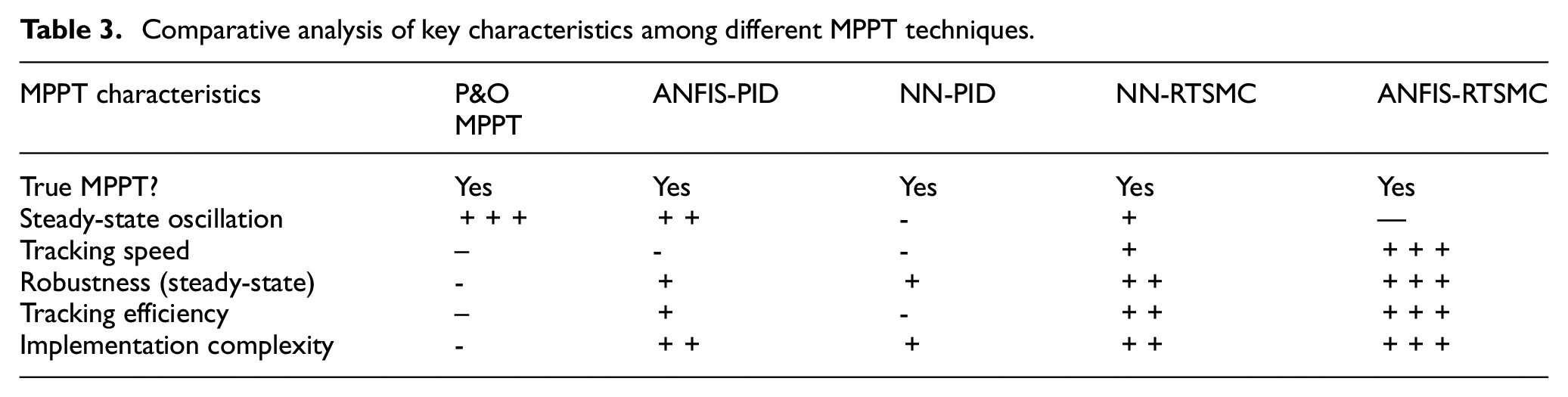
The suggested MPPT approach is thoroughly compared with several existing methodologies, along with the MPPT tracking performance, as summarized in Table 3. The table emphasizes several advantageous features of the ANFIS-RTSMC MPPT tracking method when compared to other approaches. These advantages include its exceptional capability to accurately track the true MPP, robust and steady-state performance free from oscillations, rapid-tracking speed, and high efficiency in tracking.
Comparative analysis of key characteristics among different MPPT techniques.
Conclusion and future works
This study presents an innovative hybrid approach that combines the Robust Terminal Sliding Mode Control (RTSMC) with the Adaptive Neural Fuzzy Inference System (ANFIS) to achieve MPPT in a PV-Diesel-Battery Hybrid water pumping system featuring an induction motor drive. Our novel two-stage power conversion structure, consisting of a boost DC-DC converter and a three-phase VSI, has been meticulously modeled and simulated using MATLAB/Simulink. This unique combination of ANFIS and RTSMC provides unparalleled stability, rapid response, and minimal oscillations, significantly enhancing the system’s efficiency and reliability under variable solar conditions. Comparative evaluations against conventional methods, such as P&O, NN-PID, ANFIS-PID, and NN-RTSMC, demonstrate the superior accuracy and performance of our proposed method. This innovative approach ensures a stable and efficient water pumping system, addressing the challenges of variable solar power availability. Future work will focus on practical validation of the simulation outcomes using a dedicated test bench with a detailed cost analysis and exploring grid integration capabilities, further solidifying our proposed solution’s originality and practical applicability.
Footnotes
Appendix
Declaration of conflicting interests
The author(s) declared no potential conflicts of interest with respect to the research, authorship, and/or publication of this article.
Funding
The author(s) received no financial support for the research, authorship, and/or publication of this article.
Ethical approval
Ethical approval is not applicable to this study as it did not involve human or animal subjects.
Data availability statement
The data underlying this article will be shared on reasonable request to the corresponding author.