
Abstract
The distinct characteristics of photovoltaic (PV) generators related to power and current present a complex problem in terms of optimizing their power output. To tackle this, a Maximum Power Point Tracking (MPPT) interface is required to extract the full power and increase the efficiency. The purpose of this research is to propose an innovative method that merges the Adaptive Neuro-Fuzzy Inference System (ANFIS) and the Fast Terminal Synergetic Controller (FTSC) to refine the tracking of the optimal power point and to bolster the PV system’s stability in the face of unpredictable scenarios. Simulations conducted using MATLAB/Simulink demonstrate that the ANFIS-FTSC achieves an impressive efficiency of 99.89%, and exhibits fast, robust, and accurate responses compared to other algorithms like FTSC and conventional P&O.
Introduction
In light of the current trajectory of energy consumption and the finite nature of fossil and fissile energy reserves, coal, oil, gas, and uranium projects indicate a limited timeframe, extending no more than a few decades or, optimistically, slightly over a century. This pressing concern gains urgency as global energy demands continue their upward trend, prompting a widespread quest for alternative and sustainable energy sources. Renewable energy has taken center stage as a fundamental solution to the impending depletion of conventional energy reserves. A discernible shift away from fossil fuels is evident, marked by a reduction from 86% in 1973 to 81% in 2008, signifying a collective global effort toward embracing more sustainable energy alternatives. 1 Among these alternatives, solar PV systems stand out, particularly in applications, such as domestic and water distribution, where their practicality is underscored by notable technological advancements. As of 2017, the cumulative installed capacity of PV systems reached a significant milestone of 402 GWp, attesting to substantial investments driven by the simplicity of installation and cost-effectiveness of maintenance. 2 The increasing competitiveness of PV systems is attributed to advancements in materials and a decline in overall system costs, positioning them favorably among various renewable energy sources. However, persistent challenges arise despite these challenges. Inherent volatility, intermittency, and susceptibility to load impedances contribute to the overall inefficiency of PV systems. This article aims to delve into the realm of MPPT techniques, exploring innovative strategies designed to address the challenges posed by fluctuations and intermittency. The aim is to optimize the efficiency of PV systems, contributing to the dynamic landscape of renewable energy in a manner that is both sustainable and economically viable.
In this context, researchers have committed their time to creating effective MPPT techniques capable of swiftly and accurately determining the optimal operating point for solar power systems. The objective is to minimize power losses and ensure effective operation under varying and uncertain conditions. 3 The development of MPPT techniques has been motivated by the necessity to improve accuracy, efficiency, and the incorporation of various factors, such as ease of use, convergence speed, specific implementation, required sensors, cost efficiency, and adaptability.4,5 A wide range of techniques has been proposed over the years, encompassing conventional MPPT methods, such as Constant Voltage (CV), 6 Fractional Short Circuit Current (FSCC),7,8 Fractional Open Circuit Voltage (FOCV), 9 Look-up Table (LUT), 10 Perturb and Observe (P&O),11,12 and Incremental Conductance (INC),13–15 offer a simple and straightforward approach. While widely used, these methods can suffer from limitations such as slow convergence and oscillations around the MPP, especially under rapidly changing environmental conditions. To overcome these limitations and achieve faster and more accurate MPPT, research has shifted toward intelligent control techniques. Model Predictive Control (MPC), 16 Fuzzy Logic Control (FLC),17–19 Radial Basis Function Neural Network (RBFNN), 20 and Artificial Neural Networks (ANN),21,22 are prominent examples. FLC offers faster tracking speeds and reduced fluctuations compared to conventional methods.23,24 However, it can be sensitive to irradiation and temperature changes, requiring precise PV system knowledge to prevent inaccurate fuzzy rules.25,26 ANNs demonstrate improved stability around the MPP, but training time and the “black-box” nature of the model present challenges.27,28 The integration of ANN and FLC yields a more robust and intelligent method: the ANFIS.29,30 ANFIS-MPPT offers fast responses and minimal oscillations due to faster adaptation under varying weather conditions. However, obtaining accurate data for training and fine-tuning the ANFIS controller can be challenging.31,32 Additionally, the field has seen the exploration of algorithms inspired by natural phenomena, such as Ant Colony Optimization (ACO), 33 and Particle Swarm Optimization (PSO).34,35 The Butterfly Optimization Algorithm (BOA) 36 is another emerging technique that utilizes principles inspired by butterfly foraging behavior to achieve efficient MPPT. The intrinsic nonlinear characteristics of PV modules and power electronic converters make nonlinear controllers an ideal choice for achieving MPPT in PV systems. Two widely adopted strategies for robust tracking capabilities amid uncertainties and parameter variations are Sliding Mode Control (SMC), 37 and backstepping (BS). 38 Additionally, the synergetic approach, such as Fractional Nonlinear Synergetic Control (FNSC), 39 has emerged as a potent control strategy, exhibiting noteworthy theoretical and experimental success in diverse applications, including DC-DC converters 40 and PV systems for MPPT under varying environmental conditions. 41 While purely intelligent techniques like ANFIS and ANN offer advantages, they can face challenges due to system nonlinearities. To address this, research has explored hybrid approaches that combine the strengths of intelligent techniques with established nonlinear control theories. These hybrid approaches, such as ANFIS-BS 42 and ANFIS-TRSMC, 43 offer the potential to achieve superior performance.
Inspired by the considerations mentioned earlier, this article introduces an innovative methodology that seamlessly integrates the strengths of nonlinear controllers with artificial intelligence (AI). This novel approach is particularly adept at handling dynamic scenarios with fluctuating temperature and irradiance, where traditional methods often struggle. Traditional nonlinear controllers, while effective, can see their effectiveness wane under environmental fluctuations due to a lack of adaptability. Our proposed solution elevates MPPT precision and robustness by integrating AI. By incorporating real-time environmental data, the system can develop adaptive control tactics that dynamically adjust to changing conditions. This dynamic responsiveness ensures reliable performance despite external factors and the inherent unpredictability of weather patterns. The core innovation lies in the ingenious combination of two powerful techniques: FTSC and ANFIS. FTSC offers rapid convergence and skillfully manages system nonlinearities, ensuring stable operation. 40 ANFIS, an AI technique, provides superior response speed and accuracy compared to traditional fuzzy logic controllers, leading to more precise MPPT. This hybrid approach offers several advantages. It surpasses the individual capabilities of FTSC and ANFIS by achieving faster convergence, improved accuracy, and robust performance under varying environmental conditions. The AI component allows the system to learn and adapt its control strategy based on real-time data, ensuring optimal performance despite fluctuations. Additionally, the approach offers greater resilience to environmental variations and provides flexibility for future advancements by allowing for the integration of additional AI techniques. The proposed dual-stage control strategy leverages the strengths of both FTSC and ANFIS, making it a practical and readily implementable solution. The ANFIS model is first refined to accurately track the reference optimal power voltage. This information is then effectively incorporated into a two-stage process.44,45 In the first stage, the ANFIS model analyzes real-time environmental data to determine the MPP reference voltage (Vpvref). In the second stage, the traditional nonlinear controller is replaced by the FTSC, which continuously formulates the control signal for the boost converter by evaluating the discrepancy between the PV array’s output power and the MPP to maximize power generation. Overall, this dual-stage MPPT control strategy offers a robust and effective solution for enhancing PV array power generation. The controller exhibits prompt and precise adaptation to environmental fluctuations, ensuring optimal performance under dynamic conditions.
The organization of this paper is as below: the MPPT PV-boost converter system’s block diagram is shown in the next section, providing comprehensive models for each constituent component. The third section introduces the proposed algorithm, ANFIS-FTSC, outlining its methodology. Transitioning to the fourth section, we demonstrate the efficient and robust performance of the ANFIS-FTSC MPPT. This demonstration includes a comparative analysis against the P&O and FTSC algorithms, serving as a critical evaluation of our contributions. Lastly, the fifth section encompasses the conclusion and discussions on future endeavors.
Photovoltaic system modeling
Several physical components must be integrated to produce electrical energy while modeling a PV system. Our suggested solution employs a thorough block diagram, as shown in Figure 1. A PV panel serves as the main current source in this self-contained model. The MPPT technique is employed in integrating a DC-DC boost converter connected to the PV generator. By applying this method, the system’s load and the PV panel’s output voltage are optimally adapted, resulting in maximum energy efficiency.
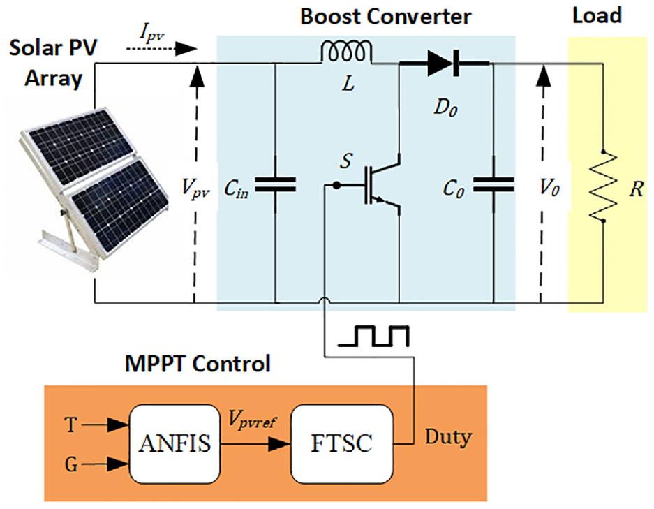
System diagram for the PV system.
Modeling of PV module
Analyzing the behavior of a PV module entails a detailed examination of its solar cells, with a primary focus on the PN junction diode. These cells harness energy from sunlight and convert it into electricity, as elucidated by Kalaiarasi et al. 29 Various models, Rs-Rp models, double-diode, and single-diode, are available for representing PV cell designs. For simplicity, we adopted the model single-diode presented in Figure 2, as proposed by Shaw. 46
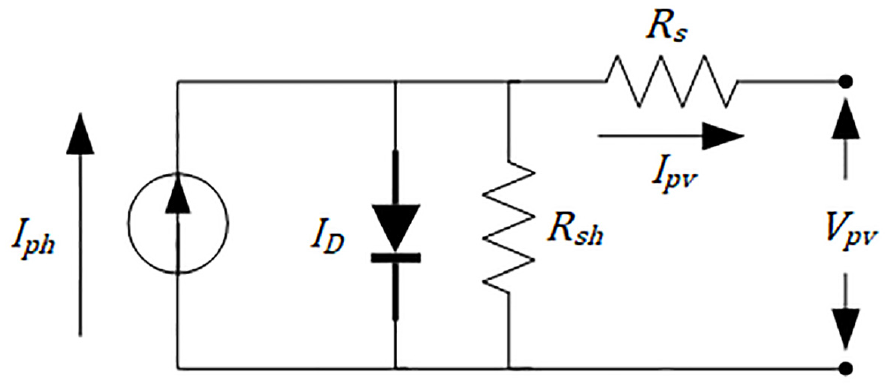
Solar cell.
The efficiency of a PV panel is significantly influenced by the series resistance, which impacts key properties such as the current and voltage within the PV system. On the contrary, shunt resistors have a negligible effect on system functionality and effectiveness, leading to the common practice of neglecting this resistance, which leads to the creation of an open circuit. 3 The mathematical expression for the generated current Ipv of the PV cell is as follows:
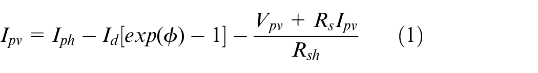
With


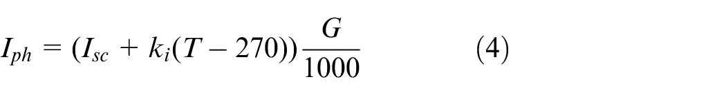

In these equations, Idr signifies the dark saturation current reference, I d is the dark saturation current, Iph represents the photocurrent and Isc is the short-circuit current. n s stands for the number of series cells in the PV panel; Rsh represents the shunt resistance and R s represents the series resistance. Additionally, V t represents the thermal voltage, where e, E g , k i , and k b stand for the electron charge, photon energy, Boltzmann constant, respectively and short-circuit coefficient.
DC/DC boost converter
A boost converter functions as a power electronic device crafted to transform the input DC voltage into a higher-level output voltage. Consisting of an inductor (L), diode (D), and switch (S) to protect the switch during a current return, as illustrated in Figure 1, this device plays a pivotal role in the power conversion process.
In the context of achieving MPPT for the PV system, control over the boost converter’s duty cycle (D) is essential, particularly when addressing diverse configurations of PV systems set under fluctuating irradiation levels and ambient temperatures. 47 An input capacitor was used to handle high-frequency harmonic components on the PV panel’s input side. As per Rezk and Elta 48 the formula for calculating the duty cycle for the MPP is:

In this context, Pmpp represents the power of the panel at the MPP, Rload is the equivalent resistance of the converter, Vmpp is the voltage of the PV panel at the MPP, Dmpp indicates the desired duty cycle of the boost converter at the MPP. Utilizing the average method and considering the characteristics of the PV array, we derive the dynamic equations of the boost converter, as depicted below:
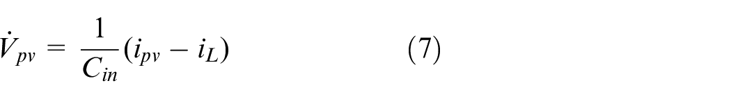
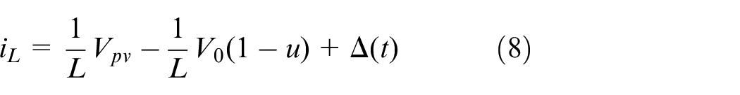

Here iL signifies the current flowing through the inductance L, u [0; 1] signifies the PWM duty cycle ranging from 0 to 1, V0 represents the output voltage, R denotes the resistive load, and Δ(t) characterizes uncertain elements arising from system uncertainties, variations in Vpv caused by load disturbances and measurement anomalies. Moreover, Δ(t) complies with the provided criteria:

MPPT design
In this section, we present the proposed MPPT design, which is based on a hybrid approach that combines ANFIS and TSMC, and its flow chart with the signal flow is presented in Figure 3. The MPPT design is divided into two main parts: Reference voltage generation using the ANFIS Algorithm. FTSC, which utilizes the generated Vpvref as input to create the FTSC signal (dFTSC), ensures finite-time convergence for achieving the MPP.
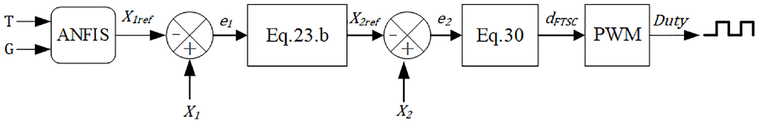
The proposed closed-loop system control.
Reference voltage generation using the ANFIS algorithm
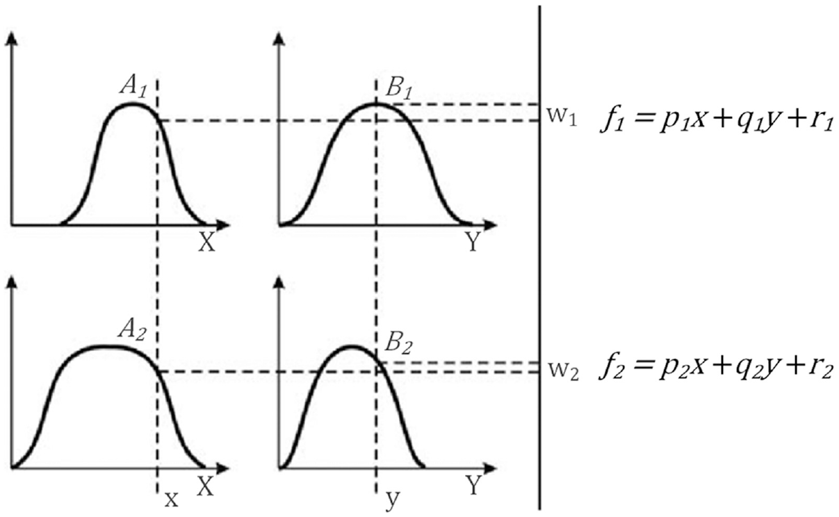
The Neuro-Fuzzy Algorithm combines the benefits of ANN and the model of Takagi and Sugeno (TS). This approach provides an excellent representation of knowledge through fuzzy systems and enhances system performance due to the learning capabilities of neural networks. As illustrated in Figure 4, this algorithm comprises five layers: Normalization, Fuzzification, Consequences, Addition, and Rules. 49 Adaptive sections are represented by square nodes, while non-adaptive sections are denoted by circular nodes. Temperature and irradiance are inputs to the neuro-fuzzy network. The Fuzzification layer plays a crucial role in converting crisp input values (temperature and irradiance) into fuzzy membership grades. This layer utilizes Gaussian membership functions, a type of bell-shaped function (though with specific mathematical properties) commonly used in TS models as illustrated in Figure 5. Gaussian membership functions offer several advantages. Firstly, they provide smooth transitions between membership grades (from 0 to 1). This smooth transition property is crucial in this application because abrupt changes would negatively impact the model’s ability to handle variations in temperature and irradiance. Since our model deals with a wide range of environmental conditions, smooth transitions are essential for generating a stable and accurate reference voltage. Additionally, the number of Gaussian membership functions used for each input parameter determines the number of fuzzy sets. In our case, we opted for three Gaussian membership functions for each input variable, resulting in a total of nine fuzzy rules (3 × 3 = 9). These rules generate the Vpvref for peak power using linear equations. 50

Reference voltage generation.
Takagi and Sugeno model.
The ANFIS predicts future data based on past samples, using input-output data and fuzzy rules. The If-Then rule is the most often used fuzzy rule in the TS fuzzy model, 51 as seen in Figure 5. Consider, for instance, a model with two If-then fuzzy rules 52 :
Rule 1: if y is B1 and x is A1; then
Rule 2: if y is B2 and x is A2; then
Here, the inputs are x and y; the fuzzy sets are B i and A i ; the output is ƒ i ; and the fixed design coefficients during training are p i , q i , and r i . using training data, the ANFIS topology optimizes the coefficients of the fuzzy inference system. The disparity between anticipated and measured data is optimized until it is close to zero. 30
The fuzzy membership grade displays the first layer outputs. The ith node’s function is constructed using the bell membership expression given by equation (11).
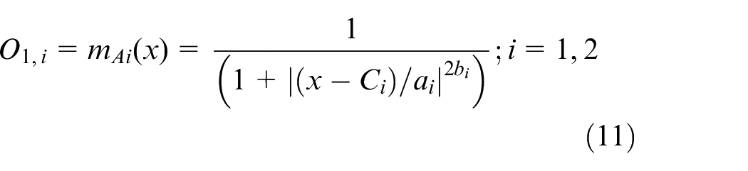
The membership function’s coefficients are presented by a i , b i , and c i , with A i representing the linguistic label. The input of node i is denoted by x. To fuzzify the inputs, the AND function is used in the second layer. Equation (12) provides the desired result:

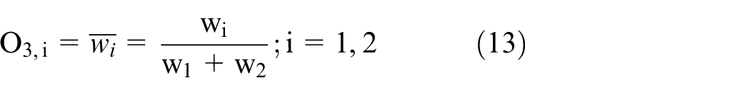
Each Layer 3 node labelled N serves as a fixed node to normalize the shooting forces of the previous layer. The third layer accomplishes the normalizing function using equation (13) to construct its output.
The output of each node in the fourth layer is the sum of the normalized firing strengths and the first-order polynomial, as defined by the following equation.

The parameters q i , r i , and p i are obtained, where w i represents the third layer output. The model’s output is displayed in the fifth layer, which can be illustrated by equation (15).

Our ANFIS model was trained using a combination of historical data and simulated data. Historical data were collected from a real-world PV installation over a period of 12 months, capturing a wide range of environmental conditions, including sunny and cloudy scenarios. Additionally, synthetic data were generated using MATLAB to simulate extreme conditions not frequently encountered in the real-world dataset. The simulation included variations in temperature and irradiance to cover a comprehensive range of operational scenarios, enhancing the robustness of the model.
Basics of synergetic control theory and fast terminal synergetic controller design for PV systems
In this section, we introduce the fundamentals of Synergetic Control Theory (SCT) through a nonlinear differential function governing a controlled system:

Here, the control input vector is d, and x represents the system state vector. Selecting a macro variable (MV) is a step in the Synergetic Control (SC) synthesis process, 53 denoted as Ψ (x, t), guiding the system trajectory toward the attractor Ψ = 0. The dynamic evolution of Ψ is determined by the equation:

The selection of T s affects the system’s convergence speed to the equilibrium point. Upon differentiating the macro variable (MV), we obtain:

Substituting equations (16) and (18) into equation (17), we derive the control law expression:

This leads to the control law expression:

The success of equation (20) depends on the appropriate selection of both the macro variables T s and Ψ to ensure performance, system stability, and robustness.
Moving on to problem formulation, the goal is to derive a control law ensuring desired values for the PV output voltage (x1 = x1ref) and inductance current (x2 = x2ref). The tracking error is defined as:

Where:


The tracking error dynamics are given by:


Introducing new variables:


The equations (23) and (24) can be expressed as:

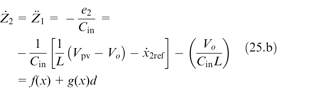
With the problem formulated, the next step is to choose a control law ensuring convergence of both Z1 and Z2 to zero. In the following section, we employ the FTSC theory to derive a continuous control law (dFTSC) ensuring finite-time convergence and the necessary robustness.
Fast terminal synergetic controller design
The FTSC entails the identification of a nonlinear macro variable. In this context, we implement this concept in the design of the MPPT controller, specifying the control law as:

Where

Differentiating the MV from equation (26) leads to equation (28):

By substituting equations (26) and (28) into equation (17), we obtain the FTSC law (dFTSC):
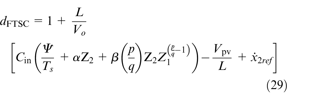
Under this control law, featuring a nonlinear MV given by equation (26), the state variables Z1 and Z2 converge to zero, ensuring finite-time convergence of the PV system errors trajectory to the attractor (t s given by equation (27)), and thus guaranteeing quick convergence to the MPP in the correct direction.
Stability and robustness analysis
To ensure stability, the design of an appropriate control law is imperative. Stability analysis is performed utilizing the following Lyapunov function:

Differentiating equation (30) yields to:

Utilizing equation (28), we derive:

Substituting the control law of equation (29) into
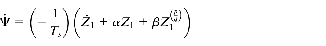
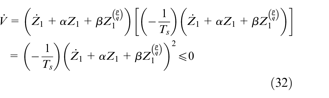
By utilizing equation (32), we obtain
Performance benchmarking
MPPT efficiency
The MPPT efficiency of various procedures is used to evaluate their effectiveness. The following equation is used to calculate instantaneous MPPT efficiency 12 :

The provided expression denotes the average efficiency of the MPPT:

Within equations (33) and (34), the variable PMPP* represents the utmost potential power attainable, which serves as the algorithm’s objective. It is determined through the employment of the PV model. Conversely, PMPP stands for the real power that the MPPT algorithm yields. Its value relies on the algorithm’s ability to closely match the instantaneous irradiance.
Tracking accuracy
In addition to efficiency, tracking accuracy is another crucial metric that assesses how well the MPPT controller follows the MPP under varying operating conditions. A common approach to evaluate tracking accuracy is through Root Mean Square (RMS) error analysis. RMS error provides insights into the average difference between the estimated power values generated by the controller and the actual power output of the PV system. A lower RMS error signifies better agreement between the estimated and actual power, indicating a more accurate and efficient tracking performance by the controller. The mathematical equation for calculating RMS error is as follows:

Where N represents the total number of data points, Pest(i) is the power value estimated by the MPPT controller at data point i, and Pact(i) denotes the actual power output of the PV system at data point i.
Simulation results and discussion
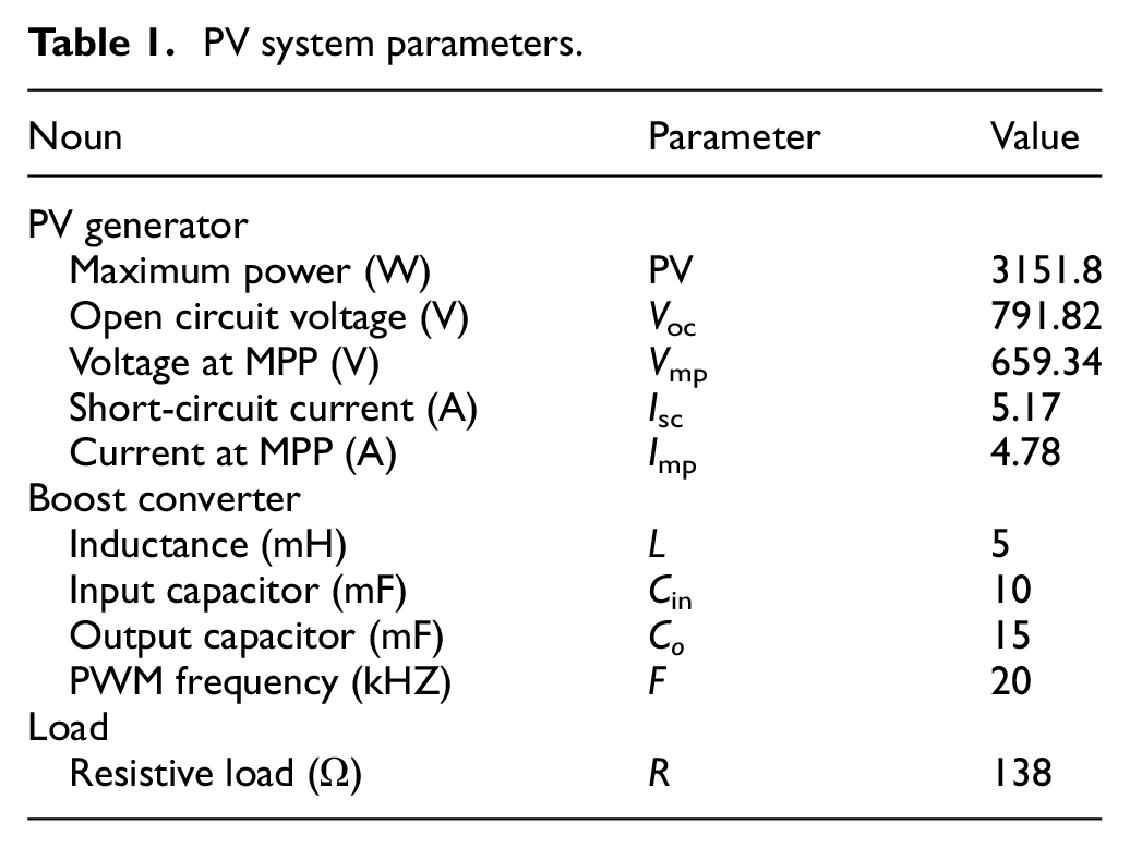
In this section, the durability of the suggested algorithm is assessed through comprehensive performance evaluations. The tests were conducted using the MATLAB/Simulink platform on a PC with an 11th Gen Intel(R) Core(TM) i5-1135G7 processor running at 2.40 GHz, and 8 GB of RAM clocked at 4267 MHz. To demonstrate its sturdiness, we benchmark the effectiveness of the suggested algorithm against FTSC approaches and the traditional P&O method, which continuously adjusts the PV operating point based on observed power variations, 11 and operates with a fixed perturbation step size of 0.005, ensuring a balance between tracking speed and stability. The system energizes a resistive load R, via a boost converter and draws power from a series of 18 “A10Green Technology A10J-S72-175” solar panels. The specifics of the simulation setup are delineated in Table 1. We scrutinize two separate scenarios that simulate diverse meteorological conditions impacting the PV panels.
PV system parameters.
Simulation results
The results are illustrated in Figures 7–14, encompassing a timeframe of 6.5 s across the irradiance assessment and 3 s across the thermal evaluation. To accentuate our unique contribution, each diagram shows a comparison between the PV power output attained via the ANFIS-FTSC approach versus the conventional P&O and FTSC methodologies. Furthermore, the figures present computations of the MPPT efficiency (ηMPPT) based on equations (34) and (35). The simulation was intended to corroborate the resilience and stability of the ANFIS-FTSC controller when responding to meteorological variations.
Solar irradiation test
The performance of the ANFIS-FTSC MPPT technique was assessed against two different MPPT algorithms at a fixed temperature of 25°C in the presence of varying solar insolation using the Ropp test, which was first suggested in a previous study. 55 The Ropp test involves subjecting the MPPT algorithm to varying solar irradiance conditions represented in Figure 6. This evaluation aims to determine the algorithm’s capability to handle both gradual and sudden changes in irradiance levels, as well as its response under the SteadyState condition. The test starts at an irradiance of 200 W/m2, gradually increasing to 1000 W/m2. Subsequently, four-step changes in irradiance are introduced: (1000–200), (200–600), (600–200), and (200–1000) W/m2. At last, the irradiance progressively drops from 1000 to 200 W/m2.
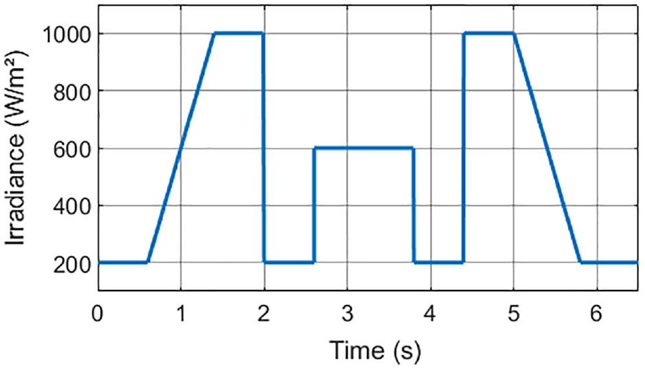
Ropp test irradiance profile.
Ambient temperature test
In this scenario, the algorithms were tested by simulating a significant temperature change while maintaining a solar irradiation level of 1000 W/m2. The temperature varied from 25°C to 35°C and then to 45°C over 3 s, as depicted in Figure 7.
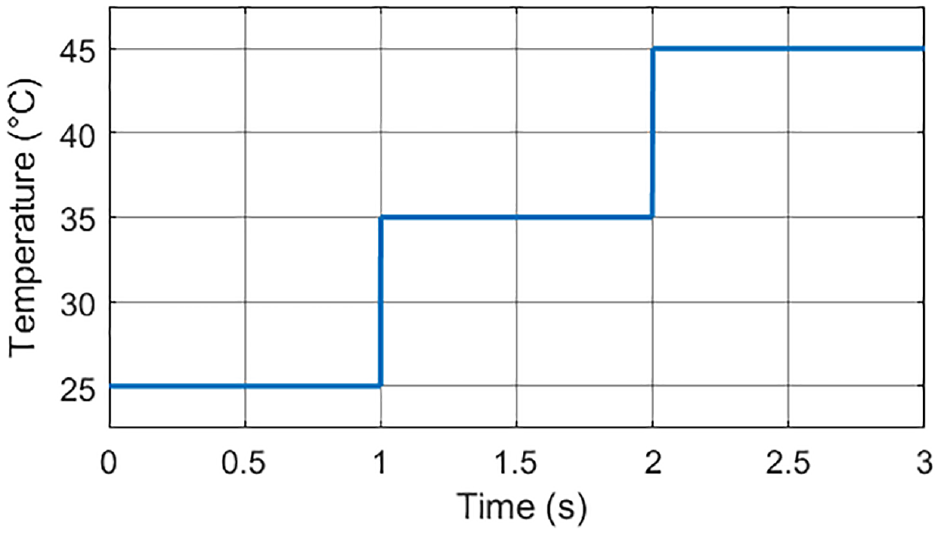
Temperature profile.
Discussion
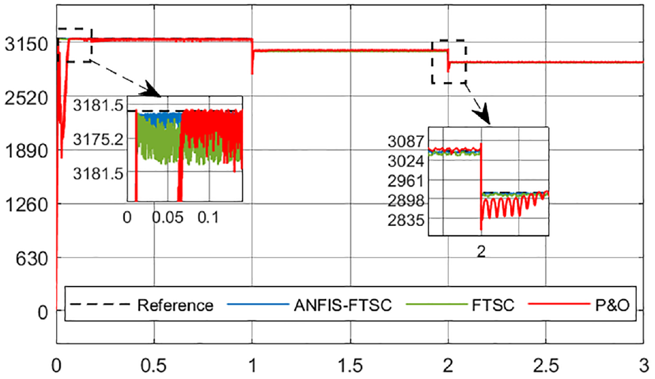
The tracking performance of various MPPT techniques can be assessed by analyzing the output power profile depicted in Figure 8 with its enlarged parts. In this scenario, three MPPT algorithms were evaluated: the P&O algorithm, the FTSC, and the ANFIS-FTSC.
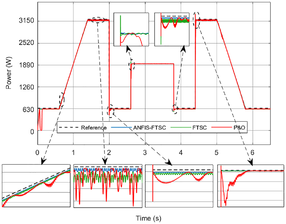
Comparison of the tracking performance of the different MPPTs.
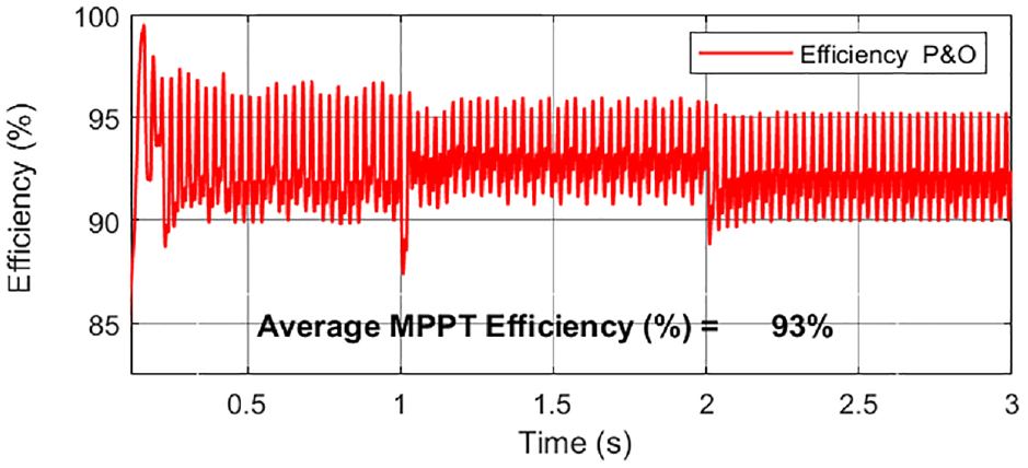
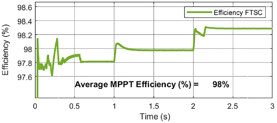
The ANFIS-FTSC MPPT exhibited exceptional accuracy in tracking the irradiance profile, demonstrating minimal oscillations and the shortest time to reach the MPP with an almost invisible perturbation size, and consistently maintained its tracking point. The FTSC MPPT, which shares some similarities with the ANFIS-FTSC MPPT, exhibited an effective tracking performance, but with a major limitation in tracking observed during the rapid rise and fall of irradiance, as shown in the expanded section of the figure. However, it quickly returns to the tracking point. Nevertheless, the P&O algorithm exhibited a longer tracking time, especially during start-up and after the loss of tracking direction during rapid irradiance changes. Furthermore, it displayed notable oscillations at high irradiance levels (4% of PMPP) and a tendency to lose the tracking direction with large oscillations during gradual irradiance changes (6% of PMPP), attributed to its fixed step size, as shown in the enlarged part of the figure. Examining the ηMPPT of the P&O algorithm, the FTSC, and the ANFIS-FTSC, as illustrated in Figures 9–11, and computed by equation (33), reveals interesting insights. The P&O algorithm exhibits efficiency oscillation ranging from 85% to 99.5%. Nevertheless, the efficiency plummets to as low as 55% in cases of tracking direction loss. In the case of the FTSC MPPT, the efficiency remains consistently around 99% for most of the time but experiences a slight decline to the 93% and 94% range during tracking divergence. In contrast, the proposed ANFIS-FTSC MPPT demonstrates minimal steady-state oscillation, which closely follows the power locus during changes in irradiance; even during the transient mode, it demonstrates smooth tracking of the power position, distinguishing it from other MPPT techniques. Throughout the whole Ropp profile cycle, the calculated average MPPT efficiency (ηMPPT(avg)), the P&O algorithm, FTSC MPPT, and ANFIS-FTSC MPPT are determined to be 95.6%, 97.1%, and 99.89%, respectively. These results highlight the superior performance of the proposed ANFIS-FTSC MPPT in achieving high efficiency and accurate power tracking throughout the cycle.
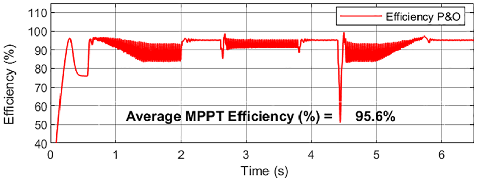
P&O efficiency profile.
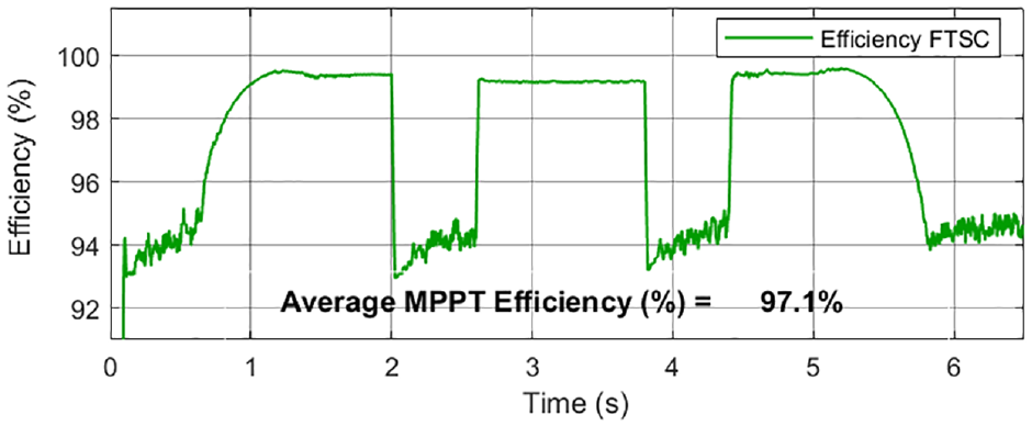
FTSC efficiency profile.
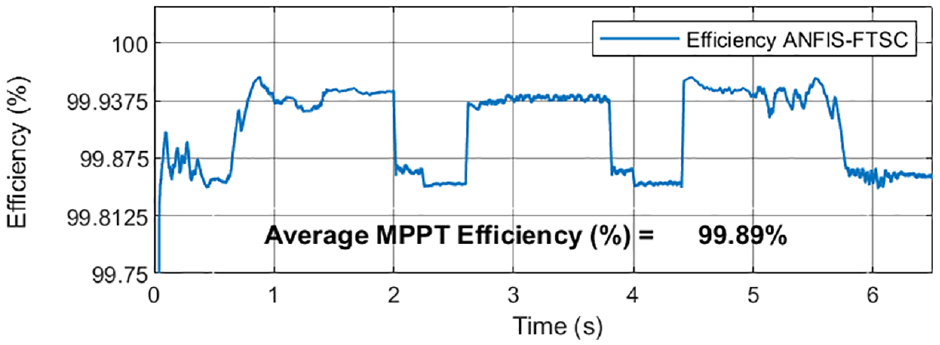
ANFIS-FTSC efficiency profile.
In Scenario Two, shown in Figure 12, there was a sharp rise in the ambient temperature levels, while the solar irradiance remained constant at 1000 W/m2. Figure 13 shows the ηMPPT of the solar panel’s power output for each control method. Significantly, all three controllers reacted more swiftly, with the conventional P&O technique displaying slower convergence and increased oscillations. The ANFIS-FTSC method works very well, adapting to changes without any issues. The efficiency graphs for each technique are presented in Figures 13–15. Due to repeated failures in the track direction, the ηMPPT(avg) of the standard P&O method dropped to 93%, whereas the FTSC approach maintained an efficiency of approximately 98%. In contrast, the proposed ANFIS-FTSC controller exhibits commendable tracking performance during both steady-state and transient operations, achieving an efficiency of over 99.87% across all scenarios. The ηMPPT(avg) of the ANFIS-FTSC controller approaches 99.9%, underscoring its high effectiveness in maintaining optimal power extraction under varying ambient temperature conditions.
PV Power generation under temperature test.
P&O efficiency profile.
FTSC efficiency profile.
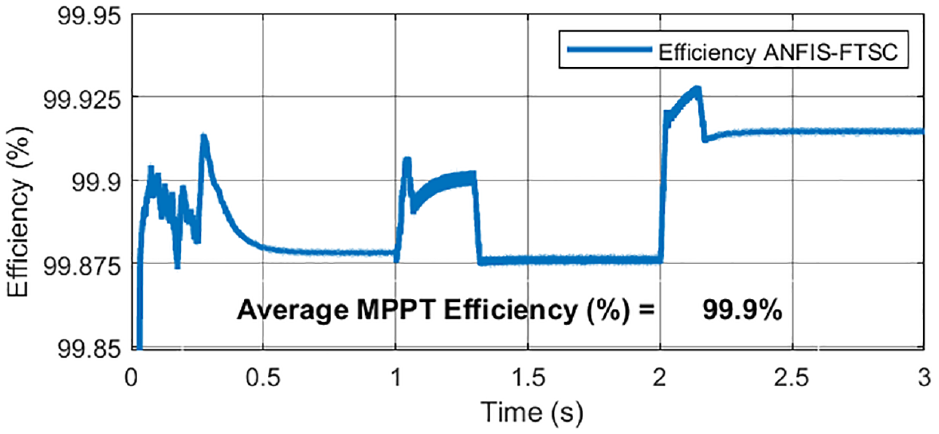
ANFIS-FTSC efficiency profile.
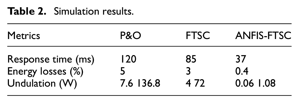
In conclusion, among the evaluated MPPT algorithms, the ANFIS-FTSC MPPT stands out as the superior technique. With exceptional accuracy in tracking the irradiance profile, minimal oscillation, and the shortest time to reach the MPP, it outperformed the other methods. To facilitate the performance comparison, Table 2 presents the key metrics for the three MPPT techniques discussed. These metrics include response time, undulation, energy loss, and efficiency. Its ability to maintain its tracking point with an almost invisible perturbation size demonstrates its robust and reliable performance, making it the best choice for efficient and precise MPPT.
Simulation results.
The table presented as Table 3, provides a concise comparative overview of the algorithm in question alongside other established algorithms. This comparison encompasses widely recognized methods such as ANN, FLC, ANFIS-TRSMC, ANFIS-BS, and conventional P&O-based MPPT algorithms, as these are frequently cited in scholarly works. Key performance metrics used in the evaluation include the rate of convergence, stability, and overall efficiency.
Contrasting the suggested algorithm with alternative algorithms.
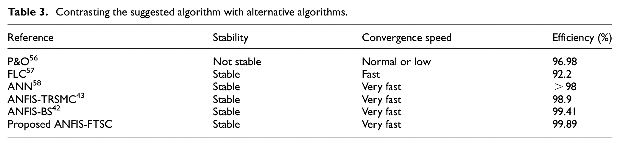
Table 3 provides a clear comparison between the proposed ANFIS-FTSC MPPT controller and the established algorithms. As is evident from the table, the ANFIS-FTSC method exhibits superior performance in terms of both convergence speed and efficiency. It achieves significantly faster convergence compared to P&O and other algorithms while maintaining a speed comparable to that of existing ANFIS approaches. Furthermore, the ANFIS-FTSC controller boasts the highest efficiency (99.89%) among all the compared techniques, achieving a notable improvement of 1.98% over the ANN and 0.99% over the ANFIS-TRSMC. This enhanced performance across both metrics underscores the effectiveness of the ANFIS-FTSC controller in managing power systems for MPPT processes.
To further evaluate the tracking accuracy of the proposed ANFIS-FTSC controller, we conducted a Root Mean Square (RMS) error analysis. RMS error provides insights into the average difference between the estimated power values generated by the controller and the actual power output of the PV system. A lower RMS error signifies better agreement between the estimated and actual power, indicating a more accurate and efficient tracking performance by the controller. To further assess the tracking accuracy of our ANFIS-FTSC controller, we conducted an RMS error analysis alongside established algorithms detailed in Table 4. 59
RMS error.

It is important to acknowledge that, like any approach, the ANFIS-FTSC MPPT controller has some potential limitations to consider for future exploration. One area of investigation could be its computational complexity. While the current implementation performs well in simulations, deploying it in real-time systems with limited processing power might necessitate further optimization techniques to ensure efficient operation. Additionally, this study focused on uniform irradiance. Real-world solar power systems often experience dynamic operating conditions, including partial shading due to obstacles like buildings, trees, or nearby equipment. Future research could explore the effectiveness of the ANFIS-FTSC controller under a wider range of conditions, particularly partial shading. This would provide a more comprehensive understanding of its generalizability and potential for broader application in diverse solar power system deployments.
Despite these considerations, the ANFIS-FTSC controller demonstrates significant promise for MPPT in solar power systems. Its superior performance in terms of convergence speed, efficiency, and tracking accuracy, as highlighted in Tables 2–4, makes it a valuable contribution to the field.
Conclusion
The application of an innovative nonlinear fast terminal synergetic controller, guided by an artificial neuro-fuzzy algorithm, has demonstrated remarkable effectiveness in optimizing power extraction from the PV-boost converter system. The system’s global stability is ensured through the utilization of asymptotic stability principles, validated by the Lyapunov function. Rigorous simulations conducted in the MATLAB/Simulink environment, accounting for variations in solar irradiance and ambient temperature, have verified the robustness and reliability of our proposed method. Our MPPT solution achieves an exceptional efficiency rate of 99.89%, signifying a significant advancement over existing methodologies. For this purpose, future efforts will focus on confirming the outcomes predicted by our simulation through practical experimentation.
Footnotes
Declaration of conflicting interests
The author(s) declared no potential conflicts of interest with respect to the research, authorship, and/or publication of this article.
Funding
The author(s) received no financial support for the research, authorship, and/or publication of this article.
Ethical approval
Ethical approval is not applicable to this study as it did not involve human or animal subjects.
Data availability statement
The data underlying this article will be shared on reasonable request to the corresponding author.