
Abstract
The construction of a rigid body biomechanical model with higher ordered controller design is a challenging task due to the complicated architecture and complexity of human intended movements. Biomechanical analysis of such complex model for sit-to-stand (STS) movement in three dimensions (3D) requires the envisioned actions of humans by utilizing motor controls. The current study aims to enhance our investigation into 3D bipedal mobility by creating optimal control for our novel Twist and Tilt foot mechanism. Unlike earlier models, this mechanism does not assume any fixed foot for the entire profile. This novel model type enables one foot to perform a twisting motion and the other foot to execute a sliding tilt motion. This technique simulates the control effort needed during the STS task by individuals with neurological impairments while performing various joint positions. The twist and tilt model is created using computer-aided design (CAD) software SOLIDWORKS, utilizing an 8-segment biped. The linearized model in SIMULINK generated 24th ordered State Space model. Subsequently, we developed LQR (linear quadratic regulator) controller for attaining the desired trajectories in MATLAB/SIMULINK. This novel twist and tilt optimal control strategy have improved angular profiles and simulation results showcase the stroke patient’s movements with one foot sliding deficient tilt and other foot twisting during the profile.
Keywords
Introduction
Bio-Mechanical Systems is a field of engineering that specifically examines the mechanics of biological challenges. There has been extensive research recently on designs of biological beings that exhibit voluntary motions, anthropomorphic characteristics and motor control. This research aims to promote rehabilitation robotics, motion control, and other biological advancements. Further examination involves the intricate modeling of the human musculature, which exhibits a highly non-linear function. Most of these musculoskeletal models are created using software tools such as SD/FAST or similar alternatives. Among this research, the rigid body model of human mechanics is a crucial topic that needs immediate attention for the analysis of planned human movements. Generic rigid-body models are computationally intensive, but an increasing number of degrees of freedom (DOF) in the model can result in a significant amount of complexity. The researchers exploring rigid body models are primarily interested in joint synchronization, stability of postures, balance, and biomechanical instances such as design, control, and diagnostics of prosthetics, balance recovery, in-motion stability, fall prevention, and neuro-muscular interaction. Furthermore, the biped’s attached structure significantly increases the complexity of the model, necessitating a thorough analysis of controller design.
In our recent publications,1,2 we conducted a study on three different bipedal structural designs to examine the limitations on the movement of the rigid body model during the Sit to Stand (STS) motion. These models were based on the design on one foot fix and other foot one degree of freedom (DOF) joint. Afterward, we presented the sliding tilt forward thrust model 3 on the same one-foot fix and other one DOF joint by introducing the velocity trajectories in the reference profiles. Control scheme for sliding tilt forward thrust mechanism is designed in Ali and Mughal 4 to follow the reference trajectories of velocity based forward thrust model. However, it was realized that for devise assisted STS, motion of feet needs to be enhanced toward both feet movements. 5 Same was also required for rigid body models in 3D of biped.
We further extended our rigid body model for STS maneuver by introducing the movement of both feet in the model. 6 Using these movement patterns with both feet is beneficial for improving the postural stability of stroke patients while performing the STS movement. We presented two separate tilt configurations: a sliding tilt and a rotational tilt. Controllability and Observability analysis on both models revealed that the model with sliding tilt is full rank controllable and observable and is best suitable for controller design. This research focuses on providing the optimal control strategy7,8 developed for our innovative twist and tilt model, specifically built to accomplish the STS problem. Designing controls for systems with both non-fixed platforms is a highly challenging endeavor, especially when the model has a high degree of freedom. This necessitates a significant amount of control effort to achieve the required movement. Therefore, we propose the implementation of optimal control for a system consisting of 24 outputs regulated by 11 inputs. The specified outputs provide the positions and velocities of all joints that are controlled by 11 joint input torques.
Our model comprises of a 3D biped with eight rigid body segments, including two feet, two calves, two thighs, one pelvis, and one Head Arm Torso (HAT) segment, as depicted in Figure 1. This unique design has a 24th ordered system, where the left foot is a sliding tilt along the frontal plane, while the right foot can twist along the sagittal plane. This design is more physiologically appropriate compared to the prior 22nd ordered system, which considered the left foot as a joint with zero degrees of freedom. Moreover, the system also eradicated the redundant holonomic constraints of earlier designs9–12 to make the design suitable to human’s gait during STS maneuver. Subsequently, a novel optimal feedback controller design is necessary for the non-linear model of twist and tilt. The biped’s 3D model is created utilizing the CAD software SOLIDWORKS. 13 Afterward, these models are imported into SIMSCAPE 14 for control synthesis. The SOLIDWORKS model is a CAD that is experienced in motion analysis and assembly design analysis for biped joint modeling. It can concurrently operate on LabVIEW 15 as well as SIMSCAPE 14 model, a software platform for creating computational models of physical systems. SIMSCAPE language, built upon MATLAB, 16 aids in creating textual descriptions for physical modeling domains, enabling the generation of customized component models. Optimal Control is designed using MATLAB/Simulink. Two Main Contribution of this research is summarized as below:
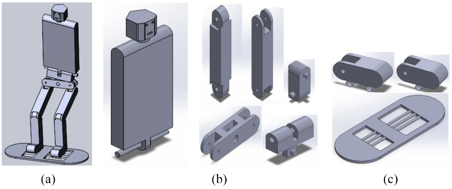
CAD model of twist and tilt biped: (a) CAD assembly for twist and tilt, (b) part level model for HAT, pelvis HAT segment, hip, thigh, calf, and (c) part model for left foot, right foot and base plate.
Generation of a novel twist and tilt foot scheme to showcase the human intended movements of stroke patients.
Development of Optimal Control for twist and tilt model to carry out human voluntary motion of Sit to Stand (STS) to mimic the stroke patient.
This paper is ordered as following. Section 2 presents the recent advancements in the Bio-mechanical systems with relevance to rigid body and muscular models. In Section 3, the Twist and Tilt bipedal model is presented with the computer aided design (CAD) part and assembly level modeling schemes. Mathematical description of coupled twist and tilt bipedal model is presented in Section 4. Section 5 describes the optimal control for the twist and tilt model to achieve sit to stand (STS) along with the implementation of model in SIMULINK/MATLAB. Simulation results are explained in Section 6 and finally the research conclusion and future directions are presented in Section 8.
Related Literature
Biomechanical systems are focused on motor controls and requires optimal control structure to study the human intended behavior. Optimal control in Humaidi et al. 8 is utilized for control of glucose level during the insulin injection process. Another adaptive control system in Ajel et al. 7 is developed for maneuver of Tail-Sitter VTOL Aircraft subjected to gust and wind disturbance. Another work 17 described optimal approach to human behavior learning mechanism. A novel CL based adaptive law is updated to estimate the human feedback gain matrix by removing the persistent excitation through traditional adaptive methods.
Bio-mechanical systems have a broad range of applications in understanding and enhancing rehabilitative robotics. Preliminary rigid body simulations of biomechanical motions were primarily concerned with the biomechanical structure of tiny segments. The models used in Hemami and Jaswa 18 and Pai and Iqbal 19 primarily focus on sagittal planes and provide representations of postural stability and mobility for only three or four segments. These small segment models include primarily of biological parts such as the foot, calf, thigh, and Head Arm Trunk/Torso (HAT) segments. Researchers20,21 utilized a biomechanical model consisting of a stiff body with three links to simulate sagittal plane movements, balance recovery, and postural stability. The assembly of three links represents a representation of a triple inverted pendulum. The intrinsic instability of this paradigm necessitates a continuous application of control effort, specifically in the form of joint torques, to uphold a stable posture. The attainment of postural stability using PID controllers involved the utilization of both two-segment and four-segment models. This study examined the capacity of both the linear inverted pendulum (LIP) model and the variable-height inverted pendulum (VHIP) model to predict the stability of the capture-point (CP) in a single stair climb model. 22 The outcome indicates the constraints of Inverted Pendulum design’s gait, mostly due to significant hip and knee moments.
Older biped models employed Maple’s Dynaflexpro 23 toolset to construct biomechanical models. 10 The DynaFlexPro model, invented in Maple, comprises of distinct components for the feet, shanks, thighs, pelvis, and the head, arm, and torso (HAT). In their work, the authors of Mughal and Iqbal 12 presented a model that incorporates three holonomic constraints. They also explored the development of an optimal controller that is independent of these constraints. Mughal and Iqbal 24 describes a distinct study that specifically examines the process of synthesizing the human voluntary sit-to-stand (STS) maneuver. The study in Burnfield et al. 5 demonstrates a variety of patterns in human movement during the sit-to-stand motion. The observed movements are obtained from persons with paraplegic disabilities, requiring the conversion of the model from unilateral foot movement to bilateral foot movement. Observers have seen a slight rotation and inclination during the transition from sitting to standing in persons with neurological abnormalities that affect both feet. The researchers in Janssen et al. 25 performed a thorough examination of action factors (predictors) in the domain of STS (Sit-to-Stand). The Sit-to-Stand (STS) action has been classified by numerous physiologists into distinct stages, such as forward thrust and extension. 26
All models based on rigid body mechanisms necessitate specific control efforts to achieve the desired response. Control techniques such as Fuzzy reduced order observer 27 and Adaptive Neural Fuzzy, 28 along with optimal control methods like LQR, 29 can effectively solve non-linear problems. However, as model’s complexity increases, it become more challenging to handle higher order system to perform human voluntary tasks effectively.
In the past, we designed three modeling methods 1 to examine the limitations on movement of the human being STS rigid body concept. Figure 2 illustrates three possible configurations of the model. We additionally developed the optimal control strategy for the model consisting of one fixed foot and an additional degree of freedom (1DOF). 2 Subsequently, we examined the forward thrust characteristics 3 of the identical model by incorporating velocity variables and formulating the control technique. 4 Nevertheless, these investigations lack physiological relevance in the context of studying the stance and gait of neurologically impaired individuals, as they involve one foot being immobilized on the ground. Thus, it is necessary to develop a more precise model that incorporates both feet movements to precisely replicate the sit-to-stand motion of individuals with neurological impairments. Moreover, control development of such both feet moveable mechanism is also a major requirement that can impair with the Central Nervous System (CNS) to idealize the STS of physically disabled persons.
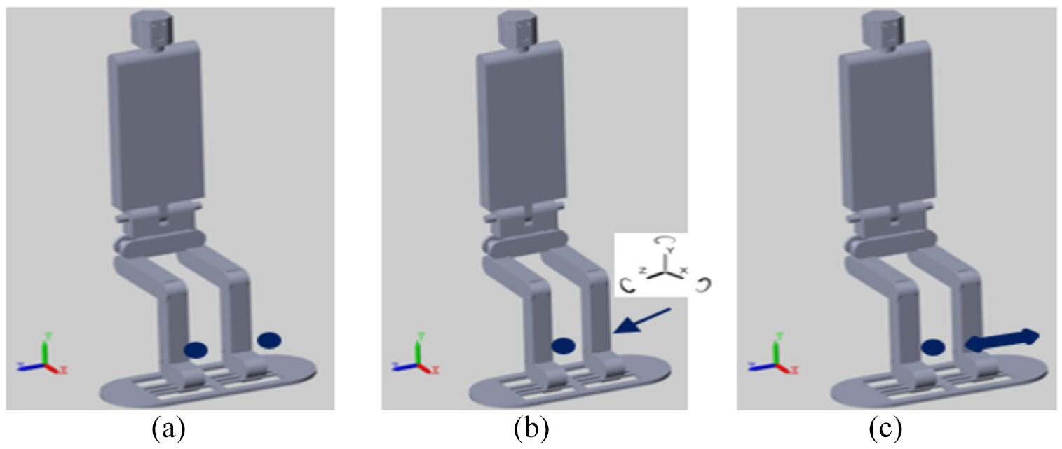
One fixed foot configurations for biped: (a) both foot fixed, (b) one fix and other 6DOF, and (c) one fix and other 1DOF.
Dynamic twist and tilt bipedal model
Contrary to one fixed foot arrangement for bipedal STS, we have developed a dynamic 3D biomechanical model that incorporates one foot twist and other foot a sliding tilt mechanism (Figure 1). The approach outlined in this work is derived from the motion pattern found in immobile mechanisms employed by individuals with stroke. 5 Figure 1(b) presents the part level model for HAT, Pelvis HAT segment, Hip, Thigh and Calf. Further part model for Twist and Tilt Left and Right foot along with Base Plate presented in Figure 1(c). Integrating bilateral movement patterns that engage both feet provides advantages in enhancing the postural stability of stroke survivors during the STS maneuver. The part level model in 3D for the said biped is developed in computer-aided design (CAD) software SOLIDWORKS 13 as shown in Figure 1(b) and (c). The bipedal model comprises a total of eight segments, which collectively constitute its structure. The components consist of one Head Arm Torso (HAT), one Pelvis, two thigh segments, two calf segments, and two-foot parts. The left foot model features a sliding tilt mechanism in the frontal plane, while the right foot model is a rotational twist model along the sagittal plane. Additionally, there exists a distinct part-level model of the Base the said configuration.
Joint architecture for twist and tilt assembly
After methodically designing the parts to match the measurements of an ordinary human individual, the next phase is to construct a dynamic design at the assembly level. This is accomplished by employing 3D mates for biped, as illustrated in Figure 1(a). The design of the mates considers the kinematic principles that control the functioning of revolute and universal joints. A revolute joint allows for the authorized rotational movement between two frames, thereby linking two distinct rigid segments within a fixed frame of reference. The input torque for this setup is theoretically expressed as a single variable, which will then appear in the dynamic equations explained in next section. The universal joint enables just two perpendicular rotations between two coupled frames. The system’s dynamic equations include two distinct rotating joints inside the framework of two perpendicular axes. The system utilizes the “applied moment” module to incorporate external torques as input.
The proposed model includes a biped schematic that consists of 10 joints, specifically seven sagittal joint angles ℓ1–ℓ6 and ℓ9. These total 7 articulations consist of two ankle joints, two knee joints, two hip joints, and one pelvic-hat joint. The three rotating joints, specifically ℓ7, ℓ8, and ℓ10, are in the frontal planes. Figure 3(a) and (b) displays the sagittal and frontal plane joints of the model. The set of articulations consists of two frontal hip joints and a single frontal pelvic-hat joint. Within the domain of joint configurations, it is important to highlight that a single Pelvis-HAT joint and a pair of Hip joints demonstrate the qualities of universal joints, with a combined total of two degrees of freedom (one in the sagittal plane and another in the frontal plane). In contrast, a pair of ankle joints and a pair of knee joints are categorized as revolute joints with one degree of freedom.
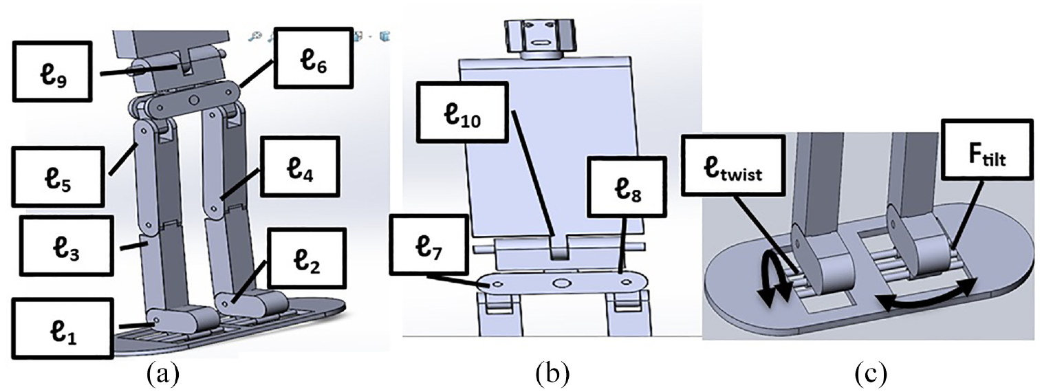
Joints schematics of twist and tilt model: (a) sagittal plane joints, (b) frontal plane joints, and (c) feet configurations for twist ant tilt joints.
The most crucial schematic of the bipedal model, with regards to the sit to stand action, is the configuration of twist and tilt, which is based on the kinematic linkages of the feet. Within this organization, the Left foot possesses a rotary joint that permits twisting along the sagittal plane axis, while the right foot is equipped with a sliding/linear tilt joint that operates in the frontal plane axes, as depicted in Figure 3(c).
Twist and tilt coupled dynamic model – mathematical description
The twist and tilt coupled model incorporates ten joint positions, designated as ℓ1–ℓ10, joint velocities, represented as
Twist and tilt model implemented in simulink.
Consider the vector


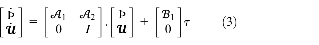
The state space model corresponding to the equation (1) is presented below:

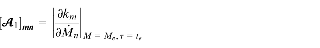
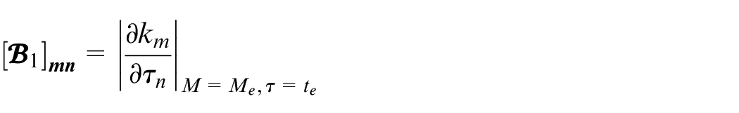
In the given state space model, equation (2), the matrix
Equation (2) is the non-linear state space model of the twist and tilt model. It consists of 14 non-linear functions. The non-linear model is utilized to create a linearized schematic of the system specified in equation (3).
Linearization of the model at linear positions is required to become operative inside the linear bounds of operation. The operating conditions for STS task is from seated position toward standing position. This is required to generate stable optimal control inside the operational limits of the model. Therefore, we obtain the state space transformation at the stable positions of the biped. For control point of view, controller is designed to control the nonlinear dynamics of the model based on linearized model. Control strategies are explained in detail in Section 5. Here, equation (3) is the linearized state space model consisting of 14 states.
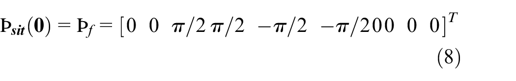
In our Rotational Twist and Sliding Tilt configuration, Right foot is a rotational joint along the sagittal plane, whereas Left foot is a translational joint along the frontal plane. The joint angles and positions along with velocities for Twist and Sliding Tilt model is presented below.


The model is linearized within the sitting and standing positions, where the joint positions are mentioned in equations (7) and (8).

For State-Space origination of complete system, we utilize SIMULINK Model Linearization toolbox
16
to obtain the linearized model. This linearized model is subsequently utilized for developing control strategy. The model’s standing position linearization occurs when
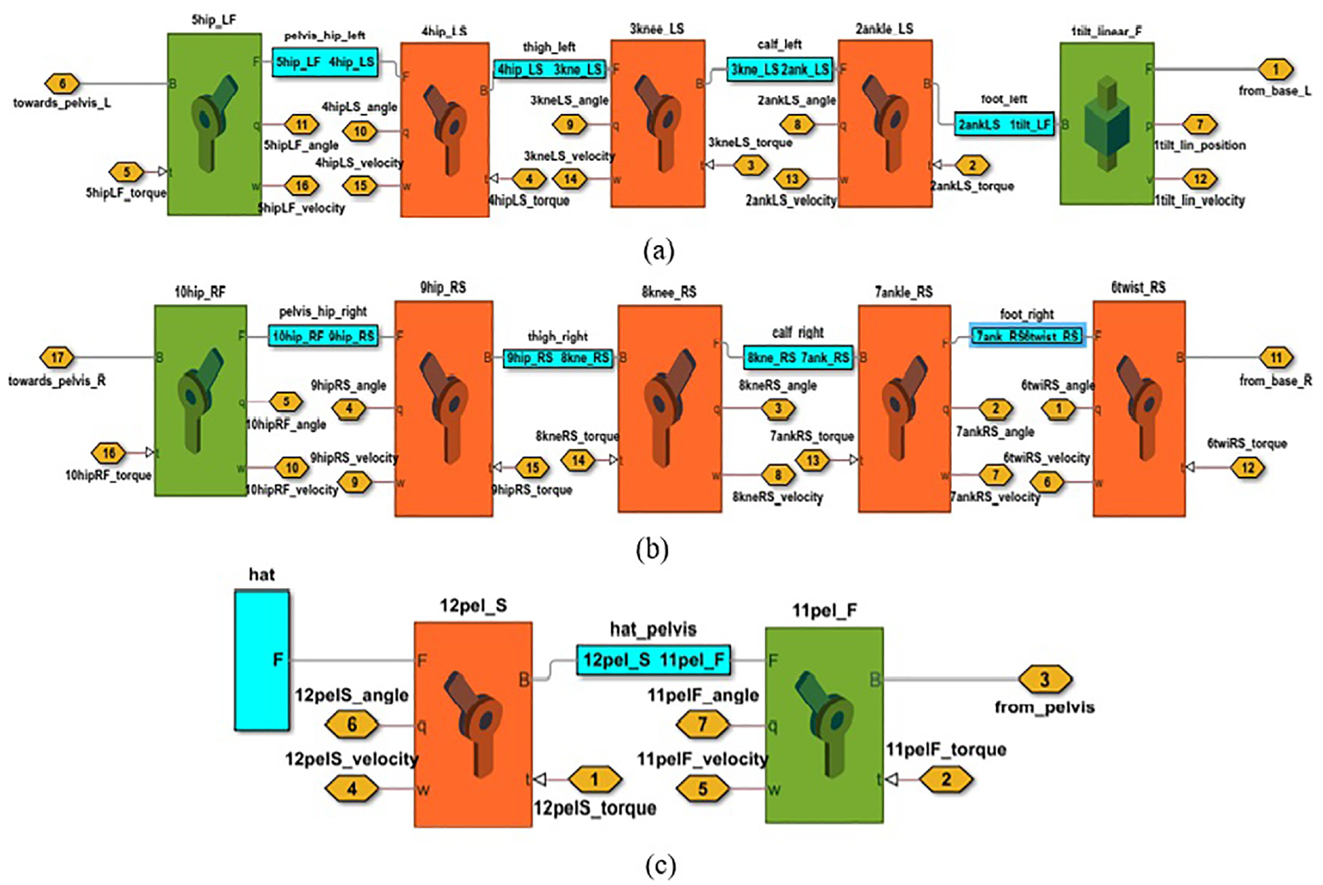
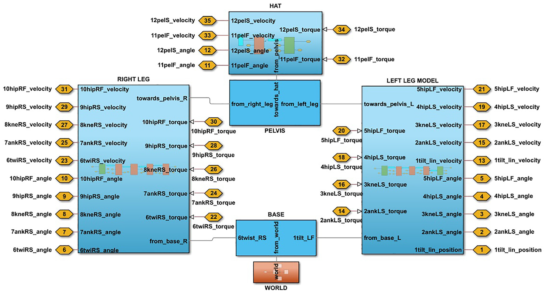
3D bipedal model implemented in Simulink for STS: (a) model for left leg, (b) model for right leg, and (c) model for hat and pelvis.
Optimal control for twist and tilt model
To accomplish the task for STS, Optimal Control for controlling 14th states system with 12 inputs and 24 outputs is essentially required. Related Systems such as Aljuboury et al. 30 utilized the state and output feedback controller based on the stability analysis utilizing the Lyapunov theorem for the exoskeleton knee system. Another work 31 utilized adaptive backstepping controller as well as sliding mode controller for accomplishing the task of electronic throttle control for valve. Research on wearable knee assistive system in Mahdi et al. 32 utilized synergetic adaptive control to accomplish the knee-rehabilitation design for the patients suffering from knee disorders.
The biomechanical-bipedal STS challenge is a highly demanding field that necessitates the development of an exceptionally effective controller design, owing to the system’s considerable flexibility and degree of freedom. This role is specifically associated with the central nervous system in biological subjects. In our prior publications,1–4 we have introduced the most efficient control algorithms for STS with one foot stationary and the other foot having a linear joint. In this study, we are enhancing our optimum control approach by incorporating the optimal gains of the controller for a model where the left foot exhibits a rotational twist along the sagittal plane and the right foot displays a sliding tilt along the frontal plane. A model that permits both feet to twist and tilt is more physiologically applicable for stroke patients.
Designing a controller for such a system, where both base joints are controlled via torque inputs, is an exceedingly challenging undertaking. We have developed a state feedback optimum controller for the twist and tilt system, considering the need for twist and tilt. The model used in this design has both full rank controllability and observability. The system’s controller implementation for the twist and tilt plant in MATLAB/Simulink is depicted in Figure 6.
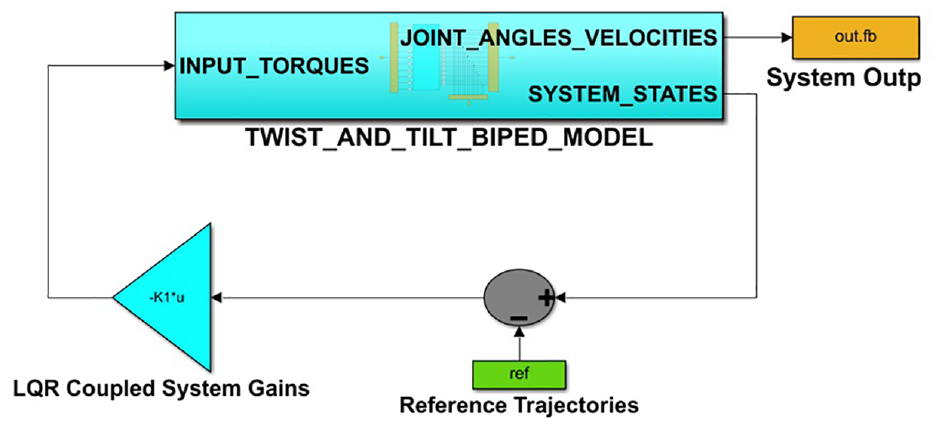
Optimal control schematics in simulink for twist and tilt model.
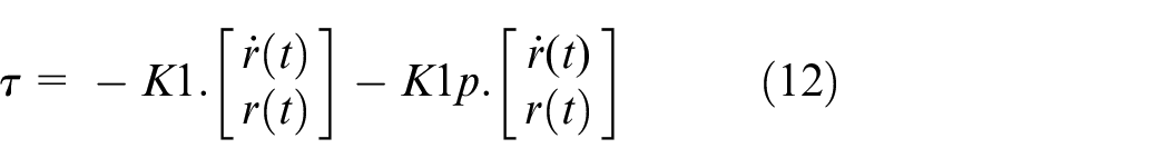
Equation (3) represents a linearized twist and tilt model that is an open-loop unstable system. Hence, to execute the STS movement, it is necessary to employ an efficient controller with the input

Determination of State Weighting matrix Q and its input weighting matrix R is based on various parameters, including the desired control specifications, the initial state and velocity, the final state and velocity, as well as the steady state response requirements of the system. The enhancements are assessed separately for each independent system. The following matrix depicts the overall gain of the generalized controller.

Here,
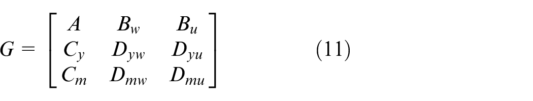
Model matrix A and B u in the system matrix M are associated with equation (3). Matrix B w depicts exogenous perturbations in the system. Matrix Dmw contains a set of input disturbances that have a row rank that spans the entire matrix, while the matrix C m provides an assortment of state measurements. Matrix C y and Dyu display controlled state and input parameters, respectively, but for matrices Dmu and Dyu it is typical to be zero-valued. Figure 7 displays the state diagram of the whole twist and tilt system for controller design, including the input torques and feedback angles/velocities. This diagram was built using MATLAB/Simulink.
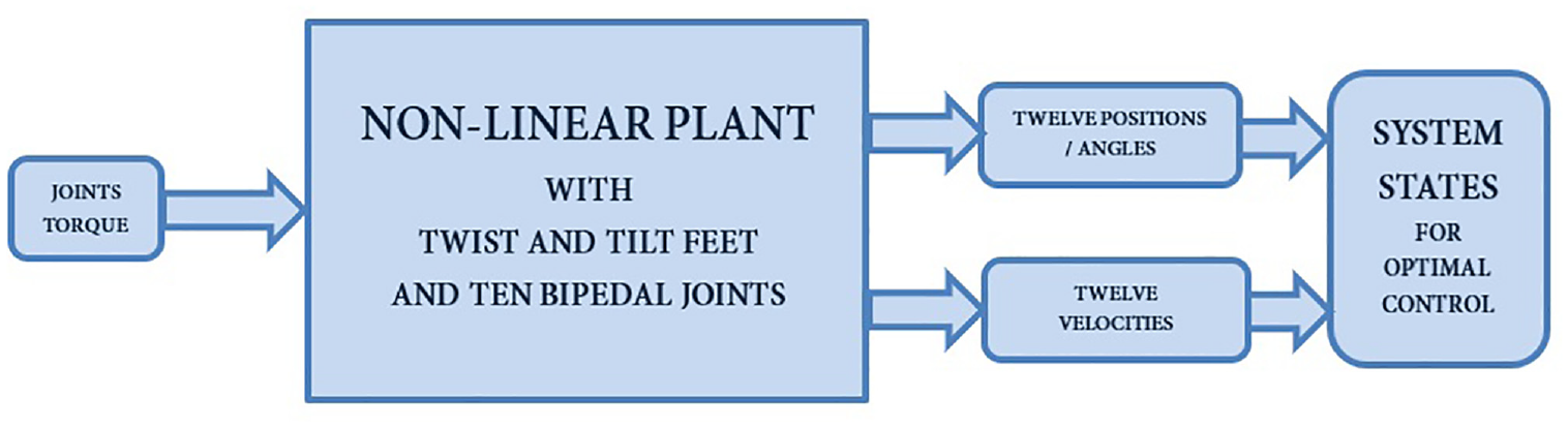
3D human biped plant for controller design.
For the successful execution of control law, the planned system shall meet the following necessities:
a.
b.
c.
d.
The nonlinear model requires a specific torque input to ensure stable STS movement, which is achieved by fulfilling these parameters.
Furthermore, we have integrated the subsequent conditions into our model to guarantee its stability:

To fulfill the specified criteria for LQR design, we have conducted trials with several weight configurations for the Cy, Dyu, and Dmw matrices, which will be employed in the System Matrix M. The established Linear Quadratic Regulator (LQR) control technique is applied to the above-described model using MATLAB/SIMULINK and the simulation results are presented in the subsequent section.
Results, simulation, and discussion
Twist and Tilt bipedal model for STS as explained earlier is designed in SIMULINK and is shown in Figures 4 and 5, whereas the optimal control schematic along with the state interconnection details is presented in Figures 6 and 7. The optimal controller gains for LQR based strategy is calculated in MATLAB and is then utilized in SIMULINK model of Figure 6. The complete system has a total of 24 outputs, which are controlled by 11 inputs through 14 states. The controller gain matrix K1 is therefore of the order 11 × 14.
We utilized the physical and kinematic attributes of twist and tilt model to replicate the behavior of the non-linear system. This was achieved by incorporating the reference values of all the angles and velocities, along with left foot sliding tilt movement and velocity, and the right foot twisting movement and velocity. As stated in the control scheme, the error E(t) is computed for each of the 24 outputs based on the reference trajectories for each of the state variables, that is, joint angles and joint velocities. Controller Gains Kl subsequently actuates the nonlinear twist and tilt plant by applying joint torques. The output torques serve to stabilize the nonlinear model when it transitions from a sitting position to a standing location by accurately tracking reference trajectories. This LQR based controller design produces much better results than previous PID or ANFIS based techniques utilized for STS transfer in Rafique et al. 28 and Sultan et al. 35
Figure 8 depicts the simulation of a biped at various time intervals during a total simulation duration of 5 s. It can be clearly seen that additional effort on the twisting foot is required to attain the desired STS task. This shows the case of neurologically disabled person where the additional effort on the healthy side generates the twisting impact on the healthy foot. This generates the impact of tilt on the lacking system and thus there is a sliding tilt in the left foot joint. In order to compensate for twist and tilt scheme, additional controller effort is required to follow the reference trajectories of all the joints.
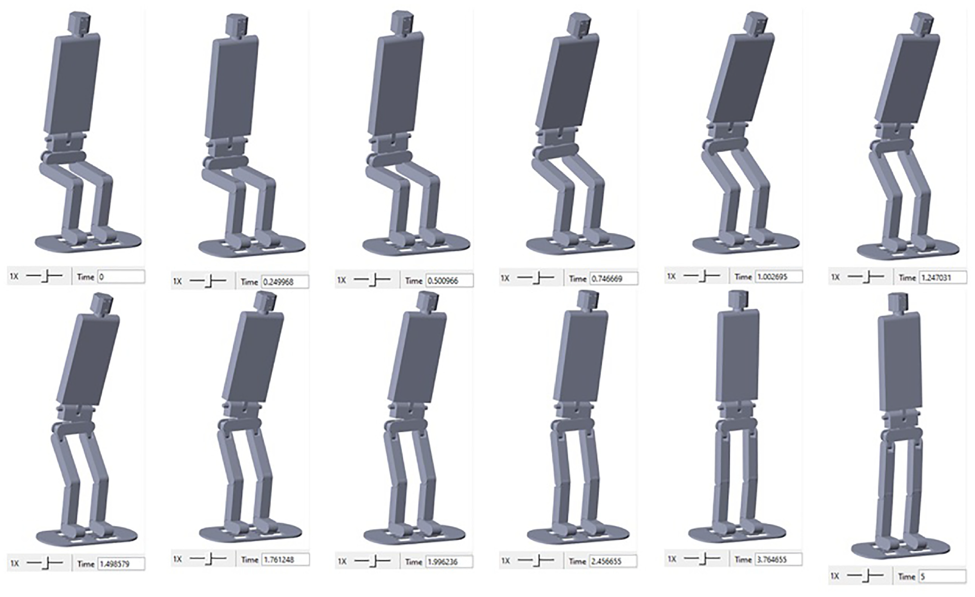
Twist and tilt model simulation during 0–5 s.
Furthermore, Figure 9 displays the outcomes of the system’s locations in comparison to the intended positions (reference trajectories) for the twist and tilt system. The controlled output is shown by blue lines, while the intended feedback is represented by red lines. The locations of all these entities are controlled by input torques that are provided to the system in accordance with LQR regulation for the twist and tilt models. The presence of a prismatic joint of frontal plane on left leg leads to a leg with neurological impairment in this study. This neurological condition causes involuntary muscle contractions in the right foot, resulting in significant difficulty in controlling its movements.
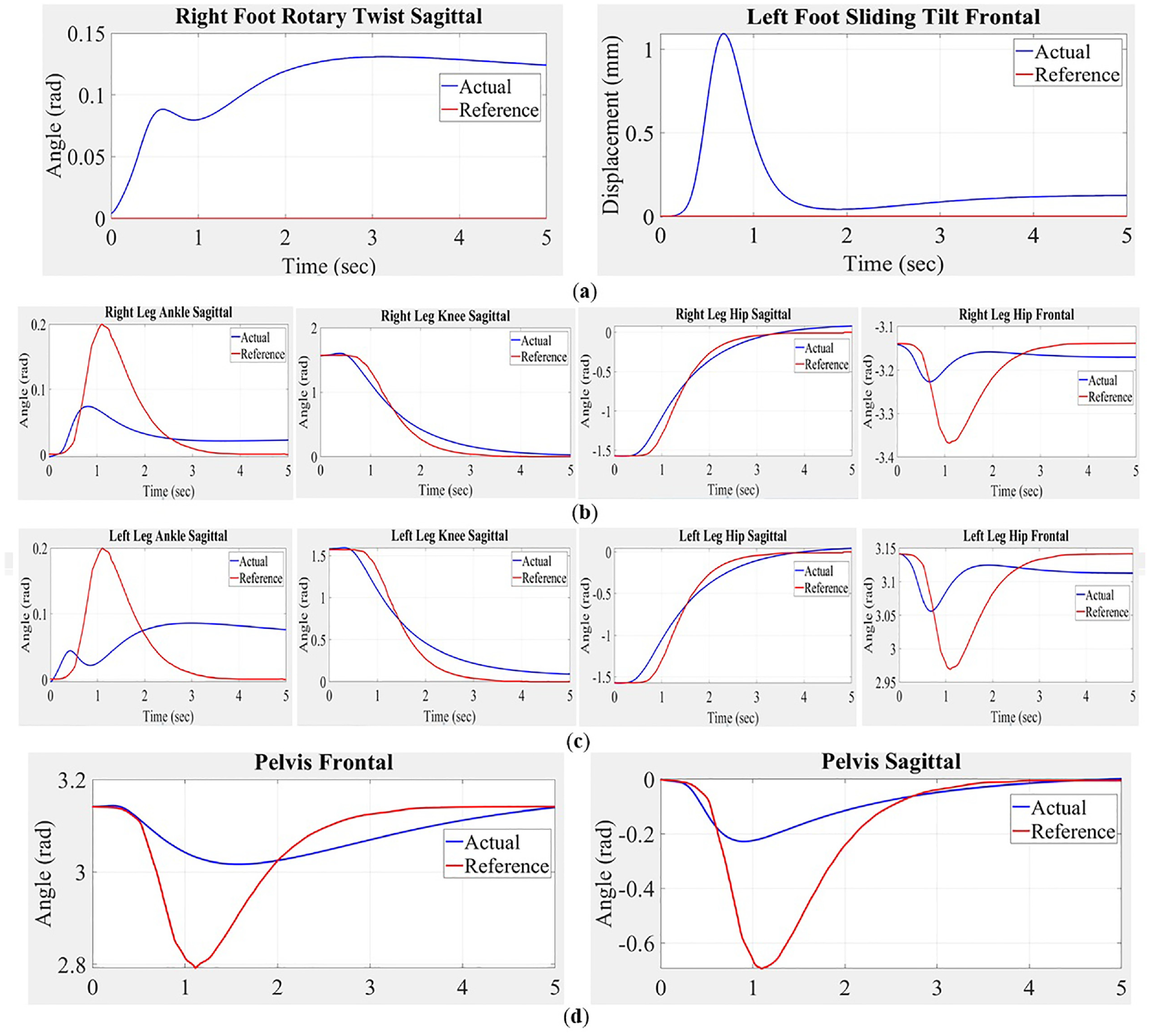
Actual positions versus reference trajectories: (a) twist and tilt joints, (b) right leg joints, (c) left leg joints, and (d) pelvis joints.
The simulation results clearly demonstrate that the angles of all joints in both the left and right legs accurately track the reference trajectories. Nevertheless, there is a 1 s delay in the frontal hip joints of both legs. Furthermore, there is an approximate inaccuracy of 0.3 rad at hip frontal and ankle sagittal joints of both legs during the first 2 s of the simulation. The existence of a twisting and tilting mechanism is necessary to stabilize the motion of these two joints. During the simulation, there is an error of approximately 0.4 rad in the Pelvic Hat joint along both the frontal and sagittal planes until it reaches 2 s. This is done to offset the increased level of flexibility in the system when compared to previous modeling systems. Furthermore, the response time of all the joints is approximately 100 ms. This is due to the flexible dynamic structure of the CAD model and non-involvement of physical components. demonstrate that the system achieves a maximum of 90% accuracy compared to the reference values within a time frame of 2.45 s. Additionally, the system closely tracks the reference trajectories within the desired boundaries.
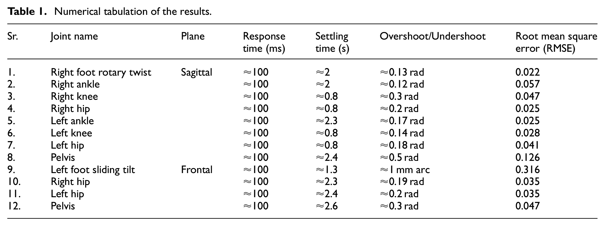
The sliding tilt joint of left foot has attained the arc length of 1 mm at 0.87 s. This is because of the motion of neurologically disabled person where load bearing capacity of deficient leg makes the leg to slide along the frontal plane. Same is shown in the simulation results of Figure 9. There is also a twist of 0.13 rad in the right foot along the sagittal plane. These results incite the instance of stroke sufferer having a neurological deficient left leg with a sliding tilt and necessitate supplementary effort on right leg which generates the twisting impact to cater for the desired trajectories for STS. Root Mean Square Error for each joint is computed which shows that the maximum RMSE appears on the deficient sliding tilt joint that is, 0.316. The numerical tabulation of Response time with the error in the results for each of twelve joints are tabulated in Table 1.
Numerical tabulation of the results.
All of the aforementioned studies provide evidence for the validity of the twist and tilt model, suggesting that it is a compelling explanation for neurological impairments. The findings indicate that the selected gain matrix for the twist and tilt model is the optimal method for regulating the sit-to-stand transition of the bipedal model. This model is initially constructed using CAD software and subsequently controlled using LQR in SIMULINK/SIMSCAPE. The Eigen values of the system are presented as an ordered pair, indicating that the system’s response falls within a manageable range.
Conclusion and future direction
Rigid body systems in modeling provides numerous fascinating opportunities for designing the controller at realm of modeling and managing the bipedal beings. This research utilized computer-aided design (CAD) methodology to create a biologically enthused motor control to simulate bipedal mobility. This model utilizes a unique twist and tilt foot mechanism, which is a specific adaptation of the sit-to-stand movement commonly observed in individuals with neurological disabilities. Following that, an Optimal Controller is developed to assist in the sit-to-stand transformation in bipedal motion for the unique twist and tilt model where the left foot’s sliding tilt inside the system leads to a neurologically impaired leg. To compensate for this sliding tilt, a twist angle is necessary along the sagittal plane where, the control effort quantifies the joint torques required to manipulate 24 desired positions and velocities using 11 input torques, taking into account the 14 states of the system. This technique provides a diverse array of opportunities and uses, such as specialized evaluation in the field of movement sciences, rehabilitation robotics, and ergonomics.
In the future, this paradigm has the potential to be expanded to include distinct decoupled design for both the twist and tilt methods. Furthermore, we will also implement synergetic-adaptive control techniques such as decoupled controller, sliding mode controller and backstepping controller on the designed model by decoupling the twist and tilt model into healthy and deficient systems separately. In addition, a forward thrust system will be built for the twist and tilt model scheme. This system will enable the controller to apply forward thrust during the sit-to-stand maneuver. In addition, research will be conducted on motor control using smart materials to facilitate their practical integration into prostheses and assistive devices, with the aim of producing tangible results. Prospective experimental validation of the model will be carried out after finalization of the smart material which best suits for the model through Finite Element Method (FEM) analysis. The application of this modeling technique holds great potential for enhancing the comprehension of biomechanical motion in living organisms.
Footnotes
Declaration of conflicting interests
The author(s) declared the following potential conflicts of interest with respect to the research, authorship, and/or publication of this article: This work is carried out as a part of doctoral research of the author. There is no financial interest related to this publication
Funding
The author(s) disclosed receipt of the following financial support for the research, authorship, and/or publication of this article: This work does not involved any funding from any source and is carried out solely by the authors. Moreover, the author belong to Research4Life program Group B country, so APC waiver may please be applied.
Data availability statement
Data sharing not applicable to this article as no datasets were generated or analyzed during the current study.