
Abstract
In this study, we propose a new design method of motion and external force trajectories for the rehabilitation of inner shoulder muscles based on the biomechanical analysis of the upper limbs. The method is assumed to use a robot manipulator; therefore, it enjoys the advantage of providing 3-dimensional trajectories and applied forces to the patient. Both the trajectories of rehabilitation motion and the applied force by the robot are designed in the same planning stage, in order to maximize the rehabilitation efficiency evaluation function based on the biomechanical analysis of the patient for each joint's torque, each muscle's force, and each joint's reaction force. In order to focus the spotlight on the advantages of the proposed robot-aided method, an example is given for comparison with a weight-based method which is supposed to use a weight for providing force to the patient. The comparison demonstrates the advantage of the proposed method in a quantitative manner from several rehabilitation points of view.
1. Introduction
The modern design of physical therapy programmes often uses musculoskeletal models of body segments and the computer simulation of the exerted muscular forces as a tool for the analysis of the effect of the planned physical exercises. This way, such models accelerate the process of the refinement of the developed programmes and facilitate the identification of the conditions that maximize the treatment's effectiveness. The development of more accurate musculoskeletal models includes research into muscle forces [1], the investigation of the response of the joints to the external loads applied to them [2], and the exploration of the passive reaction forces and muscle forces generated during exercise in closed- and open-kinetic chains [3–4].
Lum and Fasoli et al. [5–7] showed that robot-aided rehabilitation has many advantages over conventional therapist-based rehabilitation methods in terms of the recovery of motor function, physical balance support in specific tasks through reinforcement learning, the patient-centred rehabilitation process and the enlargement of the joints' range of motion, since robots can provide accurate of the tracking performance of motion and force trajectories. MIT-Manus [8] and Lokomat [9] are well-known rehabilitation robots. MIT-Manus introduced an impedance controller to assist subjects in tracking the desired motion trajectory in an accurate manner, where the impedance field is provided in order to find the relationship between the subject's hand motion and the force generated by the robot. Lokomat, a weight-bearing type gait training system developed by Hokoma, lifts the patient's body to hold up some part of the patient's weight, and can control the speed of the subject's passive walking based on his/her gait functional level by changing the treadmill speed. Different from MIT-Manus and Lokomat - which were developed for muscle rehabilitation - Mirror-Image Motion Enable (MIME) [10] is a neurological rehabilitation system that assists the disabled limb to move passively to a symmetrical position to that of the healthy limb. Based on the mirror image principle, MIME uses bimanual tasks which are believed to increase the recovery of the disabled limb's motor function through the intersection of both hemispheres of the brain.
It is important in robot-aided rehabilitation to choose suitable motion and external force trajectories according to the symptomatic states and damaged segments of the patients. In motor system rehabilitation for the enlargement of joints' motion range, muscle training and so on, it is desirable to load and unload some specified muscles selectively. For example, muscles around the damaged segments should not actively move in the initial rehabilitation stage so as to prevent secondary disability. On the other hand, we need to intensify the muscle strength of the weakened muscles of the patients who are in the long-term rehabilitation stage or in their old age by loading appropriate forces on the specified muscles.
For inner muscle rehabilitation, open kinematic chain exercises using elastic bands and closed kinematic chain exercises based on constrained motions by the rehabilitation system have all been reported in the literature [11–13]. These studies evaluated the rehabilitation effect of the robot-aided tracking motion's time series position and acceleration trajectories, based on the biomechanical analysis of the human body. The development of the rehabilitation motion trajectory and the external force trajectory generated by the rehabilitation system in full consideration of the symptomatic state and damaged segment of the patient should improve efficiency and safety of the rehabilitation.
Y. Pei et al. presented a sequential design method of a 3-dimensional motion trajectory and a 3-dimensional external force trajectory generated by a robot-aided rehabilitation system for lower limb rehabilitation in [14], where the rehabilitation efficiency evaluation function was maximized to design the rehabilitation motion trajectory and then external forces were determined in order that the constraints related to each joint's range of motion and each muscle's maximal muscle force may be satisfied. Although this method is the first approach for the design of motion and external force trajectories, the designed trajectories were not optimized in the same planning stage.
When the glenohumeral joint is flexing/extending, adducting/abducting, inwardly/outwardly rotating, the humeral head moves in the narrow scapular socket. This skeletal structure leads the glenohumeral joint to have a significant motion range but a low level of stability in the skeletal structure. Therefore, ligaments and tendons around the shoulder joint supplement the structural instability of the glenohumeral joint. The rotator cuff is a plate-like tissue connected to four muscles: the supraspinatus, the infraspinatus, the teres minor and the subscapularis. Since these muscles are located deep in the body skin, they are known as the inner shoulder muscles. These inner shoulder muscles are relatively short and adhere to soft tissues, such as ligaments and the joint capsule around the joint axis. The inner muscles play an important role for maintaining joint stability by softening the impacts between the adjoining tissues and also by pulling in the humerus head and the glenoid fossa with elasticity. By strengthening the inner shoulder muscles, we can improve the dynamic stability of the shoulder joint, the degree of muscle endurance around the shoulder joint and enlarge the range of motion of the shoulder joint.
In this study, we propose simultaneous design methods of the motion and external force trajectories for the inner shoulder muscles' rehabilitation based upon the biomechanical analysis of the upper limb, which is a 3-dimensional robot-aided rehabilitation method. The rehabilitation efficiency evaluation function was quasi-optimized by a Genetic Algorithm (GA) for the design of both the rehabilitation motion and the external force trajectories. In order to determine the practical application of the robot-aided rehabilitation systems, a smooth rehabilitation motion and external force trajectories are desirable. In this study, the structures of a spline function based upon motion and force trajectories that were first pre-defined in consideration of a sufficient degree-of-freedom of motion, and then their parameters were searched by the GA so that both trajectories are optimized in the same planning stage. The proposed methods improve both the rehabilitation efficiency and its safety, based upon biomechanical analysis in full consideration of each joint's torque, each muscle's force and each joint's reaction force and so on. Finally, we give an example in order to illustrate the effectiveness of the proposed method in comparison with a 3-dimensional weight-based method, although the weight-based method uses part of the same optimization procedure for designing the motion trajectory.
2. Upper limb musculoskeletal model
2.1. Upper limb coordinate system
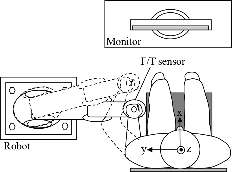
We defined base and local coordinates referring to the method presented in [15]. Fig.1 shows the base coordinate system of the upper limb musculoskeletal model, where the x, y and z axis are defined so as to have forward direction in the sagittal plane, a leftward direction in the frontal plane, and an upwards direction in the sagittal plane, respectively. Fig.2 shows the local coordinates of the scapular thoracic joint (ST), the sternoclavicular joint (SC), the acromioclavicular joint (AC), the glenohumeral joint (GH) and the humeroulnar joint (HU). The details of each local coordinate are shown in Table 1.
2.2. Mechanism of shoulder joint motion
Shoulder motions for flexion/extension, abduction/ adduction and inward/outward rotation are concerned with the three bones comprised by the humerus, the scapular and the clavicle, and the five joints - the scapulohumeral joint, the second shoulder joint, the acromioclavicular joint, sternoclavicular joint and the scapulothoracic joint. Due to the links between the bones, each bone's motion is closely linked with the other bones' motion, which adds extra complexity to the shoulder motions. For example, the motions of the humerus and the scapular are interlocked with each other so that the abduction motion of the humerus causes the scapular to rotate upwards. Since the scapular is floating on the thorax, held in place by small muscles and joints, when it goes up and outside the body trunk, the lower part of the scapular rotates outwardly. Also, the clavicle moves in conjunction with the scapular's motion, but the outer part of the clavicle from body centre (i.e., the extremitas acromialis claviculae side in Fig.2) moves mainly, since the extremitas sternalis claviculae is fixed at the sternum. Therefore, when the scapular rotates upwards, the outer part of the clavicle moves in the upwards direction. Furthermore, when the scapular moves in the forward direction along the rib, the clavicle begins to move in the forwards direction.
The coordinated motion between the humerus and the scapular bones was called the scapulohumeral rhythm by Codman [16]. The coordinated motion was further investigated in [17] [18], where in the “setting phase” of the shoulder motion - which is confined to less than 60 degrees in flexion motion and 30 degrees in abduction motion - Inman et al. insisted that the rotation angles of the glenohumeral and scapulothoracic joints coordinate by a 2:1 ratio. In the setting phase, in order to keep the humerus motion stable, the scapular is prepared by being firmly fastened to the thorax by small muscles.
Base coordinates system

Local coordinate systems of each joint
Local coordinates of each joint


Skeletal structure modelled in the developed model
In 1976, Poppen [19] indicated that the scapular performs a 3 dimensional motion. Using MRI and a magnetic tracking device, it has been clear that during flexing of the humerus, the scapular rotates upward/downward in the forward plane, inward/outward in the horizontal plane and slopes back/front [20–21] in the sagittal plane. In 1991, Hogfors [22] proposed a 3-dimensional Euler angle-based motion function of the shoulder rhythm. However, its accuracy has not yet been fully verified. For the development of reliable rehabilitation motion, therefore, we confined the shoulder angle to less than 60 degrees in its flexion motion and 30 degrees in its abduction motion in this study.
2.3. Upper limb musculoskeletal model
There has been considerable research on the biomechanical analysis of training of the inner muscles and their functional evaluations [23–24]. Kizuka [25–26] investigated the activities of the shoulder muscle based on the analysis of electromyographic signals during the shoulder's adduction/abduction motion and the inward/outward rotation motion from 0 degrees to 120 degrees, respectively. In [25–26], subjects were laid on their backs and the load acting on each subject's shoulder was increased by 2Nm and up to 20Nm using a dynamometer. The activities of the inner shoulder muscles were strong when the load was smaller than 10 Nm, the outward rotation of which the rotation angle was smaller than 45 degrees, the abduction motion of which the rotation angle was smaller than 30 degrees. These results show that when the motion angle is smaller and when the load is lower in both the outward rotation and the abduction of the shoulder, the inner shoulder muscles are well-trained.
Therefore, in this study, we first determine the shoulder motion range in which the scapular can be assumed to be stationary. By developing the shoulder rehabilitation motion in consideration of the scapular's stationery motion range, we can reduce the uncertainty for the identification of the scapular's motion. We developed an upper limb musculoskeletal model shown in Fig.3, where the shoulder has 3 degrees of freedom (DoF), the elbow has 1 DoF and wrist has no DoF.
Fig.4 shows the muscles modelled in the developed upper limb musculoskeletal model. Table 2 shows the origins, insertion points of the muscles and the physiological cross-section area (PCSA) [27]. Table 3 describes each muscle's function. The geometrical structure of each muscle is numerically modelled to have straight line links which connect the attachment points listed in Table 2. For the accurate calculation of the moment arm of an enormous muscle, such as the deltoideus, we considered more than one attachment point. By using the integrated muscle-skeleton model of the patient's body, we can apply a bio-mechanical analysis to the rehabilitation motion. Fig.5 shows the relationship between the moment arm ri,k of the k-thmuscle around i-th joint and the insertion. Based on the geometric relations between the joint position and the relative position, we can calculate the moment arm r i,k by the following expression:
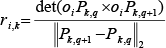
Here, a 2-norm operator was used in the denominator of (1) to obtain the length of two insertion points Pk,q and Pk,q+1.

Muscles modelled in the developed model
Insertion point(s) of each muscle

Function of each muscle

In this study, we referred to Hill's muscle model for evaluating muscle contraction dynamics [28]. The mass and inertia moment for each body segment was estimated for a standard human body shown in [29], where each link of the body model is assumed to be rigid. The relationship between the joint torque and the muscle forces is described in the following equation:
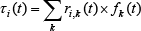
where τ i (t) is the torque at the joint i, f k (t) is the muscle force generated by the muscle k, ri,k(t) is the minimum distance from the rotation axis of the i-th joint to the segmentalized k-th muscle model.
We calculate the muscular force by minimizing the evaluating function u(f(t)), as follows [30]:


Moment arm
Here, PCSA k is the physiological cross-sectional area of the k muscle, and f(t)=[f1(t), …, f k (t)]. By minimizing (3), the minimized muscle fatigue is achieved [26]. During the joint's rotation, the muscle force f k has an upper bound f kmax and a lower bound f kmin , as follows:

3. Simultaneous design of the joint trajectories and external forces
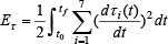
In Fig.1, the device image of the proposed rehabilitation method is shown with the coordinate system. The robot manipulator provides the designed force/moment and the CRT monitor displays the designed motion trajectory and the designed force. A force/torque sensor is attached between the robot end-effector and the attachment of the user. The subject is asked to move his arm in accordance with the motion trajectory and the external force. It may be that the patient cannot achieve the displayed trajectory and force because the generated force between the patient and the manipulator depends on the patient's motor control ability. If the patient cannot follow the trajectory and the force, the robot system leads the user to a closer motion trajectory than the designed one by relaxing the force level. The relaxation will continue until the motion trajectory and the generated force achieve the designed levels.
In this section, a simultaneous design method for the joint trajectories and external forces will be introduced.
3.1. Design of the joint trajectories for the rehabilitation motion
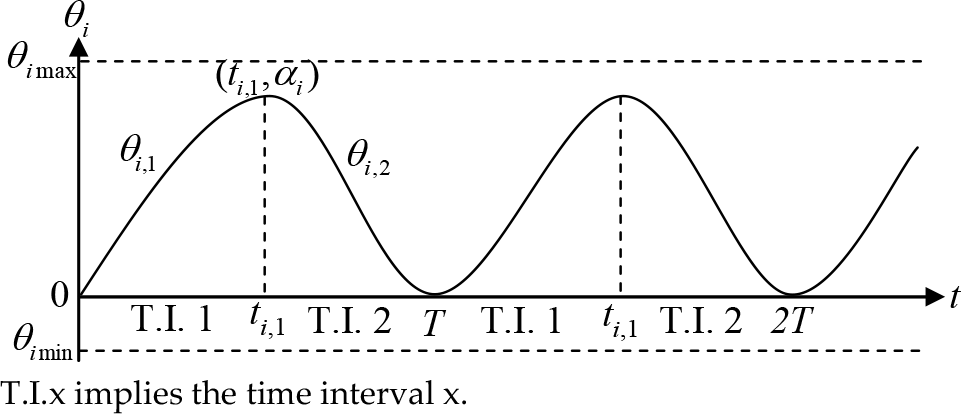
For easy-to-use and stable robot-aided rehabilitation motion, each joint angle θ i (t) should be smooth and cyclic. Each joint angle was constrained in this study so as to be between its upper bound θ imax and its lower bound θ imin . The rehabilitation cycle T is composed of the following two time intervals. The first time interval includes the time 0 ≤ t ≤ t i,1 , where the joint angle θ i increases from θ imin to θimax. The second time interval is for t i,1 ≤ t ≤ T, where the joint angle θ i decreases from θ imax to θ imin .
The joint angle of each section is represented by a fifth-order polynomial function, as follows:

where i is the number of the joint as shown in Fig.1, j is the time section (j =1 or 2), T is the period of the cyclic joint motion and h is the iteration number of the cycle. α i is the angle of i-th joint at t = ti,1, as in Fig.6, and is constrained by (6) and (7):


Since each muscle has a maximum contractile velocity, this constraint can be represented as follows:

The joint angle increases during the first time interval (0 ≤ t ≤ ti,1) and begins to decrease from the beginning of the second time interval (ti,1≤ t ≤ T). A smooth motion between two consecutive time intervals can be achieved by imposing the following constraints at the beginning of each new section.
At t = 0,

At t = ti1

At t = T,
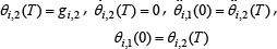
The simultaneous Equations (5) and (10–12) yield (13–22), as follows.


Motion parameters
Under these conditions, the problem considered in this study is transformed into a search problem of α i , T, ti,1, di,1 and di,2 which maximizes the performance function, as we shall see in Section 4.
3.2. Design of the external force in robot-aided rehabilitation
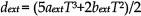
In spherical polar coordinates, the external force acting on the end-effecter (i.e., the patient's hand) can be represented by F ext (t), β(t), γ(t), where β(t) is the angle between the external force and the z axis and γ(t) is the angle between the projection of the external force in the x-y plane of the external force and the z axis. Since the external force F ext (t) should be a smooth periodic function, as shown in Fig.7, we used a fifth-order polynomial function as follows:

In a similar way to the design of the rehabilitation motion trajectory, we have to search 7 parameters, namely a ext , b ext , c ext , d ext , e ext , g ext and T. Since T is calculated from (5), to smooth the external force trajectory we set following constraints:
At t = T

Simultaneous equations of (23) and (24) yield as follows.


Therefore, the external force design problem is transformed into the search problem of a ext , b ext and g ext . We can design β(t) and γ(t) in a similar way by introducing fifth-order polynomial functions.
4. GA-based parameter search for rehabilitation task design
4.1. Evaluate function
In this section, we search the preliminarily structured parameters of the rehabilitation motion and external force trajectories. Taking into consideration kinematics and dynamics, we introduce two performance criteria for the minimization of jerk and the joint torque change rate. The jerk and joint torque change rate during the execution of robot-aided rehabilitation motion are important performance criteria and their minimization leads to a smooth joint trajectory.
They are expressed in the following way:


External force parameters
For biomechanically safe and efficient robot-aided rehabilitation, the appropriate direction of the external force and a magnitude that yields a maximization of muscle force generation and a minimization of loading on each joint's passive elements (such as the ligaments and tendons) must be designed. Muscle loading can be evaluated with the integral of the generated muscle forces generated over the training time, as follows:

In (30), with n=∞, we can evaluate the maximum muscle force. However, in this research, we set n=1 in order to evaluate the recovery of the control function of the small inner muscle force rather than maximize the large muscle's generated force.
For the design of the motion and the external force applied at the hand, we use the evaluation function of (31), which obtains the weighted sum of the three indices. The first index (E f ) maximizes the muscle force, and the latter two indices (E θ and E τ ) minimize the jerk and torque change in each joint. The function E is given by the following equation:

In order to obtain the parameters k1 and k2, we used a trial-and-error method, as follows: we first obtain the absolute value of each term by a preliminary simulation, and then decide upon the weight coefficients by making the sum of the absolute values of the latter terms equivalent to the absolute value of the first term. Therefore, the simultaneous design problem of the motion trajectory and external force trajectories can be transformed into a parameter search problem of di,1, di,2, ti,1 and α i , T for the motion trajectory, and a ext , b ext , c ext , a β , b β , c β , a γ , b γ and c γ for the external force trajectory, which maximize the function (31).
4.2. GA-based rehabilitation motion design algorithm
We demonstrate a GA-based rehabilitation motion trajectory and an external force design algorithm in this section, as follows.
Step1: The trajectory of the joint angle θ i (t) (i=1,2,3) is represented by the motion trajectory parameters d i,1 , d i,2 , t i,1 , α i and T, and the trajectory of the external force that can be defined by F ext (t), β(t), γ(t) is represented by the external force parameters a ext , b ext , g ext , a β , b β , g β , a γ , b γ and g γ . The list of these parameters and the set of each parameter is defined as a gene.
Step2: Define the number of individual genes as P and generate P individuals.
Step3: Based on the inverse dynamics, calculate the joint torque, τ(t), the muscle force, f k (t) and the shoulder joint reaction force, F s (t) of each individual, and evaluate them with the function of (31).
Step4: Generate new individuals by crossover and mutation. The crossover rate and the mutation rate are set to 0.25 and 0.01 respectively. Calculate the evaluation values of the new individuals.
Step5: List all individuals in ascending order of the evaluate values and select P individuals whose evaluation values are higher than the others, and define it as a new generation.
Step6: Repeat step3 to step5 until the variation of the evaluation values remains sufficiently small for 5 consecutive generations.
5. Example
In this section, we give a design example for inner shoulder muscle rehabilitation which is obtained by the proposed design method for the rehabilitation motion and external force trajectories. The parameters that describe the motion and external force trajectories were explored based on the algorithm presented in the previous section. In order to verify the usefulness of the proposed method, we compare the rehabilitation effects of two proposed rehabilitation methods: a weight-based rehabilitation method and a robot-aided rehabilitation method.
Rehabilitation image of the use of the weight
5.1. Simulated conditions
For the rehabilitation of the inner muscles around the shoulder joint, an inward/outward rotation motion and an abduction/adduction motion are all known to be efficient. For the efficient realization of the shoulder's inward/outward rotation and abduction/adduction motion in a robot-based rehabilitation environment, the elbow and wrist joints should be fixed. In this simulation, therefore, the elbow joint was fixed to 90[deg] and the palmar flexion/extension, pronation/supination, radial flexion/extension of the wrist joint were fixed to 0[deg], respectively. The initial conditions for θ1, θ2, θ3 are all 0 degrees. The constraint conditions in the parameter search problem are shown in Table 4.
Calculated results (using a weight)
Constraint conditions

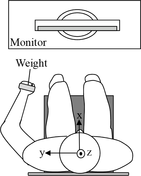
We have designed, here, two inner shoulder muscle rehabilitation exercises based on a biomechanical analysis of the rehabilitation motion. One was the proposed method and the other was partly based upon the proposed method but the external force was set as a constant. We call the latter case ‘weight-based rehabilitation'. In this case, the patient tracks the designed motion trajectory, holding up a weight of 2 kilograms in the hand. The joint motion trajectories are designed with the method introduced in section 3.1, and the constraint conditions in Table 4 are used, except for the constraint of the external force acting on the hand. The design process in this case omitted the optimization procedure on the external force. That is, the external force is gravity of the weight that is simply set as the constant force of the minus z-direction. Fig.8 displays an image of the device setup in the case of the weight-based method. The designed motion trajectory is shown on the monitor. The subject is asked to actively move his arm in accordance with the displayed motion trajectory.
The second method is that of robot-aided rehabilitation, where we use a 6-axis external forces generated by a robot and a 3-dimensional motion. In this case, we calculated the motion trajectory and the external force by using the full process of the optimization procedure described in section 3 and section 4.
5.2. Calculated results for the rehabilitation motion and the force trajectories
We first show the calculated results of the weight-based rehabilitation motion in Fig.9. The trajectories of each joint angle, angular velocity and angular acceleration are shown in Fig.9-(a), 9-(b) and 9-(c), respectively. The designed trajectories of the joint angle vary smoothly within the bounds and satisfy all the constraint conditions. The external force that is acting on the hand and the inner muscle forces are shown in Fig.9-(d), 9-(e). Fig.10 (a) shows a 3-dimensional trajectory of the upper limb and the external force. The designed motion trajectory forms a smooth closed curve. In the shoulder base coordinate (x-y-z coordinate) of Fig.10, the shoulder joint trajectory is flexing, abducting and outwardly rotating simultaneously. In Fig.10, positive values of θ1, θ2, θ3 imply extension, abduction and outward rotation, respectively.
Fig.10-(a) and 10-(b) show the flexion/extension motion in the x-z plane and the abduction, outward rotation motion in the x-y plane of the shoulder. The moving distance of the wrist joint in the x direction in Fig.10 is only 8cm while the moving distances in the y and z directions are 20cm each. This is because the inner muscles mainly generate muscle force during inward/outward rotation and abduction /adduction - that is, the y and z axis rotation direction motion yields inner shoulder muscles to generate muscle force. During abduction motion, the infraspinatus muscle generates a strong muscle force.
At the initial stage of the motion, the palmar side is directed in the negative direction of the y axis and the elbow joint is flexed to 90[deg]. The external force by the weight acts in the direction of gravity, which generates adduction torque and simultaneously helps the supraspinatus muscle to generate strong muscle force for the abduction motion.
In Fig.10-(c) and 10-(d), the designed weight-based rehabilitation motion is combined with the extension, adduction and inward rotation motion of shoulder. Gravity generates adduction torque in the shoulder, which helps the supraspinatus muscle to easily generate muscle force and perform the accurate tracking of the predefined motion and velocity trajectories. Note that in the shoulder motion of Fig.10-(a)(b), the inner shoulder muscles - such as the supraspinatus and the deltoid middle, which contract in abduction motion - are performing concentric training, while in the shoulder motion of Fig.10-(c)(d), those shoulder muscles are performing eccentric training.
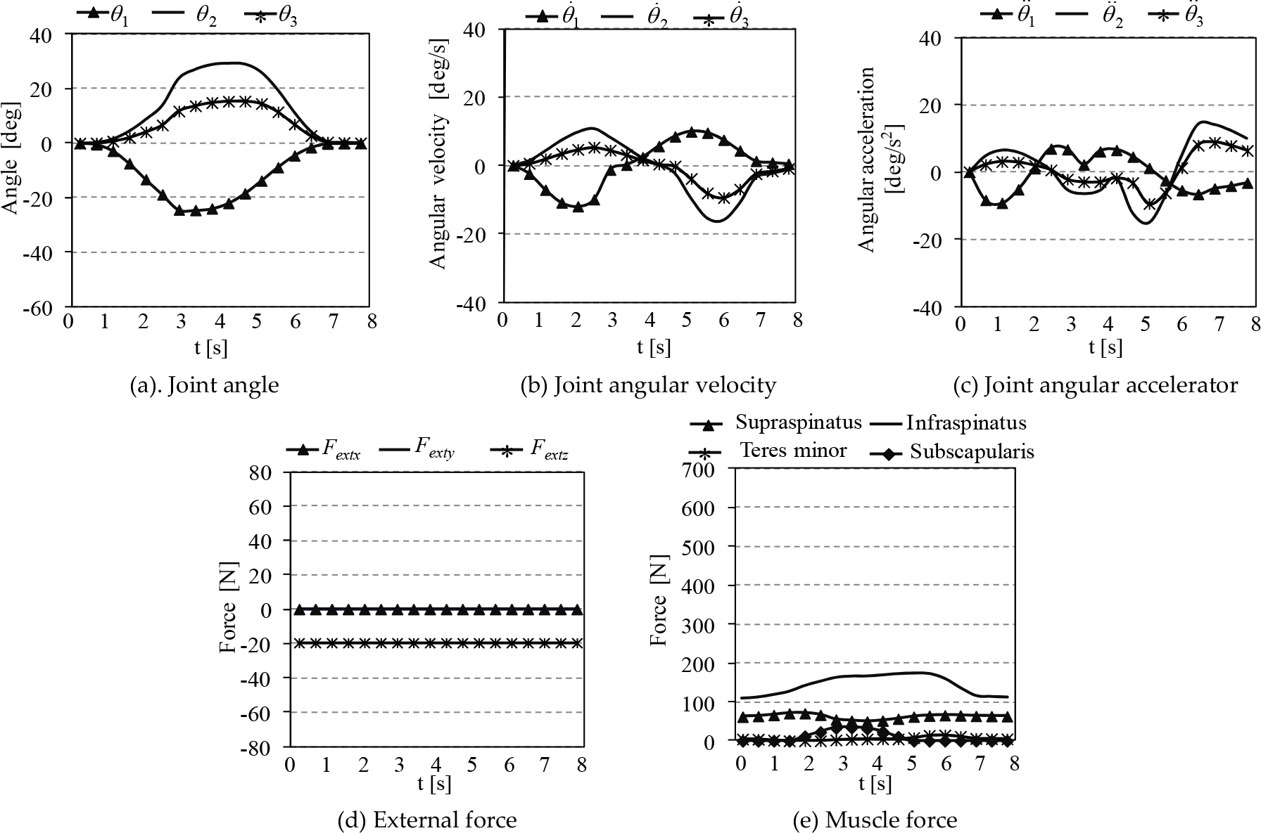
We show the computational results of the robot-aided rehabilitation motion in Fig.11. The trajectories of each joint angle, angular velocity and angular acceleration are shown in Fig.11-(a), 11-(b) and 11-(c), respectively. The external force that is acting on the contact point to the robot and the inner muscle forces are shown in Fig.11-(d) and 11-(e), respectively. Fig.12-(a) shows a 3-dimensional trajectory of upper limb and external force. The designed motion trajectory forms a smooth closed curve. In Fig.12, the designed robot-aided rehabilitation motion is combined with the flexion, abduction and inward rotation motion of the shoulder.
The external force in the direction of the positive x axis assists the shoulder to flex. The external force in the direction of the negative y axis generates adduction torque in the shoulder joint, which helps the supraspinatus muscle to generate a strong muscle force for abduction motion. In this period, the supraspinatus muscle is doing concentric training. On the other hand, the external force in the direction of the positive z axis generates the abduction motion, which helps the subscapularis muscle to easily generate the muscle force for the adduction motion. During this period, the subscapularis muscle performs concentric training.

Weight-based rehabilitation motion and external force trajectories

Calculate results (using robot)
The designed robot-aided rehabilitation motion in Fig.12-(c) and 12-(d) shows a combination of the extension, adduction and outward rotation motion of the shoulder. With the extension motion, the external force in the x axis direction approaches 0 and the action of gravity helps the shoulder to easily extend. In the adduction motion, the external force in the negative direction of the y axis generates adduction torque, which assists shoulder to adduct, while the supraspinatus muscle is kept stretching. During this period, the supraspinatus muscle is doing eccentric training. In the outward rotation motion, the infraspinatus muscle and the teres minor muscle contract to generate muscle forces, which helps the shoulder to easily rotate in the outward direction. The external force in the positive direction of the z axis generates abduction torque, which helps the subscapularis muscle to easily generate muscle force while the subscapularis muscle is kept stretching. During this period, the subscapularis muscle is doing eccentric training.
5.3. Comparison of weight-based and robot-aided rehabilitation methods
In order to show usefulness of the proposed methods, we compared the calculated results in Table 5 by applying the weight-based and robot-aided rehabilitation methods. In the designed robot-aided rehabilitation motion trajectory, the motion ranges of the flexion/extension angle θ1 and the inward/outward rotation angle θ3 were 1.00 and 2.27 times, respectively, larger in the robot-aided rehabilitation motion trajectory than in the designed weight-based rehabilitation motion trajectory. However, the motion range of the abduction/adduction angle θ2 was 50.8% smaller in the robot-aided rehabilitation motion trajectory than in the designed weight-based rehabilitation motion trajectory. The maximum muscle force and the ratio of each inner muscle's generated force per training session were much bigger in the robot-aided method than in the weight-based method. Therefore, the ratio of all the inner muscles' generated force per training session with the robot-aided method was more than three times bigger than the total generated muscle forces in the weight-based method. In the weight-based method, the supraspinatus was trained by generating muscle force through abduction motion using a large motion range for θ2, and the infraspinatus was trained by generating muscle force through an outward rotation motion using a small motion range for θ3 because the infraspinatus has large PCSAs. On the other hand, the teres minor and the subscapularis - which are performing concentric contraction from a musculoskeletal viewpoint through the outward rotation and inward rotation of θ3 - exercised only very small muscle forces since they have a small PCSA. With the robot-aided method, however, all the inner muscles generated large muscle forces because of the efficient design of the external force. Furthermore, as shown in Table 5, the rehabilitation efficiency in the robot-aided method was 31.0%, while that in the weight-based method was 27.7%. This result shows the superiority of the robot-aided rehabilitation method.

External force and motion trajectory of hand (using robot)
Comparison of the robot-aided and weight-based rehabilitation methods
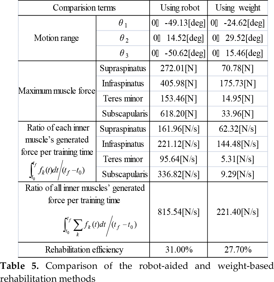

For this computational experiment, we obtained the rehabilitation efficiency as follows:

where η is the efficiency of the rehabilitation motion, E m is the energy generated by the targeted inner shoulder muscles in this study and E A is the mechanically consumed energy at each joint of the rigid human body model for t0 ≤ t ≤ t f .
The reason why robot-aided method has a greater rehabilitation effect might be considered as follows: the external force was designed to make the inner muscles generate larger forces. With the flexion/extension motion, the rehabilitation motion in robot-aided method has a larger shoulder joint motion range than in the weight-based method. The shoulder flexion/extension motion has little relation to the inner shoulder muscle's force generation from the viewpoint of the musculoskeletal structure. Therefore, the shoulder flexion/extension motion that accompanies the large joint motion range lowers rehabilitation efficiency. However, the external force in the direction of the positive x axis that was designed in this study helps the shoulder joint to flex, which leads to a high rehabilitation efficiency.
6. Conclusions
In this paper, we have proposed new simultaneous design methods of motion and external force trajectories for the rehabilitation of the shoulder's inner muscles: a 3-dimensional weight-based rehabilitation method and a 3-dimensional robot-aided rehabilitation method. We first developed a 3D musculoskeletal model of 4 bones and 19 muscles around the shoulder joint and the upper limb. The motional DoF of the shoulder joint was limited to 3 for flexion/extension, abduction/adduction and outward/inward rotation, which is smaller than the actual motional DoF. The model was used for the calculation of those motions and external forces of the robot that cause each joint motion and muscle force as needed for the rehabilitation process. Each joint motion and external force trajectory that was designed for inner shoulder muscle rehabilitation can be readily adapted to the patient's characteristics because the method proposed in this paper is a model-based approach and allows the alteration of the parameters of the musculoskeletal model. In the developed rehabilitation motion, each joint angle and external force changes smoothly within its bounds. The parameters of the rehabilitation motion trajectory and the external force trajectory generated by the robot are for searched by the proposed Genetic Algorithm.
In order to verify the usefulness of the proposed rehabilitation method, we compare the robot-aided and weight-based rehabilitation methods. The robot-aided rehabilitation method generated larger muscle forces for the inner muscles around the shoulder joint and showed greater rehabilitation efficiency. The weight-based method shows only the effect of the optimization on motion trajectories; on the other hand, the proposed robot-based method shows the effect of the optimization on both the motion trajectories and external forces. The weight-based method may be practical from a cost effectiveness point of view; on the one hand, the robot-based method is more desirable from an exercise efficiency and safety point of view.
Traditionally, the shoulder's inward/outward rotation and abduction/adduction motion have been considered efficient for the rehabilitation of the inner shoulder muscle. In contrast, the results obtained in this study show that by appropriately designing the external force provided by robot, we have developed higher rehabilitation efficiency and safer rehabilitation exercise by using the wider extension/flexion motion range and the smaller abduction/adduction motion range.