
Abstract
The electric plunger hydraulic pump plays a crucial role in hydraulic transmission technology by integrating an electric motor and a hydraulic pump. The main objectives in designing such devices are to improve efficiency, achieve miniaturization, and promote environmental sustainability. This paper introduces a speed control strategy for an electric hydraulic pump that operates across its entire speed range without relying on position sensor feedback. We begin by establishing the overall model of the electric hydraulic pump and motor characteristics under different operating conditions. Next, we employ a high-frequency injection control method to enable the electric hydraulic pump to start at zero-speed or low-speed states. Additionally, the optimized extended Kalman filtering control method enhances the robustness and tracking performance of the electric hydraulic pump in the medium to high-speed range. Finally, considering the motor characteristics under different operating conditions, we achieve sensorless control of the electric hydraulic pump across the full speed range. Our proposed control strategy provides a promising solution for the control of electric plunger hydraulic pumps, with widespread industrial applications.
Keywords
Introduction
The Permanent Magnet Synchronous Motor (PMSM), with its outstanding power density, efficient operational characteristics, and excellent control performance, has found extensive applications in academic fields such as rail transportation, aerospace, and servo control.1,2 Its high power density is manifested by achieving a significantly higher power output in a relatively small volume and mass, which is crucial for applications with strict requirements on system weight and size. Simultaneously, its exceptional operational efficiency contributes to reducing energy losses, enhancing energy utilization efficiency, and has now been widely employed as a power source in long-duration electric vehicles, aircraft, and other systems, providing efficient and controllable driving force for various applications.
Benefiting from the expanding applications of PMSM, the rapid development in various fields demands superior control performance from PMSM control systems. Within the full speed and torque range, precise control performance, higher system stability, faster dynamic response, minimal fluctuations, and good adaptability to parameter uncertainties are required.3,4 These impose higher challenges and requirements on the control strategies for PMSMs.
To ensure high-performance operation of PMSMs, vector control is commonly employed, necessitating accurate acquisition of the motor rotor position information.5,6 Position sensors are typically installed at the motor shaft end, requiring a low-voltage power supply from an external control system. However, position sensors increase the motor volume, severely limiting the application of PMSMs in high-power density environments. Additionally, the external control circuit needed for processing the output signals from the position sensor increases the cost of the motor system, diminishing its market competitiveness. In extreme environments, such as strong electromagnetic fields, high temperature, high humidity, and high salinity, there is a risk of failure in position sensors and their processing circuits, impacting the reliability of the motor system. In certain special scenarios, it may be impossible to reserve a location for installing a position sensor.
Currently, PMSM sensorless control systems without position sensors have broad prospects for applications. In the field of hydraulic technology research, the use of electric-hydraulic pump systems centered around PMSMs can expand dynamic control capabilities to various aspects of electro-hydraulics. By controlling the motor, these systems achieve the conversion of electro-hydraulic energy and control of hydraulic actuating components.
The design concept of hydraulic motor pumps first appeared in the early 20th century in the United States. However, due to the material and manufacturing levels at that time, large-scale patent applications and prototype launches of hydraulic motor pumps did not occur until around the 1990s. A prototype of an axial piston hydraulic motor pump was designed and manufactured for experimentation in Reference. 7 Subsequently, the structural design was optimized,8,9 and the internal flow channels and electromagnetic fields were analyzed, modeled, and simulated, providing a theoretical foundation for subsequent optimizations. References 10 studied a motor pump with an integrated fault-tolerant permanent magnet synchronous motor and slanting disc piston pump, establishing a unified mathematical model of a high-speed motor pump and expressing relevant characteristic parameters in harmonic form. This report provided the relationship between static magnetic field parameters of the motor and harmonics. To address the control issues of electric-hydraulic pumps, a permanent magnet synchronous motor was selected to provide the driving force for the entire hydraulic transmission process, achieving the optimization control target.
The sensorless control technology of electric-hydraulic pump systems has profound implications in engineering applications. By eliminating the dependence on traditional position sensors, it reduces system costs, avoids the expenses associated with sensor installation and maintenance, enhances system reliability, eliminates potential failure points introduced by sensors, and makes electric-hydraulic pump systems more stable and reliable.
For the estimation of the rotor position of the motor at zero or low speeds, the commonly employed method is leveraging the salient pole effect of the motor. 11 However, due to the involvement of complex signal processing, this process injects a substantial amount of high-frequency signals into the system,12–15 generating numerous interference harmonic signals. This affects the stability of the stator current, making it unsuitable for prolonged usage. 16 For the speed control requirements of Permanent Magnet Synchronous Motors (PMSM) within the medium to high-speed range, control algorithms based on the fundamental wave back electromotive force or magnetic flux are typically used. 17 These algorithms include methods such as sliding-mode observers and model reference adaptive systems.16,18–21
In overcoming these opportunities and challenges, hydraulic transmission technology is developing toward energy savings, compactness, portability, and cleanliness.11,22 Hydraulic motor pumps integrate the motor and hydraulic pump, conforming to the development trend of improving efficiency, miniaturization, and environmental protection, and are an important branch of hydraulic transmission technology development.
The two-dimensional piston-type hydraulic motor pump is shown in Figure 1, which combines the two-dimensional piston pump with the permanent magnet synchronous motor. Several advantages are offered by this combination, including a simple structure, high efficiency, low noise, and high operating speed of the two-dimensional piston pump. Additionally, it is compact, has a high power density ratio, and exhibits high efficiency as compared to the three-stage structure of the “motor-coupling-pump.” Thus, this structure offers broad application prospects that make it a promising solution for applications with tight restrictions on space, weight, and other aspects.
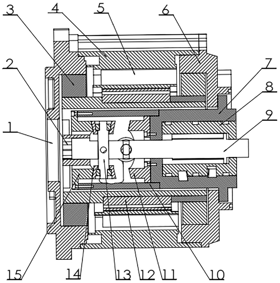
Two-dimensional plunger-type hydraulic motor pump structure drawing.
As shown in Figure 1, the two-dimensional piston hydraulic motor pump combines a two-dimensional piston pump with a permanent magnet synchronous motor. In addition to the advantages of simple structure, high efficiency, low noise, and high operating speed of the two-dimensional piston pump, the electric-hydraulic pump has the advantages of compact structure, high power density ratio, and high efficiency compared with the three-stage structure of the “motor-coupling-pump.” In applications where strict limitations are imposed on space, weight, and other aspects, this design offers broad application prospects.
When energized, three-phase current flows into the three-phase symmetrical windings of the stator of the two-dimensional piston hydraulic motor pump, producing a rotating magnetic field with constant amplitude. The permanent magnets distributed on the rotor interact with the rotating magnetic field of the stator to generate an electromagnetic torque that rotates the rotor relative to the stator of the motor pump. This rotation of the rotor drives the coupling, which transmits the torque to the piston shaft of the two-dimensional piston pump, causing it to rotate. The piston shaft has a fixed roller shaft, and the roller on the roller shaft, constrained by a spatial cam mechanism, performs radial rotation while performing axial reciprocating linear motion, driving the two-dimensional piston pump to work.
Based on the design concept of the two-dimensional piston hydraulic motor pump, this paper investigates the operation of the electric-hydraulic pump with a sensorless full-speed domain optimization control. A control strategy for sensorless full-speed domain optimization based on the electric-hydraulic pump is proposed to achieve the optimization control effect of the electric-hydraulic pump across its entire speed range. Related Work
Basic parameters of the electro-hydraulic pump
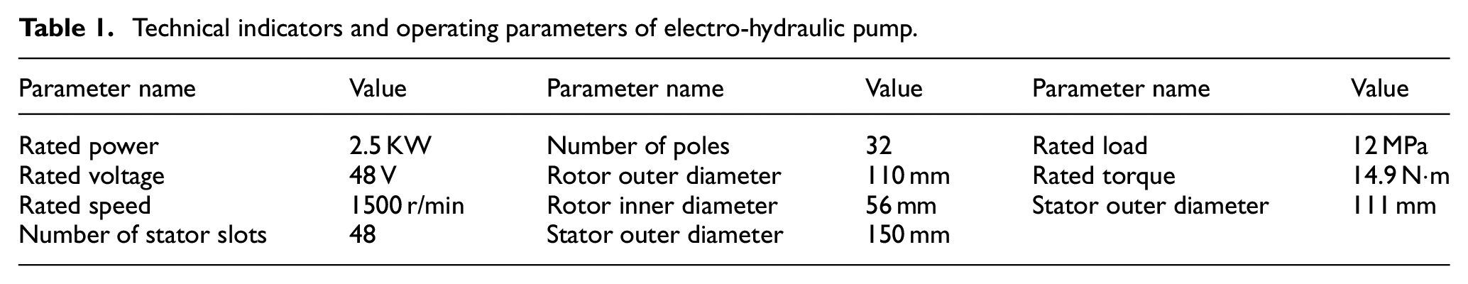
The two-dimensional axial piston hydraulic motor pump is a highly integrated combination of an electric motor and a hydraulic pump. It requires the electric motor to have excellent performance, reliable operation, simple structure, and high power density. The permanent magnet synchronous motor provides excitation through the permanent magnet, eliminating the need for a collector ring and brush and making the structure simple. It does not require an excitation current to excite, reducing losses and improving the motor power density. Its small moment of inertia allows for a large allowable pulse torque, and high acceleration can be achieved with good dynamic performance. Therefore, the permanent magnet synchronous motor is adopted as the form of the motor in the two-dimensional axial piston hydraulic motor pump. The main technical parameters of the two-dimensional axial piston hydraulic motor pump are shown in Table 1.
Technical indicators and operating parameters of electro-hydraulic pump.
Control method
In general, a permanent magnet synchronous motor can be equivalent to a DC motor through coordinate phase transformation, and the control method of an analog DC motor is used to control the nonlinear motor system. Determining the real-time status of the motor and detecting the rotor position angle and real-time status of the motor are important factors for improving the accuracy of orientation and speed regulation. Traditional control methods are mainly divided into position sensor control and sensorless control.
The main difference between sensor and sensorless control is that the former requires sensors to be installed at the position reserved for the motor to capture real-time motor parameter feedback. This feedback is recorded by capturing speed and angle information from the sensor and using real-time motor parameters as inputs to the controller. In contrast, sensorless control does not require sensors installed in sensor control and is based on the observer capturing the readily available instantaneous information required by the algorithm to calculate real-time motor parameter information and predict the next moment’s motor state. The system state is simulated through the prediction step, and the simulated value is compared with the expected value to achieve sensorless control.
As the motor winding is distributed in a three-phase manner, the three phases are defined as the A-phase, B-phase, and C-phase. When the motor is run.3ning, the rotor rotates at a certain angular velocity, and the excitation winding on the rotor generates an excitation current under the influence of the excitation voltage. The axis along the excitation pole is defined as the d-axis, and the axis orthogonal to the d-axis is the q-axis. The d-axis and q-axis are fixed on the rotor, and the d/q-axis rotates synchronously with the rotor during motor operation.
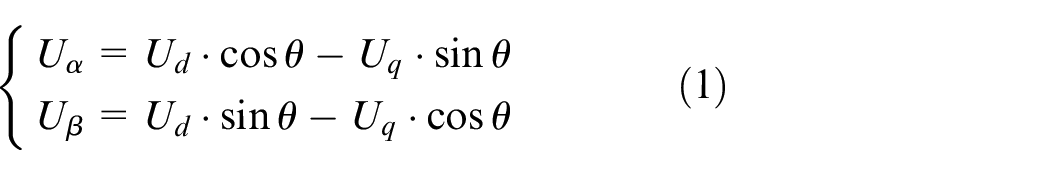
In Formula (1), the coordinate transformation is performed on the two input voltages, and the d-axis q-axis voltage in the rotor coordinate system that follows the rotor rotation is converted to the alpha-axis and beta-axis voltage in the DC coordinate system.
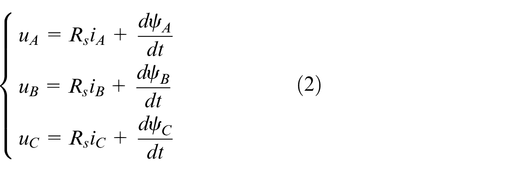
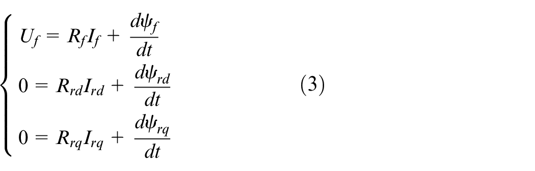
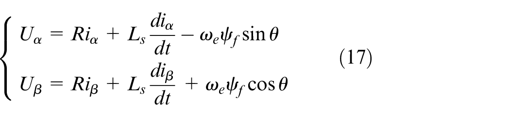
The stator voltage equation of a synchronous motor is written as:
The rotor voltage equation is written as:
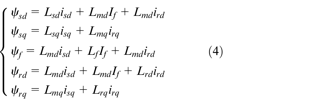
The flux equations in the d-axis and q-axis rotating coordinate systems are written as:
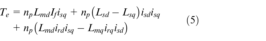
After rearranging the electromagnetic torque equation, it can be written as:
Therefore, the following assumptions are made:
(1) The three-phase windings are symmetrical, and the distribution of the magnetic potential generated during motor operation along the air gap follows a sinusoidal distribution.
(2) We can neglect iron core losses.
(3) We can neglect magnetic saturation of the magnetic circuit.
(4) We can neglect the effect of motor operating frequency and heat generation on winding resistance during operation.
Zero-speed and low-speed startup state
When the system is in a zero-speed or low-speed startup state, a high-frequency injection startup method is used. The control block diagram of the zero-speed or low-speed domain of the electro-hydraulic pump is shown in Figure 2.
Control block diagram of the zero-speed or low-speed domain of the electrohydraulic pump.
The mathematical model in synchronous rotating coordinates is written as:
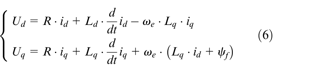
In a simulated circuit, the circuit impedance is composed of the inductive impedance and the resistive impedance. When a high-frequency excitation signal is applied to the circuit, as the frequency of the excitation signal increases, the impedance continues to increase. When the inductive impedance in series with the resistor is much larger than the resistive impedance, this resistive impedance can be neglected. Therefore, the impedance in an AC circuit can be approximated as being determined by the inductive impedance in the circuit.
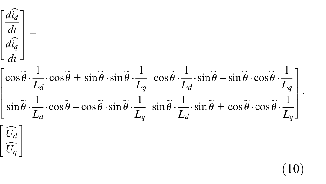
When a high-frequency excitation signal is applied to the d-axis, the inductive impedance in the circuit is much larger than the resistive impedance under the influence of the high-frequency signal. The resistive impedance accounts for a low proportion of the total circuit impedance. Therefore, this resistive impedance can be approximated as zero. Additionally, at zero speed and low-speed starting, the rotor speed in the magnetic field is relatively low, so the simplified mathematical model in the synchronous rotating coordinate system is affected by these factors:
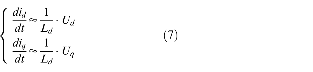
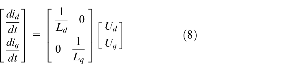
The matrix form of the simplified mathematical model in the synchronous rotating coordinate system is written as:
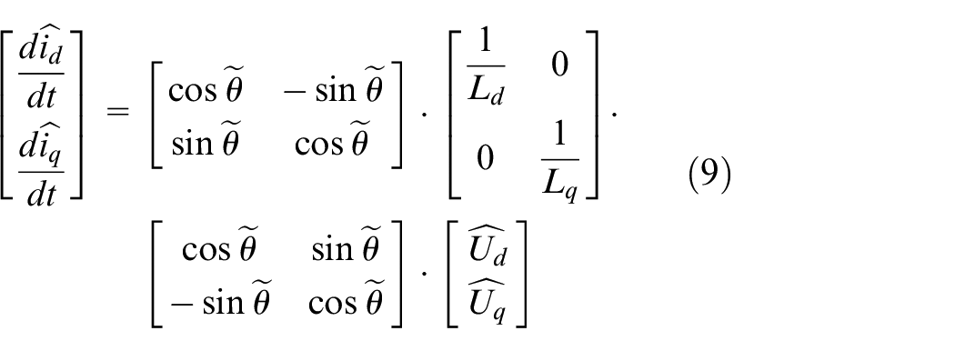
Under the control mode without position sensors, accurately determining the actual angle of the d/q-axis is a key requirement for control accuracy. There exists an angle error between the actual angle of the d/q-axis and the estimated angle of the d/q-axis. The actual rotor position can only be determined when the estimated angle approaches the actual angle and the angle error tends to zero.
The reverse Park transformation of the observed voltage is written as:
The excitation voltage and response current in matrix form are written as:
The expressions for the excitation voltage and response current under the excitation state are written as:
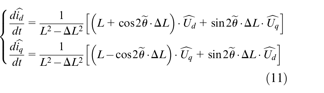
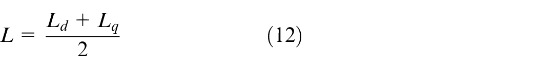
where the average inductance is written as:
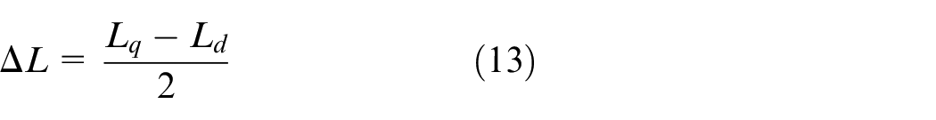
where the differential inductance is written as:
Due to the different physical characteristics of the d-q axis, injecting a high-frequency voltage signal into the d-axis can cause high-frequency vibration and pulsation in the rotor, while injecting a voltage signal into the q-axis only changes the magnetic flux and thus has a smaller impact on the overall system stability. Therefore, injecting a high-frequency voltage signal into the d-axis is chosen.
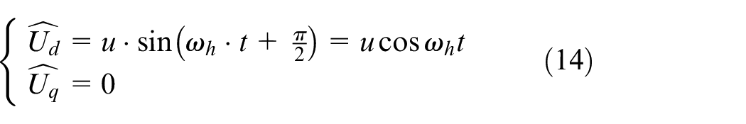
The injected high-frequency sine wave voltage signal is written as:
The expression for the response current after injection is written as:
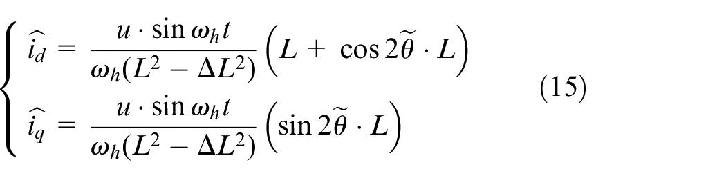
According to the calculated position based on the response current after injecting high-frequency signals, the angle information during motor operation can be obtained. In this method, the physical quantities of the d-axis inductance and the q-axis inductance cannot be equal, but they are still relatively similar in the case of extremely small half-difference inductance. This property can be used to track their inductance errors. Due to the lower interference terms in the estimated q-axis response current in the response expression, the angle calculation is performed on the q-axis response current:
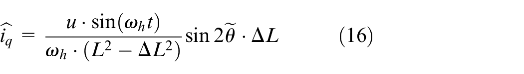
According to the solved position based on the response current after injecting high-frequency signals, the angle information during motor operation can be obtained. In this method, the physical quantities of the d-axis and q-axis inductance cannot be the same, but they are still relatively quantitative under the condition of a very small half-difference inductance, which can be used to track their inductance errors. Due to the fewer interference terms in the q-axis response estimated current in the response expression, the q-axis response current is used for angle calculation.
However, the obtained position information still contains the influence of the high-frequency injected signal, which needs to be converted to the positive-axis variable by coupling with the same-frequency sine signal through a bandpass filter and then separated into fundamental waves and high-frequency signals by a low-pass filter. The angle error can be reduced by adjusting the rotor position error, which enables more accurate position tracking.
Since the harmonic signal converges to zero twice in one period and the phase difference between two zero points is
The high-frequency pulse injection method offers a wide range of applications when the motor operates at zero speed and low speed, and its core is to extract the actual position of the rotor through current feedback. The information generated by the injection method of the pulse will affect the control effect, and the error in determining the actual rotor angle during information solving causes certain rotor errors. Appropriate control system design methods can effectively reduce the position error of the rotor, provide prior conditions for the actual application of subsequent algorithms, and enable the system to quickly generate a more suitable electromotive force for observation.
Medium- and high-speed operating states
When the system is in medium- and high-speed operation states, the state observer algorithm uses the extended Kalman filter algorithm. The control block diagram of the medium-speed or high-speed domain of the electro-hydraulic pump is shown in Figure 3.
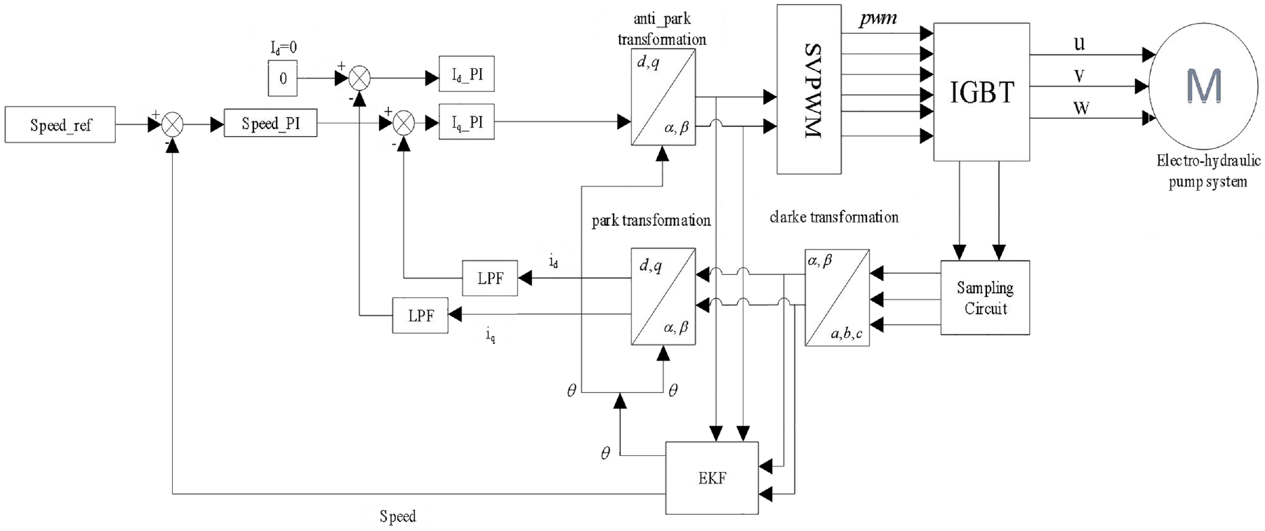
Control block diagram of the medium-speed or high-speed domain of the electrohydraulic pump.
The Kalman filter algorithm is a recursive linear minimum variance estimation algorithm, but most real systems are nonlinear. Therefore, the extended Kalman filter algorithm is introduced to deal with nonlinear systems, such as electric motor systems. The essence of its control method is to use sensor sampling and analysis of the current in the drive circuit based on the statistical characteristics of the system to achieve prediction of the next moment of the system and correction based on its time-varying characteristics and current feedback, thereby improving the control tracking accuracy. Unlike other state observers, such as the Runge-Kutta observer and the sliding mode observer, which rely on the Lyapunov stability criterion, the extended Kalman filter observer offers good low-speed performance based on its use of statistical characteristics.
The mathematical model of the permanent magnet synchronous motor is written as:
This model is reconfigured to obtain:

In the equivalent mathematical model of the permanent magnet synchronous motor, the three-phase resistance, inductance and the corresponding counter electromotive force are the inherent parameters of the motor, which are easily affected by the ambient temperature during the operation of the motor, and its anti-interference is weak, so it is necessary to introduce the state. The observer reconstructs the state of the system, realizes the closed-loop control of the angle, and improves the following ability of the system in the control process.
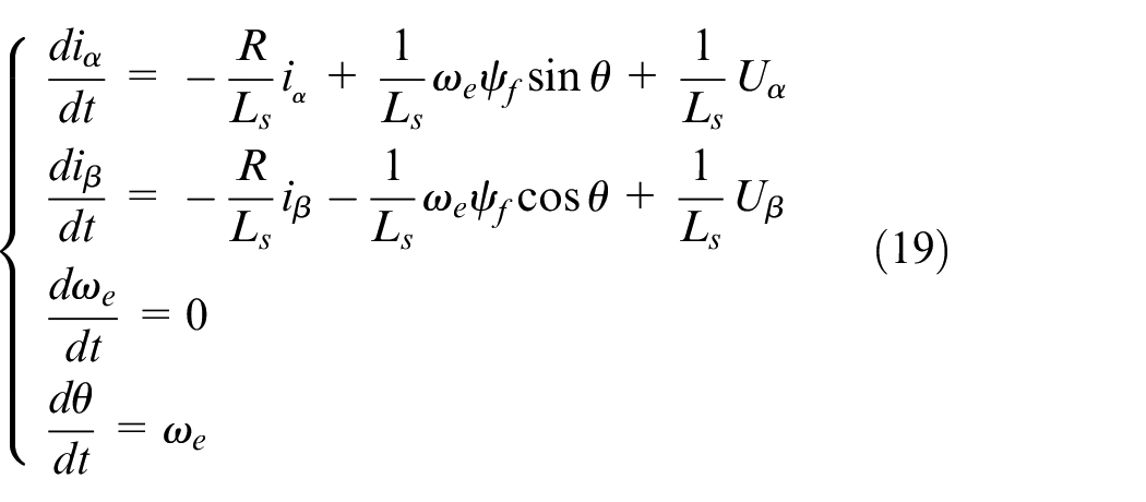
We then convert the motor mathematical model to a state-space expression:
After the voltage after inverse Park transformation is input into the motor system, since the state observer is introduced into the control system, the motor system is reconstructed in the controller according to the response current in the real system, and the position sensorless algorithm is used according to the observed. The observation angle and observation speed of the rotor are calculated by responding to the current, and the observation information calculated by the system and the actual system input information are continuously iteratively processed to realize accurate control of the overall system without position sensing.
The algorithm steps are mainly as follows:
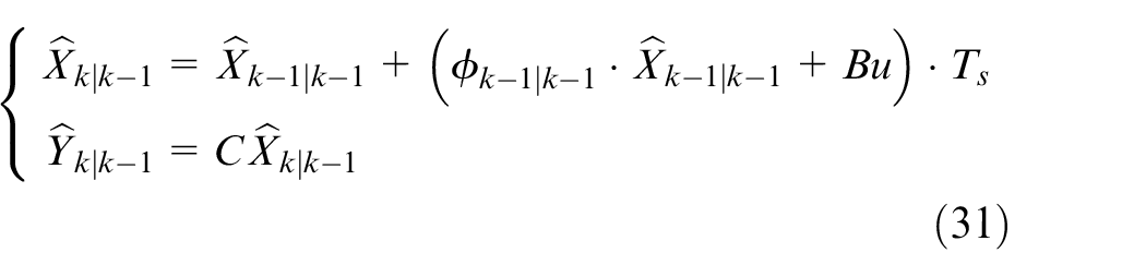
① Establish the state observer prediction equation:
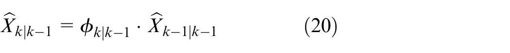
The nonlinear system has an uncertain input and output relationship. The extended Kalman filter algorithm depends on the system characteristics, and based on the Gaussian distribution, the prediction of the current state variables to the next state variables is established. There may be systematic deviations between the state variables predicted by the prediction equation and the actual system state variables. where
② Calculate the forecast covariance:
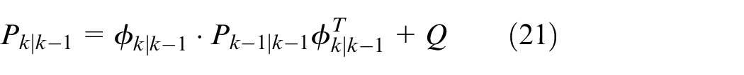
The covariance matrix associates the multistate variables in the nonlinear system matrix and predicts the covariance matrix of the next state based on the system error at the current moment and the error noise generated in the process, that is, it completes the prior of the error covariance of the next state. where
③ Calculate Kalman gain:
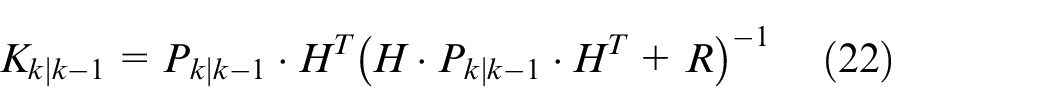
In execution of the extended Kalman filter algorithm, the Kalman gain associates the actual state value and the calculated estimated value through the Kalman gain, where
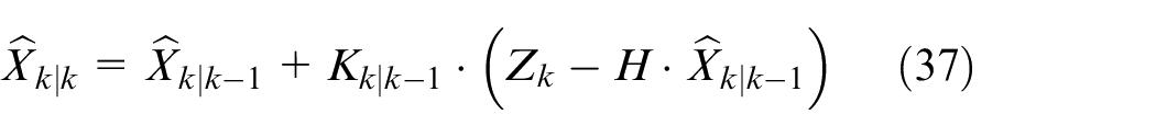
④ Correct the estimated value:
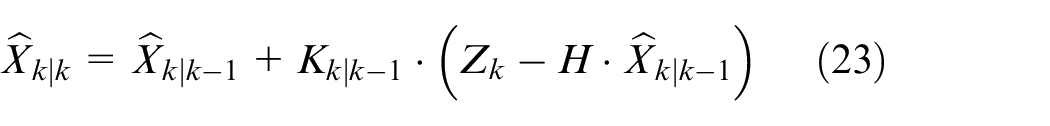
According to the calculated Kalman gain, the predicted current state is corrected and updated to obtain the posterior estimated state variable of the current state.
⑤ Calculate the estimated covariance at the next moment:

To subsequently estimate the system state quantity, update the covariance matrix of the estimated and actual system error, and complete the preparation of the parameters required for estimating the next state during the algorithm iteration process.
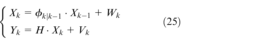
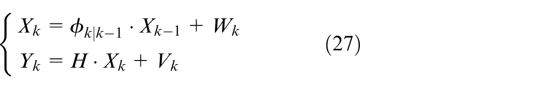
The system state equation and measurement equation can be expressed as:
The advantages of the extended Kalman algorithm are as follows:
① Approximate the nonlinear system as a linear system.
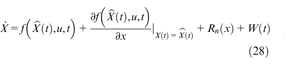
This approximation can be obtained by Taylor expansion:
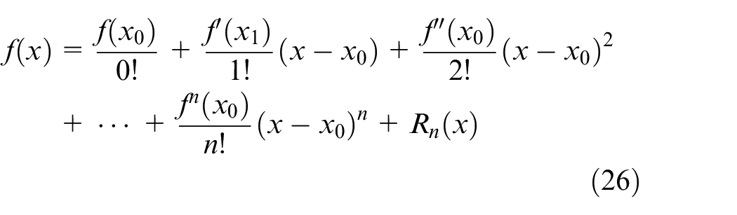
The Extended Kalman Filter algorithm serves as an advanced method specifically designed for state estimation in nonlinear systems. In the realm of motor control, the complexity of motor behavior often manifests as nonlinear characteristics in its dynamic models, thus necessitating the widespread application of the algorithm. The core principle of this algorithm lies in the utilization of Taylor series expansion to approximate the original nonlinear system model as a linear one near a specific operating point. By doing so, the standard Kalman filter algorithm can be applied, enabling effective state estimation.
The system state equation and measurement equation can be expressed as:
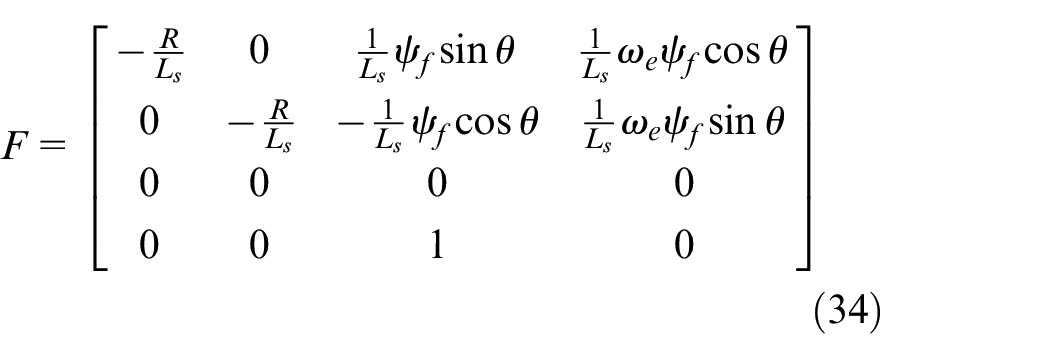
After Taylor expansion of the pair, we obtain:
where
② Transform the continuous system into a discretized system:
Because the data processed by the actual system and the microcomputer system are different, it is necessary to obtain the differential form that can be processed through transformation.
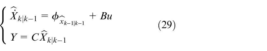
Organized to obtain:
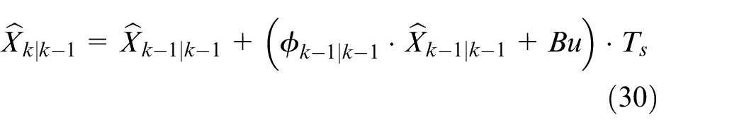
In summary, the algorithm steps are revised as follows:
① Predict the preliminary state estimation:
② Calculate the predicted mean square error:

where

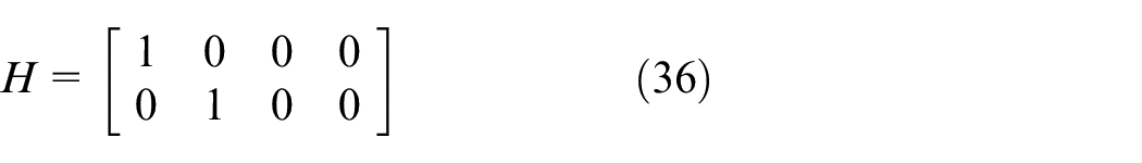
③ Calculate Kalman gain
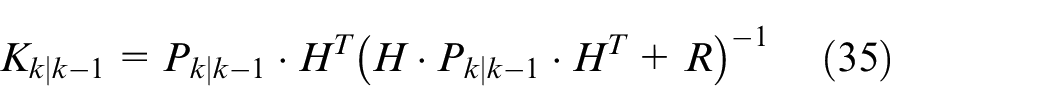
where
④ Correct the prediction through the calculated Kalman gain to obtain the optimal estimate of the current state.
where
⑤ Calculate the covariance matrix used for prediction in the next algorithm execution.

The introduction of the extended Kalman filter as the state observer of the system can approximate the complex nonlinear electro-hydraulic pump operation system as a linear non-Gaussian system near the observed operating point. The modified extended Kalman filter observer construction algorithm can, when the motor is at a medium or high speed state, improve the follow-up performance of the observer system to the real-time system to achieve better dynamic performance.
Simulation and experimental test
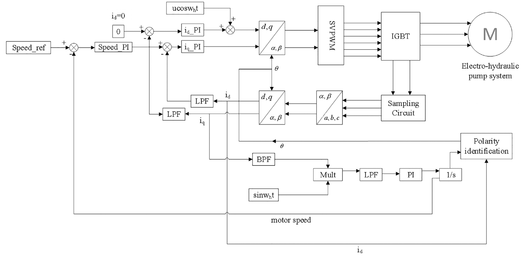
Our control strategy proposed is applied in simulation to test our electro-hydraulic pump system using MATLAB. The overall logic of the control strategy is shown in Figure 4.
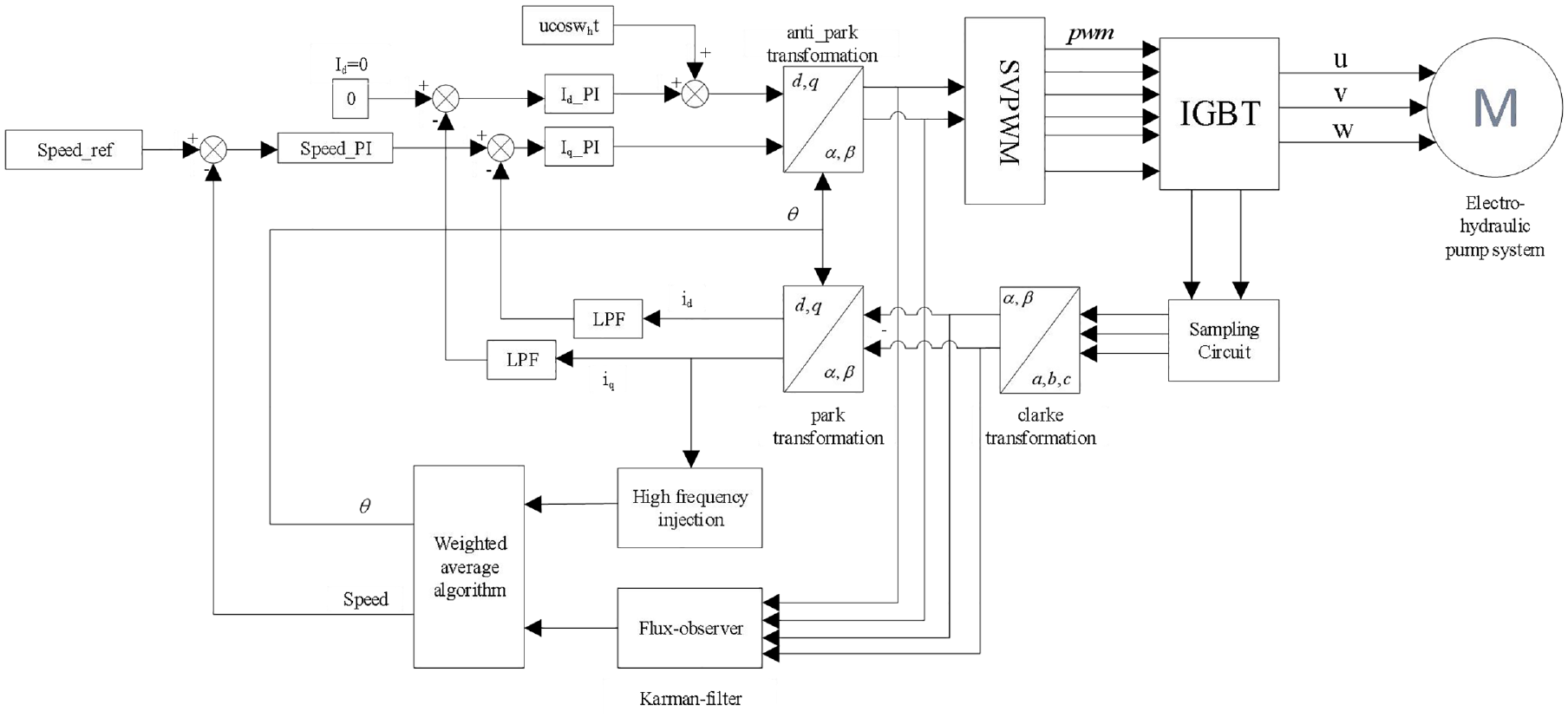
Control block diagram of the full-speed domain of the electro-hydraulic pump.
We conducted a comprehensive validation of the overall algorithm’s applicability from six distinct perspectives. Firstly, a step response was introduced into a no-load system, and the waveform was carefully observed to assess the potential occurrence of overshoot in the control system. Additionally, the speed of the electro-hydraulic pump was tracked in real-time to ensure its alignment with the expected velocity. Secondly, loading tests were performed to evaluate the overall robustness of the control strategy across varying load conditions. Thirdly, once the entire electro-hydraulic pump system achieved stable operation, speed variations were introduced to measure the system’s response time and ensure its compliance with predefined requirements. Fourthly, a comparative analysis with other control algorithms was conducted to underscore the superiority and innovative aspects of the algorithm proposed in this study. Fifthly, variable speed experiments were executed to demonstrate the practical effectiveness of the control algorithm across different operational speeds. Finally, we simulated the loading conditions encountered by the electro-hydraulic pump during actual operation and conducted experimental tests to further corroborate the rationality and practical utility of the algorithm. These rigorous validations ensure the scientific rigor and reliability of our findings, thus contributing to the advancement of electro-hydraulic pump technology.
Step response test
The step response test is carried out on the electro-hydraulic pump system, and the control target is set to 1500 rpm.
Speed
Figure 5 demonstrates the speed waveform of the electro-hydraulic pump. Based on the simulation results, the operating speed of the overall electro-hydraulic pump is capable of reaching the desired target within 0.12 s, and there are no notable signs of overshoot throughout the system. The step response test results indicate that the overall electro-hydraulic pump system possesses a rapid response speed.
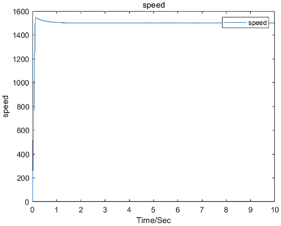
Speed diagram of the electrohydraulic pump during the step test.
Stator current
Figure 6 displays the three-phase current results of the stator of the electro-hydraulic pump. According to the simulation results, the initial current of the overall simulation is relatively high, providing sufficient electromagnetic torque for the overall system control. When the speed reaches the desired level at 0.12 s, the current stabilizes, and the current response reaches a steady state more quickly.
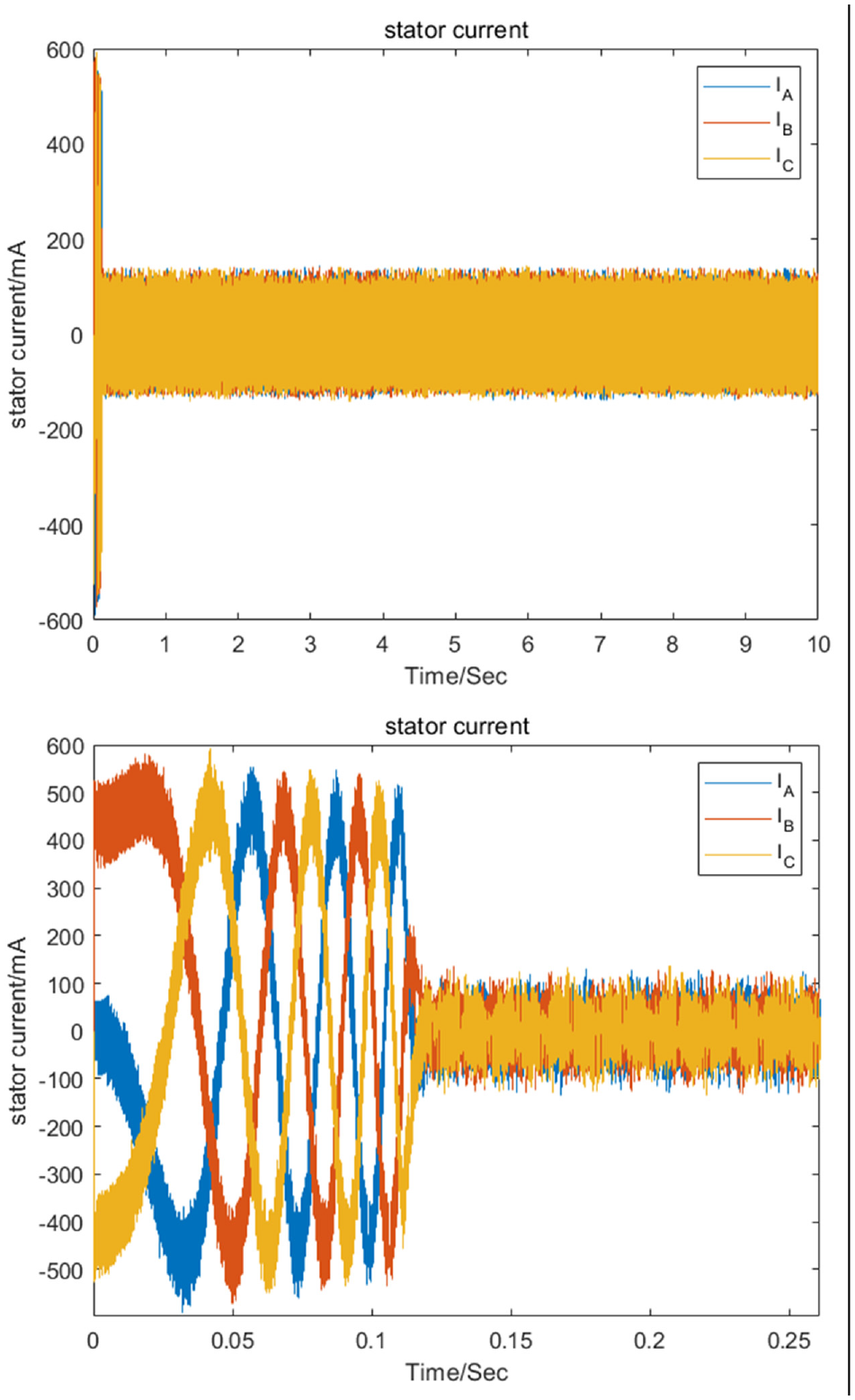
Stator current diagram in the case of the electro-hydraulic pump step test.
Load test
A load test was carried out on the electro-hydraulic pump system. The control target was set to 1500 rpm, the load application time was the third second of the system operation, and the end time was the sixth second of the system operation process.
Speed
Figure 7 is a speed waveform diagram under the load test of the electro-hydraulic pump control strategy. According to the simulation results, the system reaches the desired speed of 1500 rpm at 0.12 s. After reaching the target speed and stabilizing, the load is introduced to the system according to the working conditions of the electro-hydraulic pump. When the system is loaded, it can recover to a stable state in a short period of time of 0.45 s; when the load is stopped, it can recover to a stable state in a short period of time of 0.47 s. The load test results show that the entire electro-hydraulic pump system has good robustness and response speed, and the control strategy meets the test requirements.
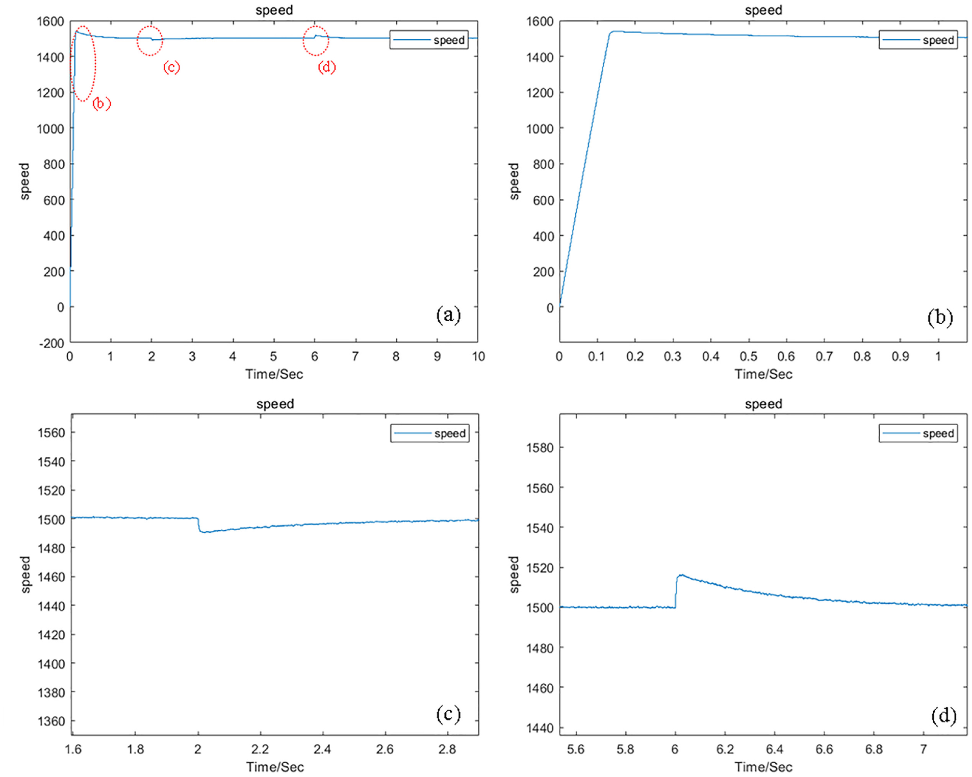
Speed diagram of the electro-hydraulic pump during the load test: (a) shows the overall waveform, while Figure (b), Figure (c), and Figure (d) show the local amplification of the waveform circled in Figure A, which can more intuitively demonstrate the strong following ability of the control strategy.
In Figure 7, Figure (a) shows the overall waveform, while Figure (b), Figure (c), and Figure (d) show the local amplification of the waveform circled in Figure A, which can more intuitively demonstrate the strong following ability of the control strategy.
Stator current
Figure 8 shows the three-phase current results of the electro-hydraulic pump stator. According to the simulation results, the initial current of the overall simulation results is relatively large, providing sufficient electromagnetic torque for the control of the electro-hydraulic pump. When the speed reaches the expected requirement, the current tends to stabilize. After the system stabilizes, when the system is loaded, the stator current increases accordingly. When the system speed returns to the expected set parameter target, the stator current tends to stabilize. When the load is stopped, the current stabilizes before returning to the stable state before the load, and the response time for the current to return to steady state is faster, without significant current fluctuations.
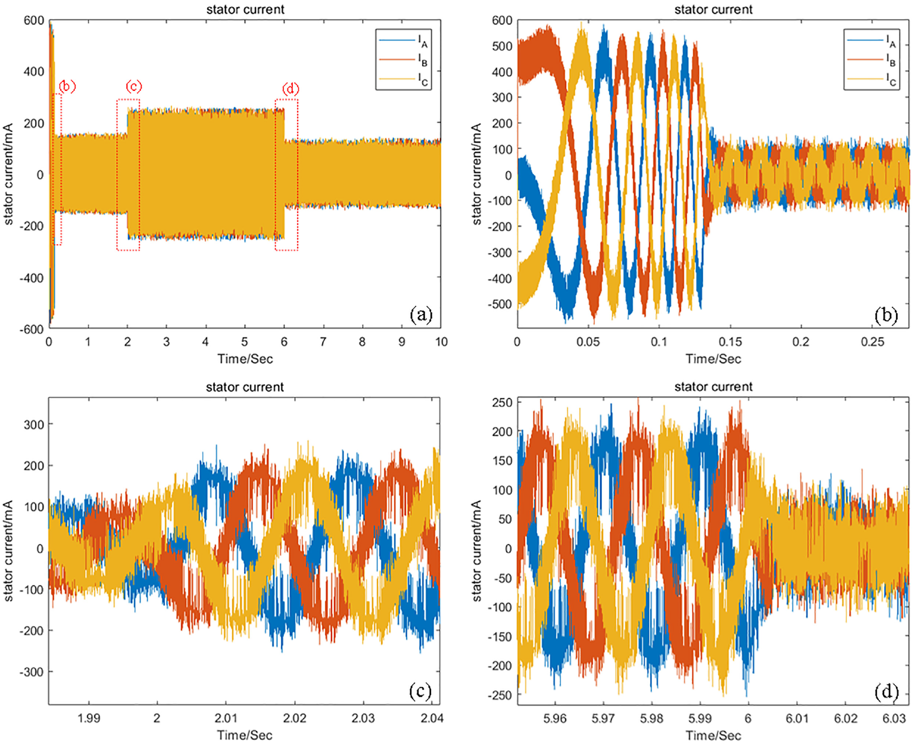
Stator current diagram of the electro-hydraulic pump during the load test: In Figure 8, Figure (a) shows the overall waveform, while Figure (b), Figure (c), and Figure (d) show the local amplification of the waveform circled in Figure A, which can more intuitively demonstrate the strong following ability of the control strategy.
Forward and reverse test
We also conducted positive and negative rotation tests on the electro-hydraulic pump system. The control target was set to 1500 rpm, the load application time was set to 2 s, and the end time was set to 8 s. At the fifth second, forward and reverse commands were sent to the system. The initial operation of the electro-hydraulic pump was defined as forward rotation, and the command in the fifth second was for the reverse rotation of the electro-hydraulic pump.
Speed
Figure 9 depicts the rotational speed waveform during the forward and reverse tests of the electro-hydraulic pump control strategy. Based on the simulation results, the operating speed of the entire electro-hydraulic pump stabilizes at the target speed of 1500 rpm within 0.12 s. Once stabilized, a load is introduced to the system. Notably, when switching the rotation state from forward to reverse, the speed responds promptly to the command, achieving a response time of 0.03 s. This rapid response is accompanied by minimal overshoot, measuring only 5% above the target speed, and a fast recovery speed of 0.02 s. Upon cessation of the system load, the speed returns to stability once again, demonstrating a consistent and reliable performance. The overall followability of the system is excellent, with a tracking error of less than 2%.The forward and reverse test results indicate that the overall electro-hydraulic pump system possesses robustness and stability. The system is able to maintain stability even under varying load conditions, ensuring consistent performance throughout the testing process. The control strategy employed fulfills the test requirements, demonstrating its effectiveness in managing the complex dynamics of the electro-hydraulic pump.
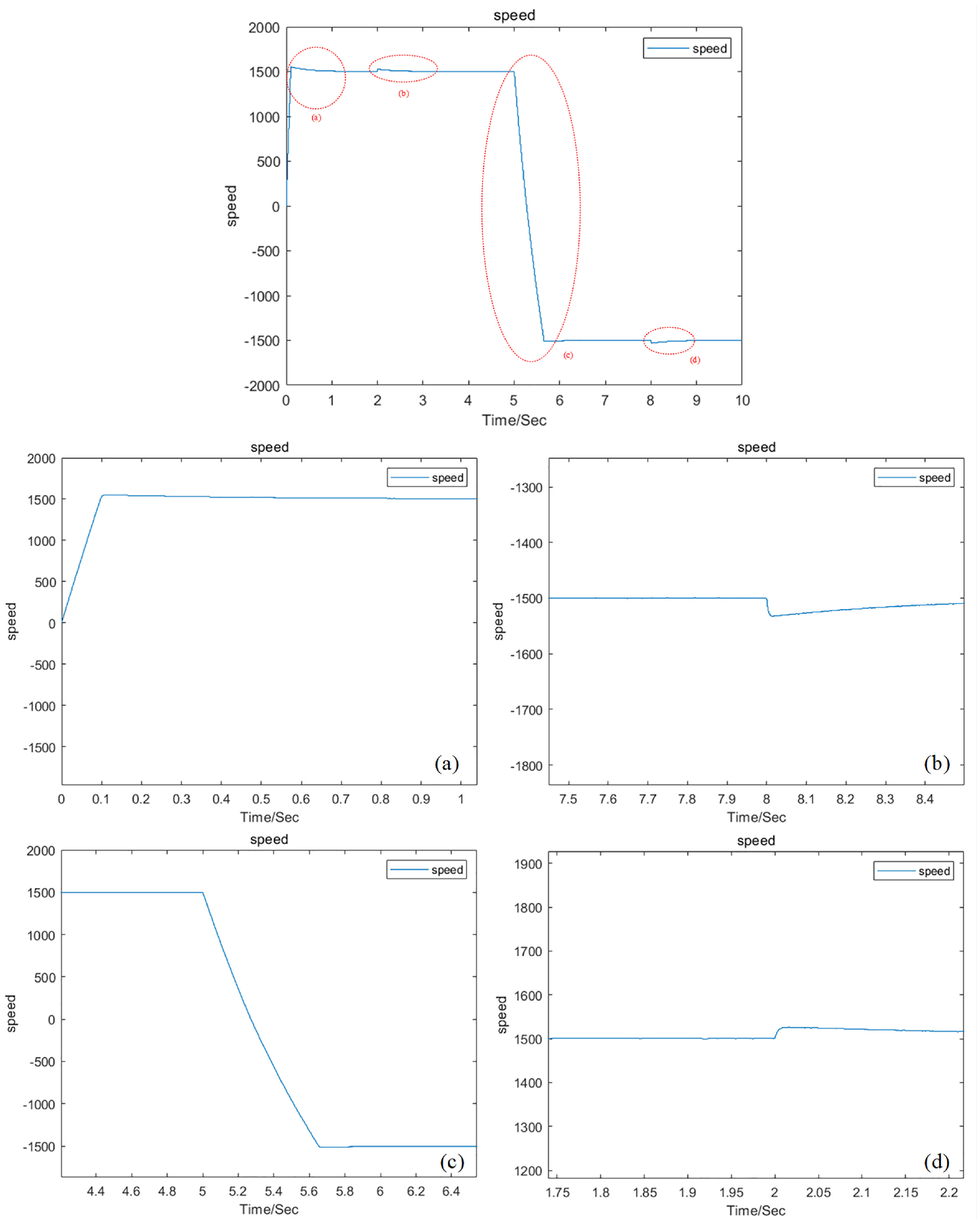
Speed diagram of the electrohydraulic pump under forward and reverse tests: In Figure 9, the first figure shows the overall waveform, while Figure (a), Figure (b), Figure (c), and Figure (d) show the local amplification of the waveform circled in the first figure, which can more intuitively demonstrate the strong following ability of the control strategy.
Stator current
Figure 10 shows the three-phase current results of the stator of the electro-hydraulic pump. According to the simulation results, the initial current of the overall simulation results is relatively large, which provides sufficient electromagnetic torque for the overall system control. When the speed meets the expected requirements, the current tends to be stable. After the system is stable, when the system is loaded, the stator current increases accordingly. When the system speed returns to the expected set parameter target, the stator current tends to be stable. When the operating target of the electro-hydraulic pump is switched from forward to reverse, the stator current fluctuates again, but the fluctuation time is short. When the stator current stabilizes, the system enters a stable state again. When the load stops, the current returns to the stable state before the load. During this process, large fluctuations in the current are observed.
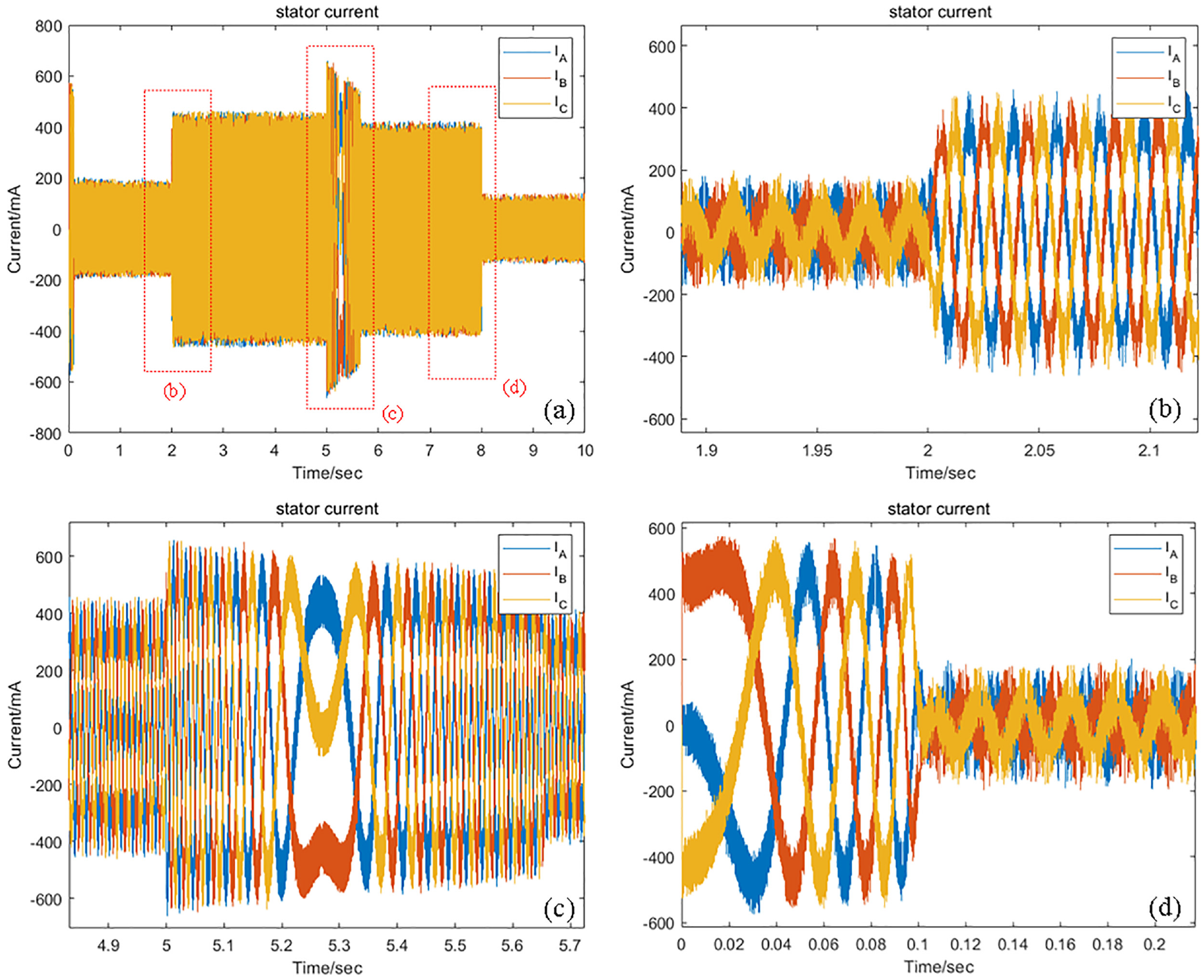
Stator current diagram of the electrohydraulic pump under forward and reverse tests: In Figure 10, Figure (a) shows the overall waveform, while Figure (b), Figure (c), and Figure (d) show the local amplification of the waveform circled in Figure A, which can more intuitively demonstrate the strong following ability of the control strategy.
Comparative simulation test
In order to comprehensively validate the superiority of the proposed sensorless control method in the full-speed range for an electro-hydraulic pump, this section conducts a comparison with different control methods. As shown in Figure 11, C1 represents the step signal simulation, where the expected step signal is 0 rpm from 0 to 0.2 s, then rises to 1500 rpm after 0.2 s, followed by the application of load at 2 s and unloading the load at 8 s. C2 represents the traditional PID control algorithm, C3 employs a low-speed domain high-frequency injection method with the extended Kalman filter algorithm in the mid-to-high-speed range. Finally, C4 corresponds to the control method proposed in this paper. In comparison to other control methods, the proposed control method in this paper demonstrates stronger disturbance rejection capability and faster dynamic response, further confirming the rationality of the proposed approach.
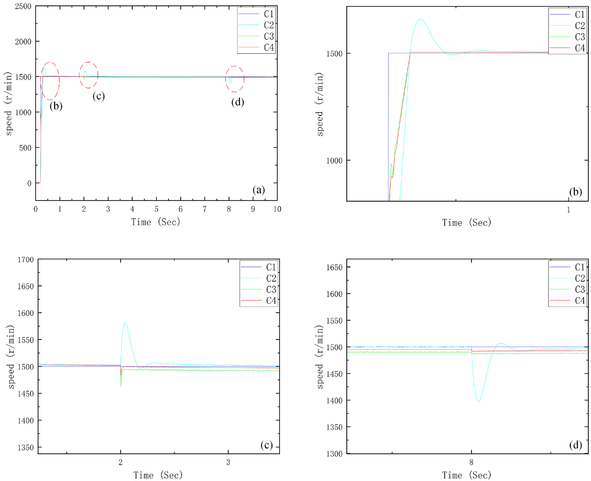
Comparative simulation test figure: In Figure 11, Figure (a) shows the overall waveform, while Figure (b), Figure (c), and Figure (d) show the local amplification of the waveform circled in Figure A, which can more intuitively demonstrate the strong following ability of the control strategy.
Experimental test
Figure 12 displays the speed waveform of the proposed control algorithm in the experiment. In this experiment, within the time range of 0–5 s, the desired speed undergoes a sinusoidal variation within the range of positive 800 rpm to negative 800 rpm. At the fifth-second mark, the speed undergoes a sudden change to 1000 rpm and continues sinusoidal variation within the range of positive 1500 rpm to negative 1500 rpm. Additionally, at the 2-s mark, an external load is applied to the system, and the load is unloaded at the 8-s mark. By comparing the actual speed with the given target signal and simulated speed, the rationality of the control method is further validated. It can be observed that the proposed control method exhibits good tracking and dynamic performance in the experiment.
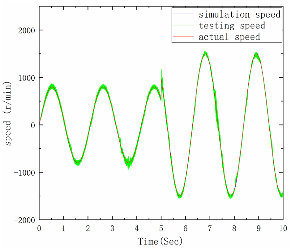
Experimental motor speed figure.
Figure 12 illustrates the three-phase stator current results during the actual operation of the electro-hydraulic pump. From the waveform graph of the stator current, it can be observed that this control method enables the stator current to operate smoothly within the rated range during actual motor operation. During abrupt changes in motor speed, the stator current exhibits a rapid response without significant fluctuations, further validating the feasibility and rationality of this control method. These findings underscore the significant engineering value of this control method in the field of electro-hydraulic pump control (Figure 13).
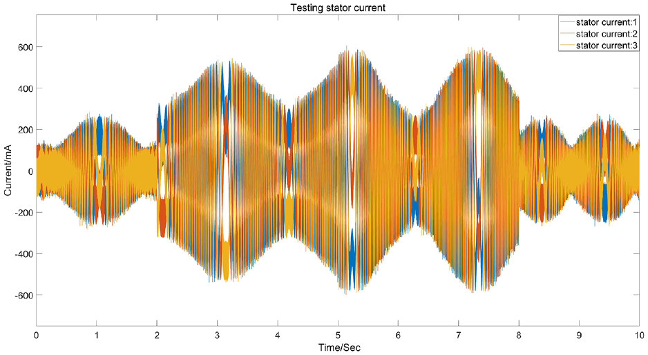
Experimental stator current figure.
Conclusion
In the manufacturing industry, a primary objective is to maximize production benefits while minimizing energy consumption. To achieve this goal, hydraulic systems are evolving towards incorporating intelligence, energy savings, and system integration. The hydraulic motor pump represents a promising approach to realizing these objectives. A two-dimensional plunger hydraulic motor pump, combining a two-dimensional plunger hydraulic pump with a permanent magnet synchronous motor, offers the advantages of a compact structure, high power density, and high efficiency, making it an ideal choice for the development trend of intelligent hydraulic systems.
In terms of the overall control strategy for the motor-hydraulic pump, sensorless position control is preferred over traditional position sensors. This implementation eliminates the need to reserve space for sensor installation in the electro-hydraulic pump structure, making it an ideal choice for compact electro-hydraulic pump systems.
To optimize the control strategy and better meet system requirements, a pulse vibration high-frequency injection method for low-speed motor conditions and an optimized extended Kalman filter algorithm for mid-to-high-speed motor conditions are combined. This enables the motor system to achieve sensorless control across the entire speed range, showcasing strong robustness and good responsiveness, thereby validating the feasibility and rationality of full-speed domain control for the electro-hydraulic pump.
The findings of our study have broad application prospects, particularly in scenarios with strict volume and mass restrictions, such as the aerospace industry. By achieving high efficiency, energy savings, environmental protection, and a high degree of information integration and intelligence, we propose that the development trend of the two-dimensional plunger hydraulic motor pump aligns perfectly with intelligent hydraulic systems.
Footnotes
Declaration of conflicting interests
The author(s) declared no potential conflicts of interest with respect to the research, authorship, and/or publication of this article.
Funding
The author(s) disclosed receipt of the following financial support for the research, authorship, and/or publication of this article: This work was supported in part by Zhejiang Basic Public Welfare Research Project under Grant LGG22E050032,Zhejiang Provincial Natural Science Foundation of China under Grant No. LQ19E050009 and National Key R&D Program of China (2022YFE0198900).
Data availability statement
The data used in this study are not currently included directly within the article. We understand the need for data sharing, but due to privacy and security considerations, we have chosen not to make these data publicly available. However, for sincere academic purposes, we are willing to provide the data upon receipt of an appropriate request via email communication. Interested researchers are kindly requested to contact the corresponding author at [corresponding author’s email address] to further discuss the possibility of data sharing.