
Abstract
The motion control library is a standard set of functional blocks integrated in a programmable integration environment, which is of great significance for the rapid development of reconfigurable Programmable Automation Controllers (PAC). However, due to the encapsulation and concealment of function blocks and the incompatibility between software and hardware, the development efficiency of function blocks is low, which is not conducive to the development of autonomous, controllable PAC. Aiming at the above problems, the methods of function block opening and key technology are studied, and a kind of motion control function library architecture and rapid development method based on the PLCopen specification are proposed. A series of motion control function libraries are developed on domestic PLC software. An experimental platform based on domestic hardware and software was designed to verify the typical motion control function library. Experimental results show that this method can effectively shorten the development cycle and that the developed motion control module can meet the actual control needs.
Introduction
The development of motion control systems has always been the key technology in the field of electromechanical control. More and more users are looking for industrial control systems with high standardization, strong portability, good openness, and rapid development.1,2
At present, the programmable logic controller (PLC) has been widely used and has become the carrier and core of intelligent manufacturing systems. 3 Through the programing development mode in accordance with the PLCopen specification, different types of components are integrated efficiently, and the function blocks are used to control CNC, robots, and other equipment.4,5 Based on the PLCopen specification, Krzysztof et al. 6 combine the motion trajectory generation with the algorithm through the rapid generation of the PLCcoder and prove the effectiveness of this method. The PLC motion control specification integrates PLC logic control, robot control, and CNC programing into the SME programing platform, which provides the basis for the development of standardized motion control systems and creates the architecture of embedded CNC systems.7,8 The ISG Kernel control software package developed by the ISG Institute of the University of Stuttgart in Germany provides a series of control software solutions for mechanical motion, CNC, robots, and so on, which can be embedded in IEC61131-3 programing software. 9 However, the openness of the developed product is poor, and its application in the actual system needs to be studied. Xu et al. 10 and Wang et al. 11 of Zhejiang University of Technology designed the six-axis robot control system of the PLCopen specification based on the Codesys development environment and EtherCAT communication protocol. Aiming at the research of the PLCopen control algorithm, the researchers of Huazhong University of Science and Technology proposed a hierarchical model of motion control system and function block interruption mechanism and realized the basic motion function block based on the PLCopen standard. 12 In order to solve the problem that single-axis and multi-axis function blocks with master/slave structures cannot realize complex multi-dimensional motion control, Fukang et al. studied the execution mode, parameter preservation, and transfer method of axis group function blocks and put forward the structure queuing method. The function block of axis groups is designed, and the multi-axis coordinated motion control is completed. 13 Li of South China University of Technology studied the acceleration and deceleration control and multi-axis straight line and arc interpolation algorithms within the function block and carried out experimental verification on the self-designed soft PLC platform. 14 A methodology is presented to automatically reconfigure the simulation environment and controller in PLC programing. 15 To achieve these standards, safety PLCs (SPLCs) are used, and the supervisor has to be split into a regular part and a safety part for SPLC implementation. 16
These research projects developed function blocks by directly programing in a specific development environment, which increases the programing requirements and difficulties. In this paper, the design and development modes of motion control function blocks are studied, and a motion control function library architecture and fast generation method are proposed on the basis of the PLCopen specification. By using the rapid development technology of function blocks, the development problems of many function blocks are solved, and the development rate is improved. The motion function library is developed for the target object, and the robot and CNC motion control simulation system are built by calling the function blocks in the library. The experiment is carried out on the experimental platform, and the results show that the proposed method can effectively reduce the programing difficulty, shorten the development cycle, and enhance the reusability of the program at the same time. It is also verified that the self-developed function library can achieve complex motion control functions.
PLCopen specification
At present, the PLCopen specification has been widely studied and applied in the field of motion control. PLCopen has successively formulated motion control, logic control, security control, OPC-UA, XML coder exchange, and other specifications according to IEC61131-3 standards and has been applied and promoted by domestic and foreign manufacturers and institutions. This specification enables PLC logic, robot control, and CNC control to be integrated into the same programing platform. The cross-platform use of programs or codes can be realized through the XML specification.
PLCopen motion control specification
The motion control specification provides a framework for the development of standardized motion control libraries, which coordinate different development platforms in the various stages of development, installation, and maintenance under the IEC standard development environment, so that the above links can meet the standardization requirements of motion control function blocks and achieve the goal of software definition control. The specification can be divided into six parts as shown in Figure 1.
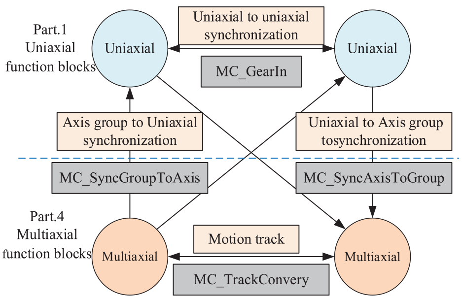
Uniaxial motion and multiaxial motion conversion.
Parts 1–3 are the motion control function block, the extended motion control function block, and the user guidelines, respectively. Part 4 extends the multi-axis motion control function of Part 1 and Part 2 in three-dimensional space. The motion relation between uniaxial and multiaxial is controlled by corresponding functional blocks, such as MC_SyncAxisToGroup. Part 5 extends the coordinate system transformation function for motion. The above specifications lay the foundation and framework for software-defined control and establish standards for the design and development of motion control function blocks. Finally, the realization of a fully autonomous and controllable development ecology for manufacturing equipment.
The realization principle of function block
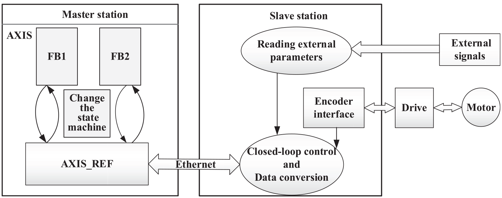
As shown in Figure 2, In the PLCopen specification, the realization of the function block depends on three basic elements. The logic control and algorithm realization of the motion control function block, the axis state machine, and the axis information collection The motion control function block executes the input and output instructions and the corresponding function algorithm. The axis state machine represents the current state of the axis and the possible state transition relationship. The axis information collection contains all the information parameters of the controlled axis in the current system. The motor control is achieved through the master and slave stations.
PLCopen function block implementation.
The execution of the function block is established on the state machine, and the axis can only be in one state when working. The transformation of the axis state can be realized through the execution of the function block. According to the PLCopen specification, the state machine is divided into two types: single-axis and axis groupas. There are 8-axis state machines, including three non-running state machines such as energy prohibition, error stop, and static state machines, and five running state machines such as stop motion, zero-return motion, synchronous motion, discrete motion, and continuous motion. The state change of the axis can be divided into two situations: one is the change caused by the normal execution of the function block, and the other is the state change caused by the error of the function block execution or the failure of the system.
Layered structure design of function block
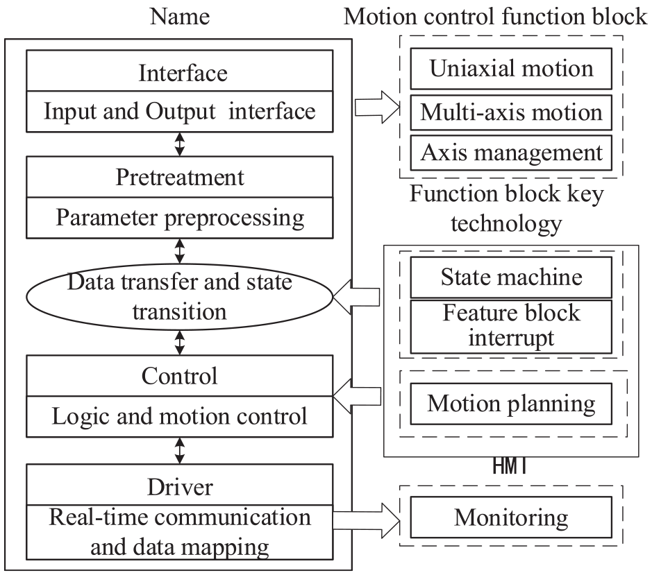
The PLCopen specification only defines the external definition and does not define the logic framework within the function block, so users are required to develop programs and logic codes according to the actual needs of the project to form a standardized algorithm structure and control flow, as shown in Figure 3. A standard function block is divided into two parts: internal logic and an external interface. The external interface includes input and output variables (including variable types), function block name, and type. The internal logic is divided into an interface layer, a preprocessing layer, an axis state layer, and a logic algorithm (motion control core).
Functional block hierarchical structure.
Function block development method based on PLCopen specification
The development of motion control function block
The function block is the core of the control system, and its development method is also gradually enriched. At present, there are two main ways of developing. One is to use the IEC standard language to program directly in the development environment, and the code generated by this method can be used directly. However, due to the limitations of the computing power of the development software, the development of functional blocks containing a large number of professional mathematical operations will increase the programing difficulty, such as the development of forward and inverse kinematics-solving function blocks for robots. The other code is generated automatically by PLCcoder with the help of other development software or mathematical software, and the compatible code is imported into the target development environment, which can solve a large number of complex mathematical operation function block development problems based on the PLCopenXML specification. This method can generate code through the model and can directly simulate and check the code in the generating software. Compared with the traditional development method, its development efficiency is significantly improved and can be used for the rapid development of complex function blocks.
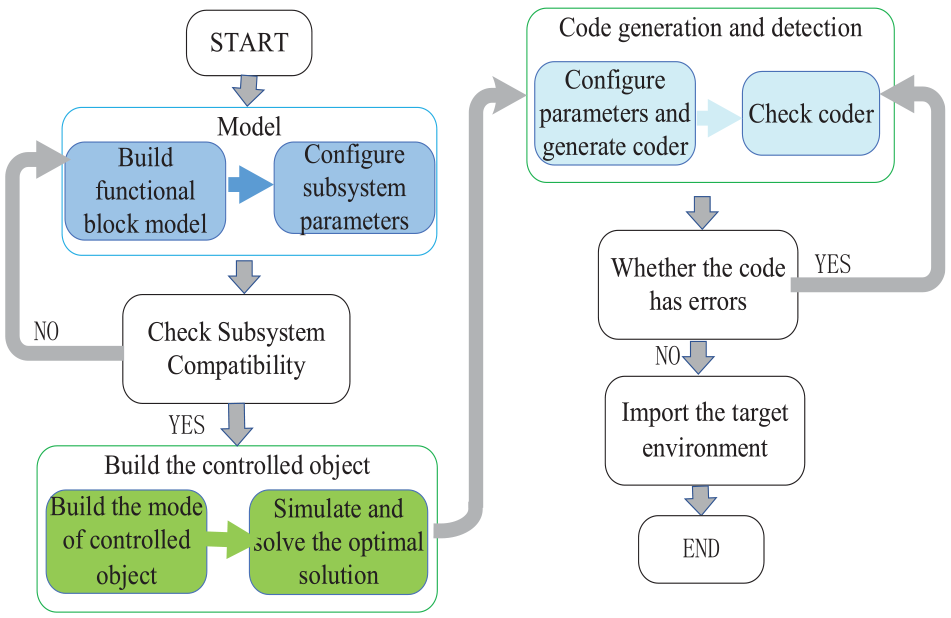
The rapid development method is shown in Figure 4. In the preprocessing stage, the engineering requirements are analyzed, and the target controlled object and its related parameters are determined. The corresponding control algorithm is established in the mathematical software and models of the controlled object. Due to the different encoder standards, it is necessary to check the compatibility after the establishment of the subsystem. If it does not meet the standard, the model and subsystem are adjusted; otherwise, the target model is simulated to verify whether the model meets the requirements of the target project. The simulation of the model can effectively reduce development errors and modify the model and parameters over time. After the model simulation passes, the corresponding PLCcoder is generated according to the target development environment.
Rapid development process of function blocks.
The solution function block of robot inverse kinematics is considered an example; the ST code generated by the above method is shown in Figure 5 and imported into BEREMIZE in Figure 6.
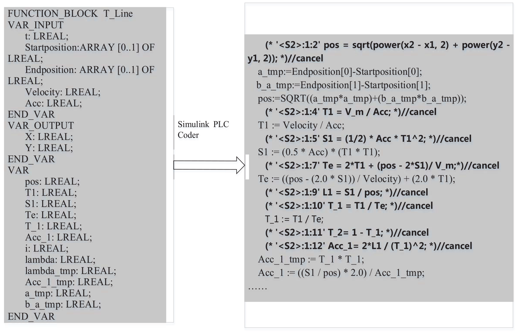
The generated ST code.
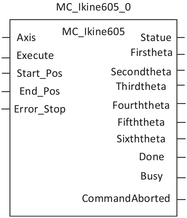
The function block of inverse kinematics.
Overview of motion control function library
The motion control function library is a collection of function blocks and functions that can be used to realize single-axis motion, multi-axis motion, and interpolation motion, as shown in Figure 7. The function blocks in the library can be divided into single-axis and multi-axis/axis group function blocks according to the number of axes, and each category can be divided into axis motion control and axis management function blocks according to functional attributes. The motion control function block is used to drive single-axis or multi-axis motion, such as the interpolating (interpolation) function block and Home (return to zero) function block, while the management function block is used for axis management, parameter configuration, and state monitoring, such as Power (enable) function block and ReadStatus (axis state reading) function block.
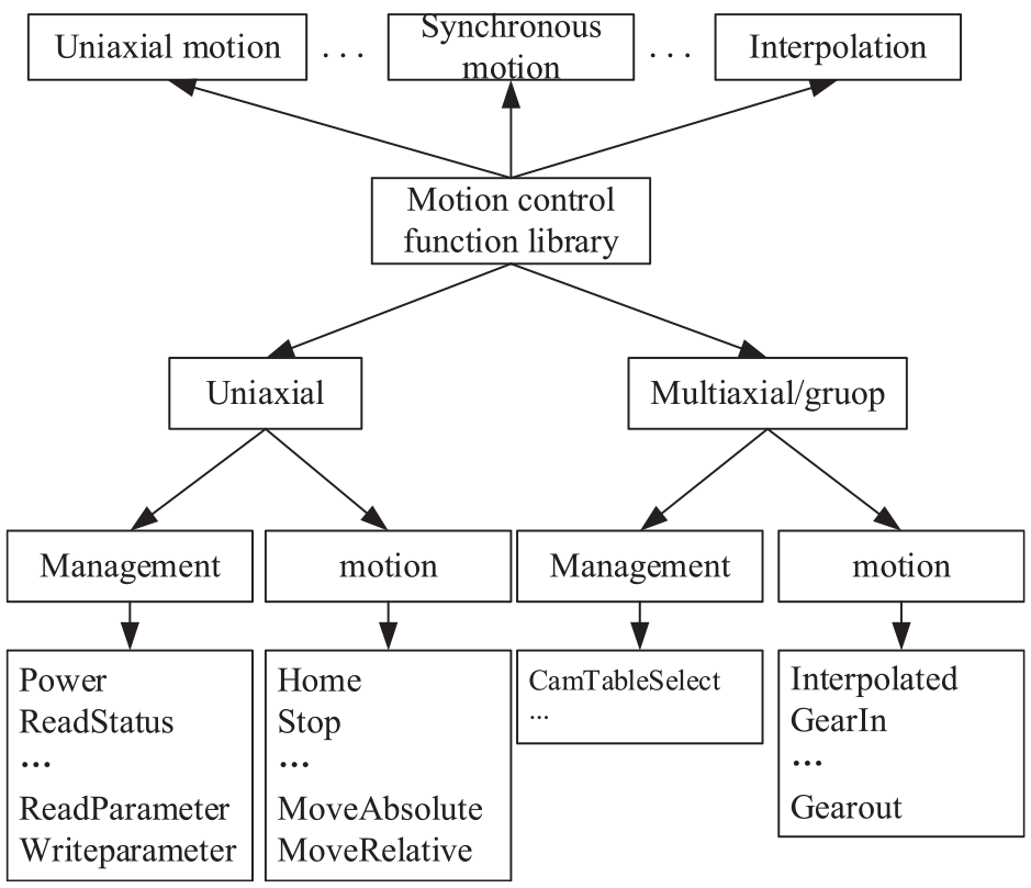
Function block types.
Architecture of motion control function library
At present, although a set of standardized function block libraries has been developed in foreign software, they can be called directly. But because of the encapsulation of the function library and the concealment of the program, the internal algorithm and logic cannot be changed, which is not conducive to the rapid development and real-time modification of the control system or to the development of autonomous controllable systems. And there is no well-established function library in the self-developed development environment, such as Beremize, so the development of the function library is the core of the autonomous controllable PAC system. The motion control function library can be composed of an engineering and library information module, a variable and instruction module, and function blocks, as shown in Figure 8. The library name and library information can be set in the information module. The driver interface and data type are defined in the variable and instruction module, which is different from the standard data type, and the frequency data type is the custom data type under the PLCopen specification. Function blocks and function modules are the core of the library, and different motion control libraries correspond to different sets of function blocks, such as single-axis motion control libraries and multi-axis motion control libraries, which contain different function blocks. After the development of the read function block, the user can encapsulate it into the library and call it directly when it is used.
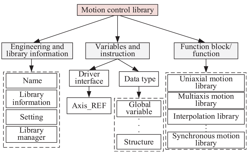
Structure of function library.
Development and implementation of PLCopen motion control function block
Function block development of axis management class
The motion management function block mainly realizes the parameter configuration and state reading of the motion control slave station, including power-on enable, control parameter configuration, feedback parameter configuration, reading error information, and so on. The master station configures the parameters of the slave station by sending SDO communication. In order to ensure the real-time validity of the data, the function of reading the status, actual position, and actual speed of the axis is realized through the Ethernet periodic process channel (RPDO) between the master and slave stations.
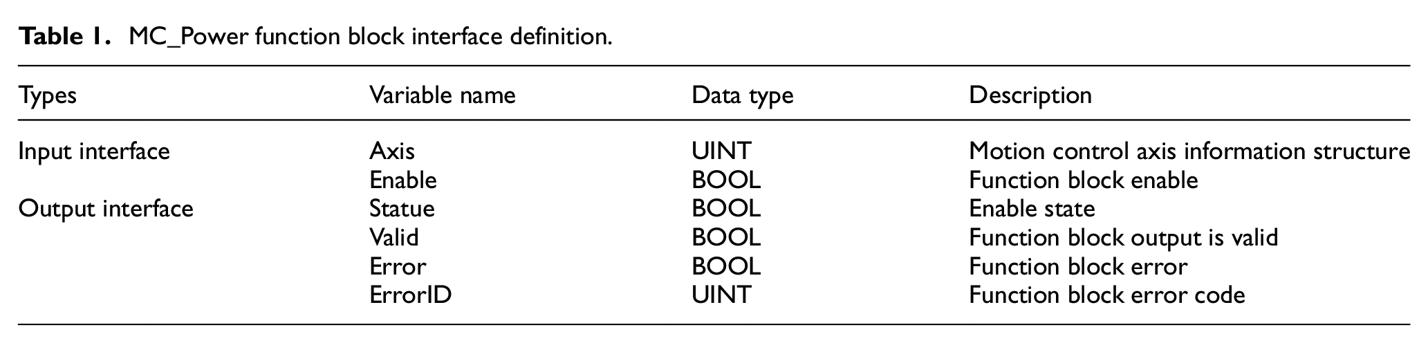
The MC_Power function block is used to control the switching of the servo state machine of the motion control slave station. The driver is enabled to power on, and the working status of the system is monitored at the same time. The interface definition is shown in Table 1. When Enable is true, the driver is ready, and the state status is displayed as True, as shown in Figure 9. While the state machine of the axis changes from a disabled state to a static state, waiting for control instructions to be input, If the slave station fails the state machine or the driver returns the servo alarm signal, the status is still false, indicating that there is a hardware problem in the system. The axis will be switched to the error-stop state, and the hardware problem will be fixed before using the system.
MC_Power function block interface definition.
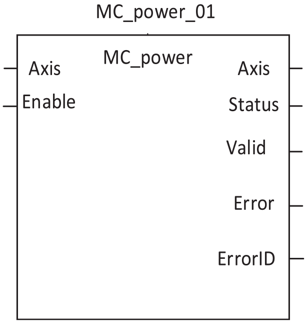
MC_Power function block instance.
Uniaxial motion control control function block
The uniaxial-axis motion control function block is the basic element in the motion control library. The commonly used uniaxial motion control functions include return to zero (MC_Home), speed control, absolute motion (MC_Absolute), relative motion (MC_MoveRelative), and so on.
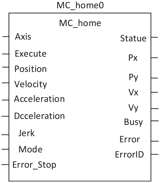
MC_Home
The zero-return function block is used to find the location of the axis reference point, which is an indispensable function in the practical application of the motion control system. The motion control system using an incremental encoder will lose the memory of the original reference coordinate system after a restart or emergency stop, so it is necessary to return to zero first to make the system re-establish the reference point and reference coordinate system as shown in Figure 10. The rising edge trigger mode is used for the function block; position is the reference point position; set to zero is the origin; and calibration represents the zero switch signal. Homing_Mode indicates that there are many ways to return to zero. The return to zero operation is generally the first action instruction after the motor is enabled. When the execute is triggered, the axis state machine changes to the return zero motion state. When the return to zero operation is completed, the axis stops automatically, and the state machine automatically turns back to the static state.
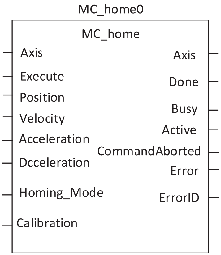
MC_Home function block instance.
MC_Absolute&MC_MoveRelative
Absolute motion and relative motion function blocks are commonly used motion control function blocks. Absolute motion function blocks are used to move to a specified absolute position with specified parameters, while the relative position is the relative distance of motion. Different parameters will get different motion trajectories, so speed planning is the core of this kind of function block. This paper designs and develops this kind of function block. An example of this function block is shown in Figure 11.
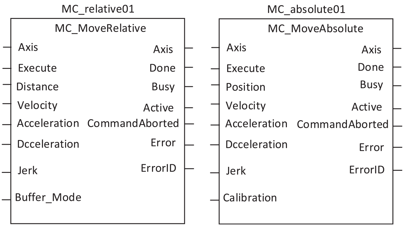
MC_Absolute and MC_MoveRelative function block instance.
The relative motion and the absolute motion function blocks are connected. First, the relative motion is performed, and the absolute motion is performed for the interruption of its motion state during execution. The parameters are set as shown in Figure 12.
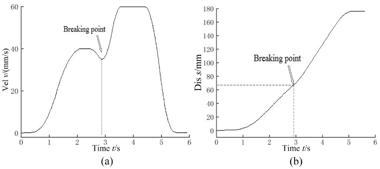
Result of function block execution: (a) velocity curve and (b) displacement curve.
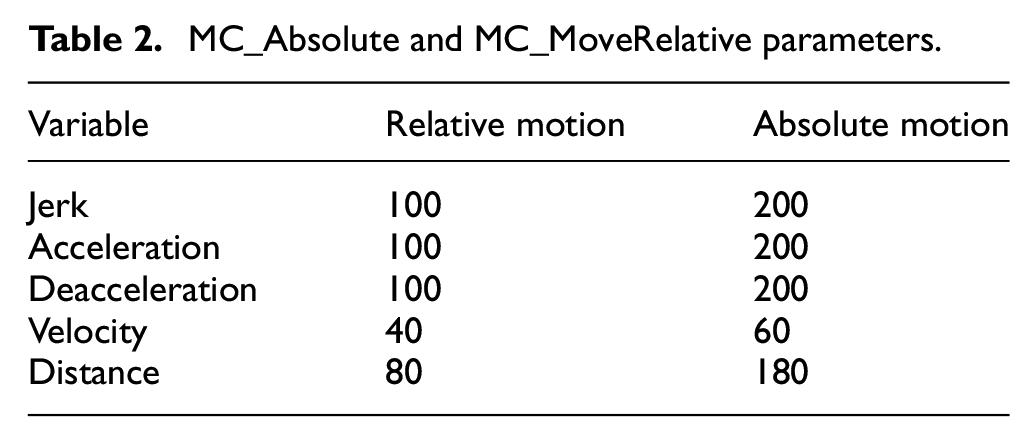
The two function blocks use S-type acceleration and deceleration modes, as shown in Table 2, to interrupt the relative function blocks and execute the absolute function blocks at the end of 3 s. The results show that the two function blocks can effectively realize the relative and absolute motion of the axis.
MC_Absolute and MC_MoveRelative parameters.
Multi-axis motion control function block
The realization of multi-axis motion includes multi-axis synchronous cooperation and an arbitrary trajectory in space. A series of motion control function blocks are developed for commonly used multi-axis motion in this paper, such as two-axis and three-axis linear interpolation, arc interpolation, and so on, as shown in Figure 13. The MC_Interpolator two-axis interpolation function block can realize arc and straight line interpolation. Through the rising edge trigger, the interpolation motion is controlled by user-specified parameters.
Two-axis interpolation function block.
Experiment and simulation
The Huazhong CNC HSR-JR605 robot and CNC system are taken as the control object, and the corresponding motion control function library is developed, which is verified by experiments on the self-built experimental platform. The experimental platform consists of master and slave stations, a real-time Ethernet bus, a logic programing environment, user monitoring software, and other modules.
The master module is the core of the system logic program execution and task scheduling, mainly executing the compiled IEC 61,131 logic program calculation, data communication between the slave nodes based on real-time Ethernet, and data exchange over the human-machine interface. Through real-time Ethernet bus communication, the master station can perform real-time task scheduling, parameter modification, comprehensive monitoring, and node management for each slave network node in the distributed architecture, thus realizing efficient control of the PAC system as a whole.
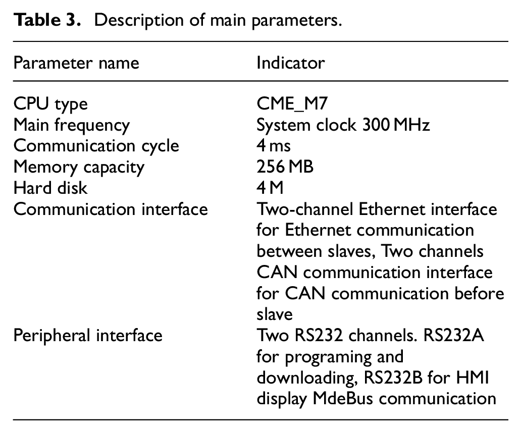
For the development needs of the control system, this paper adopts the embedded master station of the M7 based on a domestic processor, whose main hardware composition and technical indexes are shown in Table 3.
Description of main parameters.
The MC motion control slave was designed and developed with the CiA402 protocol as a reference. A range of parameters are used to select and configure them, such as real-time communication, axis motion control modes, input and output data polarity, feedback sensor type, and controller parameters. Two complete control loops can be formed inside the slave station, which can meet the control needs of most domestic and foreign servo drives and motors. There are two types of output commands and types for motion control slaves, corresponding to different slave control functions. When the output of the slave station is pulse quantity, the slave station is in the open-loop state, and when the output of the slave station is analog quantity, closed-loop control can be carried out inside the slave station at this time, and its control principle is shown in Figure 14.
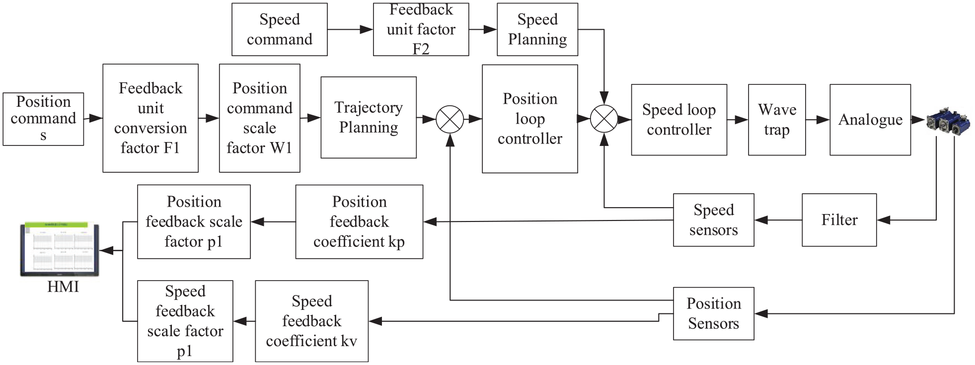
Slave closed-loop control scheme.
The self-developed NCUC2.0 real-time Ethernet controller is based on an “FPGA” functional IP core design and supports the CANopen protocol layer. The master sends the network data to port 1 of slave 1 through the Ethernet interface, and the NCUC controller processes the data and sends it from port 2. Port 1 of slave 2 receives the data from slave 1 and sends it to the next slave through port 2. Until the last slave, N, receives the data, it returns directly to the master via port 2.
Motion control function library simulation system
The system consists of a master station, a slave station, a real-time Ethernet bus, host computer software, user monitoring software, and so on, as shown in Figure 15. Real-time Ethernet adopts the high-performance NCUC2.0 bus protocol, and the communication cycle is 1 ms. Logic programing software and HMI monitoring software run on the PC and communicate with the system master station on Modbus or TCP/IP to complete control program code download and real-time data exchange. On the upper computer, Modbus or TCP/IP communication is carried out with the system master station to complete the control program code download and real-time data exchange.
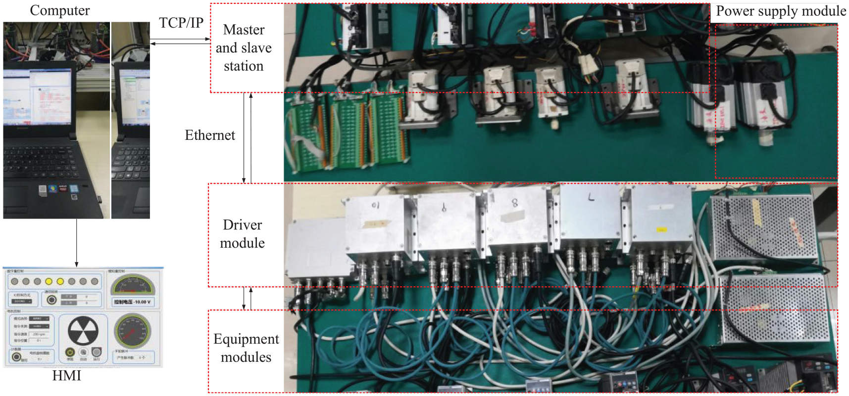
Control experimental platform.
The hardware of the system mainly includes the master station, slave station, bus communication controller, servo drive device, and peripheral equipment. The master station is the core and “brain” of the whole PLC system, which is mainly used to complete functions such as real-time task scheduling. Logical information operation of the compiler environment, instruction and communication control to each slave station, HMI data exchange, and so on The slave station mainly operates the equipment according to the instructions of the master station, including the acquisition and output of the sensor, and realizes data exchange and communication with the master station through the Ethernet bus controller. The Ethernet bus communication controller is located in each slave station module, which mainly realizes high-bandwidth, high-efficiency, and high-speed data transmission between the slave stations. The servo drive device and equipment are the actuators of the system to complete the motion control. The system software mainly includes IEC61131 standard software, an integrated development environment, and interface monitoring software. The software-integrated development environment is mainly used to realize system hardware configuration, visual system function design and logic program, logic code compilation, program executable file generation and download, etc. The interface monitoring software is mainly used for the design and development of human-computer interfaces to complete communication with the master station and ensure real-time monitoring of the master data.
When using the domestic PLC system, the hardware of the system is configured according to the control requirements, and then the standard program language is used to program the target variables or function blocks in the IEC61131-3 programing software, which associates the target variables with the data interface of the slave station.
Simulation of robot motion control
The self-developed robot motion control module consists of four parts, as shown in Figure 16(a). The axis management and enabling module uses the MC_power function block. The forward and inverse kinematics function block is used to solve the kinematics of the robot. The trajectory planning module is used for motion planning and giving instructions to the axis. It is also used to deal with emergency situations such as an emergency stop and alarm during the execution of the task, as well as reset and return to zero operations.
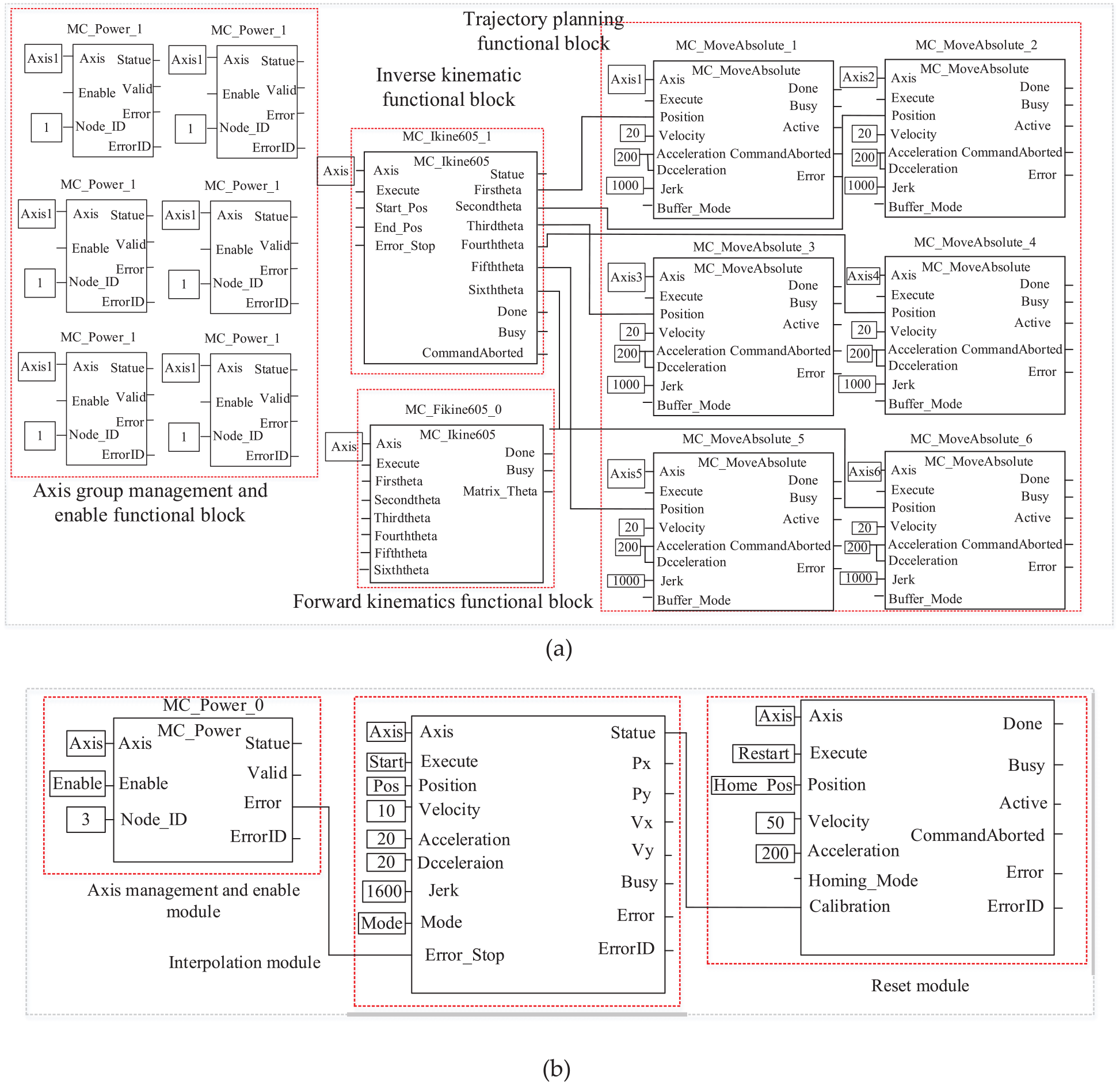
Robot and CNC motion control module construction: (a) robot motion simulation module and (b) CNC control module.
Taking the grasping motion of the robot as the target, the experimental parameters are set as follows: the coordinate of the starting position is A (250,0,0), the initial position is
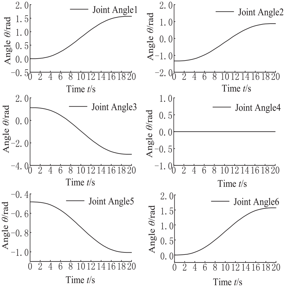
MATLAB simulation of joint angle.
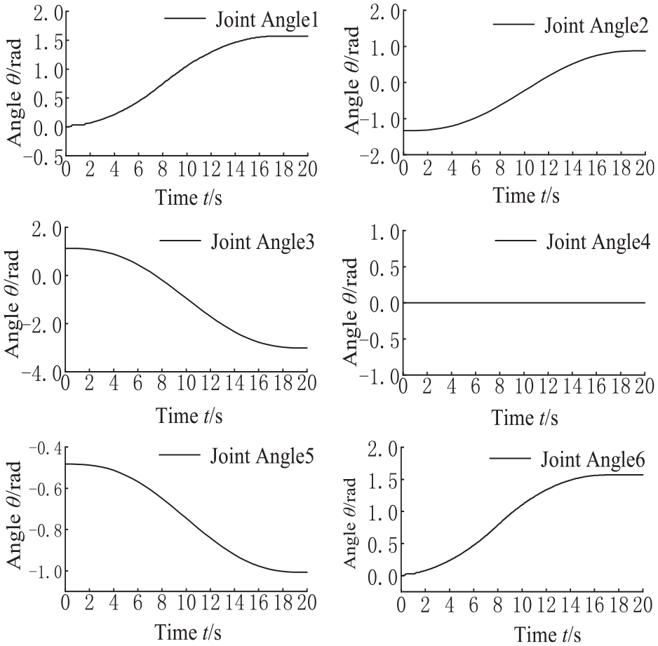
Actual motion curve of joint.
The results show that the trajectory jitter is caused by the communication delay in the early stage of the motor execution, and the actual trajectory can be well simulated in the later stage of the motion. Therefore, this method can quickly develop the robot motion control function block and verify the effectiveness of the control module built into the host computer software.
CNC motion control function simulation
Aiming at the special CNC system, a set of standardized CNC motion control function libraries is developed independently based on PLCopen in this paper. The model of the CNC motion control system is shown in Figure 16(b). MC_power is the axis enabling function block, MC_Interpolator is the interpolation motion control function block, and the MC_Home function block is the reset function block, responsible for the sudden stop of the axis and the zero-return movement of the axis.
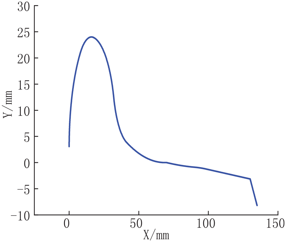
An experiment is carried out on the repair trajectory of the turbine in Figure 19. In order to meet the actual needs to reduce the start and stop of the motor, an asymmetric S-shaped speed planning is designed through the curvature threshold of each section. The Jerk of each paragraph can be obtained
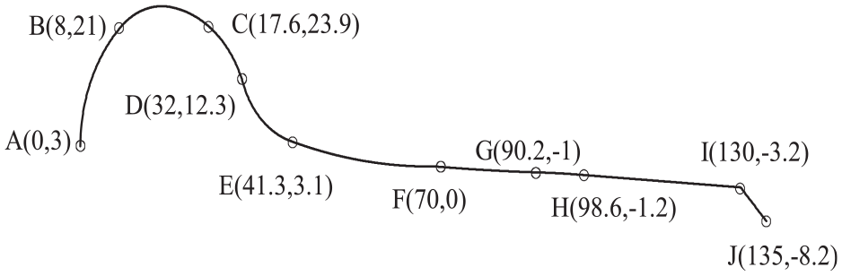
Target repair trajectory.
The execution result of the function block is shown in Figure 20, which shows that the function block can carry out multi-segment motion trajectory planning. The motion instructions are sent to the master-slave station, and the motor is driven to realize interpolation motion. The motion result is shown in Figure 21. The results show that the two axes move synchronously. Through the monitoring interface to the motor feedback track shown in Figure 22, the error between the actual track and the target track is less than 0.3 mm. The above results show that the self-developed CNC motion control function library can achieve a variety of motion planning tasks. The simple CNC linear interpolation and arc interpolation are simulated, and the synchronous motion of the multi-motor is realized, which preliminary verifies the effectiveness of the motion control library.
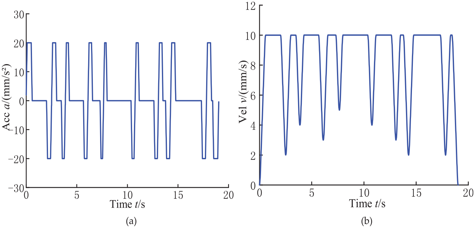
Acceleration and velocity curves: (a) acceleration curve and (b) velocity curve.
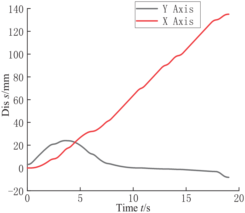
Interpolation displacement curve.
HMI feedback trajectory.
Conclusion
In order to solve the problem that the function block and library of numerical operation in PLC host computer software are not open, based on XML specification, PLCcoder technology is adopted to automatically generate structured text in accordance with the IEC standard, and the function block is developed quickly, which can meet the needs of mathematical operation in host computer software.
Based on the basic model of function blocks, the layered structure of function blocks is designed, and the key technologies of function block development in domestic development environments are studied. A series of motion control function blocks, such as robot and CNC, are developed by the rapid development method. And through this function block, the robot and CNC motion control function library are built, which can effectively save development time.
In the PLC host computer software, the robot motion control system is built using the rapidly generated robot and CNC motion control library, and the effectiveness of the control system is verified by the self-built control platform. Experiments show that this method can quickly generate the motion control function library based on PLCopen and solve the difficulty of numerical calculation in traditional PLC software. And through the self-built experimental platform, it has been verified that the control system can achieve independent development and control and can meet the needs of industrial control.
Footnotes
Author contributions
Conceptualization, W.JC and F.DP; Data curation, Y.YD and X.MB; Investigation, W.JC and Z.WL; Methodology, Y.YD and Z.WL; Writing-original draft, Y.YD and Z.LC. All authors have read and agreed to the published version of the manuscript.
Declaration of conflicting interests
The author(s) declared no potential conflicts of interest with respect to the research, authorship, and/or publication of this article.
Funding
The author(s) disclosed receipt of the following financial support for the research, authorship, and/or publication of this article: This research was funded by the Regional Innovation Foundation of China-Hunan Joint, grant number U19A2072.
Institutional review board statement
Not applicable.
Informed consent statement
Not applicable.
Data availability statement
The data presented in this study are available in this article.