
Abstract
The aim of this study is to propose a method for evaluating the comprehensive degree of nonlinearity in the dynamic response of high-speed maglev train system through mathematical modeling and numerical simulation. A model of a typical high-speed maglev vehicle is established based on the principles of maglev vehicle dynamics, and control models for the suspension magnet and the guide magnet are developed using principles from the electromagnetism and automatic control theory. The vibration responses of the vehicle system, including acceleration and electromagnetic forces are calculated using a fast numerical integration method. This calculation is performed for various control parameters and track harmonic excitations. The Hilbert-Huang transform (HHT) is adopted to decompose the response signal and derive the local mean frequency (amplitude) and instantaneous frequency (amplitude) of the response, based on which the Degree of Nonlinearity (DN) of the vibration response of a single component is obtained by calculating the deviation between the instantaneous frequency and the mean frequency. The Comprehensive Degree of Nonlinearity (CDN) of the vibration response in the maglev train system is proposed and defined by incorporating the DNs of the vertical and lateral vibrations of the carbody, bogie, suspension magnet and guide magnet, and by quantitatively evaluating them. The effects of the electromagnet control parameters and harmonic irregularities (wavelength and amplitude) of the track on the DN of each component and the CDN of the entire vehicle system are analyzed in detail. The analysis results show that the DN and CDN can demonstrate the extent of instability in the vehicle system and can be applied for safety warning on maglev vehicles.
Keywords
Introduction
The maglev train is a type of manned transportation tool based on the technology of electromagnetic levitation, and the high-speed maglev train is the fastest ground transportation tool at present, which can form high-speed “corridors” between large cities or between urban agglomerations. The maglev technology has been a research hot spot in the field of rail transit globally since its emergence.1–3 Currently, Germany,4–6 Japan,7–9 South Korea 10 and China11–15 are in the forefront of basic research and engineering application in this field. Since the beginning of this century, Germany, Japan, and China have successfully tested their high-speed maglev trains on their test lines, with a speed up to more than 500 km/h.
Unlike conventional wheel-rail trains, maglev trains have no contact with the track, therefore eliminating frictional losses and freeing them from wheel-rail adhesion restrictions, which means zero wheel-rail noise, lower pollution and carbon emissions and less maintenance costs. Due to the absence of mechanical transmission components such as wheelsets, axleboxes, traction motors, gearboxes, couplings, traction rods, bearings, etc., the mass of a maglev train is lighter than that of a conventional train, which means the disappearance of rolling noise generated by rotating parts such as bearings, gears, etc. Since the whole weight of the train acts evenly on the maglev track through electromagnetic forces, there is no wheel-rail contact stress concentration, effectively reducing the requirements for structural strength of the track. The use of multiple suspension magnet modules, guiding levitation modules, and guiding mechanism devices enables the maglev trains to have better curve-passing capability than ordinary wheeled trains. Additionally, the curve track radius can be designed to less than 50 m. As it does not rely on the wheel-rail adhesion to drive, the climbing ability of a maglev train is limited only by the adjustment ability of the levitation control system and the driving ability of linear motors, making the climbing capacity of a maglev train more than twice that of a wheeled train.
The propulsion, suspension and guidance functions of the maglev train are all realized through electromagnets. It is important to note that the electromagnetic force becomes a nonlinear function of the gap when the electromagnet reaches its maximum force. 16 When the maglev vehicle runs on the line, the dynamic behaviors of the suspension system are characterized by limit cycle motion, multi-frequency coupling, suspension instability vibration, etc. In the experiment, the vehicle-track resonance phenomenon caused by the nonlinear time delay of the control link was observed. Zheng et al. 16 found a nonlinear chaotic phenomenon in the study of the dynamic characteristics of the maglev vehicle. Due to the complex working environment and large load variation, the maglev train needs a nonlinear control system with strong control capability. If the nonlinear factors in the system are ignored, it may result in completely different dynamic behaviors.17–19
Since the 1990s, engineers have been engaged in developing classical control algorithms20–22 for stable levitation of maglev train systems based on a number of easily available field measurement signals such as the levitation gap, the speed and acceleration of the gap change, the solenoid current of electromagnet, the flux density of magnetic field, etc. In terms of model correction, the common practice at the time was that Taylor expanded the nonlinear terms of the system equations at the equilibrium point and then designed a linear control algorithm, but the linearization process caused the model to lose its nonlinear properties. The control algorithm designed in this way can only guarantee fast convergence of the system suspension gap with small errors. When the maglev train runs on the line, the small gap (10–20 mm) between the electromagnet and the maglev track makes the vehicle system extremely susceptible to instability under the excitation of nonlinear loads and track deformation.
No real physical system can be linear, so nonlinear models and system identification are used to get closer to the real models and real situations and thus to improve the control performance. Along with the development of nonlinear dynamics, microelectronics and automatic control technology, the accuracy of maglev train system control has been further improved. Various nonlinear control algorithms have been applied in the field of magnetic levitation control, such as decoupling control, 23 fuzzy control, 24 chaotic control, 25 robust control,26,27 STSMO (super-twisting sliding mode observer) control, 28 and adaptive control. 29 Therefore, it is of great theoretical and practical importance to study the nonlinearity of the maglev train system. One area of current research into the dynamics of maglev trains is the nonlinear vibration characteristics of the vehicle system. Due to the limited knowledge on the theory of nonlinear vibration, many problems cannot yet be analyzed by theoretical calculations, while the development of numerical calculation and the improvement of computing performance have made numerical simulation analysis possible. Huang et al.30–32 argue that the key feature of a nonlinear vibration signal that distinguishes it from a linear signal is whether that signal contains a frequency modulation or an amplitude modulation component, and propose to quantify the nonlinearity of a vibration signal based on the modulation phenomenon of the signal. Chen and Lin33,34 applied the method to study the effects of wheel polygonalization and hunting instability on the Degree of Nonlinearity (DN) in the dynamic response of high-speed wheeled vehicle system.
To date, there has been insufficient research into the nonlinear characteristics of the dynamic response of maglev train system, and there are still many unsolved scientific issues, such as how much do the key parameters of the suspension and guiding control systems affect the DN of the vibration response of a maglev train? How do the wavelengths and amplitudes of harmonic irregularities of the maglev track affect the DN of the vibration response? Is it possible to establish an evaluation index to comprehensively quantify the overall DN of the vibration of a maglev train system? These questions are answered in this study by the following work. In the second section, a typical high-speed maglev train model is established to calculate the vibration response of the vehicle system based on the theory of maglev vehicle dynamics. In the third section, a new nonlinearity evaluation index, the Comprehensive Degree of Nonlinearity (CDN), is proposed to evaluate the degree of nonlinearity of the entire vehicle system. Effects of the control system parameters and track harmonic irregularities on the DN and CDN of the vehicle’s vibration signals are analyzed in detail. The conclusions are drawn in the final section.
Model of high-speed EMS-Maglev train
Vehicle model
Based on different physical principles and application modes, the electromagnetic suspension technology of maglev trains is generally divided into two categories: one is Electromagnetic Suspension (EMS), and the other is Electrodynamic Suspension (EDS). The EMS is based on the principle of “opposites attract” to generate electromagnetic forces that suck the vehicle upwards, while the EDS uses the repulsive force generated by the magnetic field between the on-board magnets and the coils on the track to levitate the train. This study is aimed at high-speed maglev trains based on the EMS suspension technology, which has been successfully applied in engineering in Germany and China.
The main structure of a single EMS-maglev vehicle consists of carbody, bogies, secondary suspension system, primary suspension system and electromagnets, as shown in Figure 1. The carbody is mounted on four suspension bogies, each of which is fitted with suspension electromagnets and guide electromagnets. The bogies are connected to the carbody through the secondary suspension system and to the electromagnets through the primary suspension system. Each electromagnet is mounted on the bracket arm of the suspension bogie by two suspenders at the front and rear, enabling the transfer of electromagnetic forces to the bogie and the compensation of relative movements. The secondary suspension system transfers the suspension and guide forces from the bogies to the carbody, compensates for the relative motion between the carbody and bogies, and attenuates vertical and lateral vibrations and shocks transmitted from the bogies. The bogies are made of aluminum alloy, which allows for a lightweight structure with sufficient strength and stiffness. Each bogie consists of a longitudinal beam frame, two crossbeam frames and four C-shaped suspension frames. The support beams at the ends of each crossbeam frame are used to mount the air springs, and the brackets of each C-shaped frame are used to mount the suspension magnets and guide magnets.

Model of a single EMS-maglev vehicle: (a) side view and top view and (b) front view.
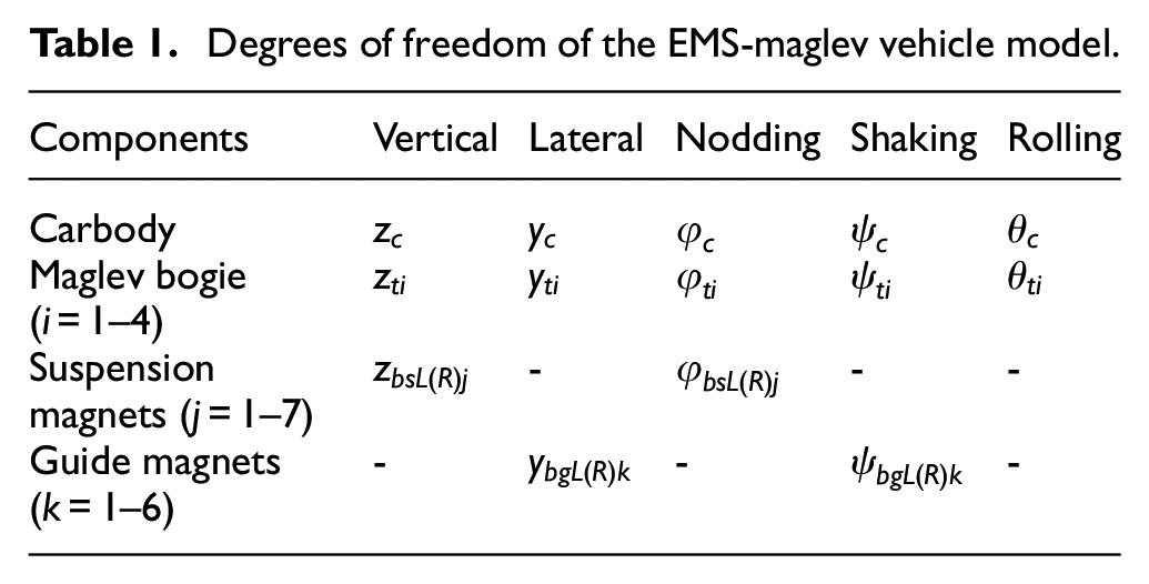
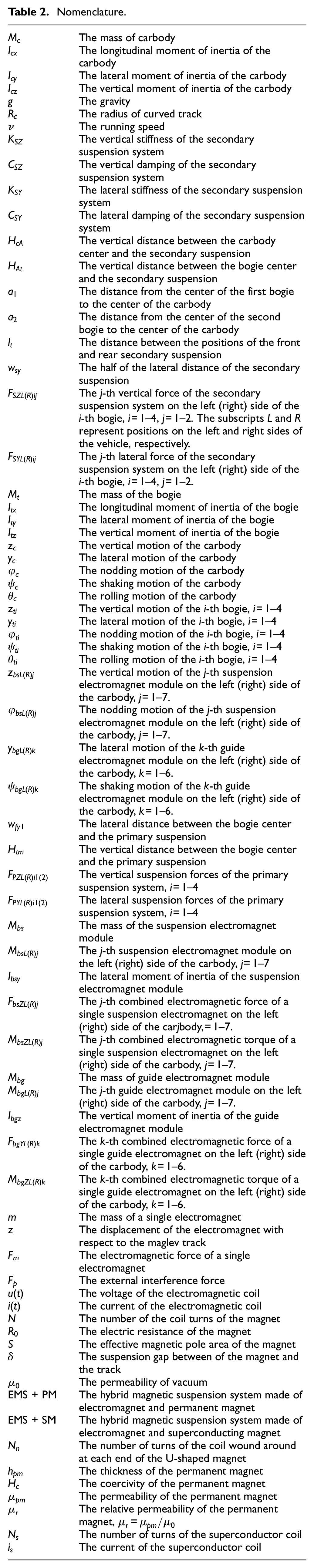
As shown in Figure 1, the developed maglev vehicle model consists of 1 carbody, 4 bogies, 14 suspension electromagnet modules, and 12 guide electromagnet modules. The carbody and bogies are designed with five degrees of freedom except for longitudinal motion, the suspension electromagnets with the vertical and nodding degrees of freedom, and the guide electromagnets with the lateral and shaking degrees of freedom. The entire vehicle system is designed with a total of 77 degrees of freedom and the degrees of freedom of each component in the model are shown in Table 1. The meanings of the parameters in the model and formulas are shown in Table 2.
Degrees of freedom of the EMS-maglev vehicle model.
Nomenclature.
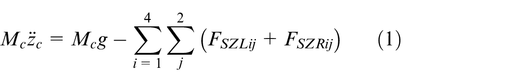
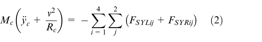
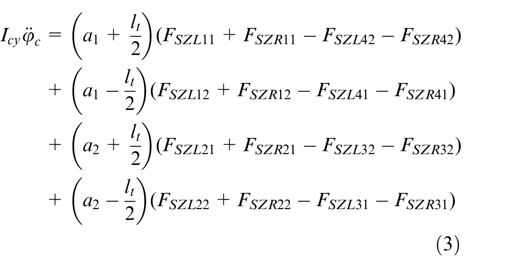
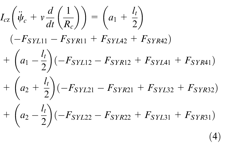
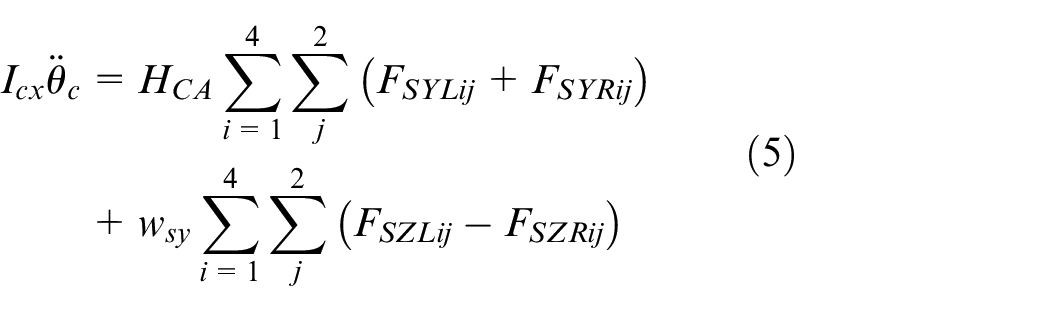
The differential equations of the vertical, lateral, nodding, shaking and rolling motions of the carbody are
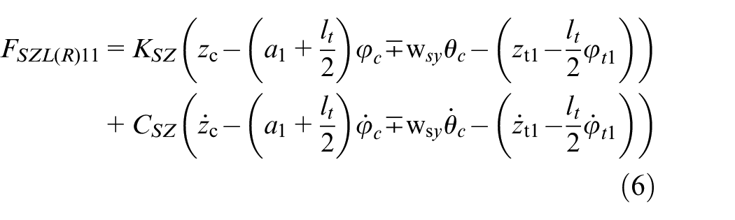
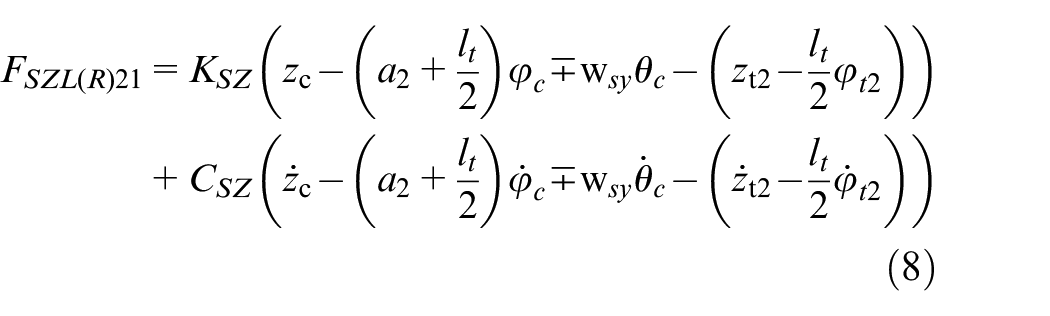
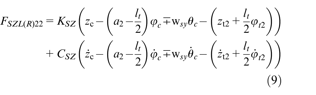
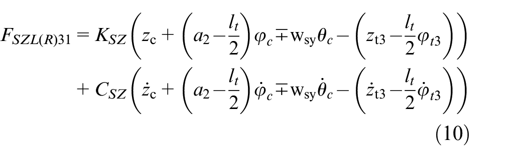
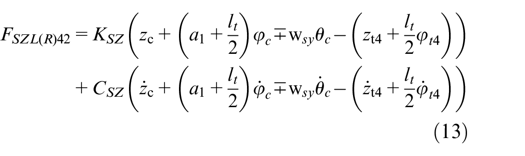
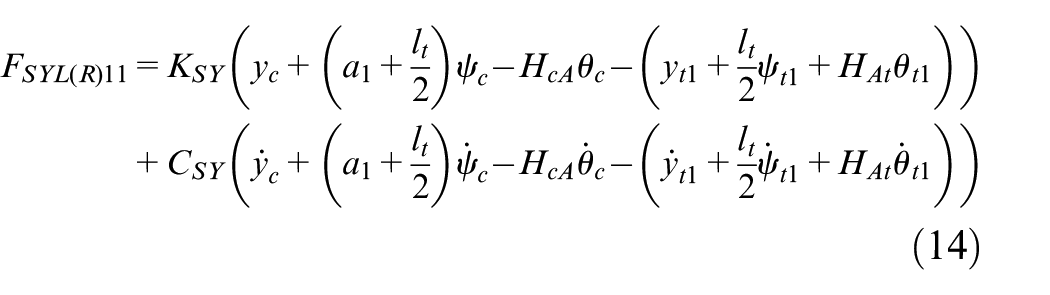
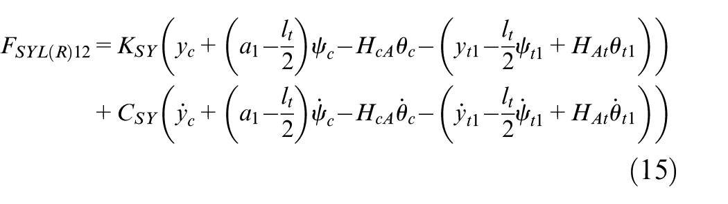
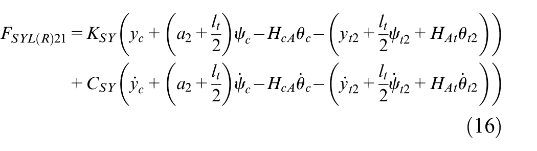
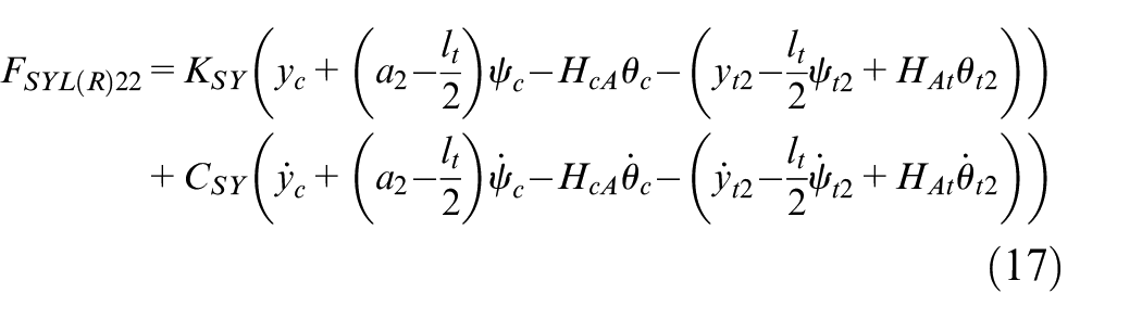
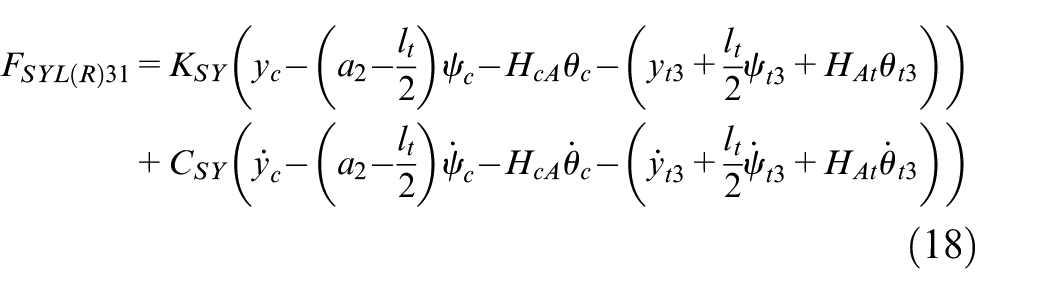
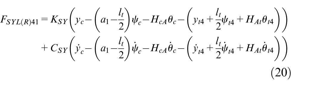
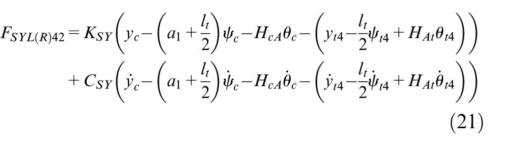
The vertical and lateral suspension forces of the secondary suspension system are


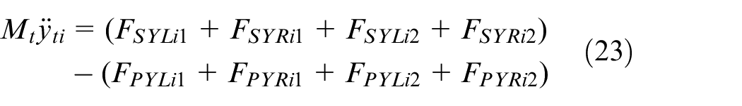
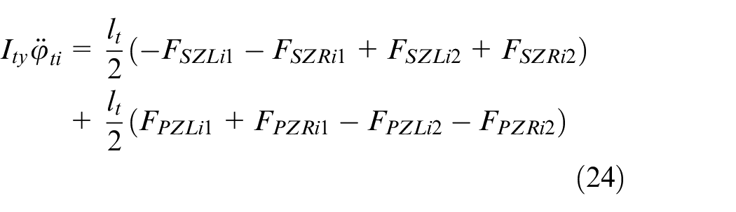
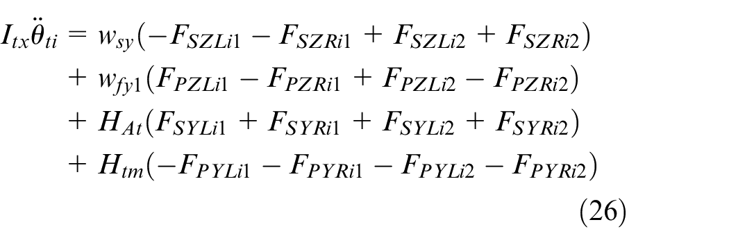
The differential equations of the vertical, lateral, nodding, shaking and rolling motions of the i-th bogie (
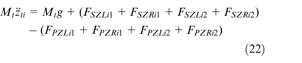

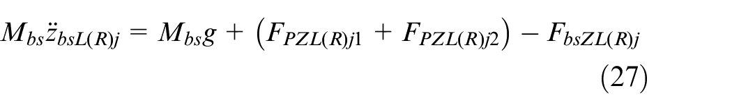
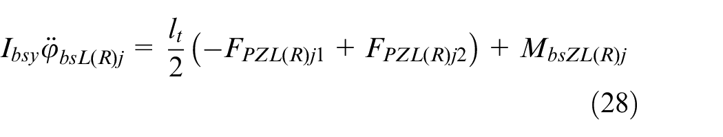
The differential equations of the vertical motion and nodding motion of the j-th suspension electromagnet (
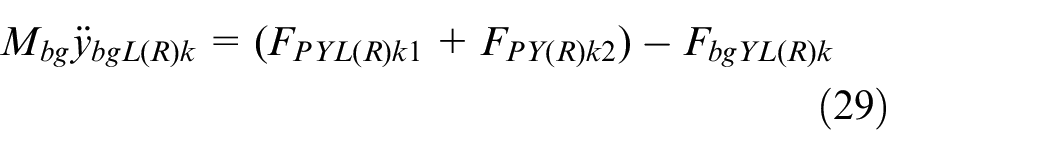
The differential equations of the lateral motion and shaking motion of the k-th guide electromagnet (

Coupling model of electromagnet
Based on the theory of electromagnetism, the coupling equations (including mechanical, electrical and correlation equations) for a single electromagnet, without taking into account magneto-resistance and leakage, are
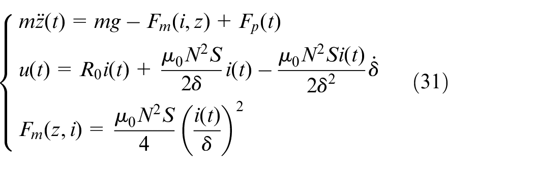
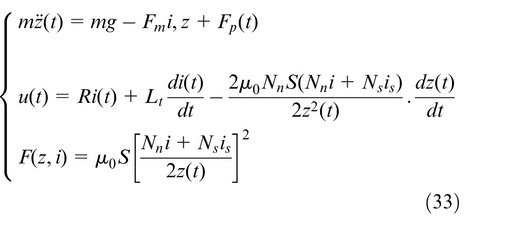
Two different hybrid models are also considered in this study: a hybrid magnetic suspension system made of electromagnet and permanent magnet (EMS + PM), and a hybrid magnetic suspension system made of electromagnet and superconducting magnet (EMS + SM). Figure 2 shows a hybrid suspension system consisting of an electromagnet and a permanent magnet (EMS + PM). The permanent magnet (PM) is mounted at the center of the U-shaped magnet. The coupling equations for the hybrid system consisting of a normal electromagnet and a permanent magnet (EMS + PM) are
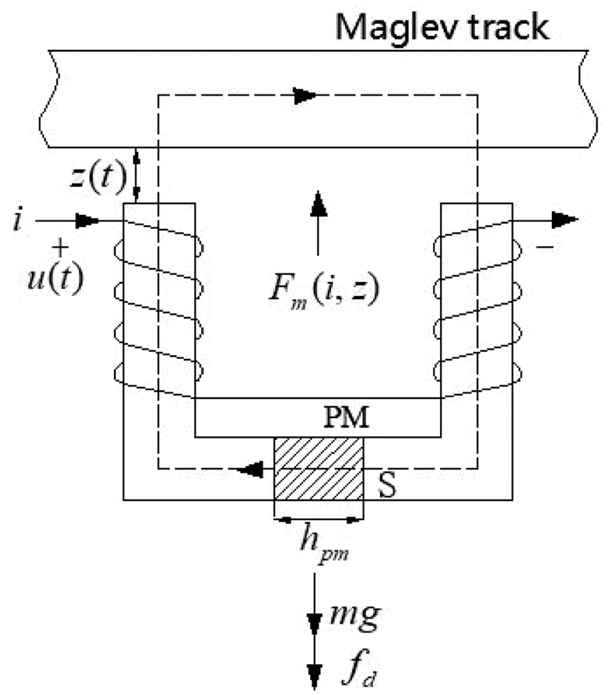
A hybrid magnetic suspension system consisting of an electromagnet and a permanent magnet (EMS + PM).
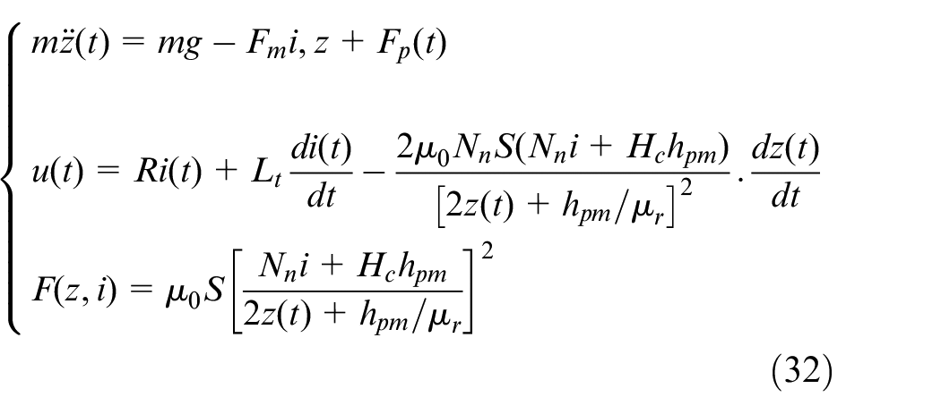
Figure 3 shows a hybrid suspension system consisting of a normal electromagnet and a superconductor electromagnet (EMS + SM). The superconductor coil is mounted at the center of the normal electromagnet, providing a static electromagnetic force. The magnetic potential generated by the superconductor coil and the coil of normal electromagnet are superimposed in the same direction. The coupling equations for the hybrid system consisting of a normal electromagnet and a superconductor electromagnet (EMS + SM) are
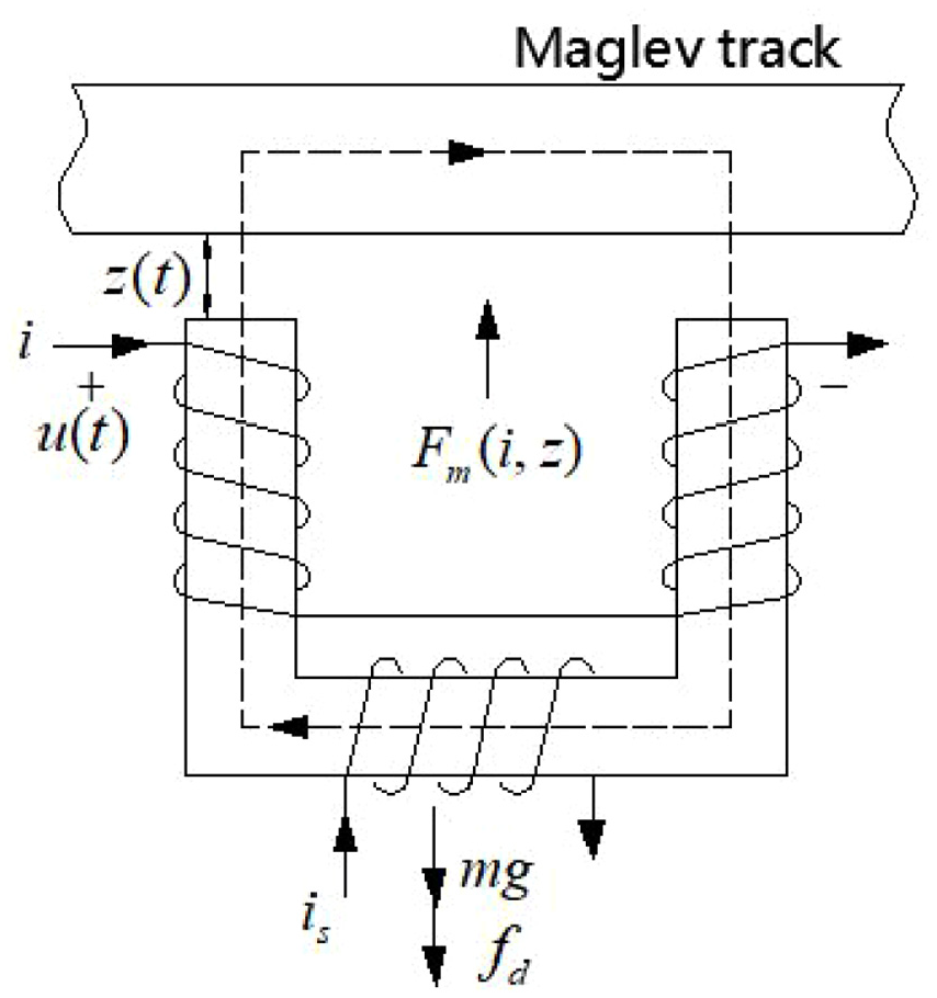
A hybrid suspension system consisting of a normal electromagnet and a superconductor electromagnet (EMS + SM).
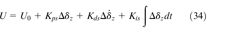
The classical two-stage series control strategy 35 is adopted for the control system of the suspension magnet, enabling the high-speed current loop to closely track the control voltage. The control voltage is affected by the gap signal collected by sensors at both ends of the suspension block. Assuming that the electromagnetic control circuit is in an ideal state, the PID control model of the suspension electromagnet is
Where
The classical two-stage series control strategy is also applied for the guide electromagnet controller. The current loop can quickly track the change of control voltage, and the position loop can quickly adjust the gap difference between the left and right guide magnets. The structure of the current control loop is shown in Figure 4.
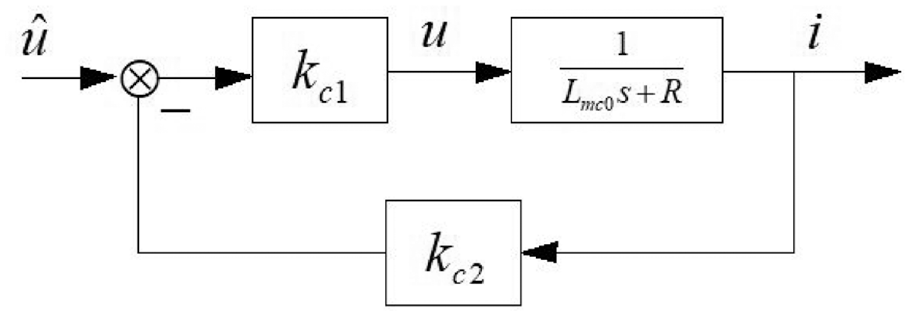
The model of current control loop.
The closed-loop transfer function of the current loop is
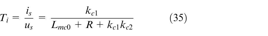
The gain of the model is
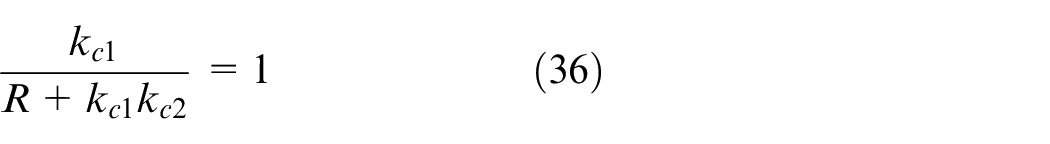
The control equation for the four control units of the k-th pair of guide electromagnets is
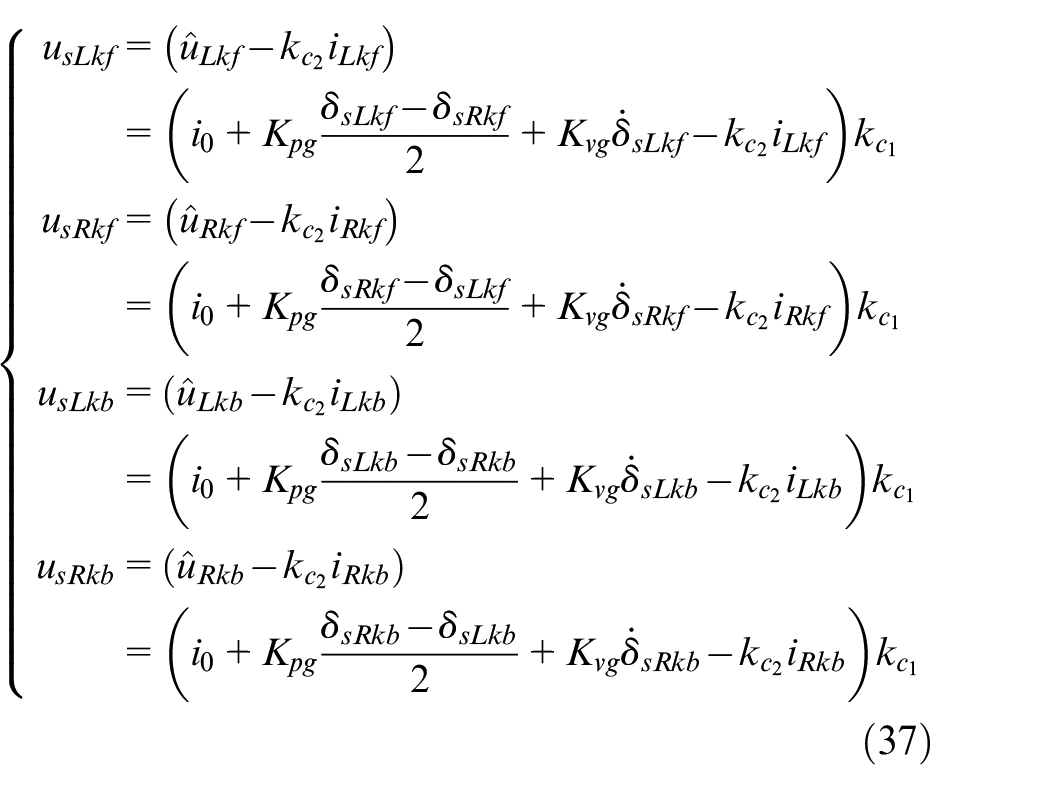
Where
Numerical calculation method and parameters
The solution for the above nonlinear coupled equations generally includes direct integration methods such as the Newmark method, the Runge Kutta method and the Wilson
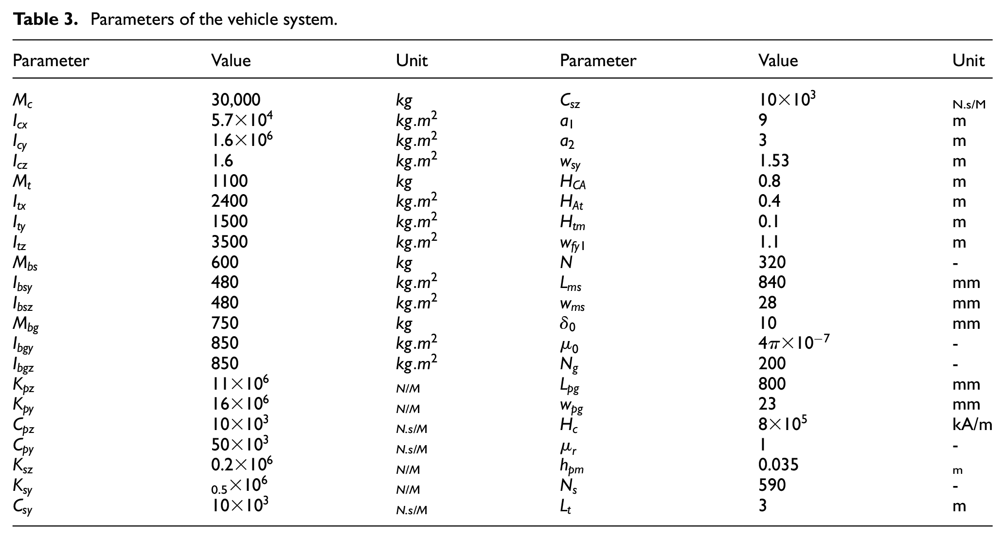
Parameters of the vehicle system.
Comprehensive Degree of Nonlinearity of Maglev train
Definition of Comprehensive Degree of nonlinearity
The nonlinear degree of a single vibration signal can be quantified by calculating the frequency deviation (between the instantaneous frequency and the local mean frequency) and the relative amplitude variation (between the instantaneous amplitude and the local mean amplitude) of the vibration signal, that is, the Degree of Nonlinearity (DN) 33 of a single vibration signal can be defined as the standard deviation of the frequency deviation and the relative amplitude variation.
Where
Where
The GZC local mean amplitude at each point along the time axis is defined as
where
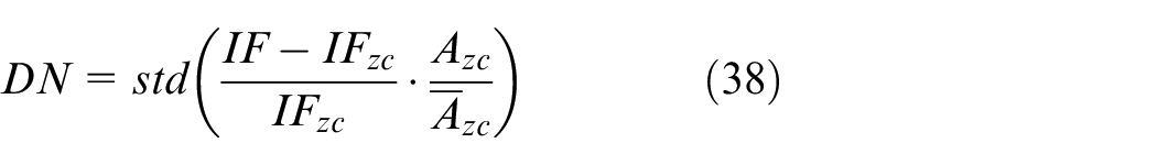
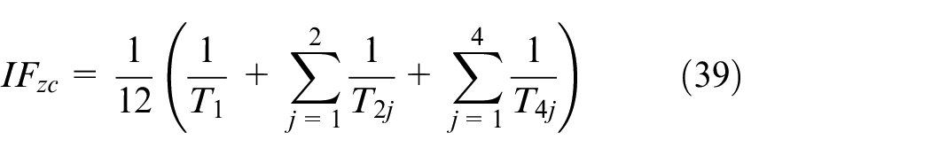
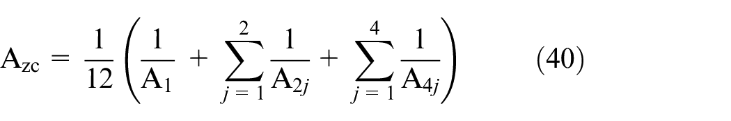
However, the DN can only give the nonlinearity of the vibration response of a single component, which is not suitable for direct application in the comprehensively assessment of the nonlinearity of the entire maglev train system. To solve this problem, the Comprehensive Degree of Nonlinearity (CDN), is proposed as
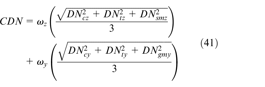
Where
Influence of electromagnet control parameters on the DN
The dynamic response of the vehicle system under harmonic track excitation is obtained by numerical simulation of the model described in Section 2, and then the DN of the vibration response is obtained applying the method in Section 3.1. This section explores the variation of the DN of vehicle’s vibration response and system stability with the control parameters of the suspension (guide) magnet.
Assuming that the maglev train runs on a straight line with vertical harmonic irregularity, with a wavelength of 32 m and an amplitude of 1 mm. When the maglev train runs on this track at 600 km/h, the DNs of vertical vibration response of the carbody, bogie and suspension magnet vary with
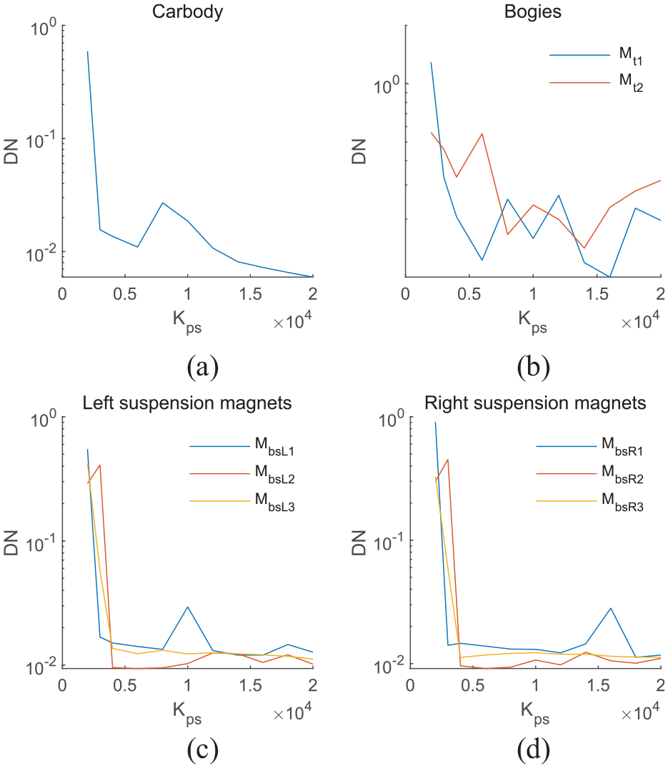
DNs for vertical vibration response of the carbody, bogie and suspension magnet corresponding to
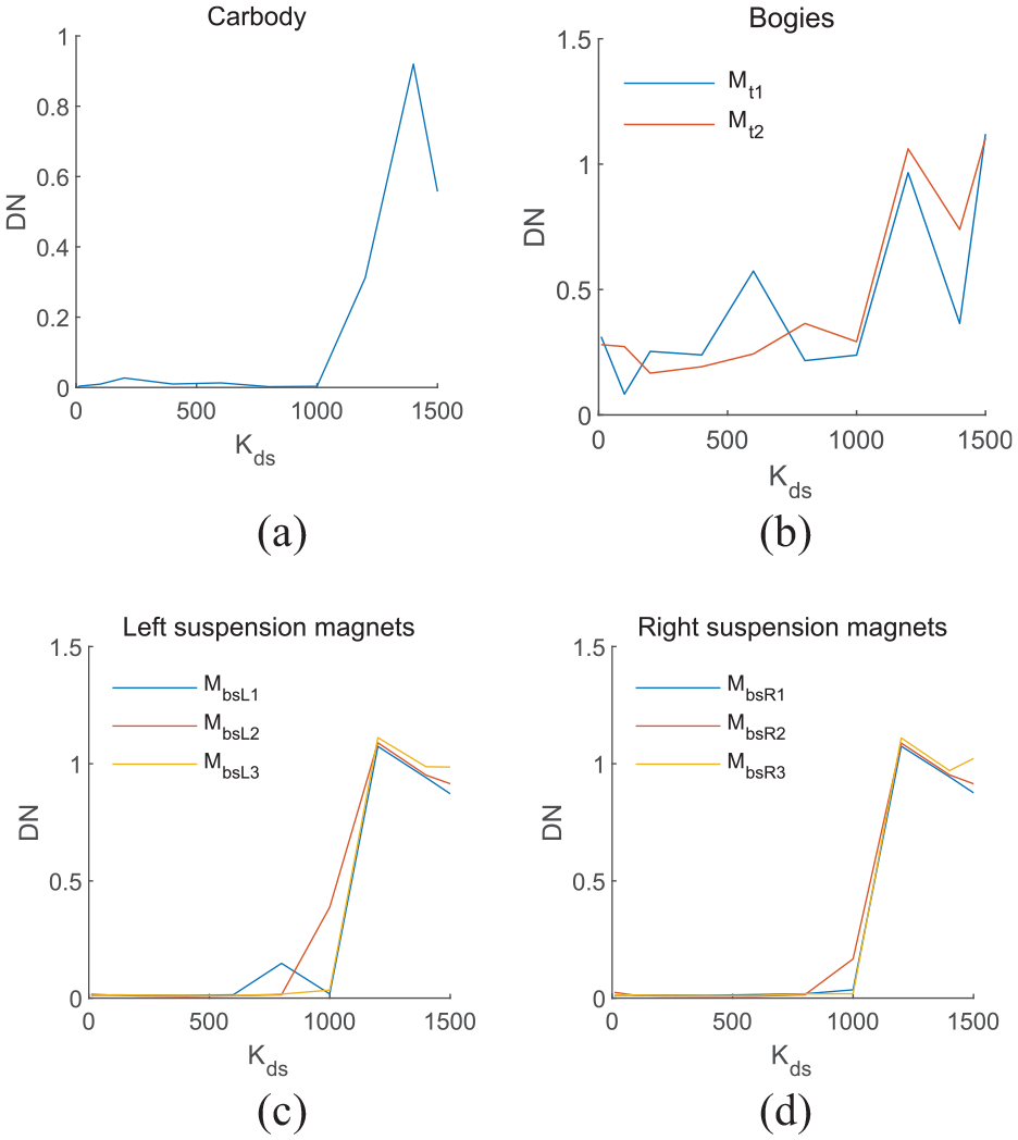
DNs for vertical vibration response of the carbody, bogie and suspension magnet corresponding to
Assuming that the maglev train runs on a straight line with lateral harmonic irregularity, with a wavelength of 32 m and an amplitude of 1 mm. When the maglev train runs on this track at 600 km/h, the DNs of lateral vibration response of the carbody, bogie and guide magnet vary with
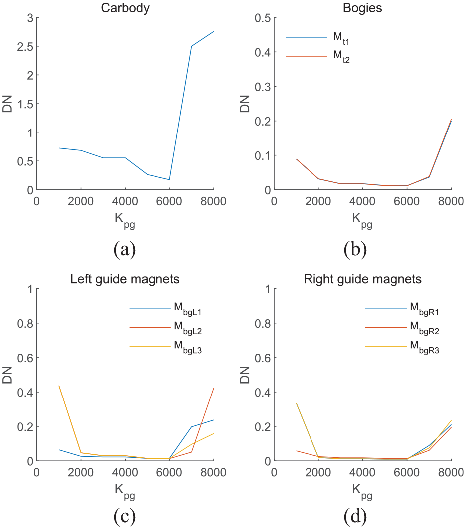
DNs of lateral vibration response of the carbody, bogie and guide magnet corresponding to
The DNs of lateral vibration of the bogie and guide magnet varies with
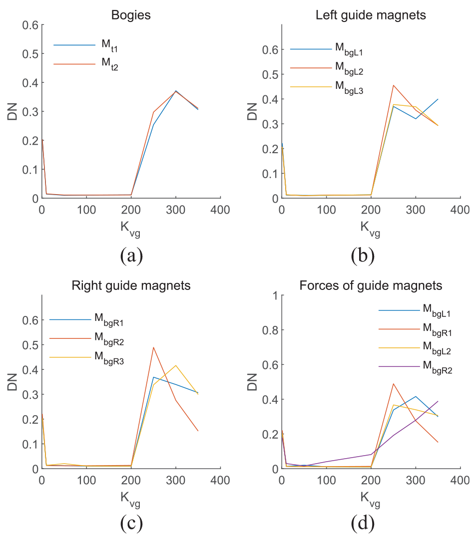
DNs for lateral vibration response of the bogie, guide magnets and guiding forces corresponding to
When the maglev train runs on this track at 600 km/h, DNs of lateral vibration of the bogie and guide magnet varies with
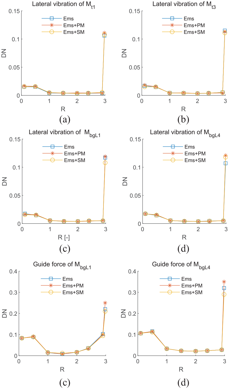
DNs of lateral vibration of the bogie and guide magnet corresponding to R.
When
Influence of harmonic irregularity of maglev track on DN and CDN
Assuming that the maglev train runs on a straight line with vertical harmonic irregularity in the wavelength range of 10–200 m and amplitude range of 1–5 mm. Three different combinations of suspension magnets mentioned in Section 2.2 are considered: electromagnetic suspension (EMS), a hybrid magnetic suspension system composed of electromagnet and permanent magnet (EMS + PM), and a hybrid magnetic suspension system composed of electromagnet and superconducting magnet (EMS + SM). The dynamic response of the vehicle system under harmonic track excitation is obtained by numerical simulation, and then the DN and the CDN of the vibration response are obtained by using the method described in Section 3.1.
When the train runs at the track at a constant speed of 600 km/h, the DNs of vertical vibration response of carbody, bogie and suspension magnet vary with wavelength and amplitude, as shown in Figure 10. Overall, the DNs of vehicle system vibration responses increase with the increase of wavelength. In the wavelength range of 10–100 m, there is a small increase in the DN for vertical vibration of the carbody, but the DN for vertical vibration of the suspension magnet gradually increases to 0.2, and the DN of vertical vibration of the bogie increases rapidly to 0.5. In the wavelength range of 100–200 m, the DNs of vertical vibration of carbody and suspension magnet reach 0.2, the DN for vertical vibration of the bogie fluctuates around 0.5. Under the excitation of long wavelength harmonic irregularity, the vibration response of the maglev vehicle system is strongly nonlinear. There is no significant change in the DNs of vibration acceleration of the carbody and bogie with increasing amplitude of harmonic irregularity, but the DNs of the vibration acceleration of the suspension magnet and suspension force increase slowly with the increase of the amplitude. The effect of the amplitude on the DN of vibration response is less than that of the wavelength.
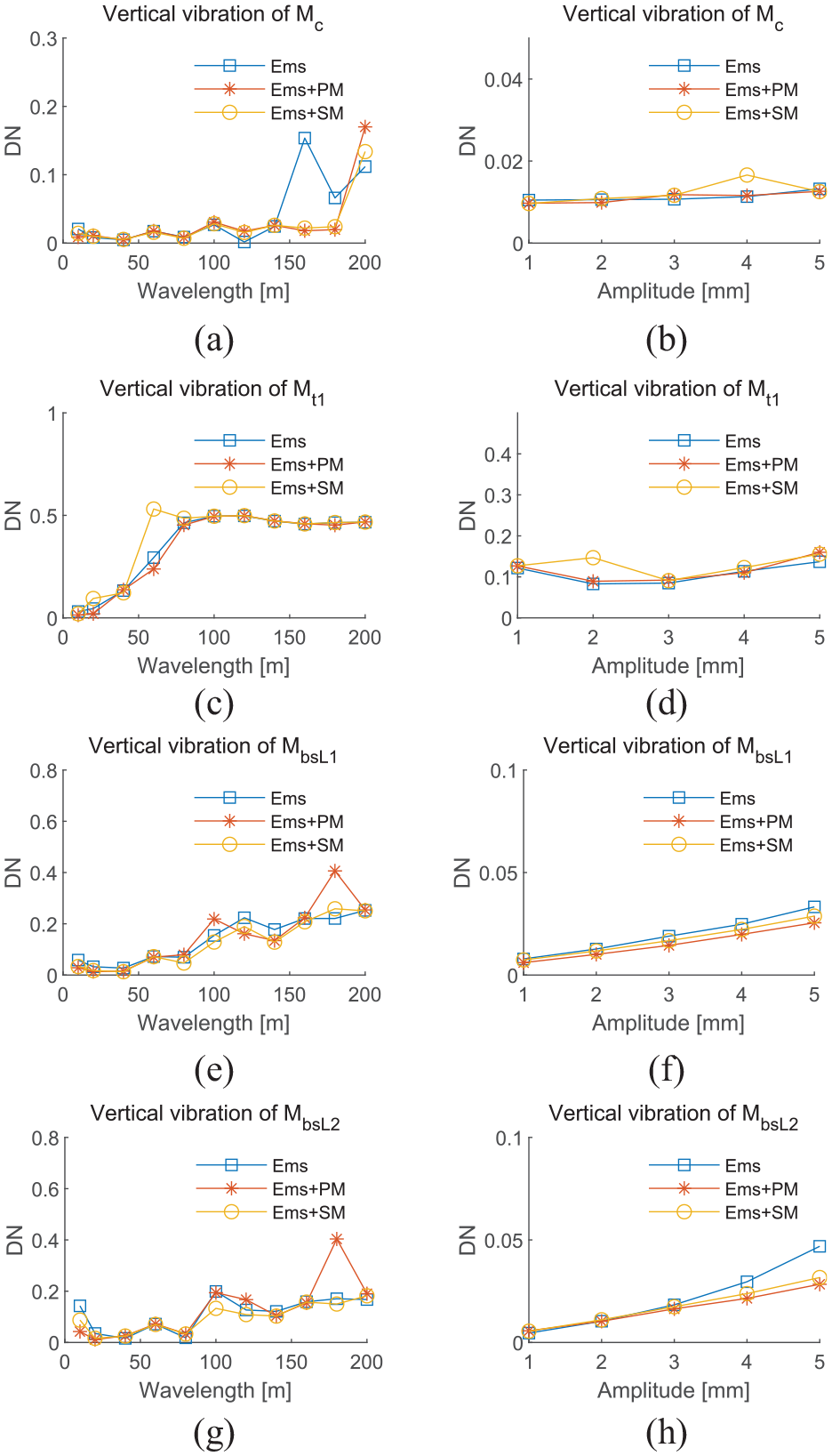
DNs of vertical vibration response of carbody, bogie and suspension magnet corresponding to vertical harmonic irregularity.
Figure 11 shows the CDNs of vehicle system corresponding to different wavelengths and amplitudes of harmonic track irregularity. When the wavelength is less than 50 m, the CDN is less than 0.1, and the vehicle system exhibits a small degree of nonlinearity. When the wavelength is greater than 50 m but less than 120 m, the CDN rapidly increases to nearly 0.2. In the wavelength range of 120–200 m, the CDN fluctuates around 0.2, and the vehicle system exhibits a high degree of nonlinearity. In addition, CDN increases gradually with the increase of amplitude. When the amplitude is 1 mm, the CDN is near 0.05, and the system vibration is almost linear. When the amplitude reaches 5 mm, the CDN exceeds 0.1, indicating a high degree of nonlinearity.
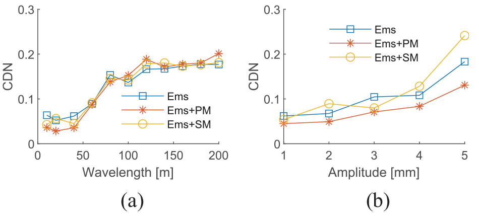
CDNs of vehicle system corresponding to vertical harmonic irregularity.
Finally, assuming that the maglev train runs on a straight line with both vertical and lateral harmonic irregularities, with a wavelength range of 10–200 m and an amplitude of 1 mm. When the train passes through the track at a constant speed of 600 km/h, DNs of vibration response of carbody, bogie, suspension magnet & guide magnet and CDN of vehicle system corresponding to different wavelengths are shown in Figure 12. DNs of vertical vibration of vehicle body, bogie and suspension magnet and the DN of lateral vibration of carbody increase with the increase of wavelength, but the DNs of lateral vibration of the bogie and guide magnet tend to decrease slightly. The CDN in Figure 12(g) shows that the CDN of the vehicle system’s vibration response generally increases with the increase of wavelength. When the wavelength is greater than 120 m, the CDN rapidly increases to around 0.2, indicating a high degree of nonlinearity. As the CDN of the response will inevitably increase when the stability of the vehicle system deteriorates, the long-wavelength harmonic irregularity is not conducive to maintaining the stability of the vehicle system.
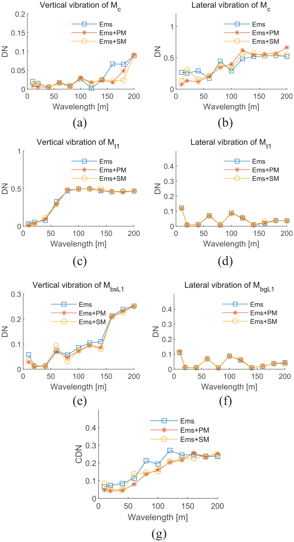
DNs and CDN of vehicle system corresponding to vertical and lateral harmonic irregularities.
Conclusion
The problem of how to qualify and evaluate the nonlinearity of the dynamic response of a maglev train system is studied by means of modeling and simulation. Based on the theory of the Degree of Nonlinearity (DN) of the vibration response of individual components, the Comprehensive Degree of Nonlinearity (CDN) of the vibration of the entire maglev train system is proposed and defined by incorporating the vertical and lateral vibration DNs of key components. While the DN proposed by the existing studies32–34 can only reflect the DN and stability of a single component in a single direction, the CDN proposed in this study is specifically designed for maglev trains and can reflect the degree of vibration nonlinearity of the entire maglev vehicle system. Through the analysis of the DNs and CDN of the vehicle’s vibration response, the following conclusions can be drawn: (1) The control parameters of the suspension and guide magnets not only determine the stability of the vehicle system, but also affect the DN, (2) Given that the DN and CDN can effectively reflect the change trend of system instability, they can be applied for safety monitoring and prediction on maglev trains, and (3) When the CDN is greater than 0.1 or even exceeds 0.2, the vibration of the vehicle system may be unstable and high attention is required.
Footnotes
Declaration of conflicting interests
The author declared no potential conflicts of interest with respect to the research, authorship, and/or publication of this article.
Funding
The author disclosed receipt of the following financial support for the research, authorship, and/or publication of this article: This work was supported by the scientific and technological project in Jiangsu Province, China (Grant No. FZ20210428) and the scientific and technological project in Sichuan Province, China (Grant No. 22ZDYF3092).
Data availability statement
Data sharing not applicable to this article as no datasets were generated or analyzed during the current study.