
Abstract
This paper proposes a new geometric control method for homography-based visual servo control of Underactuated UAVs. In order to solve the application difficulties of geometric control in HBVS and explore a visual servo control technology that can be applied to aerial detection operations, this paper integrates the geometric control into the visual servoing framework and design a new homography-based geometric visual servoing controller. The outer loop is used as feedback information using the virtual homography matrix between the two images. The inner loop controls the orientation of the UAVs through geometric control. The stability of the proposed controller is proved based on Lyapunov’s theory. The proposed method has better transient performance and dynamic performance than the conventional visual servo method. The excellent performance of the controller has been proven by a large number of experiments. In addition, the application of the controller on an unmanned aerial manipulator is demonstrated.
Introduction
Unmanned aerial vehicles (UAVs) are widely used in both civilian and military applications because UAVs can perform some dangerous tasks instead of humans. 1 In many applications, a degree of autonomy for the UAV is a guarantee of mission accomplishment. Normally, UAVs can accomplish most of their missions through GPS and IMU, 2 but relying solely on these sensors cannot obtain position information relative to local targets, making it impossible to complete tasks that require local information, such as inspection and manipulation. UAVs can perform many tasks through visual servo control, such as target tracking,3,4 target search, 5 autonomous landing, 6 etc.
In the current study, most researchers tend to use the image-based visual servo (IBVS) to design controllers.7,8 IBVS uses only image information to extract feature points for feedback control, which is not very demanding on the camera and easy to implement in practice. In, 9 the visual dynamic equation of point features is constructed under the spherical projection model, and the nonlinear controller is constructed and designed by using the backstepping method. A controller design method based on circular features is proposed to estimate the relative position and attitude of the target by analyzing the model of spherical features for control design. 10 Dynamical with point features is considered and subsequent controller design is performed. 11 In the above method, points, lines and other features in the image are used in the design and only part of the information in the image is used, which requires that the features should always remain in the field of view during the motion.
There is another type of visual servo control that uses the Homography matrix as the image feature for controller design, called Homography-based visual serving (HBVS).12,13 When there is an overlap between two images, the Homography matrix can be calculated in several ways. The homography matrix contains parameters such as rotation matrix, displacement, and normal vector, and decoupling these geometric parameters is difficult. Currently, HBVS is often used in industrial manipulator or full actuated system. A new homography-based visual tracking method is proposed and global stability was demonstrated. 14 The underwater robot applied only vision sensors, calculated the homology matrix and used the homography matrix as a feedback feature. 15 Motivated by the Backstepping method and Lyapunov theory, an adaptive controller of unknown depth was constructed using a homography matrix. 16 Using the homography matrix to control underactuated UAVs is a challenging task. Author defined a new virtual homography matrix based on the backstepping method to design the controller, 17 but the yaw angle control was independent of the position in the control design, which meant that the yaw angle needed to be stabilized quickly before the whole could be stabilized. Huang et al. proposed a servo control method based on homography for tracking a six degree of freedom moving ship using a rotary wing drone. The feature points of the moving target were measured using a monocular camera and the projection mapping transformation between the target and the drone was calculated. Next, based on these transformations, the tracking error is converted into pose error, and a controller is designed to control the rotor drone. 18 Zheng et al. proposed an image-based dynamic visual servo control method for the positioning and control of unmanned aerial vehicles. By solving the homography matrix to reconstruct the pose and integrating it into the controller design, it has good real-time performance and robustness, and can be applied to unmanned aerial vehicle control applications in complex environments. This method usually requires operations such as singular value decomposition of the homography matrix to calculate the position and attitude, which increases the computational workload of the onboard processor. 8 In recent years, a new type of controller has emerged for use in underactuated UAVs, called the geometry controller. The application of geometric control in UAVs attitude control has good effects, as it can overcome modeling errors and external disturbances, improve the stability and robustness of the control system, and have fast response control capabilities. It was first proposed for the problem of tracking the attitude of a fully actuated rigid body at a point. 19 Later, the geometric controller continued to be developed and was used in underactuated UAVs, 20 using position information as a feedback feature and proposing a control method with global stability. A geometric L1 adaptation method to estimate uncertainty was demonstrated and enabled better robustness of UAVs. 21 The above is mainly position-based servo control, but since homography-based dynamics is different from position-based dynamics, extending the geometric controller to HBVS is a challenging task. For example, in homography-based visual servo control, it is a challenge to associate visual features and homography estimation results with the controller, and design effective controllers to accurately respond to changes in homography matrix and stably control attitude. However, by extending geometric control to visual servo control based on homography matrix, we can not only leverage the advantages of geometric control in attitude control in HBVS, but also expand the field of visual servo.
Influence of unmodeled dynamic factors
In Ref., 22 the author designed a hybrid framework of opportunity reinforcement learning and deep learning to avoid the impact of frequent changes in the autopilot system, and replaced traditional electronic flight controllers with 3D gestures. This method is different from most methods and has strong novelty. The author proposes a linear extended observer and a sliding mode control method based on dual loop one-dimensional fuzzy control to ensure stability of the quadcopter unmanned aerial vehicle, which belongs to nonlinear and underactuated systems and introduces dynamic factors and uncertainties for modeling. This method uses an observer to ensure the stability of the system. 23 In Ref., 24 the author proposes an adaptive robust control algorithm to address the issues of instability and low convergence rate caused by unmodeled dynamic factors in quadcopter unmanned aerial vehicles. The author did not use an observer, but it can also ensure the stability of the system. In Ref., 25 the author proposes a dual loop one-dimensional fuzzy sliding mode control (DLSDF-SMC) to improve the performance of spiral trajectory tracking, and proposes a state feedback controller composed of a position estimator and a disturbance observer design for unmodeled dynamic factors. The author proposed various observer and control design methods, evaluated the performance of underactuated quadcopter unmanned aerial vehicle dynamics models based on Newton Euler equations and quaternions, and verified that using quaternion mathematical models can be applicable to various observer designs and adapt to unmodeled dynamic factors. 26 In Ref., 27 the author proposes a model-free one-dimensional fuzzy sliding mode control (MFSDF-SMC) to control the attitude and position of underactuated quadcopter drones, addressing the problem of difficult control caused by unmodeled dynamic factors and uncertainties. In Ref., 28 the author extensively reviewed several hybrid observer design methods and new control strategies to address the difficulty of addressing unmodeled dynamic factors in various flight modes of underactuated quadcopter aircraft. In Ref., 29 the author described the hybrid control design of underactuated four rotor systems without modeling dynamic factors. The author conducted performance analysis on fuzzy based sliding mode control and one-dimensional fuzzy sliding mode control methods in underactuated four rotor unmanned aerial vehicles, and designed a single input fuzzy sliding mode control method. 30
From the above literature, it can be seen that underactuated multirotor UAVs have the influence of unmodeled dynamic factors on control stability. Therefore, many researchers have designed algorithms or observers based on fuzzy sliding mode control to address the stability challenges brought by unmodeled dynamic factors. Some researchers have solved the problems caused by unmodeled dynamic factors by designing adaptive control methods, robust control methods, and reinforcement learning. In addition, inversion control can also solve the problems caused by unmodeled dynamic factors. In this paper, to address this issue, this paper introduces backstepping control method to enhance the robustness and adaptability of underactuated multi rotor UAVs to unmodeled dynamic factors, without using methods such as designing observers. Specifically, this paper defines a new velocity error based on inversion control technology to design visual dynamics equations to address the impact of unmodeled dynamics factors, as detailed in the following text.
Compared with the existing HBVS solutions, our contributions of this paper are summarized as follows: (1) The proposed method establishes the visual dynamics equations based on the homography matrix between two images. Different from the conventional IBVS,9–11 the homography-based architecture allows the UAV to work with a small field of view. (2) A new geometric control method for homography-based visual servo control of Underactuated UAVs is proposed. Compared to other controllers,15,16 geometric controller has better results for UAV attitude control. In addition, geometric control method can overcome modeling errors and external disturbances, improve the stability and robustness of the control system, and have fast response control capabilities. Therefore, extending geometric control to visual servo control based on homography matrix not only ensures the stability and accuracy of posture in HBVS, but also extends geometric control in the field of visual servo control based on homography matrix. A stability analysis of the closed-loop system is performed and proved using Lyapunov. The final experimental results also demonstrate the excellent dynamic performance of the proposed method. (3) To demonstrate the broad applicability and robustness of the proposed method, this paper applied it to the unmanned aerial manipulator.
The paper is organized into six sections. The notation and the dynamics of UAV are mentioned in Section II. A definition of virtual homography matrix and problem formulation is given in Section III. A new geometric approach for homography-based visual servo Control of underactuated UAVs is present in Section IV. This paper shows the experimental results in Section V and draw conclusions in Section VI.
Preliminary background
Notation
Let us consider the UAV equipped with the vision suite. Assuming that the camera frame overlaps with the UAV frame, 11 it can usually be solved by using an external method to obtain the transformation between the body frame and the camera frame. The following notation are used throughout the article:
Let
As shown in Figure 1, let
The Euler angles relative to the reference frame are expressed as
The operator
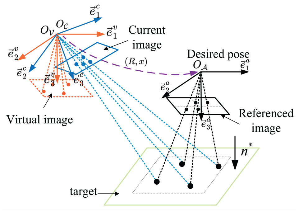
Geometric relationship of each frame.
Dynamics of UAVs
UAV is assumed as a symmetric quadrotor model. Based on the previous literature, 31 the dynamics are


where
Visual dynamics
Image features and dynamics
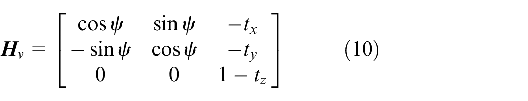
The control objective is to stabilize the UAV’s pose to the desired pose based on the current image and the reference image. This paper assumes that there is a good homography matrix estimate for the control design. This paper selects the homography matrix
where
The pitch angle
This paper solves for the derivative of equation (8) as follows
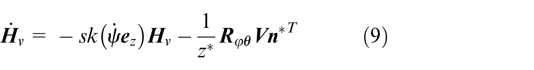
where
Under assumption 1, it can be known
Proof. Considering the virtual homography matrix (8) and
where
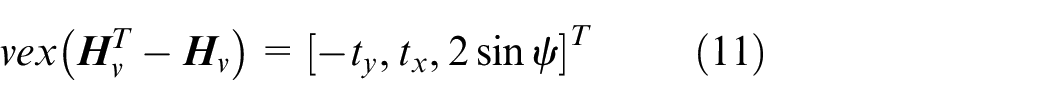
The yaw angle can be calculated by equation (11).
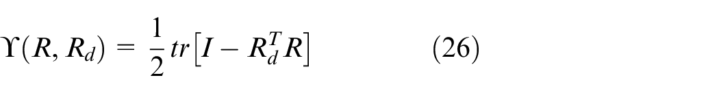
Problem formulation
According to the reference image in desired pose (the reference frame) and the current image captured using a down-looking monocular camera, the control goal is to stabilize the body pose of the UAV at the desired pose. Also, the control goal is to ensure that

where

where

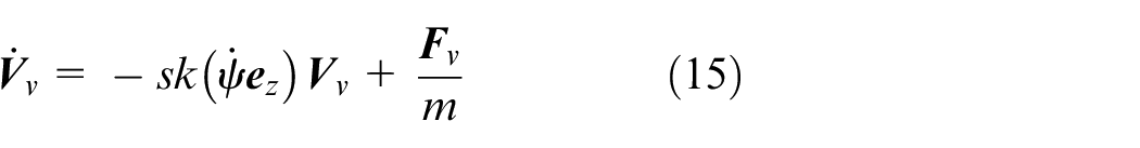
where
From (2), (4), (5), (14), (15), the control objective is to stabilize
HBVS control design
The structure of HBVS scheme is shown in Figure 2. The image-based outer loop generates the control thrust and the desired attitude, acts on the geometric attitude controller. The geometric attitude controller calculates the required torque.
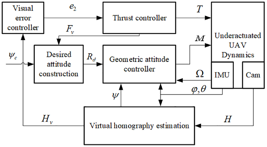
HBVS control structure.
Outer loop control
According to the backstepping technique, this paper defines a new velocity error

The following control law guarantees the visual errors

where
Proof. Considering the candidate Lyapunov function
By using (16), (17), the time derivative of (19) is obtained as
When the parameters
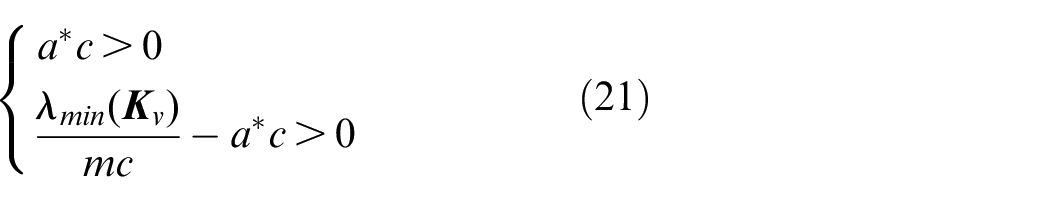
Accordingly, the visual errors
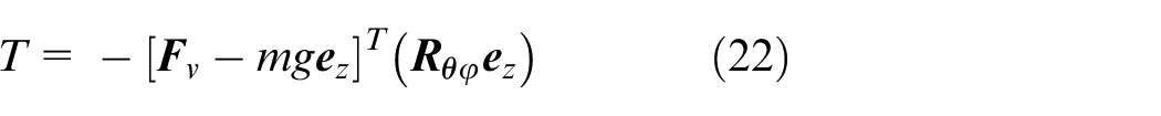
Then, according to the defined virtual control input (18) and model equation (4), the thrust
Geometric attitude controller
Given that the rotation matrix is continuously changing in the Lie group
where
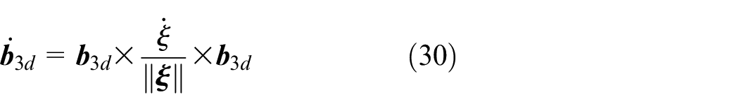
Based on practical experience and to avoid the attitude singularity problem, this paper assumes
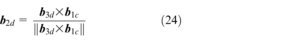

Then, the desired attitude
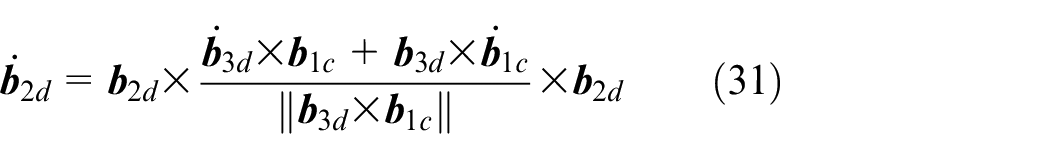
The time derivatives of

According to the proposed function


where

Considering the dynamic (5), (28) and (29), this paper designs a control input

where
Proof. Considering the candidate Lyapunov function
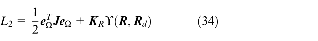
By using (5), (27), (29), the derivative of (34) is obtained as
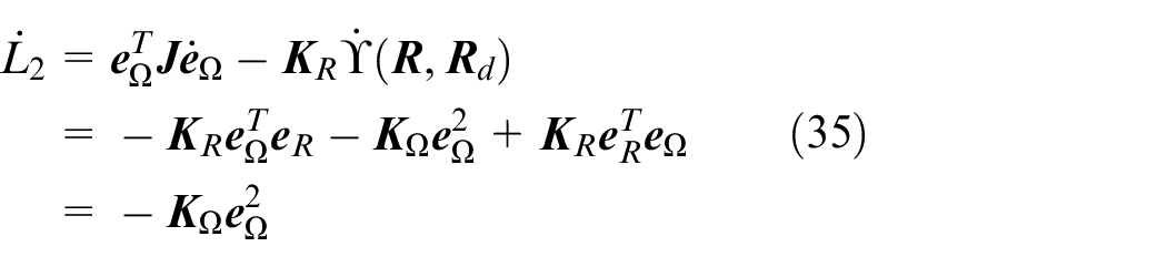
From equation (35), it can be known that
Experimental results
The proposed control method has been tested in kind with a quadrotor shown in Figure 3. The quadrotor we used was developed based on an existing quadrotor model (P-600) with a wheelbase of 600 mm. The total mass of the quadrotor is 3.3 kg. The quadrotor is equipped with a camera and an onboard computer. The camera is a monocular grayscale camera that provides image data in 640 × 480 size and is captured at 60 Hz. The size of this camera is 3 × 3 × 2 cm. The PIXHAWK autopilot is mounted on the quadrotor and obtains pitch, roll and angular velocity from the built-in inertial measurement unit (IMU) and exchanges data with the onboard computer via UART. An external motion capture system is used to obtain the true speed of the quadrotor. The brand of this external motion capture system is Optitrack, with a total of 12 cameras and a space size of 9 × 6 × 4 m. All code is programed in C++ and runs on a quadrotor onboard computer. The onboard computer runs the Robot Operating System (ROS) and sends control commands to the PIXHAWK autopilot. The outer loop control frequency depends on the image acquisition frequency and is 60 Hz. The frequency of the geometric attitude controller is set to 250 Hz. The diagonal axis distance of the quadrotor is 60 cm and other physical parameters are as follows:
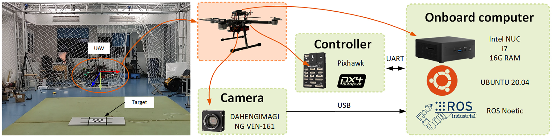
Experiment platform.
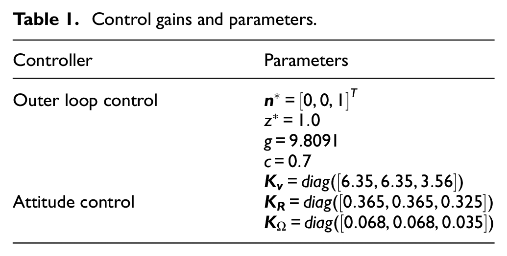
Control gains and parameters.
Performance testing
This experiment aims to demonstrate the superior performance of the above algorithm on a real UAV. The purpose of the experiment is to stabilize the UAV from the current position to the reference position. This paper sets up two common initial states, one with errors in position and the other with errors in attitude angle, and 15 experiments were conducted for both cases. Initial states are as follows: (1)
The whole experiment lasted for 10 s, and the results of the experiment are shown in Figures 4 to 7.
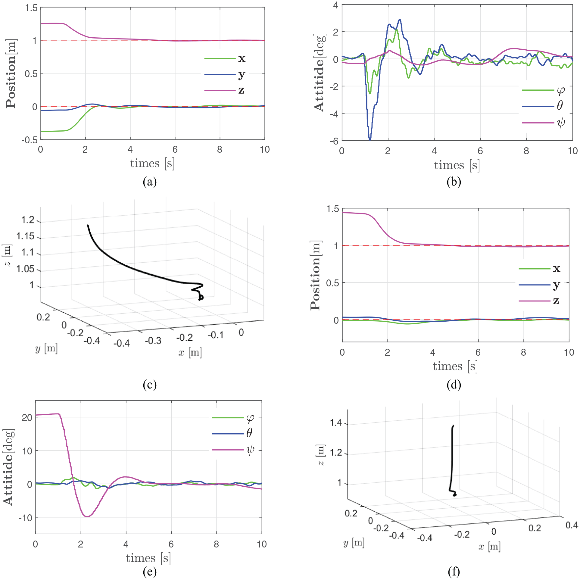
Experimental results of position and attitude of exp1 and exp2: (a) position of exp(1), (b) attitude of exp(1), (c) trajectory of exp(1), (d) position of exp(2), (e) attitude of exp(2), and (f) trajectory of exp(2).
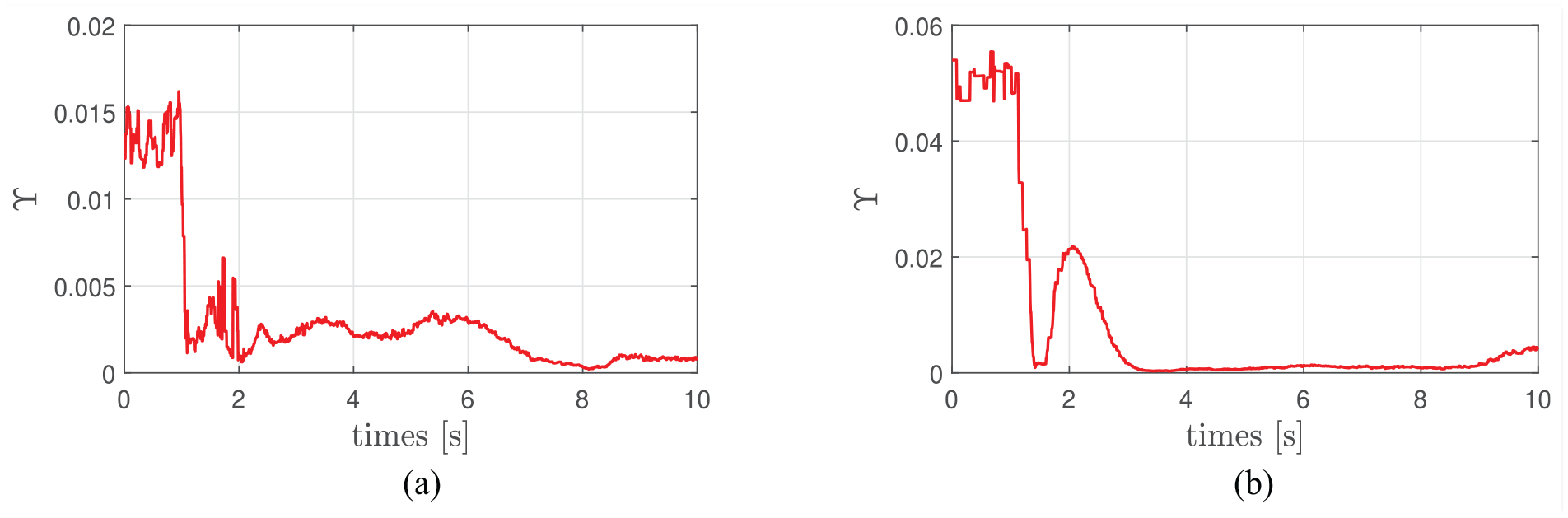
Attitude error function
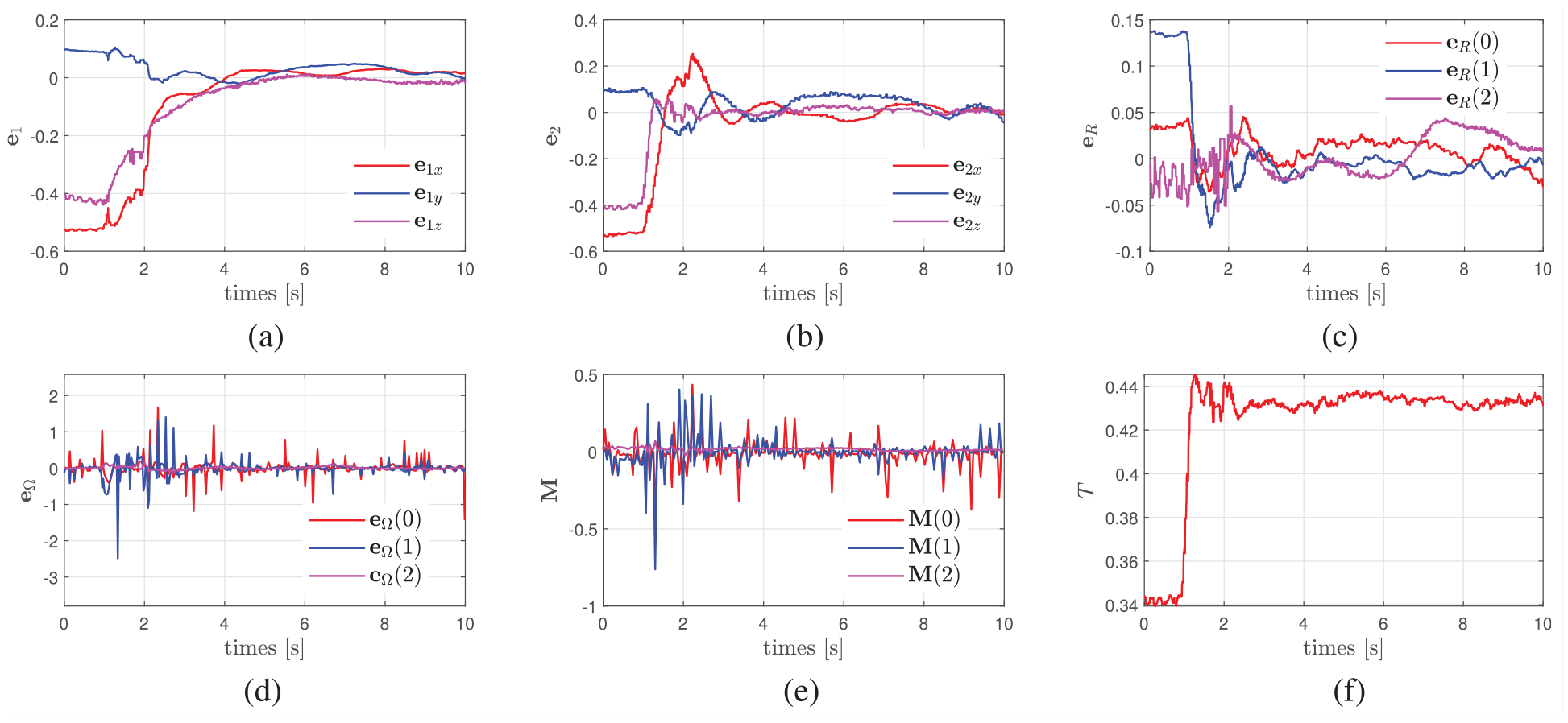
Experimental results with large position offsets (exp1): (a and b) visual error
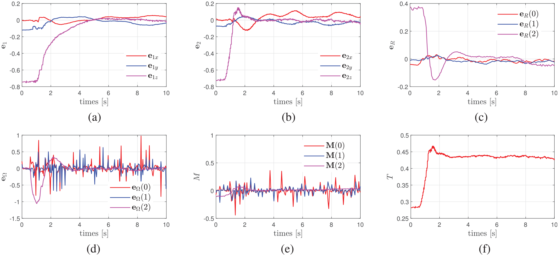
Experimental results with large yaw offsets (exp2): (a and b) visual error
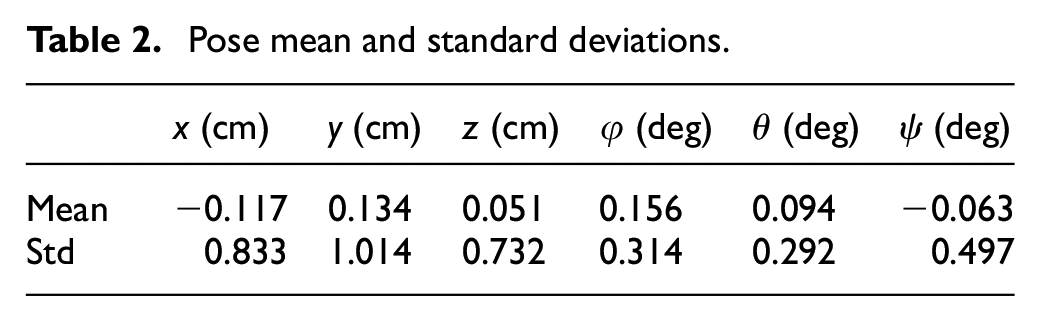
The UAV initiates offboard control mode flight at t = 1 s, after which it smoothly and quickly reaches the desired position at about t = 3 s shown in Figure 4. The entire process takes about 2 s. This indicates that the proposed method has excellent transient performance. It remains in a steady state for the time afterward. To show the excellent steady-state performance of the proposed method, this paper shows the mean, standard deviation of the position and attitude angles for all experiments in Table 2.
Pose mean and standard deviations.
In addition, this paper also provides the dynamics of all variables in the proposed method during the experiment shown in Figures 6 and 7. The graphs showing the evolution of the various errors metrics are very useful to understand how inner and outer loops of the system have different dynamics with different convergence rates and steady-state values.
The visual errors
After several experiments, it is proved that our proposed attitude control apparatus based on homography features has good control performance.
Application to a unmanned aerial manipulator
In terms of application, the controller we have designed can be widely used in the visual servo application control of various multirotor UAVs, as dynamics and geometric control are not limited. In application scenarios, our designed controller can be used for visual servo based contact detection tasks, such as bridge internal corrosion detection, fan blade crack detection, and oil and gas pipeline internal corrosion detection. In some complex outdoor environments, RTK can be used to provide more accurate location information, ensuring the robustness and adaptability of the system. Here, we apply our designed controller to detect the thickness of the target steel plate, a task similar to detecting the thickness of oil and gas pipelines. The system configuration is shown in Figure 8. This paper equips the UAV with a device to detect the thickness of steel plates and moved the camera to the front of the UAV. The desired position is
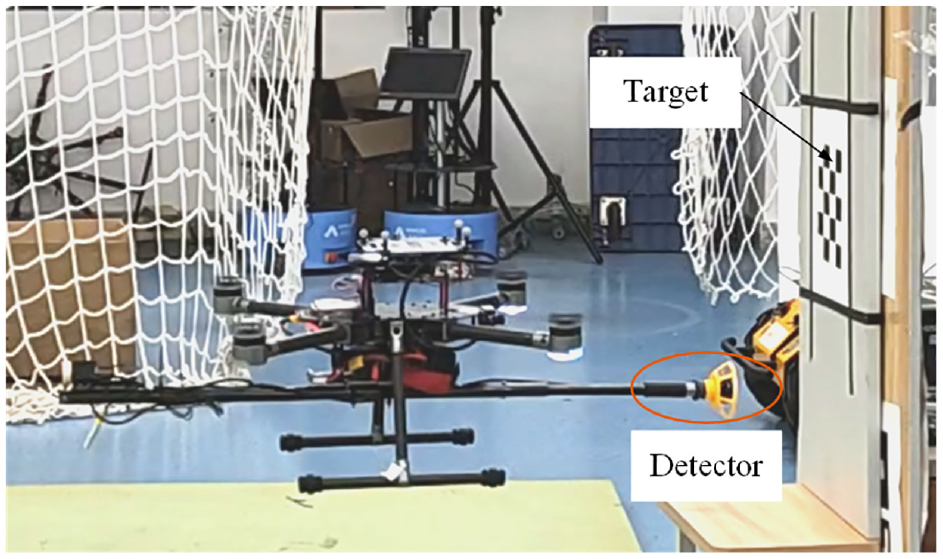
System configuration.
The corresponding results are shown in Figure 9(a) to (d). Under the action of the control torque and thrust, the UAV gradually reaches the desired position shown in Figure 9(a) and (b). Because this paper only verifies the effect of the controller mentioned in this paper, this paper does not consider the effect of the contact force between the UAV and the steel plate. When external contact forces exist
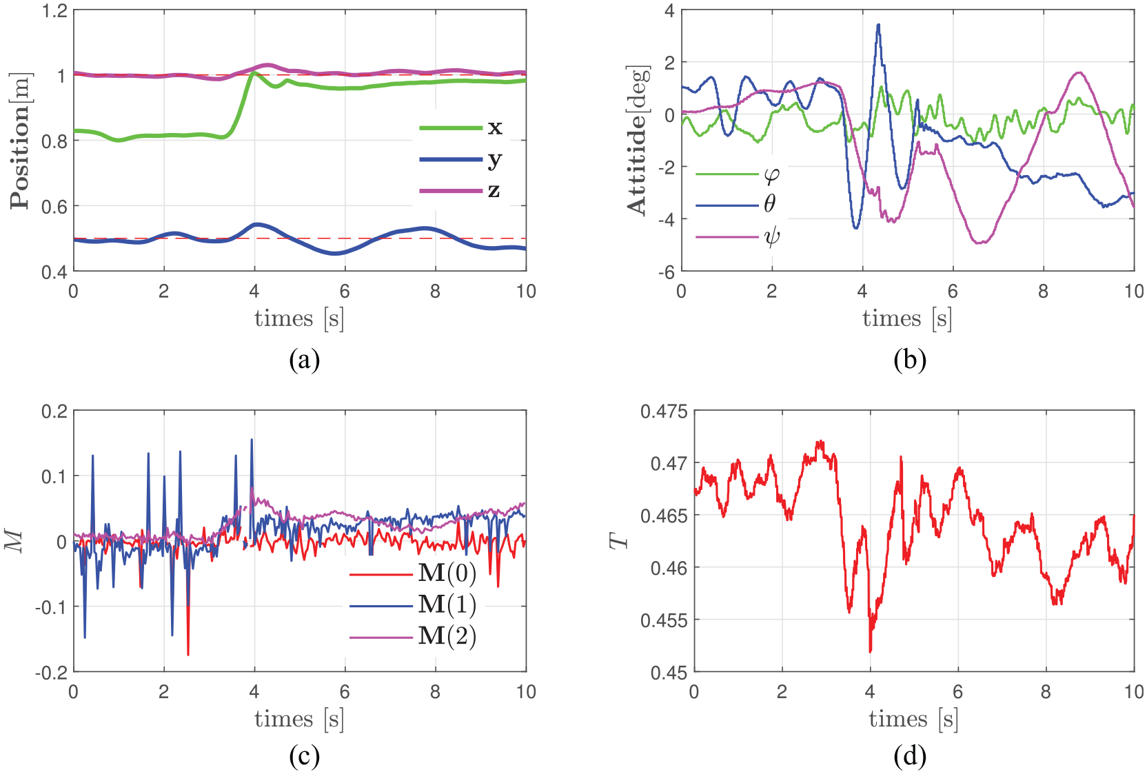
Experimental results of contact detection: (a) visual error
Conclusions
This paper proposed a new visual servo geometric control method for underactuated UAVs based on homography. The paper proposed the use of a virtual homography matrix for the backstepping-control of the visual position error and geometric-control of orientation. Among them, this paper used virtual homography to define visual position error, used visual position error to control the position and yaw angle of the drone, and then integrated the visual position error into the control law of the geometric method to achieve control of the UAV’s attitude. This paper used theoretical analysis and extensive experiments to verify the performance of our proposed control method. The experimental results showed that this method had good transient performance, dynamic performance, and robustness. This work had solved the challenges of geometric control methods in visual servo control based on homography, and expanded the field of visual servo, which was a new direction. The field of visual servo control has great prospects, whether in academic fields, industrial applications, or civilian consumer applications. Therefore, the field of visual servo control is worth further research, and we will continue to study this field, improve the application of geometric control in this field, and explore more efficient visual servo control methods.
Footnotes
Declaration of conflicting interests
The author(s) declared no potential conflicts of interest with respect to the research, authorship, and/or publication of this article.
Funding
The author(s) disclosed receipt of the following financial support for the research, authorship, and/or publication of this article: This work was supported by the National Natural Science Foundation of China under Grant No. (62103140, 62173132, 62133005), Natural Science Foundation of Hunan Province under Grant No. (2021JJ40124).
Data availability statement
Data sharing not applicable to this article as no datasets were generated or analyzed during the current study.