
Abstract
The probability of actuator lock, control surface damage, and thermal insulation failure on supersonic aircraft due to high speed and temperature is significant. Additionally, foldable fins are often used in missiles to increase the number of missiles that can be loaded onto a launcher and facilitate transportation, but this design presents the potential for malfunction and failure to open during flight. This study focuses on scenarios where control surfaces do not open or are partially damaged, leading to asymmetries and changes in the vehicle’s dynamics and aerodynamic model. The aim is to detect such failures and design a control system that can withstand these issues. To achieve this, the paper proposes an equivalent aerodynamic model representing the vehicle’s dynamics. The health of each fin is monitored using a nonlinear filter to estimate a parameter. Using separation theory, the dynamic system is divided into fast and slow subsystems, and a control signal for the faulty dynamics is designed based on back-stepping theory principles. Furthermore, the control allocation method is modified to accommodate the condition of the fins and generate the desired control moment. The proposed technique can quickly detect and isolate fin failures within seconds, while the designed controller effectively compensates for these failures.
Keywords
Introduction
In tactical aerospace vehicles, reliability is of utmost importance. The flight control system, as one of the subsystems, is susceptible to various faults in sensors, actuators, or aerodynamic control surfaces, which can result in performance degradation or even system failure. To address these challenges, it is necessary to design control strategies that can maintain the desired performance even in the presence of faults. These types of control systems are known as fault-tolerant control systems (FTCS). FTCS can be classified into two main categories: passive fault-tolerant controllers (PFTC) and active fault-tolerant controllers (AFTC). 1 In PFTC, the controllers are designed to be robust against a predetermined set of faults. On the other hand, AFTC consists of a fault detection and diagnosis (FDD) module along with a reconfigurable controller. The FDD module continuously monitors the system’s health and detects any unexpected changes that may lead to undesirable performance. Once a fault or damage is detected, the FDD module informs a supervision module, which then decides how to reconfigure the flight controllers to mitigate the effects of the fault.
In the field of fault diagnosis for aerospace vehicle flight systems, researchers have utilized various methods such as the parity space approach, neural networks, system inversion, state estimation, and parameter estimation. 2 Similarly, for fault-tolerant control of aerospace vehicle flight systems, several methods have been employed. These include multiple model techniques, multiple model switching and tuning (MMST), interacting multiple models, control allocation techniques, model predictive control, sliding mode control, and feedback linearization. 2 These methods ensure the systems can continue operating with desired performance even in the presence of faults.
Ochi and Kanai 3 proposed a feedback linearization approach for aircraft flight control, using a recursive least square algorithm to estimate parameters of the nonlinear aircraft model for failure detection. Their approach involves converting real inputs into generic inputs and introducing imaginary actuators for the generic inputs to generate input signals for parameter identification. 4 introduced the MMST method to address flight control reconfiguration in the presence of wing damage. This method utilizes multiple identification models running in parallel, each associated with its controller to describe different degrees of wing damage. By switching between models and controllers, the control system can effectively adapt to the extent of damage and reconfigure the flight control system. 5 developed the MMAE algorithm to detect actuator failures in aircraft flight control systems. The algorithm uses adaptive estimation with multiple models to identify and diagnose actuator faults. 6 focused on ensuring reliable automatic landing control in the presence of actuator stuck faults by employing the H2 reliable controller design approach. Their goal was to design a controller that guarantees reliable performance in automatic landing scenarios, mitigating the impact of actuator faults, specifically actuator sticking. Zhang and Jiang 7 introduced a fault-tolerant control system that utilizes a two-stage adaptive Kalman filter for state and fault parameter estimation, incorporating information from a fault detection and diagnosis scheme to design a reconfigurable feedback controller using eigenstructure assignment technique. In another study, Yang et al. 8 proposed a recursive strategy for online detection of actuator faults in UAVs. Their strategy involved using a bank of unscented Kalman filters, with each filter specifically designed to detect a particular type of actuator fault. In addition, He et al. 9 suggested a fault-tolerant method for hypersonic re-entry vehicles. They proposed using RCS to improve aerodynamic performance when aerodynamic surfaces fail, compensating for torque deficiencies. In Lu et al., 10 an aircraft fault-tolerant control system capable of maintaining controlled flight in the presence of sensor and actuator faults is proposed. Similarly, Bai et al. 11 presented a fault-tolerant control approach for the linear flight control system of UAVs using adaptive control allocation. For actuator fault handling, Shin et al. 12 and Ahn et al. 13 used an adaptive sliding mode control scheme to handle actuator faults in reconfigurable flight controllers. Similarly, Nguyen et al. 14 addressed both actuator faults and disturbances in a hexacopter by developing a dynamic model-based fault detection system and using a sliding mode controller with a disturbance observer for altitude control. Additionally, Chen et al. 15 developed an LPV sliding mode control allocation scheme to effectively utilize available actuators in the presence of faults. Baldini et al. 16 focuses on developing a control system for a variable-pitch quadrotor that can withstand actuator faults and uncertain conditions. Also, a fault-tolerant control method is suggested by Xu et al. 17 for drone interceptors with fixed wings and reaction jets using command filter backstepping and dynamic control allocation.
Besides the aforementioned references, some references tackled the same problem with missiles. A model reference adaptive fin failure tolerant control has been designed by Crawford et al. 18 for the longitudinal missile model. Halder et al. 19 proposed a fault-tolerant control scheme using multiple controllers switching in a tactical aerospace vehicle, which employs a residual generation approach to detect fin failure and limited candidate controllers to be selected based on the type of faults. In the work by Marzat et al. 20 a fault detection and isolation method is proposed for a nonlinear control-affine model. This method utilizes redundancy introduced by the control module, along with the accelerations, to detect and isolate faults effectively. The paper by Marzat et al. 21 introduces a model-free fault diagnosis method that focuses on analyzing closed-loop control signals. By studying the behavior of these signals, faults can be detected and diagnosed without relying on an explicit mathematical model of the system. In, Xia et al. 22 the attitude control problem for a vertical launching missile system is investigated. A sliding mode controller is designed, combining the backstepping technique, to ensure the convergence of the state variables to the reference states despite uncertainties and actuator failures. Ashrafifar and Jegarkandi23,24 and Wang and Hao 25 have addressed fault control in the IGC problem. Tong et al. 26 developed a reconfigurable FTC for supersonic wingless missiles to address actuator failures, ensuring global stability through numerical simulations and Lyapunov theory. Also, an AFTC control strategy is proposed by Zhao et al. 27 for Near-Space Hypersonic Vehicles with actuator and sensor faults, utilizing an ADRC controller for command tracking and uncertainty compensation.
None of the works reviewed above addressed the implications of fin failure and resulting changes in device dynamics due to the loss of symmetry. This paper discusses the detection and control of missile fin failures, which can occur due to burning, breaking, or failure to open properly. These failures have a significant impact on the missile’s dynamic model, making their accurate detection a challenge. To tackle this issue, the paper proposes an equivalent aerodynamic model to represent the missile’s dynamics. Each fin’s health is continuously monitored using a parameter estimated through a nonlinear filter. The separation theory is applied to divide the dynamic system into fast and slow subsystems. Based on this separation, a control signal is designed using the principles of backstepping theory, specifically targeting the failure dynamics. Additionally, the control allocation method is adjusted to accommodate the fin conditions and generate the desired control moment. This approach ensures effective control of the missile, even in the presence of fin failures.
The paper starts by introducing the considered vehicle and its nonlinear model. It then discusses the proposed method for model identification, which focuses on detecting fin damages like partial melting or breakage. Following that, the paper presents the fin failure tolerant control strategy. The performance of the fault detection approach and control strategy is evaluated through numerical simulations. Finally, a summary and conclusion are provided to wrap up the paper.
System dynamics
This paper focuses on the analysis of a Skid-To-Turn (STT) aerodynamic control surface-to-air missile during an interception mission. The missile is equipped with four aerodynamic tail fins, which serve as both lifting surfaces and control surfaces for steering the vehicle. The specific geometry of the vehicle is illustrated in Figure 1.
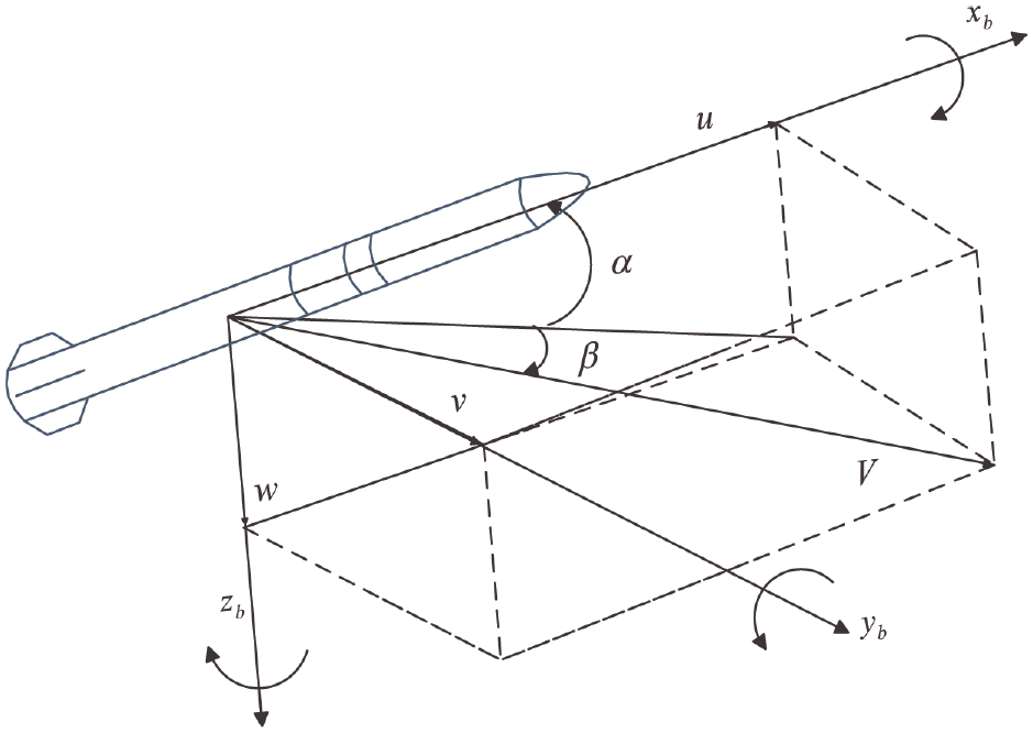
Missile body coordinate frame.
Given a rigid missile flying in three-dimensional inertial space, we can express its equations of motion in terms of translational and rotational motions within the body coordinate frame 28 :
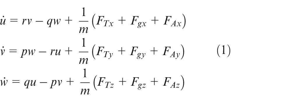
and
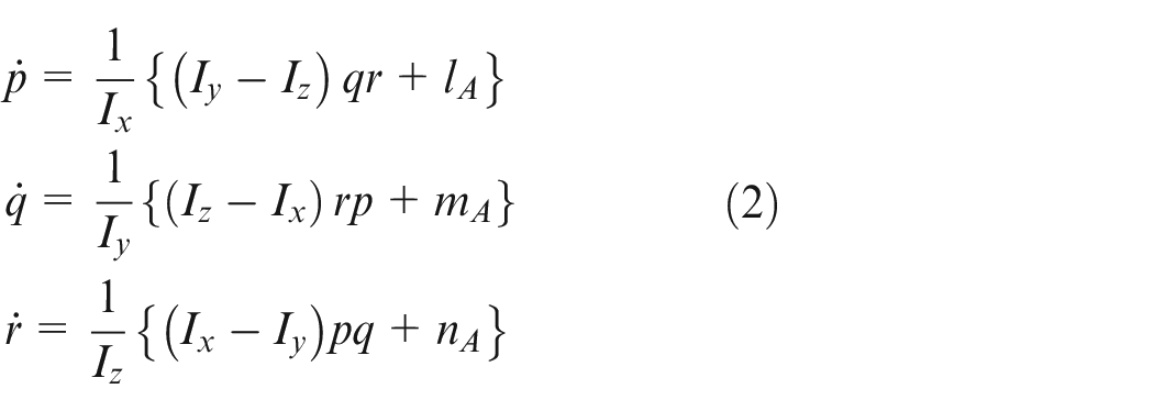
Where the scalar quantity m represents mass and Ix, Iy and Iz are moments of inertia of the missile about x, y, and z-axis, respectively. The missile has an axisymmetric, cruciform shape so that the moments of inertia Iy and Iz are identical. Also, u, v, and w are components of the velocity vector, and p, q, and r, represent components of the angular velocity vector, respectively. FA, Fg, and FT are vectors for aerodynamic, gravity, and thrust forces acting on the vehicle, respectively. Aerodynamic moments are denoted by lA, mA, and nA respectively.
Components of gravity force in the body frame are derived using the following equations 29 :
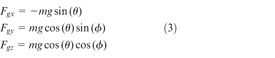
where
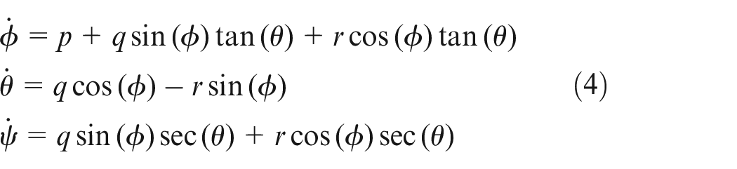
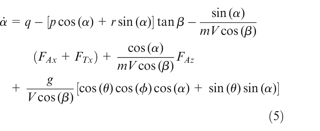
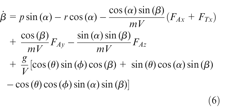
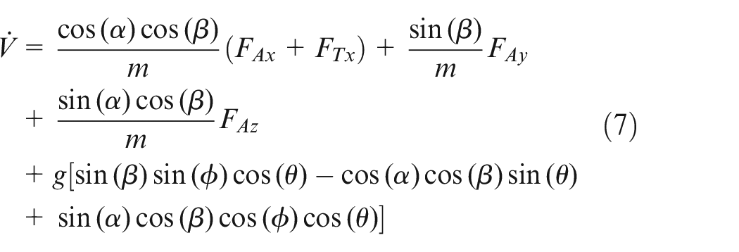
Equation (1) is written as the time derivatives of the body axis components of velocity. However, the variables of interest in flight control are the angle of attack and side-slip angle. According to Figure 1 and some mathematical manipulations, we have:
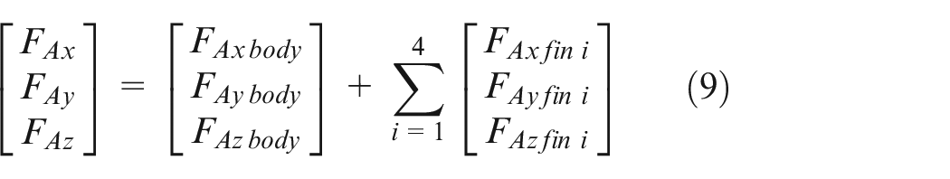
Also, aerodynamic forces and moments about the x, y, and z axes, which depend on the body rates as well as on the equivalent fin deflections, formulated as follows 29 :
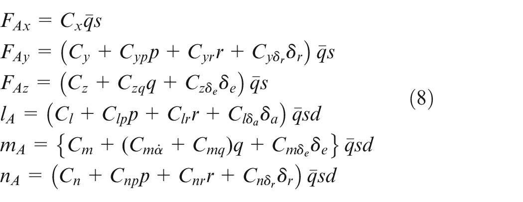
Where
Failure detection and diagnosis scheme
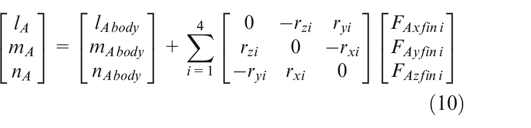
If the aerodynamic control fin becomes damaged or remains closed, it can lead to two types of changes in the aerodynamic model. Firstly, the number of aerodynamic control coefficients is altered, giving rise to new coupling coefficients. For instance, if fin number 1 is damaged, deflection of the elevator may also induce a roll motion. Secondly, the change in configuration and vehicle asymmetry affects both static and dynamic aerodynamic coefficients. In the study conducted by Ashrafifar and Jegarkandi 23 a method for detecting fin failures was proposed. The researchers modeled the aerodynamics of the airframe and lifting surfaces separately, demonstrating their respective effects through simulations. This approach simplifies the identification of model changes. If conventional aerodynamic formulations were used, all coefficients would have to be estimated to detect failures and reconfigure the controller. However, by separating the modeling of the airframe and fins, this issue is mitigated. The following is a brief overview of how the failure diagnosis is conducted.
Mathematical model
where
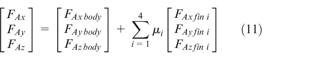
To determine the efficiency of the control fins, a new parameter called µ i is introduced. The µ i have a value between 0 and 1. A value of 1 indicates a healthy fin, while a value of 0 indicates that the fin has not opened or has been completely damaged. This parameter takes into account the effects of the fins in the aerodynamic model. Initially, two DATCOM models were created according to the study conducted by Rosema et al. 30 The first model consisted of only the body and give nose, without any lifting surfaces. In the second model, control fins were added. By comparing the results of these two models, the difference in the aerodynamic coefficients can be attributed to the effects of the control fins. To calculate the fin aerodynamic coefficients, the effects are equally distributed among each fin. This means that the total effect of the control fins is divided evenly among them. Finally, the new parameter µ i is introduced to represent the efficiency of the fins in the overall aerodynamic model.
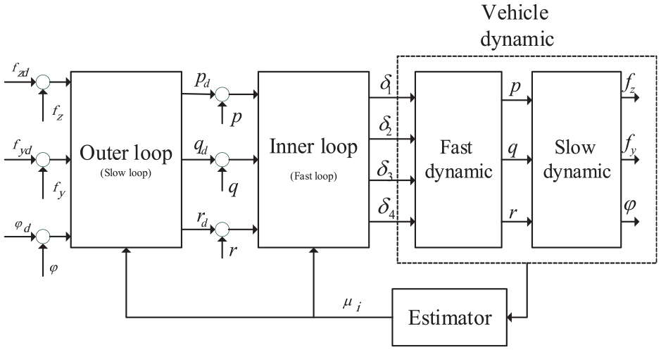
The objective is to determine the efficiency of the control fins (represented by µ i ) over time using a filter estimator. Figure 2 illustrates the proposed strategy for detecting and diagnosing the fin failures.
Failure tolerant control block diagram.
Fin percentage estimation using unscented Kalman filter
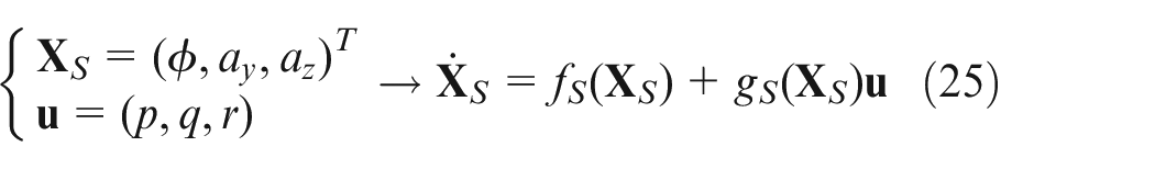
The system dynamics are represented in state-space form as follows:
where
The estimation of parameters through the filtering approach involves an indirect method where the problem is transformed into a state estimation problem. This transformation is achieved by expanding the system state vector to include the unknown parameters (µ i ) as additional state variables. Thus, the constant parameters µ i are considered part of the augmented state vector,

Then, the augmented state vector is defined in (14) as:
The details of the augmented state vector estimation process using the adaptive robust Kalman filter are given in Ashrafifar and Jegarkandi. 23
Fin failure tolerant control design
The previous section introduced a model-based strategy to identify the state of the vehicle following a failure by estimating the health percentage of the control fins. Any changes in the model should be communicated to the controller to facilitate necessary adjustments and prevent mission failure. In this section, two approaches will be presented and their respective results in dealing with fin failures will be compared. The first method involves determining the burning amount on each fin surface and transmitting this information to the servomechanism for compensation. Consequently, it will lead to modifications in the mixing logic related to the affected fin surface area. On the other hand, the second method proposes a two-loop nonlinear controller that takes into account the percentage of fin health. Furthermore, the controller receives feedback regarding the health status of the fins. In the following subsections, these two approaches will be elaborated upon and their distinctive features will be described.
Linear controller design using control allocation
The first strategy involves designing a classical linear control law for the missile using Jacobian linearized models for each decoupled channel. The focus of the controller design in skid-to-turn missiles is twofold: tracking lateral acceleration commands and maintaining a constant roll angle. The missile’s acceleration autopilot and roll autopilot are depicted in Figures 3 and 4, respectively. Designing a classical controller for the single-axis model is equivalent to looking for the gains
Acceleration autopilot for missiles. 29
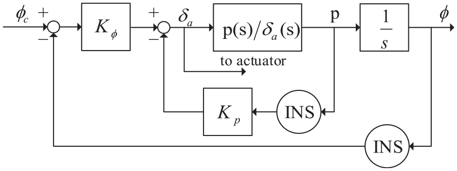
Roll autopilot for missiles. 29
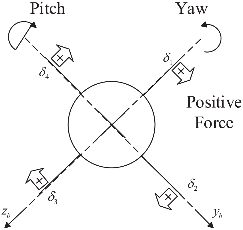
The sign convention corresponding to the fin deflection angles has been shown in Figure 5 and is a positive panel normal force producing a positive roll moment. 31
Fin deflection sign convention.
Therefore, according to sign convention, positive roll, pitch, and yaw moments will be created using the following mixing logic.
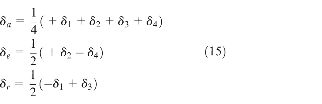
A fourth relationship does not result in a moment, but only in a pure axial force:

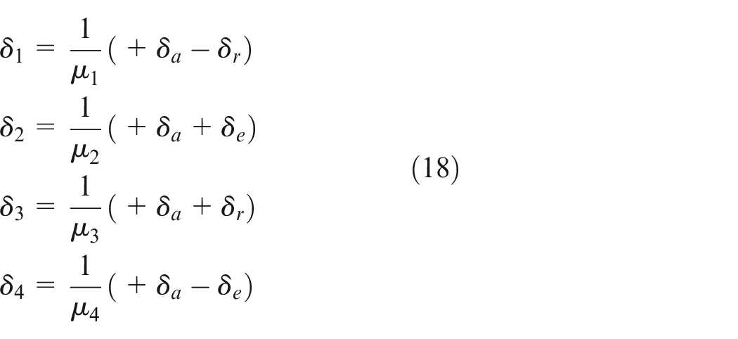
The missile autopilot sends the roll, pitch, and yaw commands to the control allocation block before they can be utilized in the actuator. Therefore, the fin deflection can be obtained as follows:
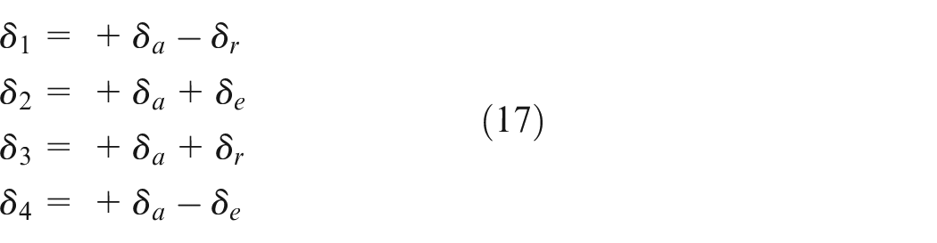
To correct the effect of the fin failure, the above relation can be rewritten as follows:
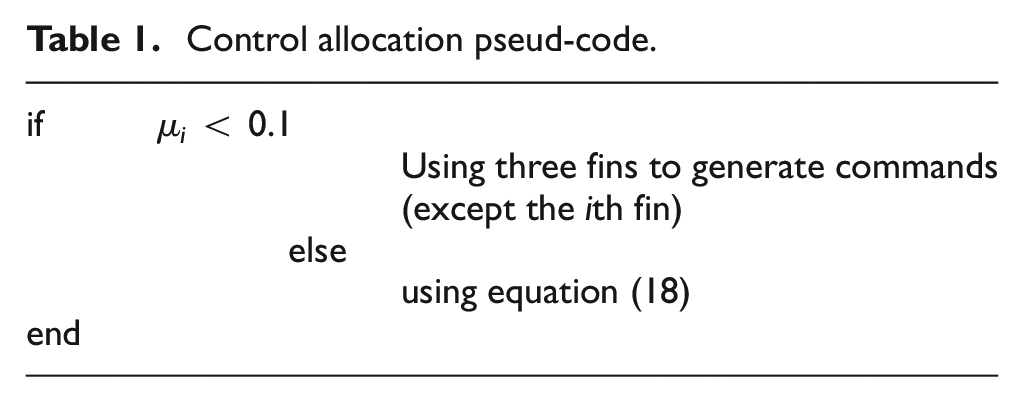
The mixing logic pseudo-code to compensate for the fin failure is shown in Table 1. If more than 90% loss occurs in a fin, the equation (18) will be unusable and the deflection commands can be generated using the remaining three fins.
Control allocation pseud-code.
The
Nonlinear controller design
A two-time scale control structure for the model of the aerospace vehicle has been described in this section (Figure 6). In this strategy, body rates are considered as faster dynamic responses, and roll angle and lateral accelerations are specified as slow dynamics. The commanded acceleration is the reference input to the outer loop controller which aims to produce the required rate command to be used as input in the inner loop controller. The detailed configuration of the inner and outer controllers are presented respectively in the following subsections.
Two-time scale separation controller strategy.
Inner loop feedback linearization controller design
The fundamental concept of feedback linearization is to mathematically transform the dynamics of a nonlinear system into a linear form using state feedback. This transformation has two main forms: input-state linearization, which achieves complete linearization, and input-output linearization, which achieves partial linearization.
32
To access the input-output linearization of the MIMO system we have to differentiate the output of the system until the inputs appear, in the other words, the input appears in the equation of
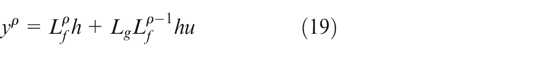
Where
In the inner loop, there are three inputs and three outputs.
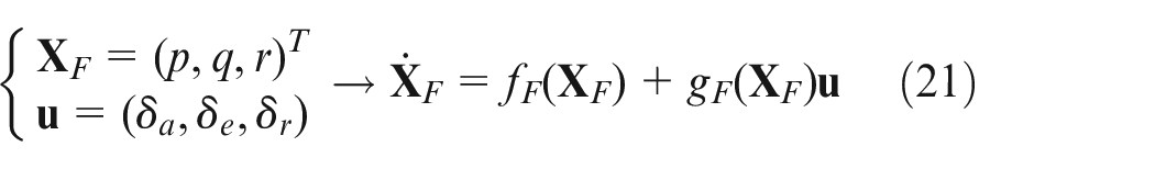
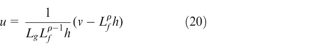
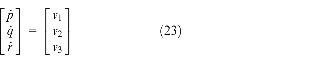
Referring to equations (2) and (3), the relative degree is [1,1,1]. According to equation (19), the control signal to linearize the fast system can be expressed as follows
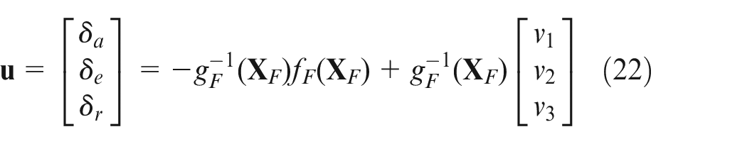
Hence the control law decouples the longitudinal motion and lateral motion.
The feedback law can be designed as
Outer loop feedback linearization controller design
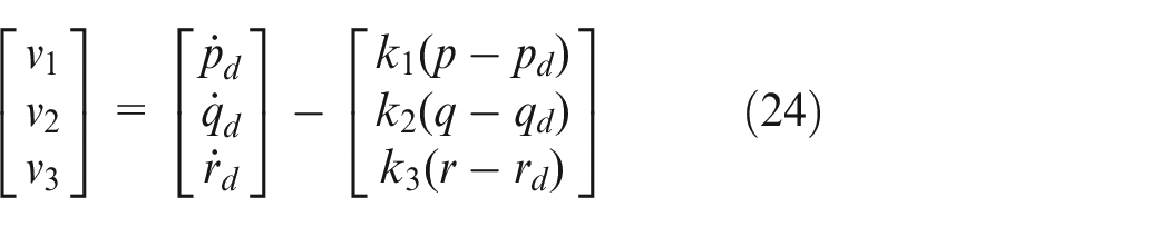
The slow dynamics can also be expressed as follows
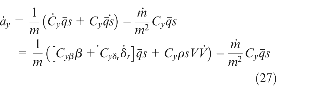
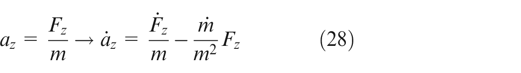
The yaw acceleration dynamics can be described as
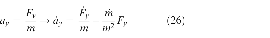
Therefore
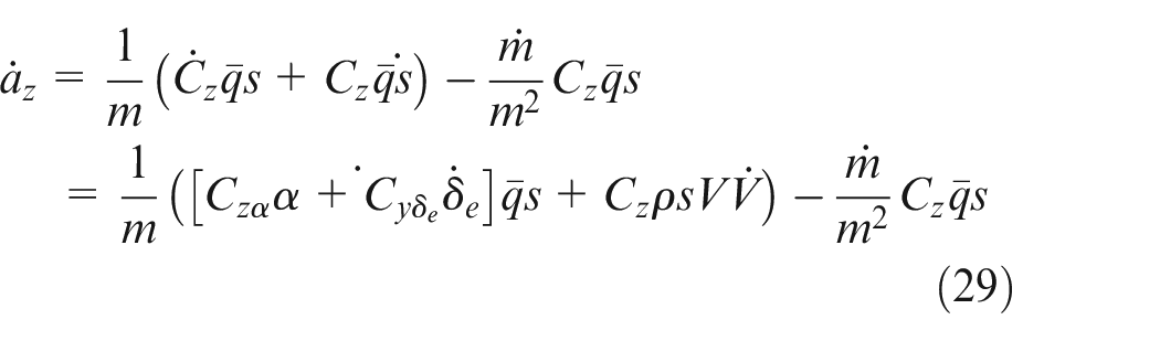
Similarly, pitch acceleration dynamics are also, derived as follows
Therefore
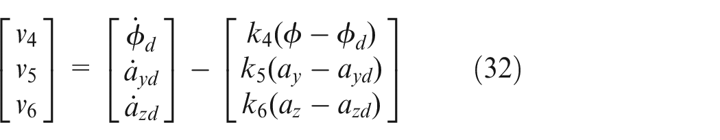
Referring to dynamic equations and (29), (30) equations, the relative degree is [1,1,1] for slow dynamic. Again, according to equation (19), the control signal to linearize the slow system can be expressed as follows
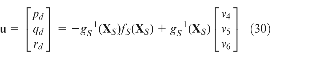
Therefore
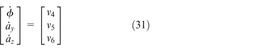
Therefore the above input-output relation obtained is decoupled.
Note that, the equivalent aerodynamic coefficients expressed by equation (8) are used in the controller design, which is a function of
Simulation results
The controllers mentioned earlier are evaluated in the context of an interception mission to assess the effectiveness of the proposed failure-tolerant control strategy. This mission involves an interceptor attempting to strike an accelerated target that follows a predefined trajectory. The initial conditions for both the interceptor and target are provided in Table 2.
Initial conditions.
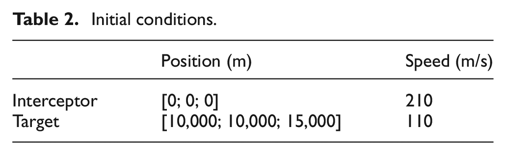
To demonstrate the effectiveness of the proposed controller, three scenarios are investigated. In the first scenario, no failures occur. In the second scenario, it is assumed that 80percent, 30%, and 20% of fins No. 1, 3, and 4 have been broken, respectively; and fin No. 2 began to melt due to aerodynamic heating. Finally, in the last scenario, it is assumed that fin 4 will be destroyed completely 10 s after launch. As mentioned earlier, the proposed aerodynamic model is used for estimation and controller design while the conventional aerodynamic model is incorporated in the simulation.
It is shown in Figures 7 and 8 that in the first scenario, all fins are safe and therefore interceptor hits the target and the estimator estimates
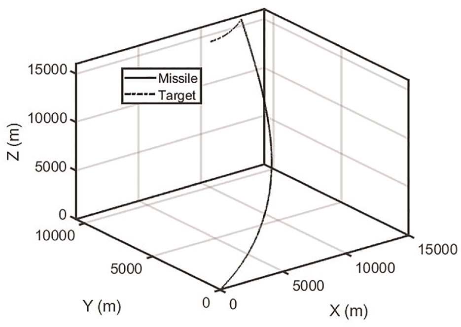
Missile target engagement geometry (scenario 1).
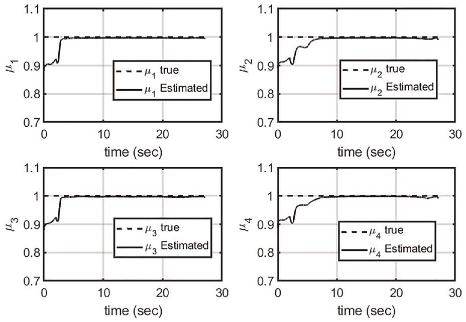
Estimation of the percentage of fins that can generate aerodynamic force (scenario 1).
Missile roll angle (scenario 1).
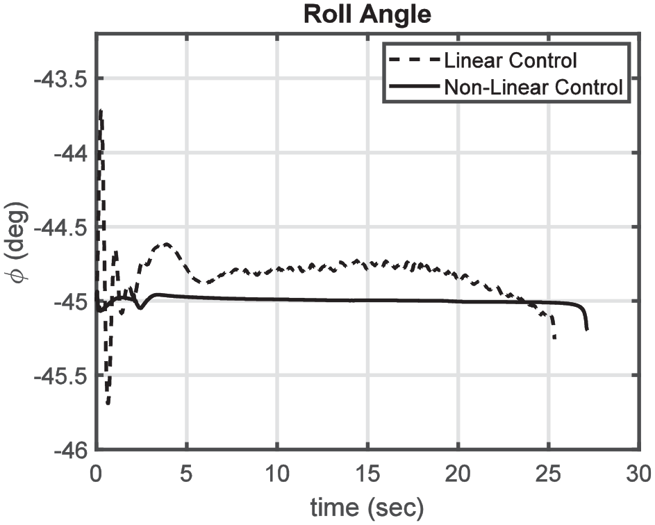
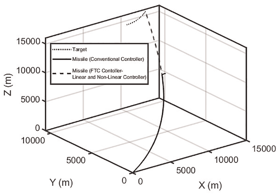
Figure 10 displays the three-dimensional trajectory of the interceptor successfully hitting the target using both the failure-tolerance controller and the mode without it in the second scenario. It is evident that without feedback on the failure of the fin to the controller, the mission will fail. Figure 11 also displays the estimated fin percentage, which provides feedback to the controller. It is clear from Figure 12 that the controllers, given the information of how the fin fails, have been able to prevent the missile from rolling after the fins failure.
Missile target engagement geometry (scenario 2).
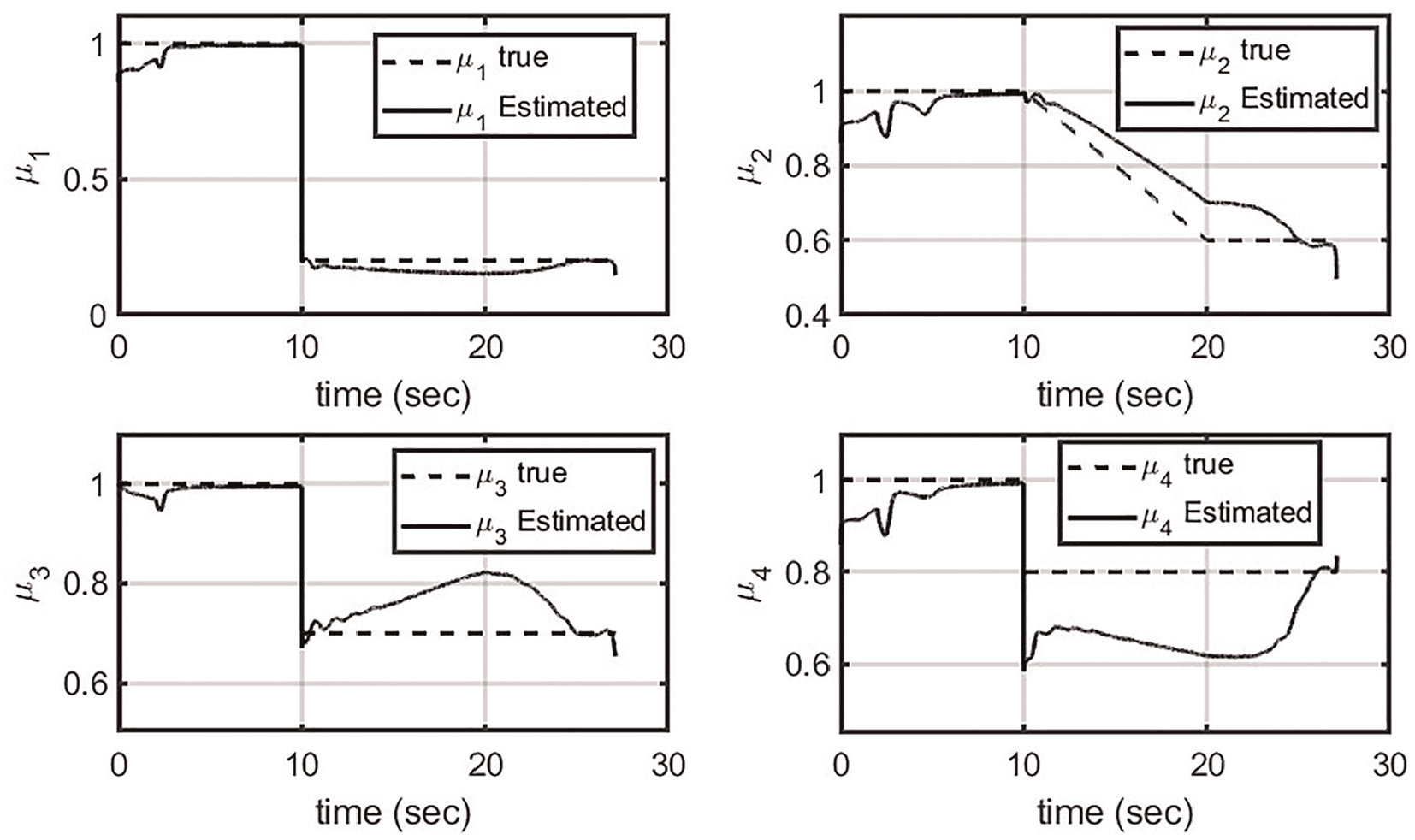
Estimation of the percentage of fins that can generate aerodynamic force (scenario 2).
Missile roll angle (scenario 2).
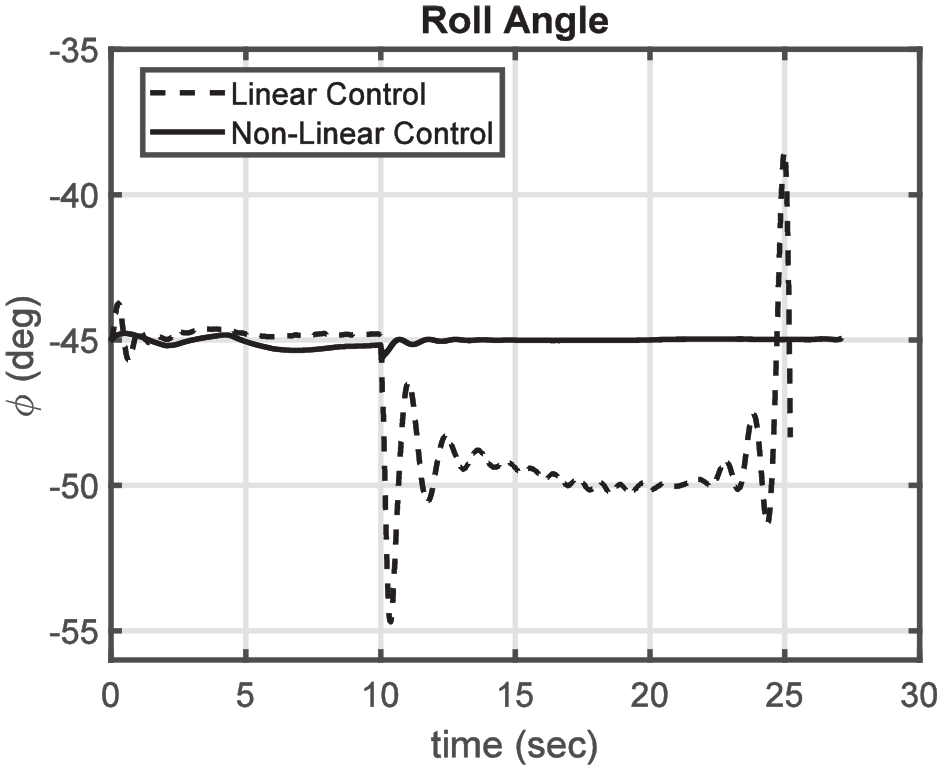
Figure 13 also illustrates that if the information about the broken fin is not utilized in the controller, it will result in mission failure, and the interceptor will not hit the target, in the last scenario. As can be seen in Figure 14, the filter estimates zero value for
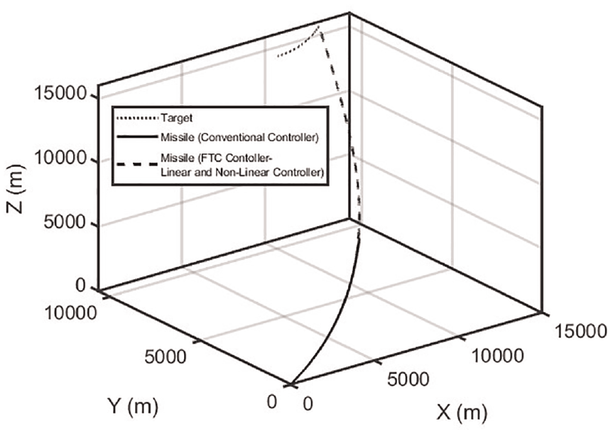
Missile target engagement geometry (scenario 3).
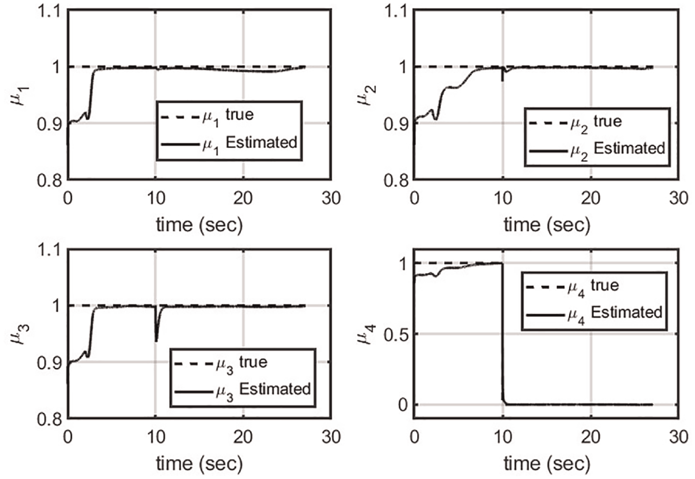
Estimation of percentage of fins that can generate aerodynamic force (scenario 3).
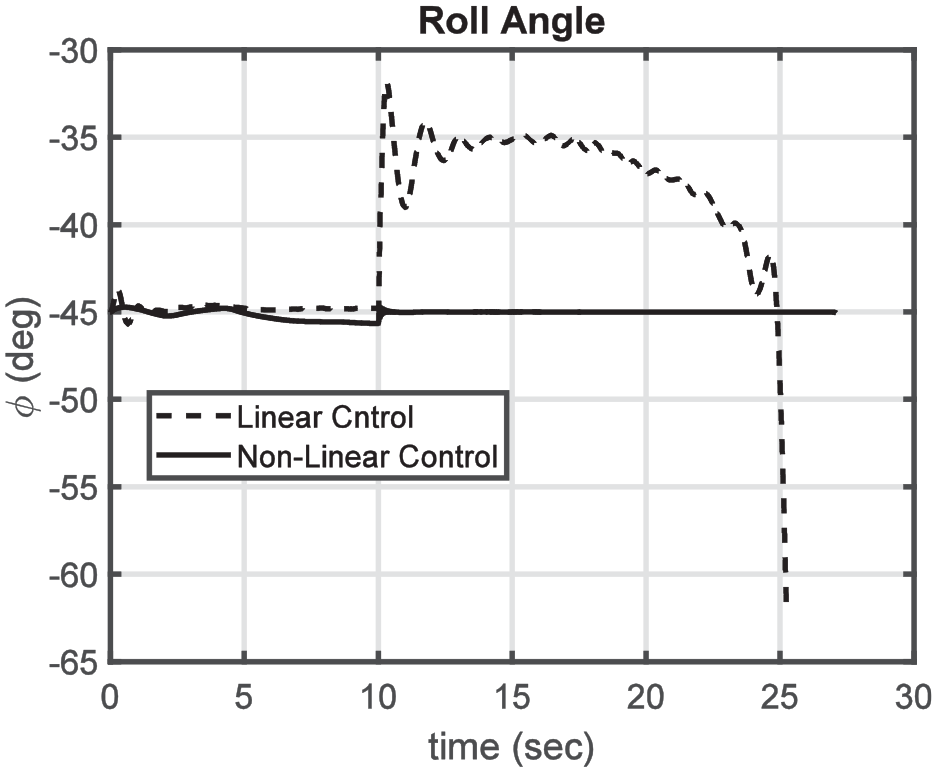
Missile roll angle (scenario 3).
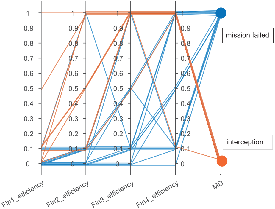
To determine which fins failure scenarios the mission can accomplish or failed, an investigation was conducted on possible scenarios. To achieve this, we have examined various modes of the efficiency percentage of each fin and eliminated duplicate modes based on the symmetry of the missile. The findings are presented in Figure 16. To provide a more comprehensive analysis, we have categorized the target interception results for all fin failure scenarios into two distinct groups. The first group comprises cases where the missile successfully intercepted the target with a miss distance below 100 m, resulting in a collision. The second group includes cases where the missile failed to intercept the target, with a miss distance exceeding 100 m, resulting in mission failure.
Different scenarios of fins efficiency.
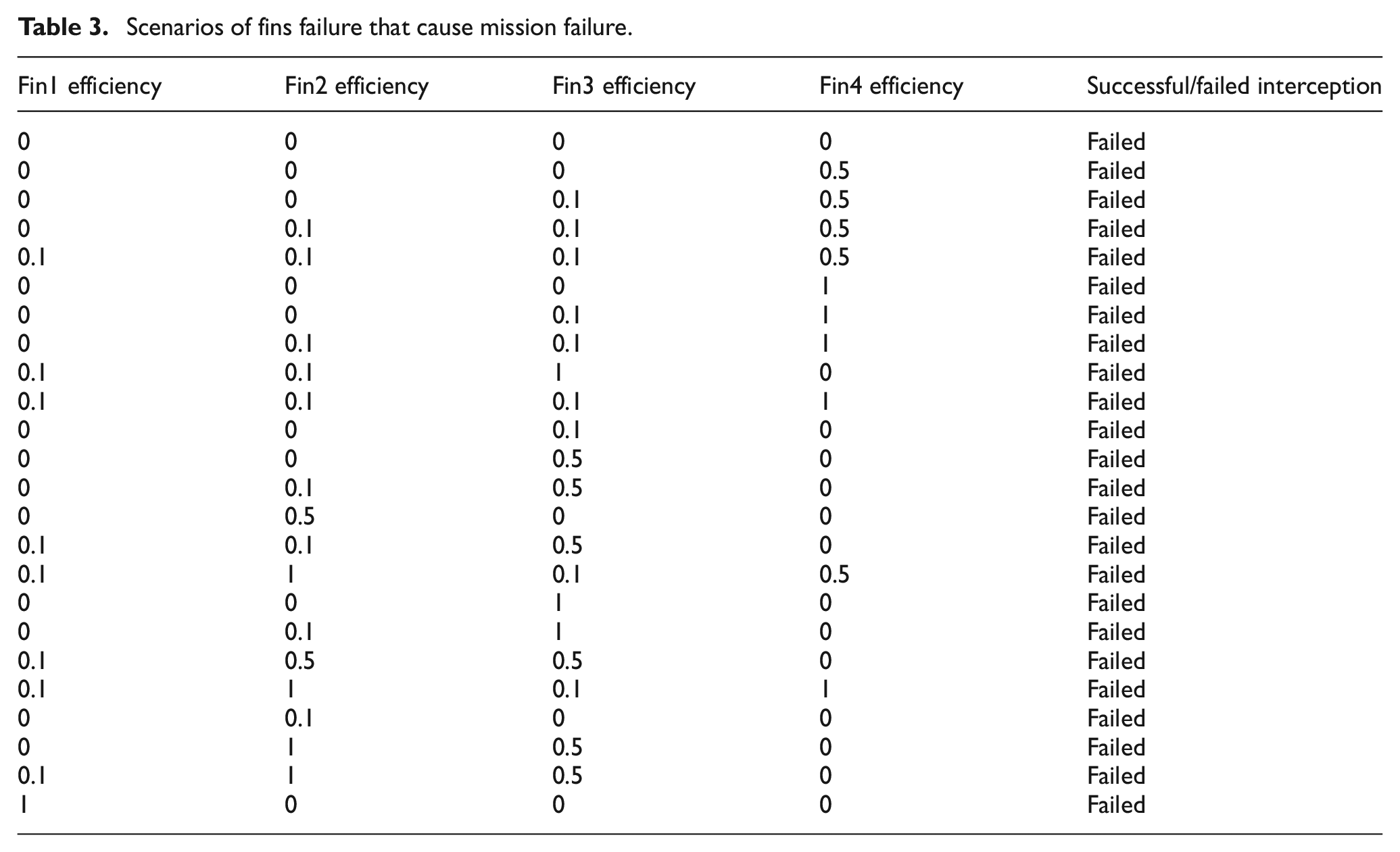
For better understanding, Figure 17 separately displays the scenarios in which the miss distance exceeds 100 m and the mission ultimately fails.
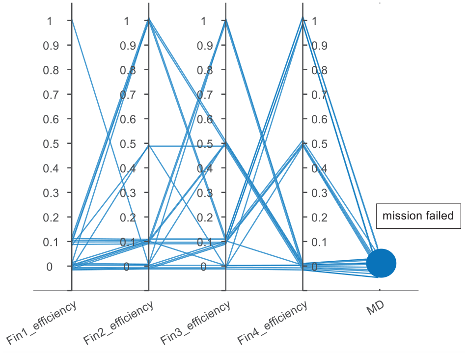
Scenarios of fins failure that cause mission failure.
Also, for better understanding of Figure 17, the related data are shown in Table 3.
Scenarios of fins failure that cause mission failure.
Conclusion
This research paper proposed a fins failure tolerant control approach for a skid-to-turn missile. The key focus is to address the issue of fin failures and develop a control strategy capable of handling such failures. The first step involves proposing an equivalent aerodynamic model to represent the vehicle’s dynamics. Monitoring the health of each fin is achieved by employing a parameter estimated through a nonlinear filter. Two control strategies are then proposed. The first strategy involves designing a classical linear control law for the missile. The mixing law of the fins is adjusted based on the estimated condition of the fins obtained from the parameter estimation. In the second strategy, the dynamic system is divided into fast and slow subsystems using the separation theory. The control signal for the failure dynamics is designed using the principles of backstepping theory. Additionally, the control allocation method is modified based on the condition of the fins to generate the desired control moment. The proposed method demonstrates the capability to quickly detect and isolate fin damage within a few seconds, with high accuracy. Furthermore, the designed controller successfully compensates for these failures, effectively maintaining control of the missile despite fin damage.
Footnotes
Declaration of conflicting interests
The author(s) declared no potential conflicts of interest with respect to the research, authorship, and/or publication of this article.
Funding
The author(s) received no financial support for the research, authorship, and/or publication of this article.
Data availability statement
Data availability statement included at the end of the article.