
Abstract
This paper mainly focuses on dynamic modelling and real-time control for a parallel manipulator with flexible link. The Lagrange principle and assumed modes method (AMM) substructure technique is presented to formulate the dynamic modelling of a two-degrees-of-freedom (DOF) parallel manipulator with flexible links. Then, the singular perturbation technique (SPT) is used to decompose the nonlinear dynamic system into slow time-scale and fast time-scale subsystems. Furthermore, the SPT is employed to transform the differential algebraic equations (DAEs) for kinematic constraints into explicit ordinary differential equations (ODEs), which makes real-time control possible. In addition, a novel composite control scheme is presented; the computed torque control is applied for a slow subsystem and the H∞ technique for the fast subsystem, taking account of the model uncertainty and outside disturbance. The simulation results show the composite control can effectively achieve fast and accurate tracking control.
Introduction
In modern industry there are increasing demands for high speed, high acceleration and high accuracy manipulators. Compared to conventional serial mechanisms, parallel manipulators offer better performance in terms of accuracy, rigidity, and payload capacity, and show more potential to deal with these tasks. Lightweight design of modern mechanical systems can bring a higher operation speed, greater payload-to-arm weight ratio, smaller actuators, and lower energy consumption due to comparatively low inertia. However, lightweight mechanisms will cause structural flexibility under conditions of high speed and high acceleration. Unfortunately, conventional PID control does not take the dynamic effects into account, which causes deterioration in tracking accuracy for the flexible structure. Therefore, flexible dynamic modelling and advanced model-based control of parallel manipulators are essential for high-accuracy tracking [1] [2].
The dynamic modelling of flexible link manipulators has been being investigated for more than 20 years; the modelling of the flexible link can be obtained by the lump mass method (LMM), the assumed modes method (AMM) and the finite element method (FEA), while the system dynamics can be integrated with the help of the Lagrange principle, the Newton-Euler method or the Kane method [3]. For serial manipulators, flexible dynamic modelling has been the subject of intense research [4], whereas few papers have been published on parallel mechanisms because of the closed kinematic chains constraints (CKCCs). CKCCs are usually expressed in the form of nonlinear DAEs, which usually cannot be solved explicitly, making flexible modelling and control very complex [5]. The assumed modes method was applied to derive the flexible dynamic modelling of a 3-DOF parallel manipulator in [6]. Dynamic modelling using FEM is formulated only in [7] with consideration of the flexural deformation; however, the obtained equations are too complex for real-time control. Mills used various methods to formulate a planar parallel manipulator and carried out active vibration control using smart materials [8–10]. To date, the challenge still exists as no previous study has given a definite description of the kinematic chains. Moreover, research on control schemes for flexible parallel manipulators is only in its first phase. Therefore, effective dynamic modelling is necessary for real-time control and control scheme design of a flexible parallel manipulator.
In this study, the AMM-based substructure technique and the Lagrange principle are applied to formulate the dynamic modelling of a 2-DOF flexible-link parallel manipulator towards the end of achieving real-time control; then, an SPT form of flexible dynamic modelling is developed to divide the nonlinear dynamic system into two subsystems for the design of a reduced-order controller. Subsequently, the SPT is proposed to transform the nonlinear DAE constraints into explicit ODEs for the flexible parallel manipulator, in order to reduce computation cost. In order to obtain accurate trajectory tracking performance, novel composite control concepts are developed for the two respective subsystems; the slow subsystem controller is designed using the well-known computed torque control technique for rigid motion control, while the fast subsystem controller is designed using the H∞ scheme for vibration suppression. At the end of this paper, numerical simulations are performed to investigate the effectiveness of the novel control scheme.
Flexible dynamic modelling
Structure description
The structure shown in Figure 1 has two degrees of freedom, and is an example of the PRR (Prismatic - Revolute - Revolute) type parallel mechanism. Two linear direct driving motors, represented as A
i
, can move along the guide rails, which are the actuated joints with coordinates {yi} with respect to fixed coordinate O-XY. This manipulator can realize high-speed positioning and manipulating in the pre-defined region of the X-Y plane. {wi} and {ui} represent the flexural and axial displacement of the flexible link i with respect to floating coordinate Ai -XiYi, respectively;
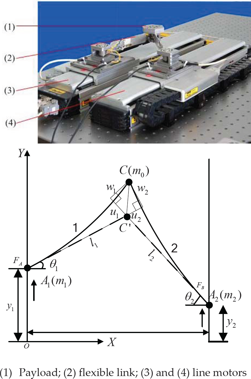
Two-degrees-of-freedom parallel manipulator
For an open chain mechanism, the flexible link dynamic modelling of the serial manipulators can be written as follows [11]:

where
However, for the closed-chain mechanisms, the parallel manipulators have at least one kinematic loop. To derive the dynamic equation for the serial manipulators, the two-DOF flexible parallel mechanism is cut open, as shown in Figure 2, resulting in two separate open mechanisms; this brings two extra dependent degrees of freedom and constraint equations. The equations of motion of the system can be obtained as follows:
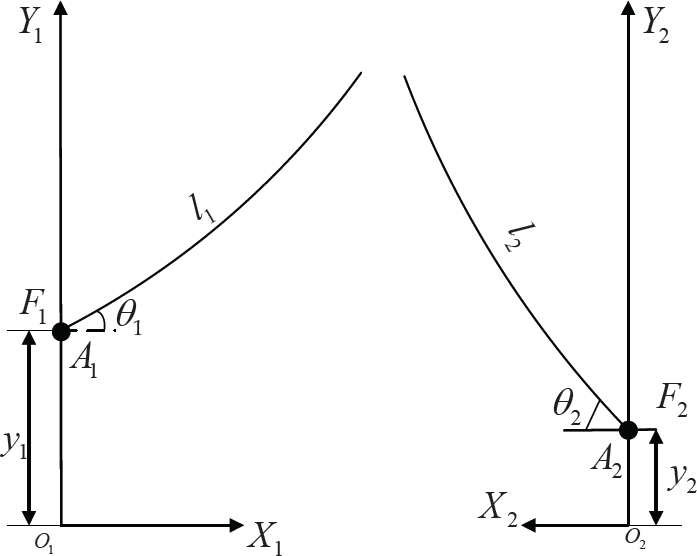
Free system of the parallel manipulator

where ATλ is the constrained force and
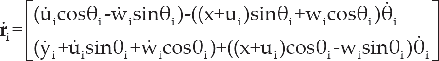
Unlike the real open manipulators, the axial deformation consists of two parts: one comes from the bending deformation and the other from the coupling kinematics of the closed chains; although the former could be ignored in the case of small deformation, the latter must be considered because of coupling kinematics. We assume that the flexible link is an Euler-Bernoulli beam with hybrid bending and axial deformation. Since the manipulator is constrained in the horizontal plane, the influence of gravity on the movement is ignored. The position vector

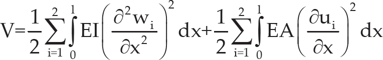
where w i and u i are the bending displacement and the axial displacement, respectively. Then, the kinetic energy of the system can be obtained as:
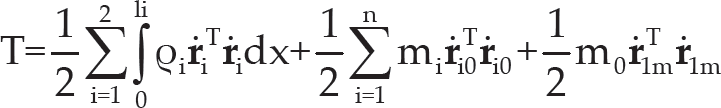
where a dot denotes the derivative in relation to time; ρi, mi, m0 are the linear density of the two flexible link, the lump mass of the two driving ends, and mass of the payload, respectively. Velocity vector
Importantly,
The potential energy of the system can be expressed as:
For real-time control, the AMM-based substructure method was employed to discretize the flexible link. The structural dynamic behaviour is dominated by the first several vibration modes, and the axial natural vibration frequency is much higher than the bending natural frequency; the first vibration mode for axial vibration and first two vibration modes for the bending vibration were chosen.
Based on the AMM and geometry boundary, wi and ui can be derived as in [12].


For simplicity, define
Hence, the equations of motion for the two-DOF flexible manipulators are obtained by using the following general Lagrange approach:

where
Two holonomic constraints can be derived from the geometry of the closed loop chain:

This shows that the constraint equation can be at least differentiated twice with respect to time; according to Implicit Function Theory (IFT), for a given configuration of the parallel manipulator, passive joint parameter θ can be uniquely determined. Hence, if equation (10) is twice differentiated with respect to time, then

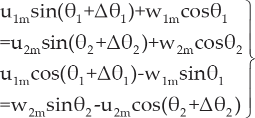
where ϕy and ϕθ represent partial derivatives of y and θ, and ϕyy and ϕθθ represent second partial derivatives of y and θ, respectively. As shown in Figure 1, the axial displacement of the flexible link cannot be ignored because of the deformation coordination principle. The deformation coordination can be derived as below:
where
Because uim, wim and Δθi are all small variables compared to rigid motion, from the Taylor serial equation we can obtain:

Substitute Equations (7), (8) and (13) into Equation (12). The deformation coordination is expressed:

Through Equation (14), the axial modes

where
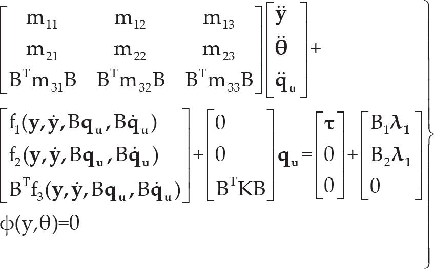
Substitute Equations (5), (6), (7), and (8) into Equation (9). The equations of motion of the system can be obtained thus:

From Equations (15) and (16), the full dynamic model of the flexible parallel manipulator can be expressed thus:
From Equation (17), Lagrange multiplier vector λ

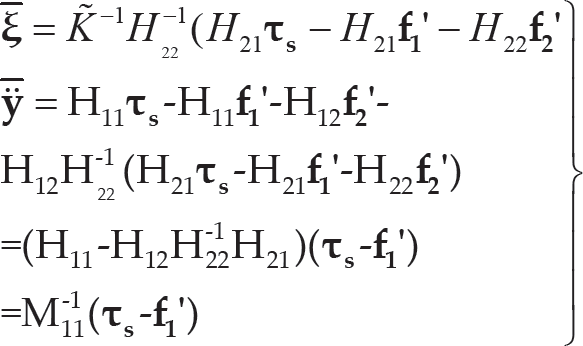
Based on Equation (18), the dynamic modelling of Eq. (17) can be reduced to:

where

Therefore, flexible dynamic modelling of the parallel manipulator can be achieved without the Lagrange multiplier, which would make the design of the controller process easier. The only problem is that, with the unactuated joint variables θ
When the flexure modes of each link introduce independent variables and the degrees of freedom of flexible manipulators are more than the driving forces, the obvious difficulty is that the inverse dynamic and control of the flexible manipulators is quite complex. To solve this problem effectively, the singular perturbation technique has been successfully used in flexible link or flexible joint serial manipulators, dividing the dynamic system into several subsystems in different time scales. Based on previous work [13], this method will be extended to parallel manipulators.
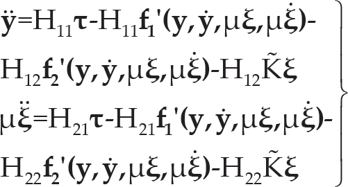
Since the inertial matrix M is positive definite and symmetrical, its inverse matrix H can be partitioned, and the dynamic Equation (19) can be written as follows:

*where K′ = BTKB
To obtain singular perturbation equations, a perturbation parameter should be introduced first. Usually the stiffness parameter K′ is comparatively large. Defining the minimum stiffness kc =min(K′) as the scale factor, the stiffness parameters can be scaled by the scale factor; substituting
To design the control system, Equation (21) should be transformed into the state equation,

Putting Equation (22) into Equation (21), the state equations can be obtained:

Assuming K → ∞, µ is set to zero, the slow subsystem can be obtained:
The fast time-scale can be obtained by
Because the terms of centrifugal force and Coriolis force are the quadratic form of the joint velocity, so

where
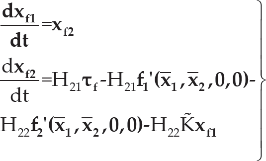
From Equations (10), (24) and (26), the state function of flexible parallel manipulators can be written as:

These are a form of nonlinear algebraic differential equations, which are time-consuming for real-time control if a conventional Newton-Raphson numerical interactive technique is applied. In [14], the author successfully employed SPT in the rigid parallel manipulator, and the result showed high accuracy and robustness to the initial value. Based on previous work, the SPT-based flexible parallel manipulator will be analysed. According to the reasoning of [5], an auxiliary variable w is written as:

w was supposed to asymptotically approach zero and was defined as follows:

where ε1 is a small preselected small positive number.
For any parallel manipulator, the kinematic constraint functions reveal the relationship between geometry and kinematics. Except for the redundant manipulators, the constraint equations are of the index one type, which means that if the general coordinates are given, the unactuating variable can be determined according to the Implicit Function Theory. Differentiate Equation (28) and substitute with Equation (29), and an explicit form ODEs can be obtained:

Thus, the nonlinear DAEs have been transformed into explicit ODEs, which greatly reduce the computational burden and make real-time control for flexible parallel manipulators possible. An analytical explanation of choosing ε1 will not be discussed here.
Figure 3 presents the structure of the composite controller based on two-time scale of the parallel manipulator with the two flexible links given in Equations (24) and (26). Following the composite control strategy, the composite control torque τ can be determined as in [14]:
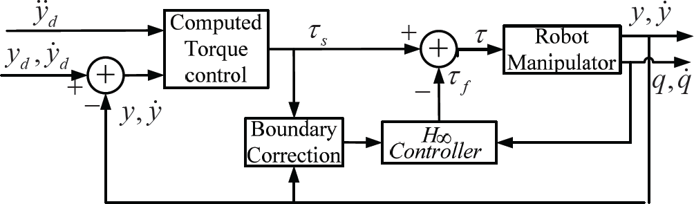
Composite control scheme

where τ
The controller for the slow subsystem can be designed according to computed torque control technique:

where Kp and Kv are diagonal position and velocity gain matrices of the slow subsystem control, respectively, and
Substitute Equation (32) into Equation (24), and we obtain:

where
By selecting appropriate Kp and Kv, the rigid motion of the system can be exponentially stable.
Considering the un-modelled high-order modes of the flexible links and external disturbance, an H∞ -based controller will be designed for the fast subsystem.
The design of the fast subsystem aims to suppress the flexible vibration effectively during trajectory tracking in the presence of un-modelled high-order modes and disturbance. In this paper, a robust controller is proposed for the fast subsystem based on the H∞ strategy. Defining the strain rate Y of the flexible link as:
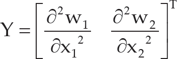
Substituting Equation (7) into Equation (34), we can obtain:

where C is the constant matrix related to the position of the strain gauge and the shape functions.
From Equation (26) and Equation (35), the transfer function of the fast system can be expressed as:

Defining transfer function of the limit torque modes to be G0 (s), then:
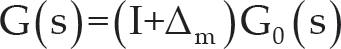
where Δm is the multiplicative perturbation, which satisfies the following equation:
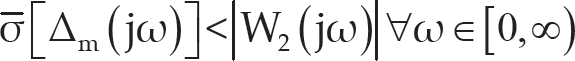
where
The fast subsystem controller is robust to the unmodelled uncertainty and the external disturbances, which means that K(s) satisfies the following equation:

where W1 (s), W2 (s), S(s) and T(s) are the low pass filter, high pass filter, transfer function between disturbance and output, and transfer function between disturbance and control input, respectively.
Equation (39) can be applied to the standard H∞ problem, and the controller K(s) can then be obtained [15].
Simulations will be carried out for the two-flexible-link parallel manipulator to compare the performances of the proposed composite control and the traditional computed torque control (CTC) techniques. Relevant parameters are given in Table 1. The manipulator was commanded to track the smooth desired trajectory, given below:
Parameters of the flexible manipulator

Parameters of the flexible manipulator
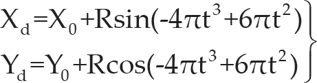
where (Xd, Yd) and (X0, Y0) are the desired tip point position and initial position relative to the fixed coordinate frame, respectively, and R is the radius of the desired circle. The workspace of a two-DOF parallel manipulator can be decomposed into four parts [16], but here we only consider the part when

The trajectories of the proposed composite control scheme and the computed torque control are shown in Figure 4, and the tracking performances of the X direction and Y direction are given in Figure 5 and Figure 6, respectively. The blue curves refer to the desired trajectory, the red curves refer to the CTC control, and the black curves refer to composite control. Figure 7 and Figure 9 show the tracking errors of the two control schemes in X direction and Y direction, respectively. The simulations show that the proposed composite controller can improve the tracking accuracy during the whole motion, and can clearly decrease the maximum error.
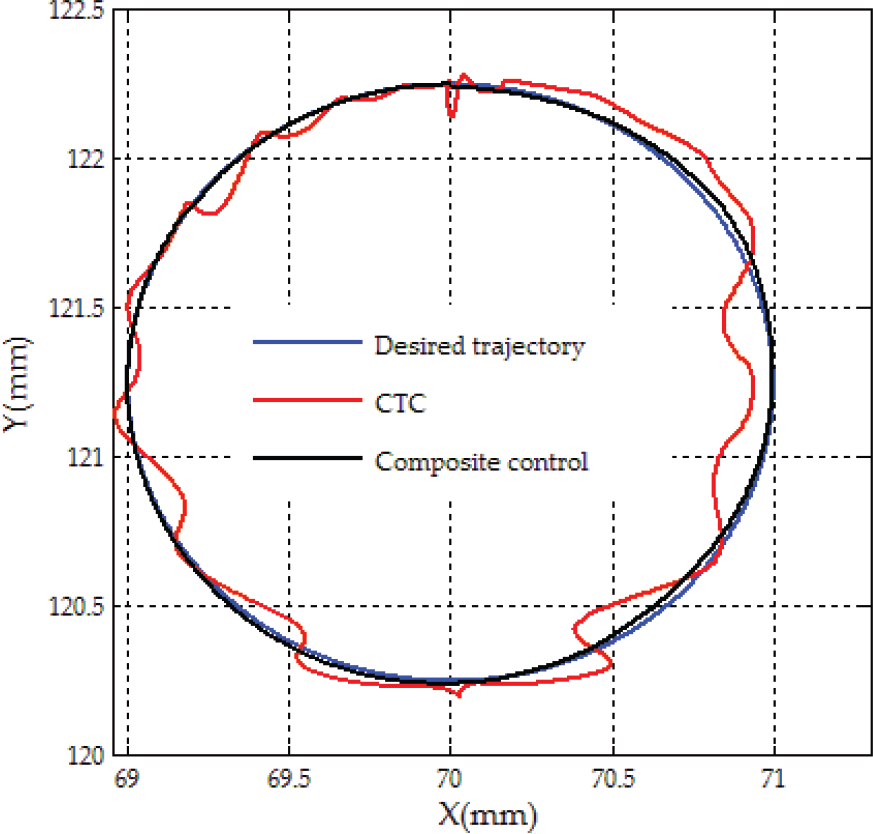
Tracking performance of the desired circle

Tracking performance of X direction

Tracking performance of Y direction

Tracking error of X direction

Tracking error of Y direction
To evaluate the performances of the two controllers, the roots square mean error (RSME) of the end-effector position is introduced as the performance index, and the RSME is defined by:

where xd (i) and yd (i) represent the X direction and Y direction position coordinates at the ith sampling time of the desired trajectory, respectively; x(i) and y(i) represent the X direction and Y direction position coordinates at the ith sampling time of the actual trajectory, respectively.
The RSME of the trajectory tracking simulation using composite controller and CTC are given in Table 2. According to Table 2, the proposed composite control can decrease the RSME significantly compared with the CTC.
RSME of composite controller and the CTC

Generalized dynamic modelling has been established for the two-flexible-link parallel manipulator by using the Lagrange-Euler principle, the assumed mode method-based substructure technique. In contrast to previous research on flexible parallel manipulators modelling, the proposed model found a successful trade-off between model accuracy and computation cost for the purpose of real-time control. Axial deformation was taken into account, which was very important for the parallel manipulator in coupling deformation. The singular perturbation technique was applied to decompose the model into a slow subsystem and a fast subsystem; in doing so, the design of the controller becomes much easier. The proposed singular perturbation technique for the transformation of the DAEs constraint into explicit ODEs for the parallel manipulator greatly reduced the computation cost of kinematics and made real-time control possible. Moreover, a novel composite control scheme for the two subsystems was presented, and simulation showed that the proposed composite control scheme demonstrates better trajectory tracking performance in comparison to traditional computed torque control.
Footnotes
7. Acknowledgement
This work was supported by the National Natural Science Foundation of China (Grant No. 51075086).