
Abstract
Modular construction is a method of construction that involves prefabricating modular indoor spaces in a factory and then assembling them at the construction site. However, dimensional errors made during production in the modular manufacturing factory may hinder assembly at the construction site and delay the entire construction process. In particular, as the quality of intermodular connections determines the structural performance and serviceability of the entire modular building, meticulous quality control is required for the connections. In this study, a method is developed for inspection of the intermodular connection locations to meet the requirements of being accurate, inexpensive, easy-to-use, rapid, and operable by a single person, and then tested in a modular factory. The proposed inspection method consists of three parts: (a) a laser meter mounted on a gimbal, (b) target reflectors based on the tumbling doll principle, and (c) a mobile device as a remote control and for data storage, data post-processing, and visualization of results. The proposed inspection process was tested on a modular unit that had been manufactured at a modular factory; the proposed method outperformed the conventional method in terms of accuracy, inspection time, and work safety. The proposed inspection method allows the accurate and rapid inspection of locations of intermodular connection holes and, thus, its use in modular factories is likely to improve the economics and efficiency of modular construction.
Introduction
Modular construction is a method of construction that involves prefabricating modular indoor spaces in a factory and then assembling them at the construction site. Compared to the conventional cast-in-place construction method, in modular construction, quality control and meeting the construction schedule are relatively easy because many of the processes are carried out in a factory where environmental conditions can be easily controlled.1,2 Modular construction requires less time at the construction site, compared to the conventional method, because the connections between modular units and the foundation and the connections between modular units are made on site. Consequently, the modular method has been used in many construction projects in recent years.3,4 In 2020, Huoshenshan Hospital in Wuhan (China) was quickly built to deal with the rapid growth in the number of COVID-19 patients. Huoshenshan Hospital with 1000 beds is well-known for its modular construction and was completed in just 10 days. In another case, construction of the J57 Mini Sky City, a building with a height of 207.8 m (57 floors), was completed in just 19 days using modular construction, with much less construction dust being generated compared to the conventional construction method. 5
There are primarily two methods for constructing multistory buildings with modular units: stack and infill methods. The stack method involves manufacturing modular units by attaching floors, ceilings, walls, and facilities to a box-shaped main frame in a factory, and then transporting them to a construction site and stacking them into a building. 6 Beams, columns, and walls in modular units serve as the main structural elements, and the method is suitable for multi-family houses or low-rise apartment houses. Since 80% of the construction process is carried out in a factory when the stack method is used, the quality can be controlled more easily and the construction time is reduced by 50%–80% compared to the conventional construction method. 7 In stack modular construction, the foundation and the basement floor are cast-in-place before stacking of the modular units at the construction site. As the quality of the intermodular connections determines the structural performance and serviceability of the entire building, meticulous quality control of intermodular connections is required throughout the entire construction process. By contrast, the infill method involves building the main structural frame at the construction site, manufacturing infill units at the factory, transporting them, and then infilling them into the main frame. 8 In infill modular construction, the main frame, rather than each unit, resists most of the loads, and the quality of the connections between the main frame and the units determines the building’s structural performance. 7 Therefore, the infill method is somewhat better at securing structural performance compared to the stack method and is primarily used in the construction of tall buildings. 9 However, the stack method is currently more popular because the infill method requires skilled workers and, in the event that the process control plan is not established properly, space to store modular units on site.10–12
When the stack method is used, large shear forces, such as from an earthquake or wind loads, are concentrated on the intermodular connections13–16; therefore, quality control of the intermodular connections becomes critical. For this reason, extensive research on intermodular connections and strengthening methods has been conducted recently. Khan and Yan investigated the structural performance and behavior of intermodular connections with bolts and tendons under lateral loads using the non-linear finite element method (FEM).17,18 Chen et al. connected modular units using a plug-in device and a set of tension bolts, then conducted tests under static and quasi-static loads and verified the results using FEM.19,20 Deng et al. tested connection joints reinforced with an external steel plate and a diagonal stiffener under cyclic loading. 21 Ma et al. numerically and experimentally investigated the structural performance of connections reinforced with a plug-in device and a side plate. 22 Most of the previous research on intermodular connections has focused on fastening the top and bottom units using bolts, bars, or shear keys.23–27 However, in order to take full advantage of the designed structural capacity of intermodular connections by accurately combining the top and bottom units, first the connection holes need to be placed in the correct locations when the units are manufactured in the factory. When the connection holes are positioned inappropriately, a typical solution is to increase the diameter of the connection hole during the on-site assembly process.28,29 This additional process prolongs the construction time. Moreover, the enlarged hole reduces the effective cross-section, and eccentricity induces a P-Delta effect, profoundly deteriorating the structural performance of the building; this problem is amplified as the height of the building increases. Therefore, an inspection procedure to check the locations of connections quickly and precisely after the modular units have been manufactured in a factory is crucial to ensuring the design structural capacity and reducing construction time in modular construction.
Inspection of modular units is carried out during or after their manufacture at the factory, typically involving two or more inspectors measuring external dimensions using tape measures (Figure 1) or visually inspecting defects. This conventional inspection method has extremely low accuracy and efficiency, and several studies have shown that it is ineffective for obtaining precise measurements and correcting dimensional errors.30–33 Accordingly, a wide range of studies have been conducted aiming to increase the efficiency and improve the accuracy of inspection of modular units. Recently, a number of studies have attempted to precisely measure the dimensions of a module using a laser scanner.34–38 However, when using such instruments, equipment prices increase quickly in proportion to the performance, and significant time and effort are required for the post-processing of the measured data after scanning. 39 In recent years, various technologies that emerged in the fourth industrial revolution, such as automated inspection based on deep learning and image processing technology40–43 or quality control using blockchain models on site,44,45 have been used in modular construction. However, the application of such cutting-edge techniques to modular construction requires commercialization of the technologies along with trained specialists, which may instead result in cost increases.
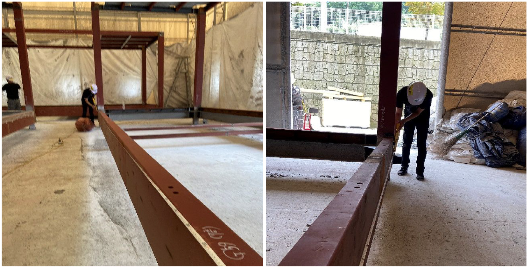
Inspection of the external dimensions of a modular frame using a tape measure.
A new inspection method that allows a single inspector to quickly measure the locations of connection holes accurately but inexpensively in modular factories needs to be developed. Typical intermodular connections are very small in size compared to modular units, and their size and position tolerance are very low, which makes precision essential. However, for most current inspection methods, the required time and cost increase with precision. Long inspection times and excessively high costs lead to delayed shipments and increased production costs, reducing the likelihood of factories using the technology, despite the high accuracy. Therefore, the time required for the process of inspection and analysis of the results should be short, and the equipment cost should not be excessive. The equipment should be easy to operate so that workers can use it without a specialist, and if possible, operable by one person. Therefore, a method for inspecting intermodular connection locations that meets the requirements of being accurate, inexpensive, easy-to-use, rapid, and operable by a single person was developed in this study and then tested in a modular factory.
Inspection method
Background
The stack method can reduce construction time by 50%–80% when compared to the conventional construction method because about 80% of the whole construction process for modular buildings constructed using the stack method is carried out in factories. 7 When using the stack method, large shear forces, such as from earthquakes or wind loads, are concentrated on intermodular connections13–16; therefore, the quality of the intermodular connections determines the structural performance and serviceability of the entire building. Various methods involving plug-in devices, bars, and shear keys have been proposed for intermodular connections; however, bolted connection is still the most commonly used connection method owing to its ease of operation and demountability. 46 Bolted connection for the stack method involves making holes in the top and bottom beam–column joints of a structural frame of each modular unit at the factory and then bolting the modules together at the construction site. The locations of the top holes of the bottom module and the locations of the bottom holes of the top module must align precisely. This study describes the development and application of a process for inspecting the locations of connection holes of modular units as part of the bolt connection method, the most commonly applied connection method in modular construction.
As mentioned earlier, in this study, an inspection process for connection hole locations was developed to meet the requirements of being accurate, inexpensive, easy-to-use, rapid, and operable by a single person. The most critical requirement in inspection is accurate measurement, which can be achieved relatively easily by using a high-accuracy device, such as a laser meter. However, with this method, it is not easy to determine the exact locations of the holes; it can only give precise measurements of the distances between holes. Even when errors are identified after measuring the distances between holes, it can still be challenging to determine how big a locational error is and on which axis, so it takes a long time to figure out how to correct the hole’s location. In this study, an inspection process was designed to not only accurately measure the distances and angles between holes but also constantly make corrections on the x-, y-, and z-axes to ensure that the measuring device is always horizontally and perpendicular to the gravity axis. Moreover, developing an inspection process considering only the accuracy of the device could result in an expensive device that requires specialists to operate it, leading to excessive implementation costs and placing a burden on factories. In this study, a relatively inexpensive inspection process was developed that is affordable and easy-to-use, without the need for specialist operators, as the second and the third requirements, respectively.
The current typical inspection process requires as many measurement setups as the number of connection holes, and measurements need to be taken and recorded manually with no automated analysis of distance errors, which makes the process quite time-consuming. Moreover, as both ends of the tape measure must be held, a pair of workers must carry out the inspection while constantly moving, increasing the manpower requirements. Increasing human resources to reduce the inspection time will further intensify the manpower issue. Increased inspection time leads to delayed shipments and higher manpower requirements lead to increased production costs. A new inspection process that does not address these issues is unlikely to be used in factories. In this study, an inspection process was developed that is faster than the conventional method and requires only one operator, as the fourth and fifth requirements, to enhance its practicality.
Device
As a device that can meet the five requirements (being accurate, inexpensive, easy-to-use, rapid, and single-man operable) with the capacity for measurement of distance as well as horizontal and vertical angles, a laser meter was considered for use in the inspection method. Laser meters that can measure the distance from the device to a target based on the time of flight of the laser pulse are extensively used in various fields today,47–50 and many products have already been commercialized. Determining the relative locations of connection holes requires measuring their distances as well as the angles. Locations of connection holes can be obtained by calculating 3D coordinates using horizontal and vertical angles and distances. Accordingly, a laser meter that is capable of measuring distance, and horizontal and vertical angles was considered.
The modular design guidelines proposed by Lawson et al. define the maximum dimensional tolerance as height/500.
1
Given that the height of a common modular unit is typically 3.0–3.3 m, the maximum dimensional tolerance is supposed to be approximately 6.0–6.6 mm. According to AISC 360-16,
51
the nominal diameter of a bolt hole is obtained by adding 2–3 mm to the bolt diameter. This suggests that the accuracy of the laser meter should be around ±2 mm at most and ±3 mm at least. Along with the accuracy of the laser meter, the measurement range should be considered. A typical modular unit has a length of 6–12 m
52
; however, 15 m long units have been used on rare occasions (e.g. 461 Dean Street Building
53
). When inspecting a modular unit of 5 × 15 × 5 m3 with a measuring device located on the floor 5 m away, a measuring range of
Unlike tape measures, laser meters do not require an additional person to stand at the other end, which makes them single-man operable, because laser meters generally calculate distances by firing a laser at the target and detecting the reflected laser. However, it is recommended to use a reflector to determine whether the precise location is targeted, and the location for laser targeting must be visually identifiable to confirm the location for measurement. The laser meter must be capable of automatically saving inspection records because multiple distances and angles need to be measured quickly. The meter should also allow data export via a wired or wireless connection for later use of the measured data for location analysis and visualization of connection holes. Using a laser meter in a handheld state or measuring by pressing a button on the device may generate errors due to shaking; therefore, the meter must have a mount and preferably be remotely controlled.
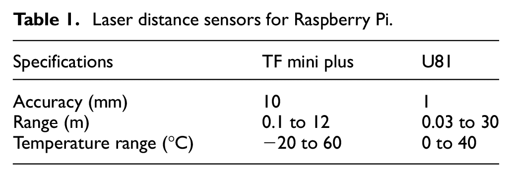
A Raspberry Pi is a single-board computer with the benefits of competitive price, modularity, and being open source, and can be used to make accelerometers, gyroscopes, laser distance meters, sound meters, etc. through connection to various sensors. Such devices have been extensively used in studies on structural health monitoring, autopilot, environment monitoring, etc.54–57 TF mini plus and U81 are laser distance sensors that can be connected to a Raspberry Pi; their specifications are summarized in Table 1. The accuracy and maximum range of the TF mini plus are 10 mm and 12 m, respectively, which do not meet the previously discussed requirements for this study. The accuracy and range of the U81 sensor are 1 mm and 30 m, respectively, which meet the distance accuracy and range requirements of this study, and it has a low price of about $60. However, the U81 sensor does not have an angle-measuring function, so an additional sensor is required to measure them. The results of several distance measurement tests conducted by connecting a U81 sensor to a Raspberry Pi (Figure 2) showed that the initial measured data was unstable although the measured data gradually became stable over time. This suggests that when using this device, a stabilization period is required during the initial setup where measurements are not recorded. It was concluded that the device is not suitable for the inspection application as a large number of measurements can be made quickly.
Laser distance sensors for Raspberry Pi.
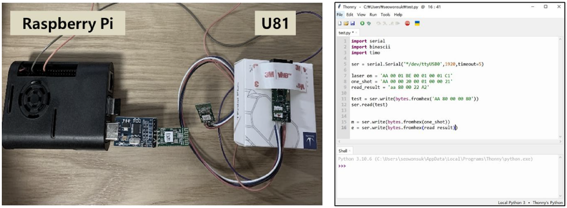
Test using Raspberry Pi with U81 laser distance sensor.
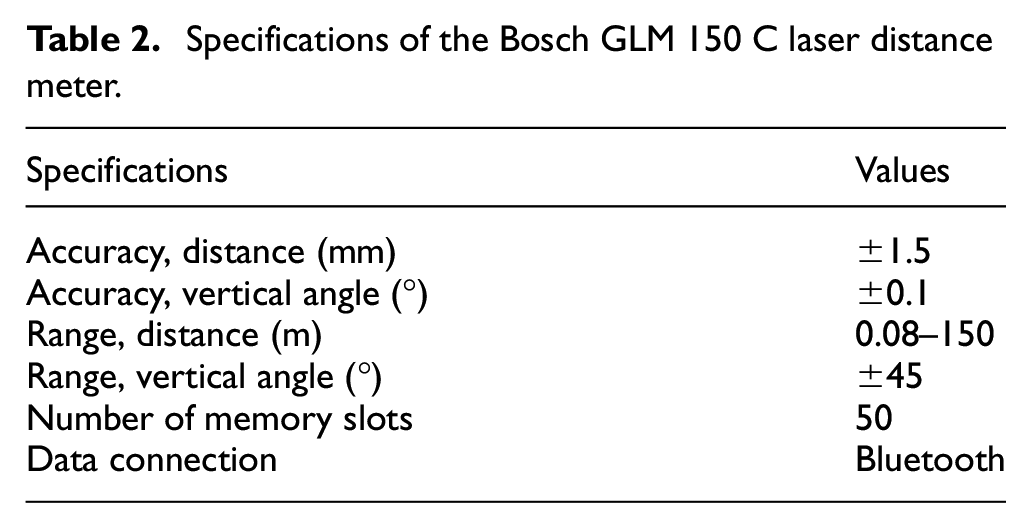
Commercial laser meters were investigated as alternatives, and Bosch’s GLM 150 C product met the requirements. Table 2 shows the specifications of the GLM 150 C. The accuracy and maximum measuring range of the GLM 150 C are ±1.5 mm and 150 m, respectively, and it is priced at around $160. It also has a tilt sensor that is capable of measuring vertical angles with accuracy of ±0.1° and the targeting point can be enlarged and displayed using the built-in camera. It also autosaves measurement results (distance, vertical angle, and camera image) automatically in the on-board memory and can transfer the data to a mobile device via Bluetooth. The device can also be operated remotely using the Bosch Measuring Master mobile application. However, it does not allow measurement of horizontal angles and was unstable when operated in handheld mode, so errors could be made, suggesting the need to use a mount.
Specifications of the Bosch GLM 150 C laser distance meter.
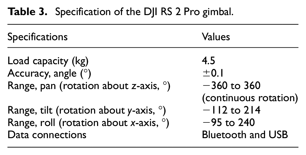
To keep the laser meter stable and to measure horizontal angles, a gimbal was used in this study. Gimbals are typically used as camera mounts and use built-in gyroscopes, accelerometers, and motors to compensate for and stabilize camera shake made by the user’s movement. Recently, gimbals that are capable of pan, tilt, and roll rotation stabilization as well as single-, double-, and triple-axes stabilization have been commercialized. In this study, DJI’s RS 2 Pro Combo gimbal was used, which allows x-, y-, and z-axes stabilization, and measurement of horizontal degrees while continuous rotation. The RS 2 Pro Combo is priced at about $800, and its specification are detailed in Table 3. A laser meter can be mounted on the RS 2 Pro for stabilization, and the rotation of the gimbal can be controlled remotely using the Ronin app.
Specification of the DJI RS 2 Pro gimbal.
The laser meter was mounted on the gimbal to build a distance and angle measuring platform (Figure 3). Once the platform is placed in the desired location, the gimbal adjusts the laser meter perpendicular to the gravity axis in a matter of seconds, regardless of its position or tilt. The gimbal can then be rotated horizontally and vertically using the mobile application, and the user can measure distances and angles remotely by controlling the laser meter; the measurement result is then automatically saved. The use of the gimbal can prevent errors that may be made during handheld and manual operation of the laser meter, as well as enabling measurement of horizontal angles. In conclusion, this method meets all five requirements (accurate, inexpensive, easy-to-use, rapid, and single-man operable) established in this study.
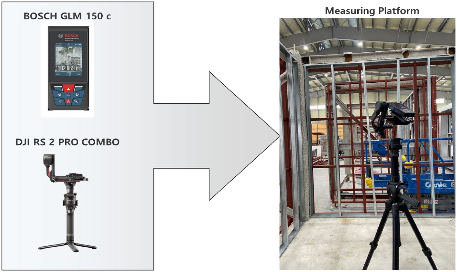
Laser meter mounted on a gimbal.
Targets
Connection holes are located at the top and the bottom of each modular unit and have no vertical protrusion (Figure 1), making it nearly impossible to measure the distance by precisely targeting them with a laser meter. Therefore, pillar-shaped targets were fabricated that can be installed on connection holes for remotely determining the locations of the holes and can be easily targeted using a laser meter. The targets should be large enough to allow targeting regardless of the location of the laser meter and be able to be positioned quickly in the same x and y coordinates as those of the hole. Owing to their pillar shape, if they are tilted after being set up in a connection hole, they can allow errors during the measurement of the distance with a laser meter. Thus, another critical requirement of a target is that it should be capable of staying parallel to the gravity axis. It should also be applicable to both the top and bottom holes of the modular unit.
The top target to use for the connection holes at the top of each modular unit was fabricated by applying the principle of a tumbling doll to a pillar-shaped reflecting bar (Figure 4). Working as a tumbling doll, the target has a wooden reflecting bar at the top, a foam board in the middle, and plastic hemisphere cups and a weight at the bottom; the three parts are vertically aligned. The reflecting bar used for targeting by the laser meter has a diameter of 8 mm to allow identification from a distance; two models of 10 and 15 cm in length were made. To check whether the verticality of the reflecting bar is maintained, a lightweight bubble level was placed on the plate, which was tested in several indoor tests. After the verticality was confirmed, the level was not used in actual tests. The lower part of the top target was made by implementing the tumbling doll mechanism. The center of gravity was located as low as possible using the weight; two hemisphere cups were overlaid, with oil filling the space between them. The outer cup was designed to be placed on the connection hole, and the inner cup and oil were designed to ensure the tumbling doll moves freely so that the reflecting bar can maintain verticality. Low-viscosity oil was used to minimize friction between the inner and outer hemisphere cups and to facilitate balancing. The outer hemisphere cup allows the centers of the hole and top target to be aligned, regardless of the size of the connection hole. The weight of the reflecting bar was 1.2 g/cm (12 and 18 g for 10 and 15 cm lengths, respectively). Based on tests, an optimized weight (54 g) was identified and applied. The production cost per top target was about $15 each. At least four top targets per modular unit are required for inspection.
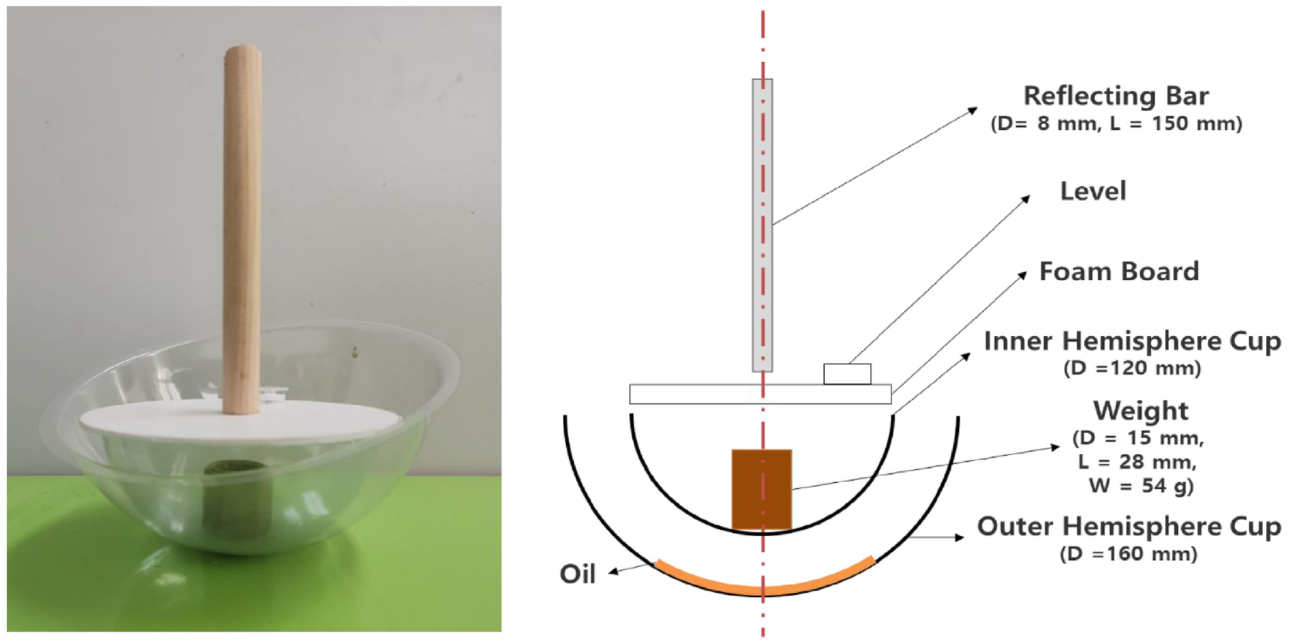
Photo of the target for the connection holes at the top of the modular units and its design.
The bottom target to use for the connection holes at the bottom of each modular unit was fabricated with a line and weight that could be hung on a magnetic hook so that the line was parallel to the gravity axis (Figure 5). After attaching the magnet ball to the bottom hole, the magnet hook was connected to the line, and the weight was tied to the line. The magnetic ball, like the outer hemisphere cup of the top target, allows the centers of the hole and the bottom target to be aligned regardless of the size of the hole. A foam board was inserted between the two magnets to control the attractive force between the magnet ball and the hook and to assist center alignment. The line hanging from the magnetic hook acted as a reflector; a smooth surface and relatively thick line should be used for easy targeting using a laser meter. However, if the line is too thick, it may not hang straight downward. To address the issue, the weight should be increased. Based on several tests, a 4 mm thick 10 cm long line and a 200 g weight were chosen. In fact, the smaller the diameter of the reflector, the smaller the error when targeting with a laser meter. However, when an inspection is conducted by placing a laser meter on the floor away from the modular unit, the top target is located farther from the inspector compared to the bottom target, making a visual check difficult if the reflecting bar has a small diameter. Based on the test results, a decision was made to make the reflector of the bottom target thinner than that of the top target and use a fluorescent green line for easier identification during laser targeting. The production cost of the bottom targets was about $10 each. At least four bottom targets per modular unit are required for inspection.
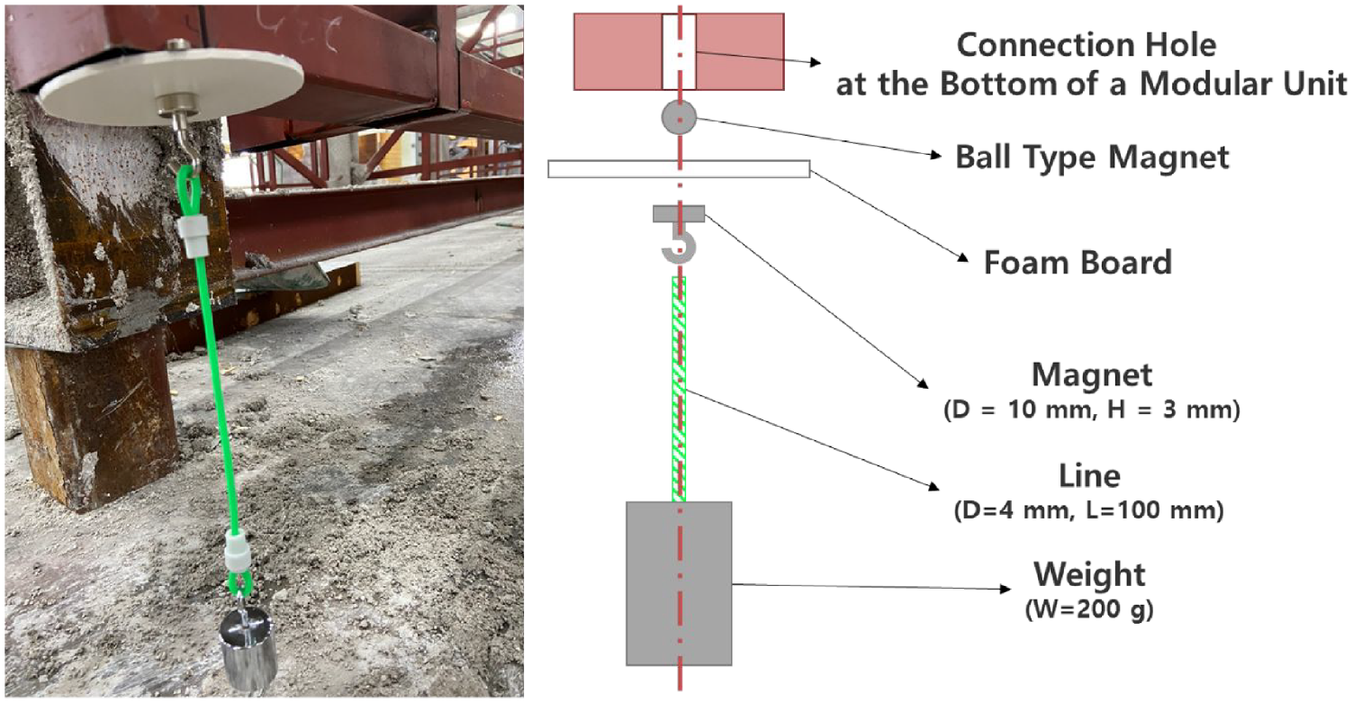
Photo of the target for the connection holes at the bottom of the modular units and its design.
Control
As mentioned earlier, the laser meter and the gimbal can be controlled remotely using a mobile application and can save measured data (distance and angles) to a mobile device. However, determining the locations of the connection holes requires an additional process of calculating the measured data. This requires the development of an application that operates on a mobile device (tablet). This section describes how to control the laser meter and the gimbal and data post-processing, followed by visualization.
For the mobile device, a Samsung Galaxy Tab A2 with an Android operation system was used based on the decision that an 8” tablet will allow users to easily check the measured data and visualize the results on a relatively large screen. The price of the tablet is about $230. The laser meter can be operated remotely using a dedicated Android application, and the measured data is stored on the tablet in JSON file format. The data recorded from the laser meter include measurement numbers, time, distance (mm), and vertical angle (°). The gimbal can also be controlled remotely using a dedicated Android application. After mounting the laser meter on the gimbal, the user can perform balance adjustment using its mobile application to position the device parallel and perpendicular to the gravity axis and control the pan, tilt, and roll motions. In this study, the inspection was conducted by controlling the pan and tilt motions of the gimbal, while keeping the roll fixed. However, while the dedicated application for the gimbal displayed pan and tilt values, it did not have a feature for exporting and saving data, and the manufacturer did not open the source code. Thus, the pan values displayed in the application were extracted using the following steps: (1) run the manufacturer’s application on the tablet, (2) capture the tablet screen every second, (3) recognize the number for a specific location in the captured image and extract it, and (4) save the extracted number in a specific folder on the tablet in a CSV format.
Data visualization
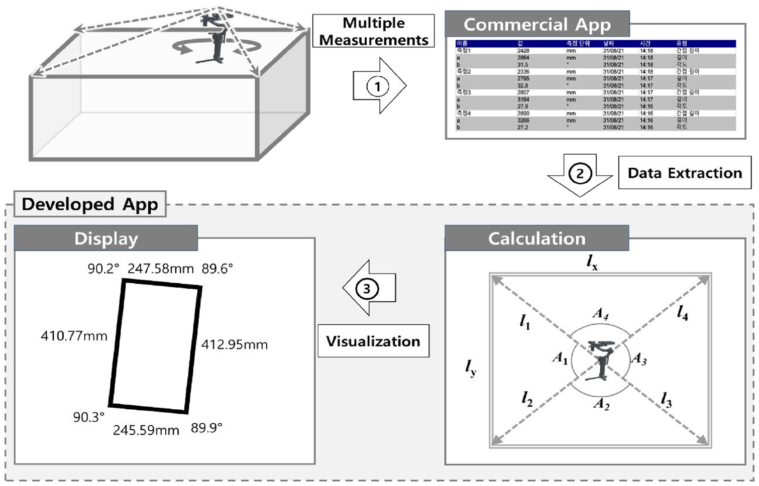
For intuitive data representation, a mobile application was developed to visualize the locations of the connection holes using the distance and vertical angle from the laser meter and the horizontal angle from the gimbal data stored on the tablet. The application was developed using Unity engine, which is one of the most popular tools for 3D video games and virtual reality. Figure 6 shows the schematic flow of the developed mobile application. In the case shown in the figure, the laser meter mounted on the gimbal was placed at the top of the modular unit and the locations of four connection holes at the top were measured while panning. The developed application extracts the data measured by the laser meter and gimbal, calculates sets of extracted data using a trilateration function, and visualizes relative lengths and angles between connection holes on a two-dimensional plane (Figure 7). The application was developed with a graphical user interface (GUI) configured to make it easy for the user to designate items such as the name of a test and a folder, and to check previous data. All of the processes are fully automated, and the proposed inspection process can be carried out easily without a specialist or education.
Schematic flow of the data visualization.
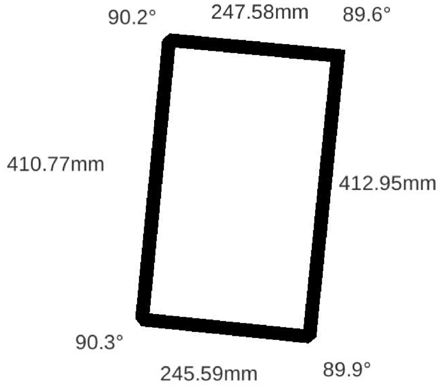
Visualization result using the developed application.
Inspection process
The four-step-process of the proposed inspection method for connection holes at the top of a modular unit is as follows (Figure 8): (1) place the top targets on the connection holes with the help of a lift, (2) set up the laser meter mounted on the gimbal, (3) measure the distance and angle to each target reflector by rotating the gimbal, and (4) check the visualized results using the developed application.
Proposed inspection process for connection holes at the top of a modular unit.
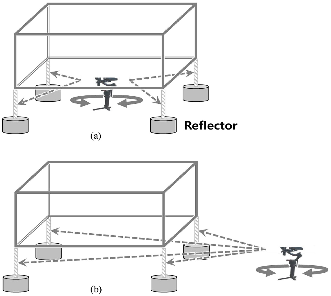
As the laser meter and the gimbal can be controlled remotely, their setup can be varied as shown in Figure 9 depending on the condition of the modular unit and the circumstances at the factory. If the modular unit has a top panel installed, and the inspector can access the top of the unit, the setup in Figure 9(a) in which all the top targets and the laser meter mounted on the gimbal can be set up at once would be the easiest and fastest one. The conventional inspection method with a tape measure can only be used in such a situation. If the modular has no top panel installed, however, inspection should be carried out with the setup shown in Figure 9(b) and (c). In setup (c), the side panel can block the laser, but this problem can be solved simply by using a tripod. It does not require more time even when the tripod is not perpendicular or leveled because the gimbal always maintains the balance. However, as the distance between the measuring platform and the targets increases, the accuracy of the laser meter decreases, so the accuracy decreases in the order of (a), (b), and (c). In setup (a), the inspector must perform the inspection on the top panel, while in setup (c), the inspector can perform the inspection at a distance from the modular unit. Therefore, in contrast to accuracy, the inspector’s safety decreases in the order of (c), (b), and (a). Setup (c) has the benefit that inspection can be conducted even during modular unit fabrication with minimal interference with the fabrication work.
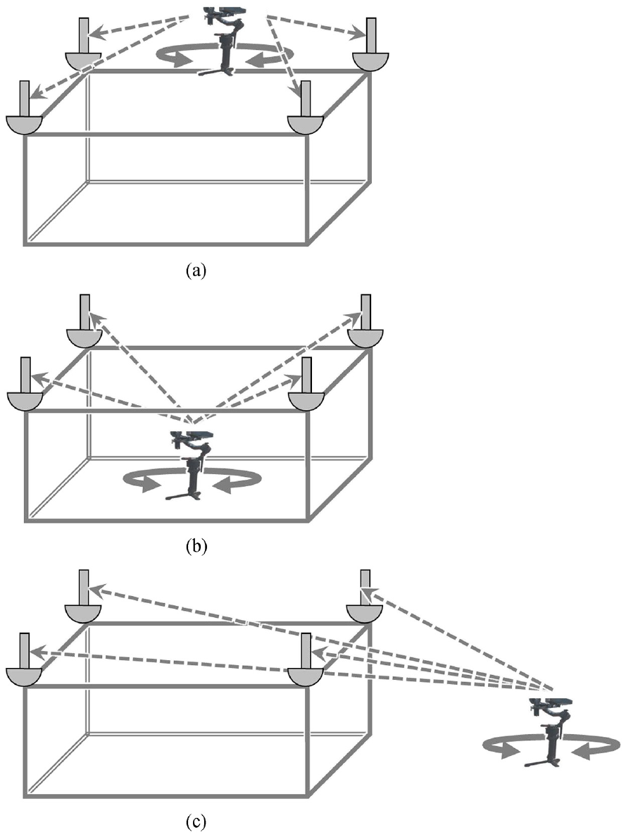
Possible inspection setups for connection holes at the top of a modular unit (a) Laser meter at the top of a modular unit, (b) Laser meter at the bottom of a modular unit, and (c) Laser meter at the outside of a modular unit.
The five-step-process of the proposed inspection method for connection holes at the bottom of a modular unit is as follows: (1) lift the modular unit, (2) attach the bottom targets underneath the connection holes, (3) set up the laser meter mounted on the gimbal, (4) measure the distance and angle to each target reflector by rotating the gimbal, and (5) check the visualized results using the developed application.
The laser meter mounted on the gimbal can be set up in two ways, as shown in Figure 10. If the slab of the modular unit has not been installed yet, as shown in Figure 10(a), the inspector can set up the measuring platform inside the unit. In general, slab concrete casting of a modular unit is carried out at an early stage as it is conducted following the production of the main frame. Thus, in most cases, it is necessary to set up the measuring platform outside the unit for inspection, as in setup (b). As the laser meter stays approximately 40 cm above the ground, to perform the inspection in setup (b), the modular unit must be lifted about 45 cm from the ground. Connection holes are typically located near the edge of a modular unit; therefore, the inspector does not need to get under the module to attach bottom targets to the unit, making the 45 cm working space sufficient to conduct the inspection. As with the connection holes at the top of a modular unit, the accuracy is higher with setup (a), while inspector safety is improved with setup (b). When using the conventional inspection method with a tape measure, the modular unit must be lifted higher than the inspector’s height, and the likelihood of accidents is very high.
Possible inspection setups for connection holes at the bottom of a modular unit (a) Laser meter at the inside of a modular unit and (b) Laser meter at the outside of a modular unit.
Validation tests
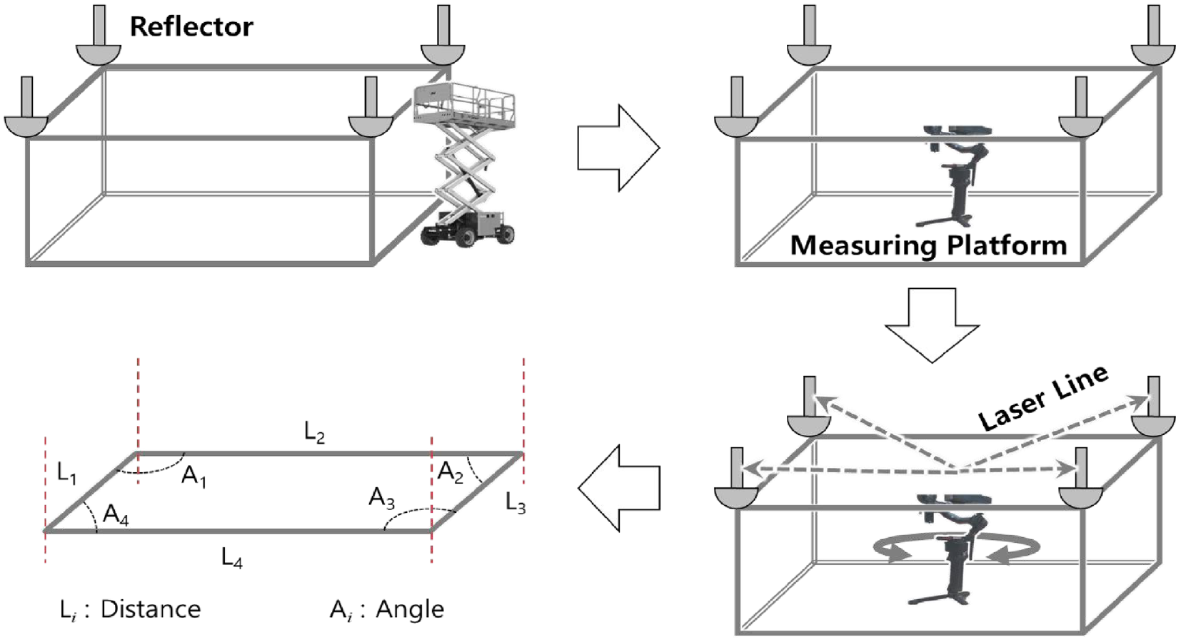
Validation tests were conducted in a controlled environment to determine the feasibility of the proposed inspection process. In the test, four columns were fabricated and located at each corner of a rectangle of 7.2 m length and 2.3 m width. The size of the rectangle was determined based on the actual modular units constructed in a factory. 8 Then, the targets were placed at the top of each column (Figure 11). It is important to note that the dimension of the rectangle was measured by a tape measure placed on the rough ground. Thus, the dimensions of the rectangle used in the test are unlikely to be accurate, and the four corner angles are also unlikely to be perpendicular. While it would have been better to make a rectangle with accurate dimensions for the validation testing of the proposed inspection process, it was not practically possible. Therefore, validation tests were conducted by repeatedly measuring the position of the targets and analyzing the standard deviation of repeated measurements. The measuring platform was placed inside the rectangle (Figure 9(a)) and measured the distances from the targets 10 times, then the measuring platform was placed outside the rectangle (Figure 9(c)) and measured the distances 10 times. The test was carried out by arbitrarily changing the position of the measuring platform by more than 1 m for every measurement. Then, using the developed application, the lengths (l x,1 and l x,2 ), widths (l y,1 and l y,2 ), diagonal distances (d 1-3 and d 2-4 ), and corner angles (A 1 –A 4 ) of the rectangle were calculated (Figure 12).
Setup of the validation test for the proposed process.
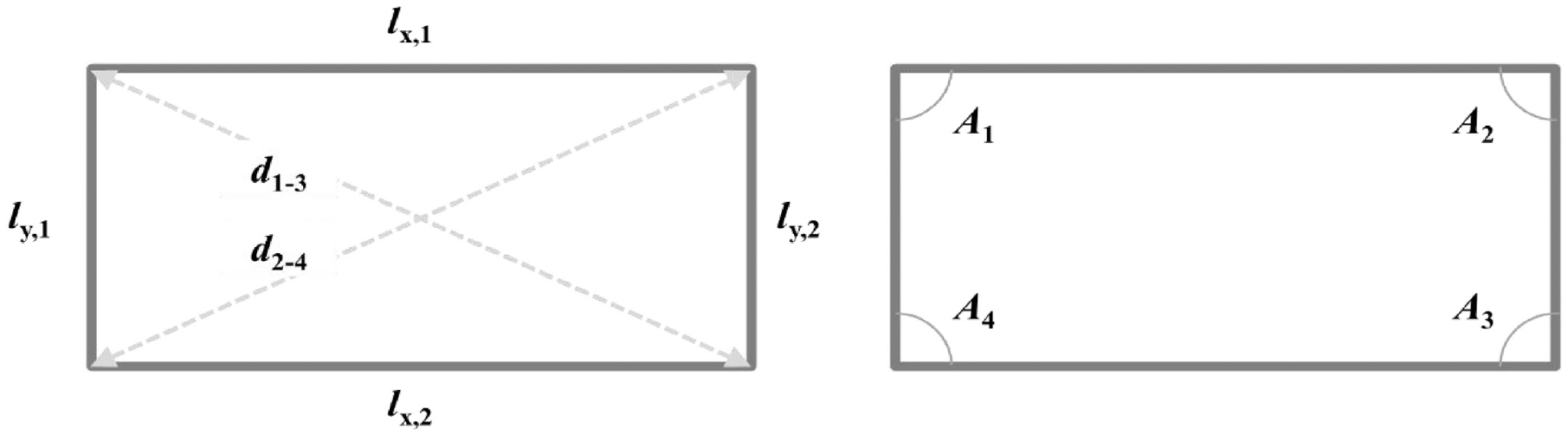
Calculated parameters from the validation test.
Table 4 summarizes the results of the validation tests conducted by placing the measuring platform inside (I1–10) and outside (O1–10) the rectangle, and moving the platform arbitrarily for every measurement. The average lengths of the calculated rectangles, l x,1 and l x,2 , were 7162.5 and 7180.9 mm, respectively; average widths, l y,1 and l y,2 , were 2280.3 and 2294.6 mm, respectively. As expected, the values were slightly different from those obtained using a tape measure. Average diagonal distances, d 1-3 and d 2-4 , were 7534.1 and 7521.3 mm, respectively, and the average corner angles, A 1 –A 4 , were 89.9°, 89.7°, 90.5°, and 90.0°, respectively, deviating from right angles. A comparison between the data obtained by the proposed inspection process and the tape measure shows that the average errors in width, length, and diagonal length were 12.53, 28.27, and 30.75 mm, respectively, showing an increasing trend. The error seems to increase in proportion to the length measured because the distance was measured while the tape measure was not perfectly straight because of the uneven surface.
Validation test results.
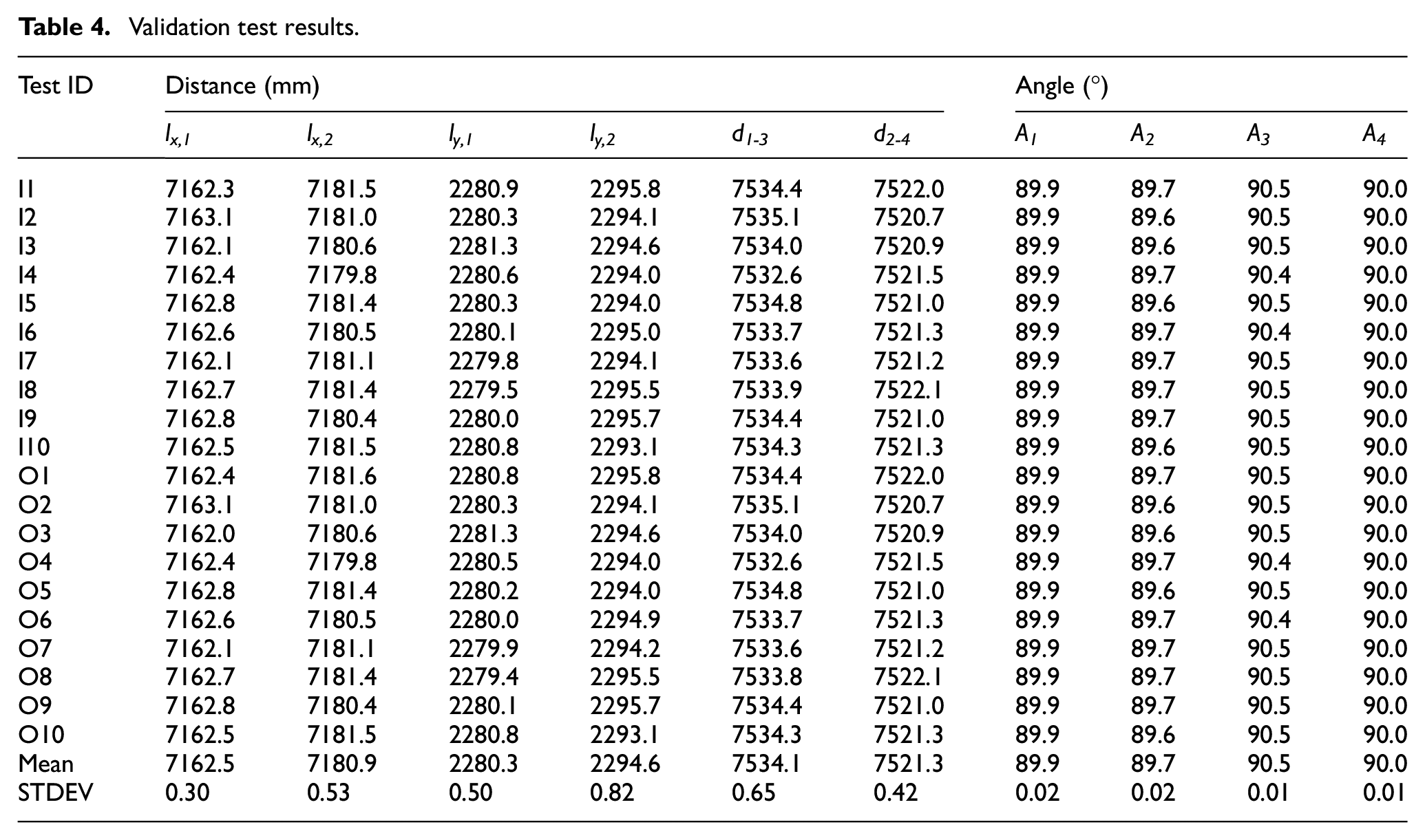
The standard deviations of the data obtained from 20 repetitions of testing conducted by arbitrarily changing the position of the measuring platform during each measurement were: 0.30–0.82 mm for distances (l x,1 , l x,2 , l y,1 , l y,2 , d 1-3 , and d 2-4 ) and 0.01°–0.02° for corner angles (A 1 –A 4 ). Figure 13 shows a box plot of the standard deviations of the test data. The figure and the table show that the deviations in the validation test results are very low. The largest standard deviation was 0.82 mm for l y,2 , which is lower than the previously mentioned accuracy requirement of 2 mm. The standard deviations of other distances were 0.30–0.65 mm, considerably lower than the maximum standard deviation. The standard deviations of corner angles were also very low at 0.01°–0.02°. The results of the analysis of the standard deviations of the measurements obtained from the validation tests conducted by placing the measuring platform inside and outside the rectangle suggest that the accuracy of the proposed inspection process is acceptable.
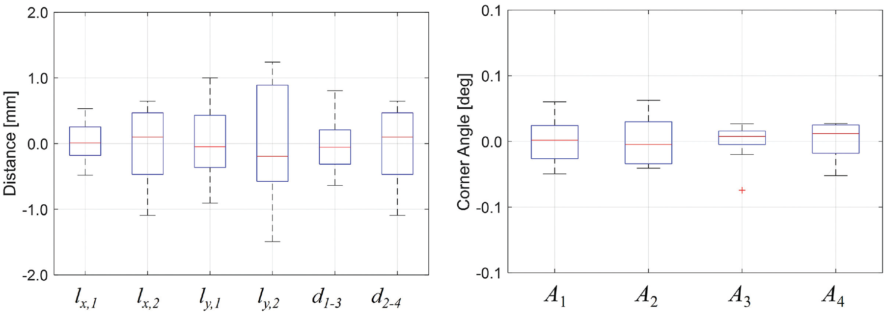
Box plot of the calculated parameters: distances and angles.
Testing at a factory
To validate the applicability of the proposed inspection process, it was tested at a modular manufacturing factory in Korea. The tested modular unit has a single connection hole at both the top and bottom of each column (Figure 14). The locations of the four connection holes at the top were inspected using the proposed inspection process and a tape measure. According to the design guidelines for the modular unit, the distances between connection holes were 8125 mm, 2955 mm, and 8645.67 mm in longitudinal, transverse, and diagonal directions, respectively. Note that diagonal distance measurement is required to determine the squareness of modular units because it allows inspection of the accuracy of length, width, and corner angles. 58 The diameter of the connection holes is 25 mm. The holes were drilled prior to the welding of the top and bottom plate to the box column. If the welding process had not been done accurately, the location of the connection holes would possibly be inaccurate.
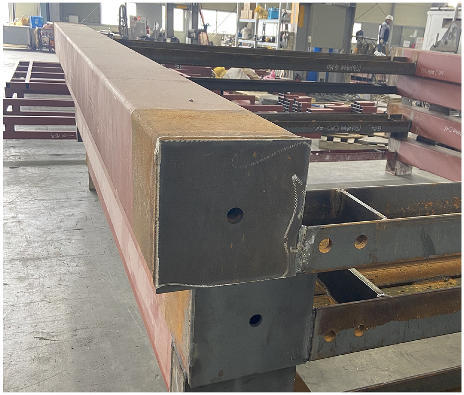
Connection holes drilled at the center of the top and bottom columns.
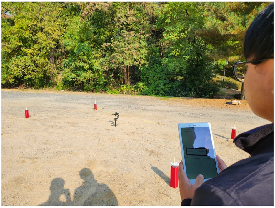
The inspector installed target reflectors on the four connection holes at the top of the modular unit using a scissor lift (Figure 15(a)). Then, the measuring platform was placed inside the modular unit (Figure 15(b)), and, after adjusting the vertical angle of the platform, the inspection was conducted while rotating the platform horizontally. The measuring platform was controlled remotely, and data on distances and angles between the platform and each target reflector were transmitted to and recorded on the tablet, and the inspection results were checked using the developed application. All these processes were performed by a single inspector. The test was repeated five times in total, and the measuring platform was moved arbitrarily by more than 1 m for every measurement. When inspecting with a tape measure, two professional inspectors conducted the inspection. Along with the measured data, the inspection time was also measured to compare the efficiency of the two methods.
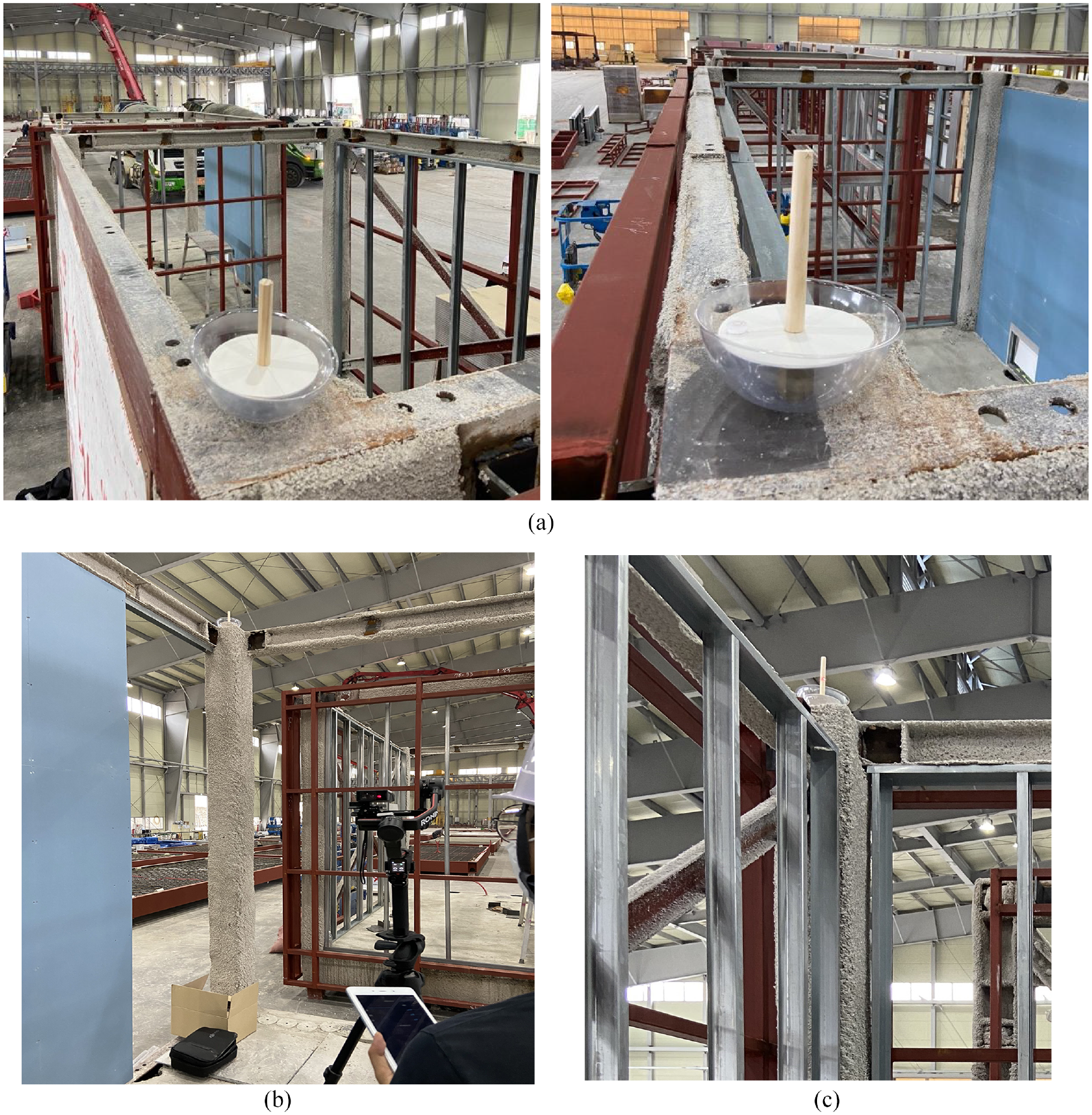
Inspection of a modular unit. (a) Installation of the target reflectors on the connection holes at the top of a modular unit. (b) Setup of the measuring platform inside a modular unit, and its remote control. (c) Visual identification of the red laser targeting spot.
Table 5 shows the results of the inspections. The lengths (l x,1 and l x,2 ), widths (l y,1 and l y,2 ), and diagonal distances (d 1-3 and d 2-4 ) measured by tape measure were 8134.1, 8131.2, 2956.4, 2958.7, 8657.8, and 8658.1 mm, respectively. The mean length, width, and diagonal distance were 8134.2, 2958.1, and 8658.2 mm, respectively. These were 9.2, 3.1, and 12.6 mm shorter in length, width, and diagonal distance, respectively, than the design dimensions of the modular unit (8125 mm, 2955 mm, and 8645.6 mm) mentioned earlier. Note that corner angles were not measured. However, a reconstruction of the rectangle based on measured lengths, widths, and diagonal distances using a tape measure showed that all corner angles were greater than 90°, failing to meet the requirement for a rectangle. This result was likely due to a minute deflection of the tape measure during the inspection conducted using the tape measure. Deflection seems to be greater when measuring diagonal distances (d 1-3 and d 2-4 ). Consequently, all distance data obtained using the tape measure were slightly greater than those obtained using the proposed inspection method.
Inspection results using tape measure (TM) and proposed method (PM).
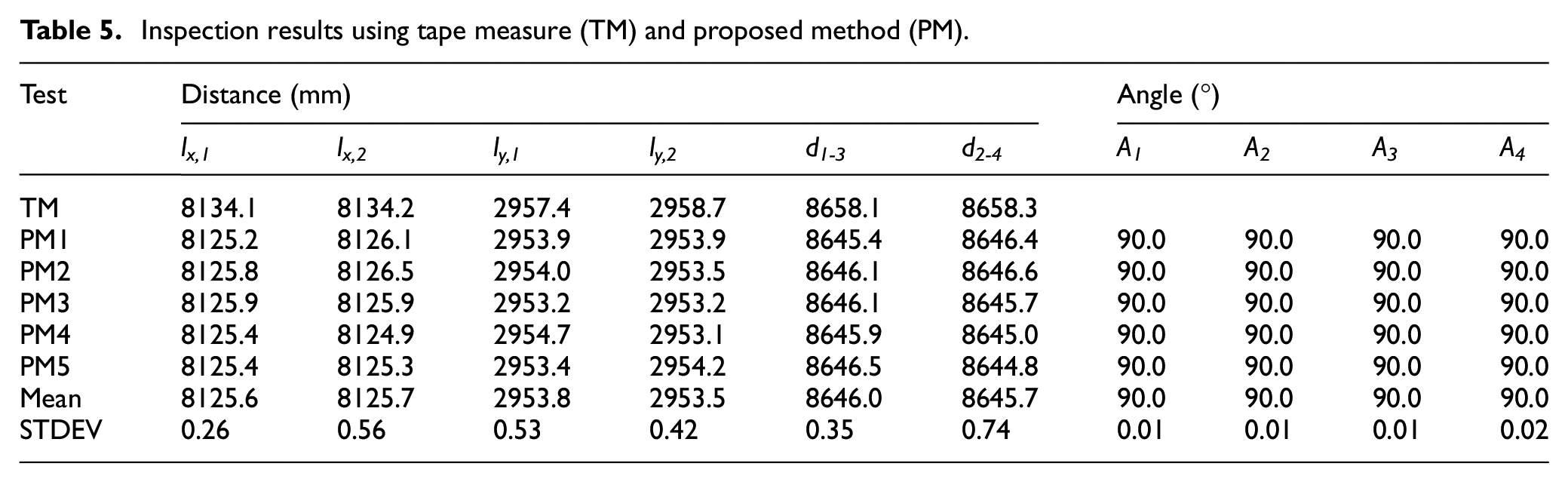
The mean length, width, and diagonal distance of five repeated measurements obtained by arbitrarily moving the measuring platform for every measurement using the proposed inspection process were 8125.6, 2953.7, and 8645.9 mm, respectively. Those measurements were 0.6 1.3, and 0.3 mm shorter than the previously mentioned design dimensions (8125 mm in length, 2955 mm in width, and 8645.6 mm in diagonal distance), respectively. The results of the analysis of the standard deviations of the repeated measurements in this test were similar to the results of the validation tests (0.26–0.74 mm and 0.01°–0.02° in distances and corner angles, respectively).
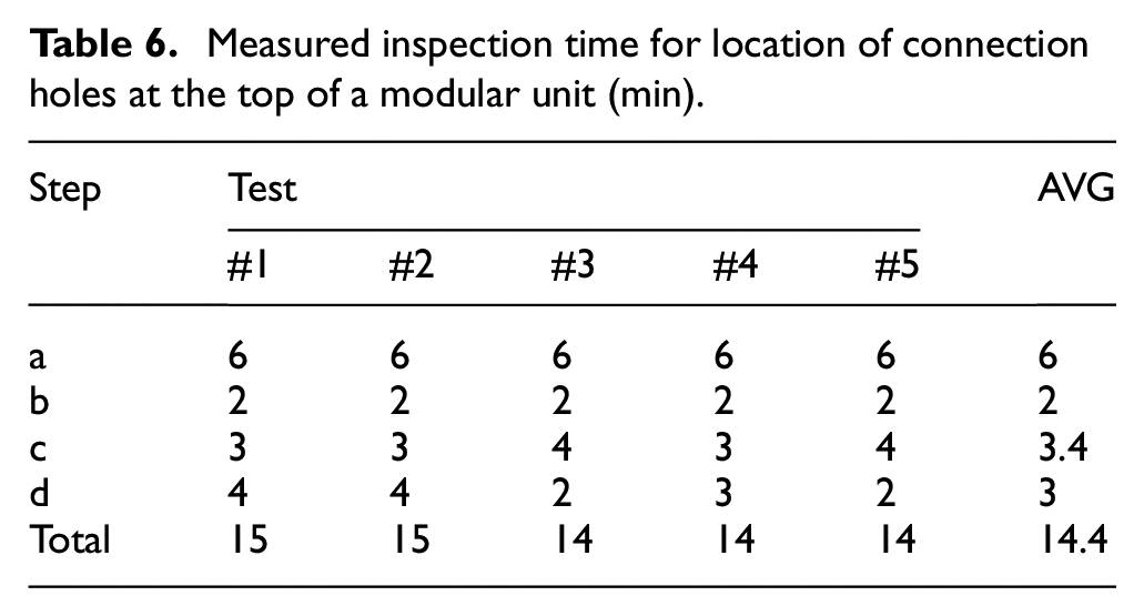
As described earlier, the four-step-process of the proposed inspection method for connection holes at the top of a modular unit is as follows: (a) place the top targets on the connection holes with the help of a lift, (b) set up the measuring platform, (c) measure the distance and angle to each target reflector by rotating the gimbal, and (d) visualize and check the results using the developed application. Table 6 lists the time required for each step. Processes (a) and (b) were performed once during the test and took 6 min and 2 min, respectively. Processes (c) and (d) were carried out five times during the test and took 3.4 min and 3 min, respectively, on average. Accordingly, it took about 14.4 min to measure the locations of four connection holes at the top of a modular unit using the proposed inspection process. If repeated inspections are conducted n times to reduce measurement error without moving the measuring platform, the time required for inspection will be approximately 11 + 3.4n (min). Even when the number of connection holes increases, the increase in the inspection time is expected to be moderate. Note that when using a tape measure, additional computation is required to obtain corner angles. On the other hand, when using the proposed inspection process, lengths, widths, diagonal distances, and corner angles are automatically calculated and visualized instantly immediately after measurement, allowing the inspector to view the results intuitively.
Measured inspection time for location of connection holes at the top of a modular unit (min).
When inspecting the locations of connection holes using a tape measure, two professional inspectors conducted the inspection, and the frequent movement and setup of the tape measure took more time than expected. For each measurement, movement took about 3 min, while straightening and setup of the tape measure and recording the dimensions took about 2 min. In the end, it took 16 min to measure the location of four connection holes at the top of a modular unit using a tape measure. As such, 16 nm min is required when conducting location inspections of m connection holes n times. However, there is no preparation time required, such as the time to set up target reflectors and the measuring platform, unlike the proposed inspection process. On the other hand, as the number of connection holes or the number of inspection repetitions increases, the total inspection time increases rapidly with the conventional method. Moreover, while the proposed inspection process is single-man operable, the tape measure inspection cannot be performed by one person. Further, to inspect connection holes at the top of a module, both inspectors have to be on a lift to carry out the measurements, which requires additional equipment and a larger work environment, and is less safe.
Conclusions
In this study, a method was developed to inspect the locations of intermodular connections that meets the requirements of being accurate, inexpensive, easy-to-use, rapid, and single-man operable. A distance and angle measuring platform was built by mounting a laser meter that can measure distance and vertical angle on a gimbal that can provide triaxial stabilization and measure horizontal degree. The gimbal, regardless of its location or tilt, adjusts the laser meter horizontally and perpendicularly to the gravity axis in a matter of seconds. Then, the gimbal can be rotated horizontally and vertically using its mobile application; distances and angles can be measured remotely by controlling the laser meter, and the measurements are automatically saved. Connection holes are located at the top and the bottom of a modular unit and have no vertical protrusion, making it nearly impossible to accurately target them with a laser meter and measure distances. Thus, a reflection target that can be quickly located in the same x and y coordinates as the connection holes, always parallel to the gravity axis, and can be easily targeted with a laser meter was designed in this study. The top target for connection holes at the top of the modular unit was designed by applying the principle of a tumbling doll to a pillar-shaped reflecting bar. The bottom target for holes at the bottom was made to be parallel to the gravity axis by hanging a line and a weight on a magnetic hook attached to a magnetic ball. In addition, for remote control of the laser meter and the gimbal, storage of measured data, computation of connection holes’ locations, and their visualization, a mobile application that runs on a tablet computer was developed using Unity engine. The total cost of the entire system, including the commercial laser meter ($160), gimbal ($800), tripod ($100), manufactured top ($15 × 4) and bottom targets ($10 × 4), and tablet ($230) was only about $1390.
Prior to testing in a modular manufacturing factory, validation tests were conducted in a controlled environment to determine the feasibility of the proposed inspection process. The position of the measuring platform was arbitrarily changed while measurements were taken 20 times repeatedly. Lengths, widths, diagonal distances, and corner angles were calculated, and standard deviations were analyzed, using the developed application. The standard deviations of the widths, lengths, and diagonal distances were 0.30–0.82 mm, and the standard deviations for the corner angles were very low at 0.01°–0.02°.
Then, to validate the applicability of the proposed inspection process, a test was carried out at a modular manufacturing factory. The locations of the four connection holes at the top of a module were inspected using the proposed inspection process and the tape measure approach. Along with the measured data, the inspection time was also recorded to compare the efficiency of the two methods. When measuring the locations of intermodular connection holes, the proposed inspection method had the following three advantages over the conventional tape measure method. 1) Improved accuracy. When using a tape measure, it is difficult to keep it perfectly straight, and human errors can be made while reading and recording measurements. Measured data were obtained using the proposed inspection process by moving the measuring platform in every measurement while repeating the measurement five times, and the standard deviations of the test results were similar to the results of the validation tests (0.26–0.74 mm and 0.01°–0.02° in distances and corner angles, respectively). 2) Rapid inspection time. The time taken to measure the locations of four connection holes at the top of a modular unit using the proposed inspection process was about 14.4 min, while it took about 16 min when a tape measure was used. The difference is not great, but if repeated inspections are conducted to reduce measurement errors or the number of connection holes increases, the total inspection time required for the tape measure method increases rapidly compared to the proposed process. 3) Enhanced process and safety measures. When using a tape measure, additional computation is required to obtain corner angles. In the proposed inspection process, on the other hand, lengths, widths, diagonal distances, and corner angles are automatically calculated and visualized instantly following measurement, allowing the inspector to check the results intuitively. Moreover, while the proposed inspection process is single-man operable, the tape measure inspection cannot be performed by one person. Further, to inspect connection holes at the top, both inspectors have to carry out the measurements on a lift, which requires additional equipment and a larger work environment, and is less safe.
Currently, the research team is exploring ways to increase the accuracy of the inspection process without making any major changes to the process and with no significant increase in the price of the inspection system. It appears that this could be achieved by using a laser meter with greater accuracy. Moreover, to eliminate potential human errors during targeting, an auto-targeting method are under development. This is likely to be achievable by using a laser meter that is capable of continuous measurements while slowly rotating the gimbal and programing to recognize the moment at which the laser is on the target. To implement this, the requirements regarding the distance, rotation speed, and continuous measurement frequency must be met. However, there are no commercial products currently available to meet the requirements. Meanwhile, in modular construction, connections between the left and right modules, in addition to connections between the top and bottom modules, are very important parameters that determine structural performance. Thus, future research should expand the inspection process to apply to the inspection of lateral intermodular connections.
Footnotes
Declaration of conflicting interests
The author(s) declared no potential conflicts of interest with respect to the research, authorship, and/or publication of this article.
Funding
The author(s) received no financial support for the research, authorship, and/or publication of this article.
Data availability statement
The data that support the findings of this study are available on request from the corresponding author, Jinyoung Kim.