
Abstract
Aiming to address the issue of mapping failure resulting from unsmooth motion during SLAM (Simultaneous Localization and Mapping) performed by a quadruped robot, a tightly coupled SLAM algorithm that integrates LIDAR and IMU sensors is proposed in this paper. Firstly, the IMU information, after undergoing deviation correction, is utilized to remove point cloud distortion and serve as the initial value for point cloud registration. Subsequently, a registration algorithm based on Normal Distribution Transform (NDT) and sliding window is presented to ensure real-time positioning and accuracy. Then, an error function combining IMU and LIDAR is formulated using a factor graph, which iteratively optimizes position, attitude, and IMU deviation. Finally, loop closure detection based on Scan Context is introduced, and loop closure factors are incorporated into the factor graph to achieve effective mapping. An experimental platform is established to conduct accuracy and robustness comparison experiments. Results showed that the proposed algorithm significantly outperforms the LOAM algorithm, the NDT-based SLAM algorithm and the LeGO-LOAM algorithm in terms of positioning accuracy, with a reduction of 65.08%, 22.81%, and 37.14% in root mean square error, respectively. Moreover, the proposed algorithm exhibits superior robustness compared to LOAM, NDT-based SLAM and LeGO-LOAM.
Introduction
Quadruped robots are a type of mobile robot known for their excellent passability, mobility, and promising application prospects. They have found wide application in tasks such as inspection, search and rescue, and mapping.1–4 As the demand for these tasks increases, the autonomous navigation performance of quadruped robots is being subjected to higher and higher requirements. Real-time localization and map construction technology, known as Simultaneous Localization and Mapping (SLAM), is a key technology for determining the autonomous navigation performance of mobile robots. 5 The SLAM framework can be broadly divided into four main components: front-end odometry, back-end optimization, loop closure detection, and map construction.
Zhang and Singh proposed the LOAM (Lidar Odometry and Mapping) method, which tackles the complex problem of localization and map construction by combining two algorithms: rough alignment and fine alignment. 6 These algorithms operate at frequencies of 10 and 1 Hz, respectively, demonstrating good performance. However, the LOAM method lacks loop closure detection, and the accuracy of the odometry is affected by distance errors.
Shan and Englot proposed LeGO-LOAM, an extension of the LOAM method, which incorporates a data preprocessing module, loop closure detection module, and back-end optimization module to form a more complete laser-based SLAM scheme. 7 These methods have achieved favorable results in scenes with smooth motion. However, in practical applications where robots encounter running and jumping scenarios, the above methods are less effective or even fail to perform in such demanding motion scenarios.
To enhance the robustness of SLAM algorithms, many scholars have proposed fusion schemes of LiDAR and IMU (Inertial Measurement Unit). These fusion schemes can be categorized as loosely coupled and tightly coupled, based on the fusion method of the sensors. In the loosely coupled scheme, IMU data is fused with LOAM to improve algorithm performance by using the position and pose calculated by the IMU as a priori information. For instance, Zhen et al. combined IMU measurements with pose estimates from Gaussian particle filters to improve the accuracy and robustness of the algorithm. 8 Tightly coupled schemes, which aim for high accuracy and full utilization of sensor information, have been a recent research focus.
Qin et al. proposed the R-lins method based on the LeGO-LOAM framework, which utilizes iterative Kalman filtering of error states to fuse IMU and LiDAR at the front end, thereby improving the system’s performance. 9 Shan et al. presented the LIO-SAM method, an extension of LeGO-LOAM, which integrates IMU pre-integration factor and optional GPS factor into the factor graph optimization process, resulting in a smoother map building process with improved accuracy, using the GTSAM library. 10 Although these methods enhance the robustness of SLAM algorithms and achieve good map building results on wheeled robot platforms, they encounter matching failures in motion scenarios involving quadruped robots due to significant changes in pitch angle, complex attitude changes, and unsmooth robot motion.
A measurement algorithm based on SLAM, consisting of tightly coupled LiDAR and IMU, is proposed in this paper. The algorithm in this work overcomes the influence of accumulated odometry errors, improves real-time localization accuracy, and enhances map building quality. Experiments under both smooth motion (diagonal gait) and aggressive motion (bound gait) states of the quadruped robot were conducted, and the results demonstrate that it achieves better localization accuracy and map building robustness. This paper presents significant contributions in the domain of laser-based Simultaneous Localization and Mapping (SLAM) and computer vision research:
(1) Utilization of corrected IMU information for predicting the pose of the vehicle, mitigating point cloud distortions, and serving as an initial estimate for point cloud registration.
(2) Introduction of a registration algorithm based on Normal Distributions Transform (NDT) and a sliding window approach to ensure real-time and accurate localization.
(3) Construction of a joint error function incorporating IMU and LiDAR data, followed by iterative optimization using factor graphs to refine the estimates of position, orientation, and IMU biases.
(4) Introduction of loop closure detection based on Scan Context, enabling loop closures to effectively mitigate accumulated odometry errors.
This paper is organized as follows: section “Algorithm design” presents the composition and principle of the algorithm. In section “Experimental Analysis,” the accuracy and robustness analysis based on experiments is introduced. The conclusions are drown in section “Conclusion.”
Algorithm design
Algorithm framework
The algorithm framework proposed in this paper is depicted in Figure 1. Firstly, the algorithm aims to remove the point cloud distortion by utilizing the IMU kinematics after correcting the deviation. Subsequently, the point cloud is downsampled, and an alignment algorithm based on NDT (Normal Distribution Transform) and sliding window is introduced to ensure real-time localization and accuracy. In the back-end, the IMU pre-integration algorithm is incorporated, and a joint error function of IMU and LIDAR is constructed to optimize the algorithm and enhance accuracy. Finally, a Scan Context-based loop closure detection method is employed to mitigate the impact of cumulative errors. The entire fusion framework is implemented using isam2 from the GTSAM library, ensuring real-time performance of the algorithm and smooth map building. 11
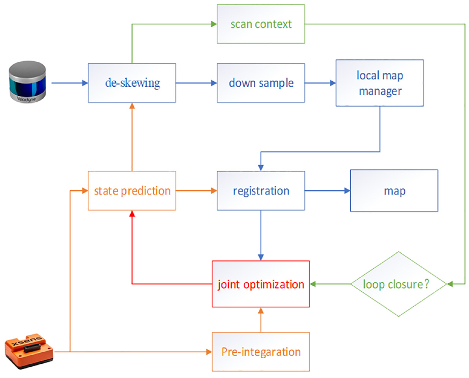
Framework diagram of the algorithm.
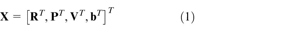
For the sake of analysis and description, the world coordinate system and the robot coordinate system are denoted as W and B, respectively. It is assumed that the IMU coordinate system and the robot coordinate system overlap in this paper. The robot state is denoted as
IMU kinematics
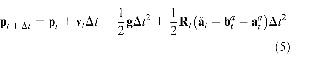
The IMU comprises an accelerometer and a gyroscope, which measure the acceleration and angular velocity of an object. By utilizing the measured data and kinematic equations, the position and attitude of the robot can be determined. However, direct integration of the raw data often results in inaccurate position and attitude estimation due to noise and bias. In this paper, the IMU measurement is defined according to equations (2) and (3), where


De-distortion and downsampling of point clouds
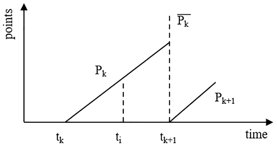
Rotating LIDAR employs a laser transmitter that rotates to emit signals into the surrounding area. These signals are then reflected by targets and collected by the receiving system. The distance to the target is determined by measuring the time it takes for the reflected signals to return. To facilitate efficient data processing, the point cloud obtained during one rotation of the LIDAR is typically released as a frame of point cloud data. The starting moment of rotation is used as the timestamp for the frame. However, due to the slow rotation speed of the LIDAR and the complex posture changes of the quadruped robot during running and jumping, the point cloud experiences significant and frequent pitch and roll angle variations, leading to severe distortion. Therefore, it is necessary to de-distort the point cloud data.
As shown in Figure 2, the end moment of the rotation is denoted as
(1) Calculate the change
(2) Determine the change
(3) Project all the point clouds under
Schematic diagram of Lidar data acquisition.
Since the LIDAR frequency is generally 10 Hz, corresponding to a rotation period of 0.1 s, assumption could be proposed that the motion of the LIDAR during one cycle is uniform. By utilizing linear interpolation, the change

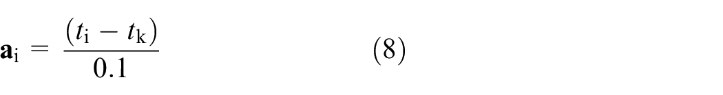
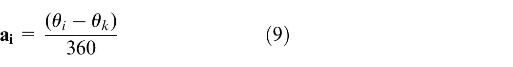
According to equations (7), (8), and (9), by finding
For a 16-line LIDAR, approximately 28,800 points are obtained per rotation. To ensure real-time operation, the single-frame point cloud is first downsampled. Voxel filtering is employed to reduce the number of points while preserving the essential features of the point cloud. This paper utilizes voxel filtering as the downsampling method for the point cloud.
3D Point cloud alignment algorithm based on normal distribution and sliding window
The 3D point cloud alignment algorithm based on Normal Distribution Transform (NDT) exhibits characteristics such as fast alignment, high robustness, and insensitivity to initial values. Compared to alignment methods such as Iterative Closest Point (ICP), the NDT-based algorithm demonstrates superior alignment performance when the quadruped robot is in vigorous motion. However, calculating laser odometry using the point cloud alignment algorithm becomes computationally intensive if performed for each frame of the point cloud. Moreover, directly aligning with the previous frame results in significant cumulative error.
To address these problems, a 3D point cloud alignment model based on normal distribution and sliding window is proposed. The algorithm encompasses the following main steps:
(1) Extraction of Keyframes: The
(2) Construction of the Local Map: Keyframes near
(3) Division of Rasters and Gaussian Distribution Construction: The 3D space is evenly divided into rasters of equal size. The point cloud corresponding to the local map
(4) Establishment of Optimization Function and Iterative Optimization: According to equation (13),

Scan context-based loop closure detection algorithm
Loop closure detection plays a crucial role in addressing the issue of position estimation drift over time by identifying the robot’s return to previously visited locations. This detection is essential for maintaining global consistency in positional estimation. In this paper, a Scan Context-based loop closure detection method is applied, which generates Scan Context descriptors by segmenting the point cloud, as illustrated in Figure 3. 12 The generation of Scan Context descriptors follows these steps:
(1) Equally divide the point cloud space into N circles along the direction of increasing radius (green arrow direction).
(2) Partition each circle into S sectors.
(3) The segmented point cloud corresponds to an
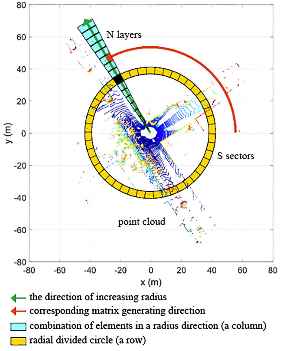
Schematic diagram of point cloud segmentation.
Upon receiving a point cloud with distortion removed, the system initially segments the point cloud and generates Scan Context descriptors. These descriptors are then inserted into a KD tree for searching and finding similarities with past descriptors. A small number of alternative descriptors are selected based on the similarity calculation. Finally, an exact similarity score is computed for each alternative descriptor, and if the score satisfies the loop closure condition, the loop closure is considered to be detected.
Factor graph-based backend optimization algorithm
In this paper, the backend optimization algorithm is implemented using a factor graph-based approach, leveraging the iSAM2 optimizer from the GTSAM library. 13 The factor graph consists of three types of factors: LIDAR odometer factors, IMU pre-integration factors, and loop closure factors. The constraint relationships among these factors are illustrated in Figure 4.
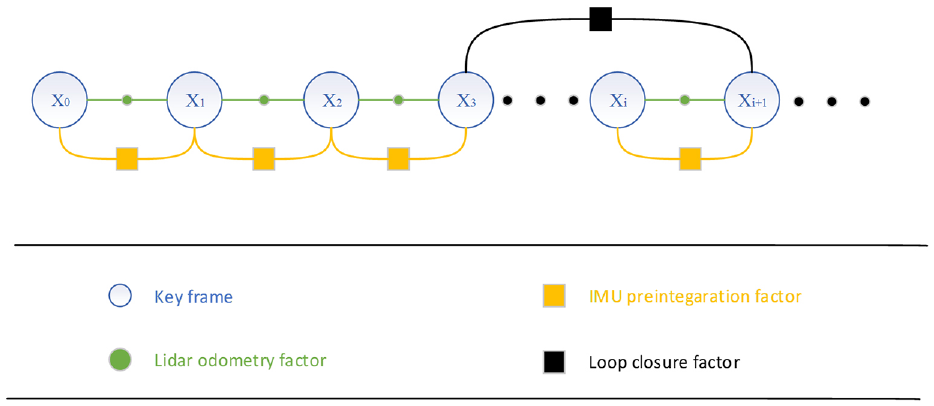
Factor graph and constraint relationship.
IMU pre-integration factor
Due to the high output frequency of the Inertial Measurement Unit (IMU), directly inserting IMU kinematic calculations as nodes into the factor graph for optimization incurs significant computational overhead. In this paper, this work is based on the adoption, proposed in this paper, of the IMU pre-integration algorithm proposed in literature.
14
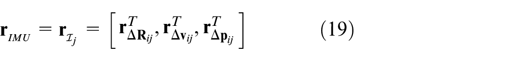
This algorithm converts the angular velocity and acceleration observations from the IMU’s high-frequency output between keyframes into bit-pose increments between adjacent keyframes. These increments constitute the pre-integration constraint factors between adjacent keyframes. The state increments


The residual term

When loop closure detection is not performed, a new least squares problem is formulated to optimize the robot state based on the LIDAR odometer factor and the IMU pre-integration factor. Specifically, the IMU pre-integration and laser odometer errors are combined by summing them according to equations (15) and (19), resulting in equation (23), where
Loop closure factor
When the system detects a loop closure, as shown in Figure 4, it identifies that key frame
Experimental analysis
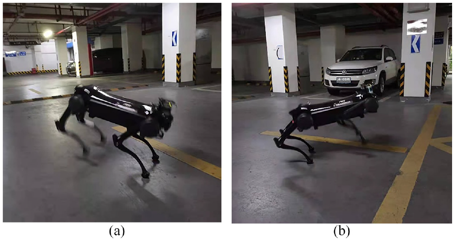
To verify the performance of the algorithms proposed in this paper, the experiment system in this work was equipped with a JueYing quadruped robot (shown in Figure 5, manufactured by Deep Robotics) carrying various sensors, including a 3D LiDAR (Velodyne VLP-16), IMU (Xsense MTI-630), and GPS-RTK (Si NanK823). The frequency of LiDAR is 10 Hz, and the frequency of IMU is 400 Hz. The robot performed data collection experiments by executing diagonal and Bound gaits, respectively. All experiments were conducted on the Robot Operating System (ROS) under Linux, running on an IPC (Intel i7-7567U, 8G memory). The map frequency of proposed algorithm is 1 Hz. Table 1 presents a comparison of the robot’s motion during data collection in Experiment 1 and Experiment 2.
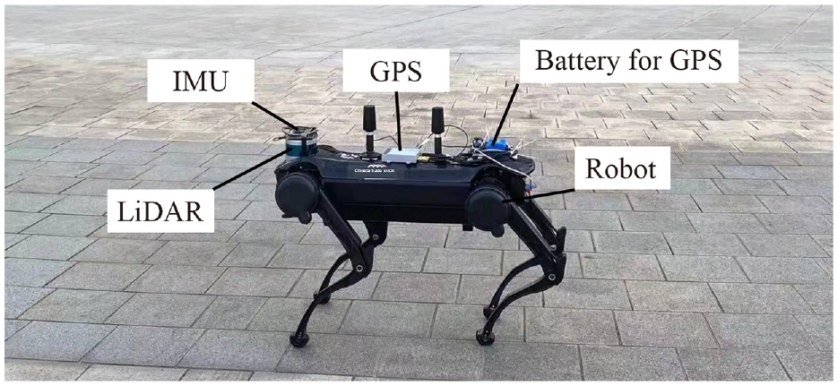
Quadruped robot physical platform.
Experiment 1 and Experiment 2 Robot motion status comparison table.
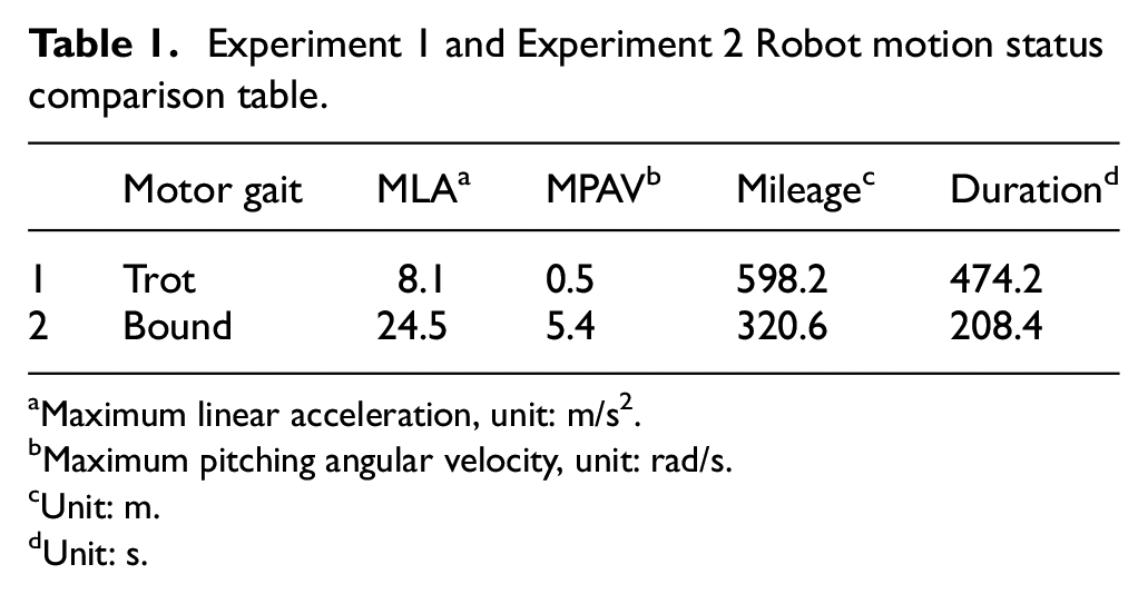
Maximum linear acceleration, unit: m/s2.
Maximum pitching angular velocity, unit: rad/s.
Unit: m.
Unit: s.
Experiment 1: Accuracy comparison
In this experiment, the quadruped robot walked around the university laboratory building using the commonly used Trot (diagonal) gait for 1 week. Data was collected using the LOAM, NDT-based SLAM algorithm, LeGO-LOAM algorithm, and the proposed algorithm. The collected experimental data was utilized to build an online map and calculate the SLAM trajectory output, which was then compared to the GPS-RTK trajectory to evaluate the error. The error evaluation metrics include maximum (max), mean (mean), median (median), minimum (min), root mean square error (RMSE), sum of squares due to error (SSE) and standard deviation (STD). Figure 6 illustrates the satellite overhead view of the experimental site, Figure 7 depicts the point cloud map generated by the algorithm proposed in this paper, and Figure 8 presents a comparison of the three algorithms and the GPS trajectory. It can be seen that LOAM exhibits larger trajectory errors, NDT shows larger elevation errors, while the algorithm proposed in this paper is consistent with the GPS trajectory. Table 2 provides a comparison of error indicators for the three algorithms, and Figure 8 presents an error line graph. Based on the experimental conditions of this paper, it can be concluded that the algorithm proposed in this paper outperforms LOAM and NDT-based SLAM algorithm in terms of all error indicators. For example, the root mean square error is reduced by 65.07% compared to LOAM,22.81% compared to the NDT-based SLAM, and 37.14% compared to the LeGO-LOAM.
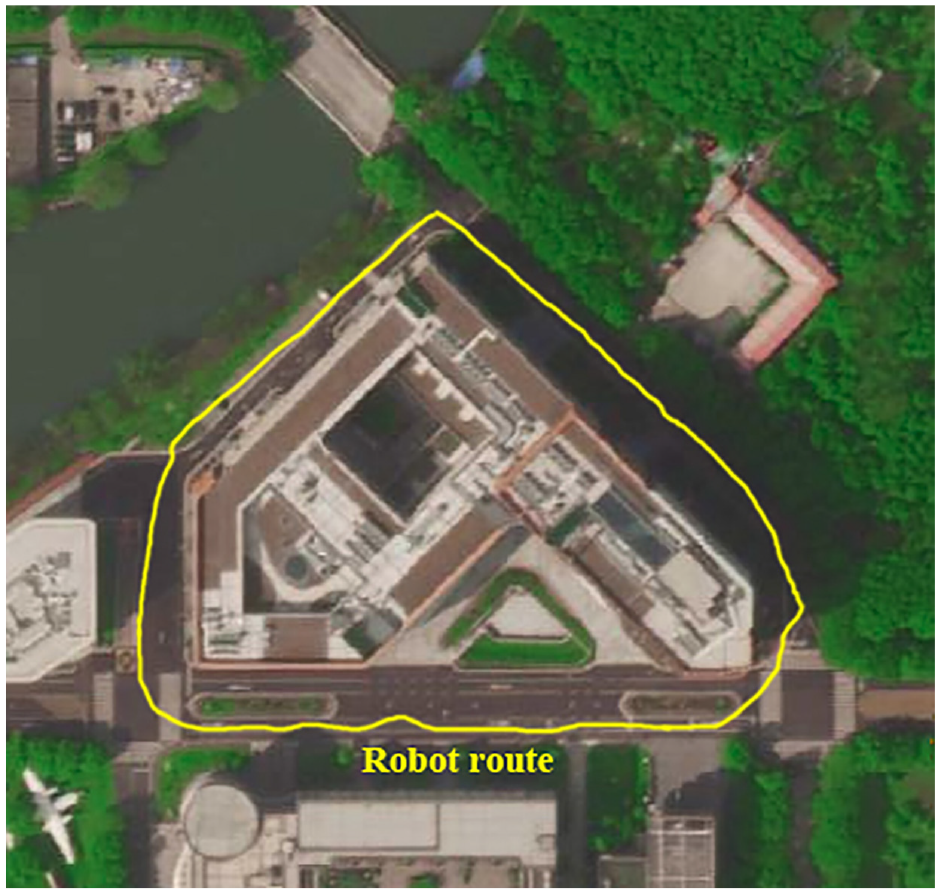
Satellite aerial view of the experimental site.
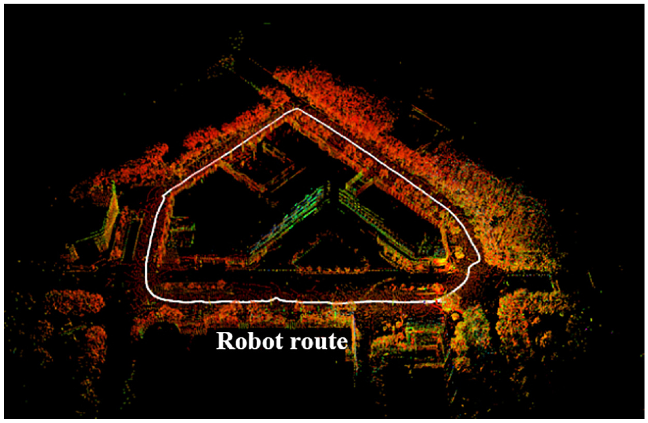
Effect of the algorithm in this paper.
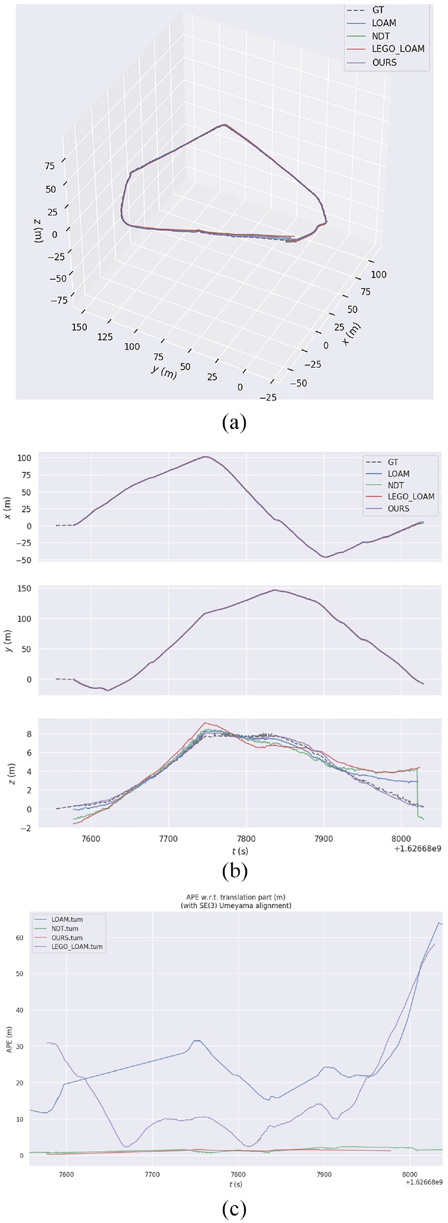
Comparison chart: (a) 3D track, (b) XYZ direction, and (c) APE (Absolute Position Error) line.
Comparison of mapping accuracy.
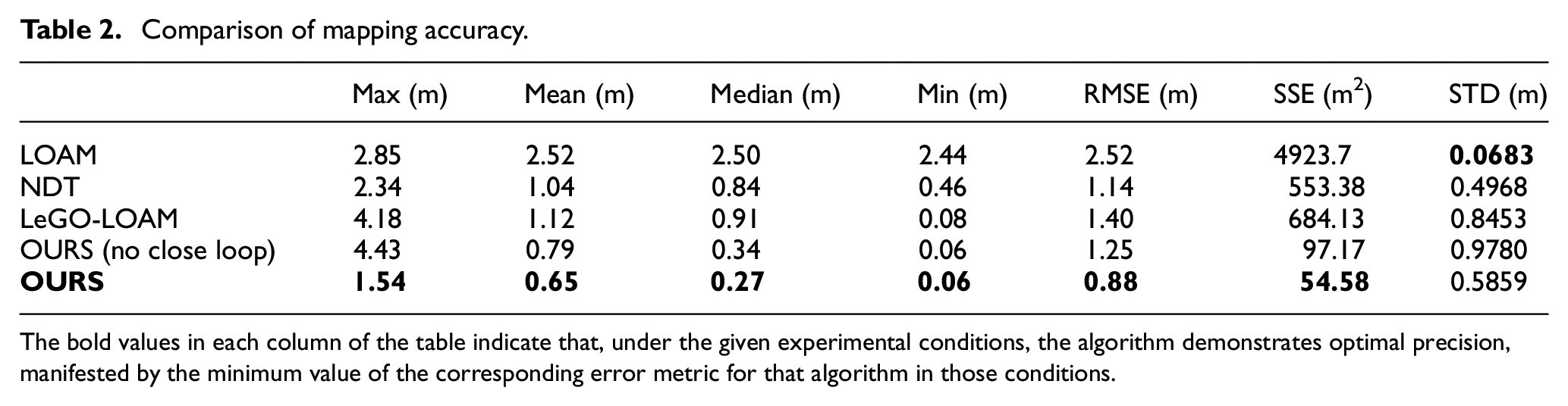
The bold values in each column of the table indicate that, under the given experimental conditions, the algorithm demonstrates optimal precision, manifested by the minimum value of the corresponding error metric for that algorithm in those conditions.
Experiment 2: Robustness comparison
The motion state of the quadruped robot executing the Bound gait is similar to that of a cheetah running, as depicted in Figure 9. The motion of the quadruped robot in this gait is vigorous and demands a high level of algorithmic robustness. In the experiments, the quadruped robot was initially controlled to traverse the school’s underground garage using the Bound gait for 1 week, during which sensor data was collected. Subsequently, the effects of LOAM, NDT-based SLAM algorithm, and the algorithm proposed in this paper were compared to construct the map based on the collected data. Since obtaining the true value of the robot’s trajectory in the Bound gait is challenging, the experiments in this paper focused on the following aspects to evaluate the algorithm’s robustness:
(1) Smooth operation of the algorithm: Algorithms with poor robustness tend to fail in map construction due to excessive drift of the localization trajectory in scenarios with violent motion.
(2) Presence of jumps in the output localization trajectory: Jumps occur when the algorithm fails to align into a local optimum.
(3) Consistency of the constructed map with the experimental site: The ground of the underground parking lot is flat, and the algorithm’s map should also exhibit a flat structure. Additionally, there are cars, columns, and other objects in the underground parking lot, and the map should be capable of clearly distinguishing these objects.
Bound: (a) Gait 1 and (b) Gait 2.
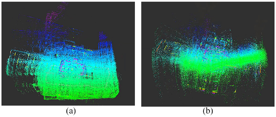
The effect of LOAM based on feature matching method is illustrated in Figure 10. The LOAM algorithm eventually fails to build a map due to significant trajectory drift. The results of the NDT-based SLAM algorithm are presented in Figure 11, the results of the LeGO-LOAM algorithm are presented in Figure 12, while the results of the algorithm proposed in this paper are shown in Figure 13. All of three algorithms operate smoothly, and according to evaluation criteria (1), the robustness of the NDT-based SLAM algorithm, LeGO-LOAM and the algorithm proposed in this paper is superior to that of LOAM.
LOAM effect: (a) mapping 1 and (b) mapping 2.
NDT effect: (a) mapping 1 and (b) mapping 2.
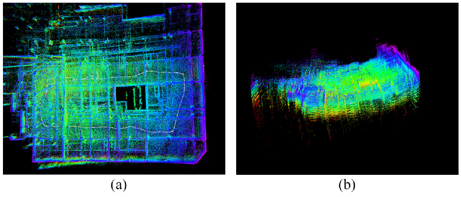
LeGO-LOAM effect: (a) mapping 1 and (b) mapping 2.
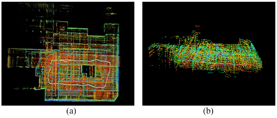
Effect of the proposal: (a) mapping 1 and (b) mapping 2.
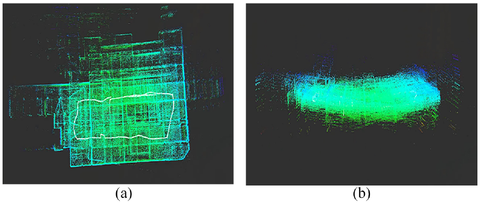
To further compare the robustness of the algorithm proposed in this paper and the NDT-based SLAM algorithm, their trajectories are derived and compared, as depicted in Figure 14. The trajectories of the SLAM algorithm exhibit significant jumps and lack order, whereas the trajectories of the algorithm proposed in this paper have no jumps and are consistent with the actual robot motion. Comparing Figures 11(b), 12(b), 13(b), and 14, it can be seen that the warping phenomenon is more pronounced in the NDT-based SLAM algorithm. Similar to LOAM, LeGO-LOAM relies on feature-based matching and is greatly affected by point cloud distortion. Despite the integration of loosely coupled IMU information, it still struggles to accurately estimate the robot’s pose, leading to significant elevation discrepancies. The map constructed by the algorithm proposed in this paper is flatter and conforms to the experimental environment. Lastly, comparing the map construction details of Figure 15(a) and (b), the map built by the NDT-based SLAM algorithm contains a considerable amount of noise and fails to distinguish objects in the surrounding environment. On the other hand, the map constructed by the algorithm proposed in this paper can clearly distinguish objects such as cars and columns, thereby aligning better with the experimental scene. In summary, based on evaluation criteria (2) and (3), the algorithm proposed in this paper exhibits better robustness compared to the NDT-based SLAM algorithm.
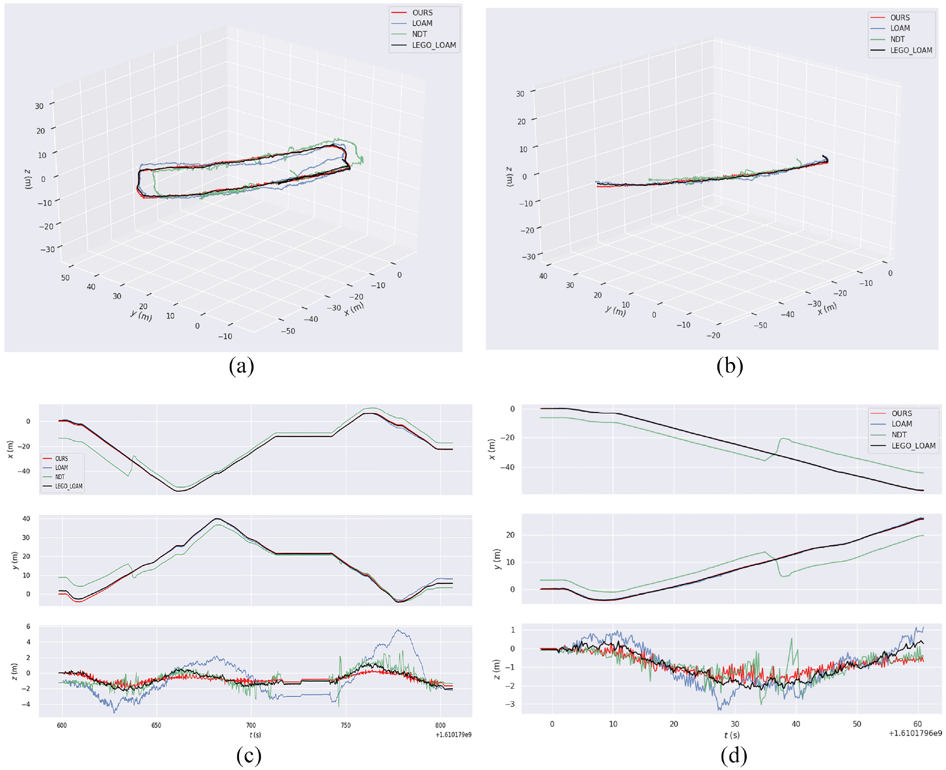
Comparison chart: (a) whole trajectory (3D), (b) first 60 s (3D), (c) whole trajectory (XYZ), and (d) first 60 s (XYZ).
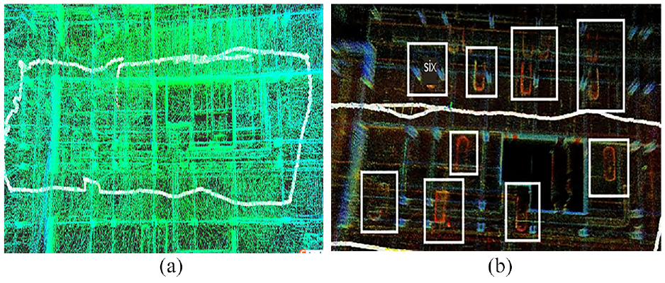
Mapping details: (a) NDT and (b) the Proposal.
Conclusion
This paper proposes a SLAM algorithm for quadruped robots with tightly coupled lidar and IMU, designs related experiments, and compares the accuracy and robustness of the existing laser SLAM algorithms. The experimental results show that the algorithm in this paper has improved significantly the accuracy compared with LOAM, NDT-based SLAM, and LeGO-LOAM algorithms. Taking root mean square error as an example, the errors are reduced by 65.07%, 22.81%, and 37.14%. At the same time, the robustness of the algorithm in this paper is also better than that of the remaining three algorithms mentioned above.
Footnotes
Declaration of conflicting interests
The author(s) declared no potential conflicts of interest with respect to the research, authorship, and/or publication of this article.
Funding
The author(s) disclosed receipt of the following financial support for the research, authorship, and/or publication of this article: Shanghai “Science and Technology Innovation Action Plan” High-tech Field Project (17511106700).