
Abstract
Maintaining exceptional product quality and boosting processing efficiency requires precise evaluation of various aspects of the turning process, including the cutting depth, feed rate, and size of the workpiece. This article presents a novel approach for observing the turning process state using modulation signal bispectrum (MSB) and motor current signals. A nonlinear model was established that clarifies the load torque oscillations during turning, which in turn affects the amplitude and phase modulation of the motor stator current. Random noise can be efficiently minimized using the MSB algorithm, allowing the extraction of the current-modulation characteristic sideband phase and amplitude from the collected current signal. This technique enables clear representation and enhanced monitoring of load torque changes throughout the turning process. The proposed method was validated via mathematical simulations and universal lathe tests, with the results indicating that the MSB phase and amplitude values effectively capture both dynamic and static torque alterations during the turning operation, making this approach a valuable tool for overseeing the turning process.
Keywords
Introduction
The domains of intelligent machining systems have a vested interest in machine-tool monitoring methodologies and proactive fault detection. One crucial machining operation is turning, a process that meticulously removes superfluous material from revolving cylindrical workpieces. Monitoring this operation is fundamental to enhancing machining quality, safeguarding expensive equipment, and guaranteeing the efficient functioning of systems. Factors such as the workpiece material, cutting tool wear, and operating environment introduce variable elements into the mechanical machining process, inducing changes over time. 1 These alterations lead to probabilistic and unpredictable scenarios during the turning process, complicating precise prediction and control. Therefore, the necessity for ultra-precise monitoring systems cannot be overstated. These systems are designed to track the myriad changes occurring throughout the turning process meticulously, ensuring precision, quality, and optimal control in machining.
At present, two primary types of approaches exist for monitoring machining conditions: direct and indirect methods. 1 In laboratories, direct measurements are generally conducted using optical sensors, 2 force sensors,3,4 and other similar techniques to assess tool wear and workpiece surface roughness; one effective method, for instance, involves utilizing a machine vision system to evaluate tool conditions.5,6 However, this approach necessitates interrupting the processing for image acquisition, limiting its applicability for online monitoring. 7 In contrast, the indirect method involves monitoring the state of the processing system by analyzing the interrelationships among various parameters, such as acoustic emission,8,9 vibration, 10 and sound. 11 Vibration sensors, commonly installed on the workpiece, are widely used in this context, but their signal amplitude varies over time during processing, adding to the complexity of the analysis.12,13 Numerous studies have demonstrated that combining multiple sensors enhances monitoring reliability and system robustness; however, these monitoring methods rely on external sensors.14–16
Changes in the processing conditions of a mechanical device, such as variations in the material or shape of the workpiece or the condition of the cutting tool, alter both static and dynamic loads on the mechanical system. Changes in torque applied to the workpiece are transmitted through the mechanical transmission system to the motor shaft; this electromechanical coupling causes fluctuations in the magnetic flux of the motor, which, in turn, induces modulation of the motor current. 17 Consequently, motor current signature analysis (MCSA) has been proposed as a method of monitoring machining processes. 18
Current signals are advantageous in monitoring machining operations due to their immunity to time-varying transmission path effects, ease of acquisition, 19 and minimal interference with the processing itself, enabling cost-effective monitoring. 20 Extensive research has been conducted to explore the relationship between current and cut force.20–23 Kuntoğlu et al. 6 employed seven different sensor types to monitor the cutting area and identified the current sensor as the third most effective in evaluating tool wear. However, utilizing the current sensor for monitoring presents challenges due to the introduction of transmission chain noise, resulting in a low signal-to-noise ratio and signal processing complexities. Consequently, the current sensor has been sparingly used (8.1%) for machining monitoring. Typically, it is combined with other sensor signals to achieve optimal performance. Nevertheless, it is suggested that the current signal, containing information about the transmission chain, can facilitate non-invasive and cost-effective global monitoring of the overall mechanical system.
To fulfill the aforementioned objectives, signal processing techniques need improvement to extract subtle signal variations and determine system state. Commonly employed methods for signal processing, including the wavelet transform, empirical mode decomposition (EMD), morphological signal processing (MSP), and spectral analysis,23–25 have been used for monitoring various aspects of machining processes, such as tool wear, 26 machine conditions, 24 and chatter.27,28 However, they suffer from limitations such as the limited length of basis functions in wavelet analysis, mode confusion in EMD, 29 and noise interference in MSP, weakening the correlation between state features and current signals. Furthermore, these methods primarily focus on amplitude diagnosis and overlook the inherent modulation characteristics of the current signal. Therefore, the nonlinear amplitude and phase interactions of the current must be described to identify small frequency variations around the power supply frequency effectively. Consequently, even slight changes in cutting parameters can impact cutting tools, workpiece size, and other relevant factors.
Bispectrum analysis, a widely employed technique for high-order spectrum analysis, utilizes third-order statistics to examine spectral characteristics and is particularly useful for detecting nonlinear and non-Gaussian systems and preserving phase information. A more precise and effective alternative to the power spectrum in analyzing modulated signals is the modulation signal bispectrum (MSB). 30 Gu et al. 31 demonstrated that the MSB enhances the complex modulation components of rotating machines, enabling more accurate diagnosis of broken rotor bars in induction motors (IMs) by detecting and quantifying sidebands in current signals, effectively mitigating random noise and interference through phase invariance and signal alignment. 32 Previous research has shown that MSB analysis is capable of early fault detection and diagnosis in various rotating machines, including reciprocating compressors, 33 rolling bearings, 34 and gearboxes. 35 However, its application in monitoring machining conditions and fault diagnosis has not been explored.
This study focuses on utilizing the amplitude and phase of the MSB to enable machining-condition monitoring, with turning experiments conducted under different machining conditions to measure instantaneous currents and extract accurate eigenvalues of states. The remainder of this paper is structured as follows. Section II introduces the proposed theoretical method. Section III presents the conclusions drawn from numerical simulations. Section IV discusses the experimental setup used to validate the proposed method. Section V presents the main findings of the study. Finally, Section VI concludes the paper.
Methodology
Turning forces
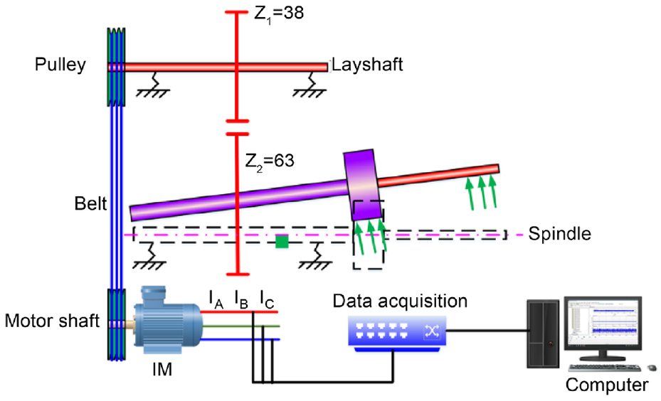
The spindle-motor drive system, a crucial mechanical component in a lathe, comprises several essential elements, including pulleys, belts, gearboxes, and spindles, all working together to ensure smooth operation. Figure 1 provides a schematic representation of the primary drive chain employed in a lathe. Variations in the process parameters, tool wear, and overall health of the machine tool can induce torque oscillations in IM, further emphasizing the importance of maintaining optimal conditions.
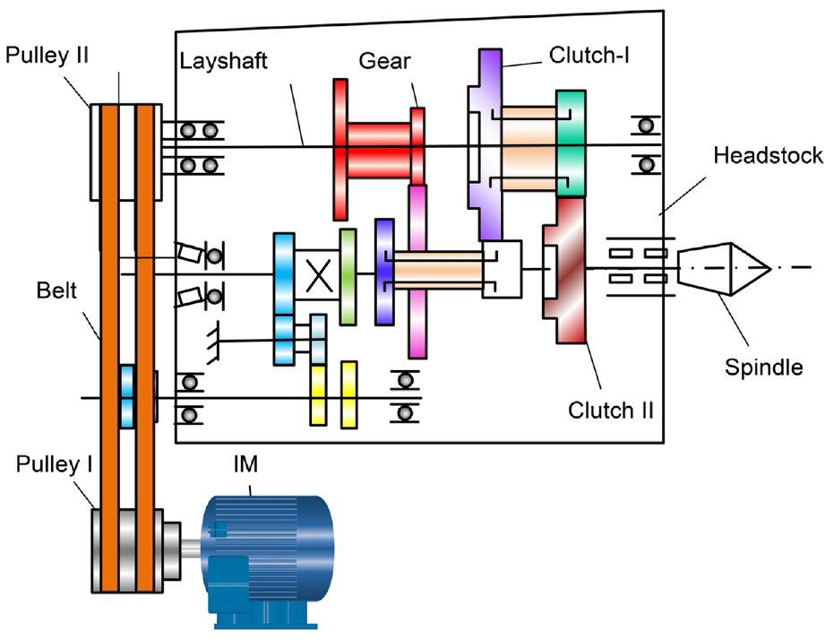
Universal lathe setup.
During lathe machining operations, the cutting forces play a significant role in determining the resistance encountered, as illustrated in Figure 2. The turning force (

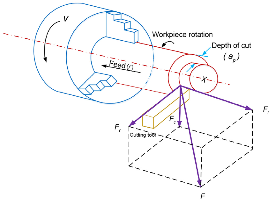
Schematic of the cutting force.
The main cutting torque is generated by

where
The cutting force can be decomposed into two distinct components – static and dynamic forces, which can be mathematically formulated as

The static component of the cutting force (
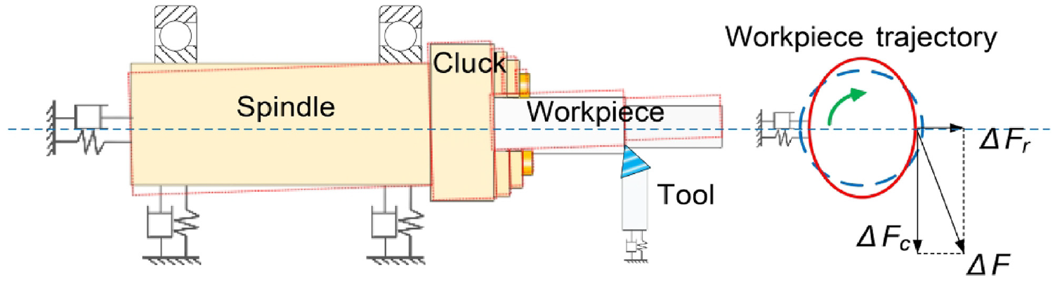
Schematic of the dynamic cutting force.
Influence of mechanical load oscillations on the current signal
The dynamic cutting force is well-known for its ability to induce fluctuations in the load torque of the IM, consequently causing variations in the load and generating oscillations in the airgap eccentricity of the IM. Such torque oscillations, arising from imbalances in the load, are typically characterized by specific frequencies often correlated with the speed of the mechanical motor. The load torque (

where

In equilibrium, the motor torque (

where
The mechanical rotor position, represented by
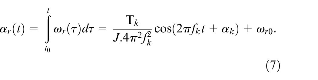
Consequently, the angular variation induces phase modulation (PM) of the magnetic flux. The magnetic flux
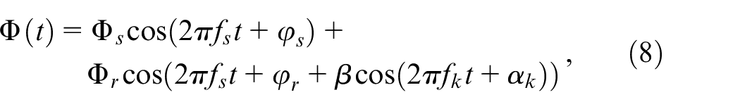
where
The relationship between stator current

Given the imposition of
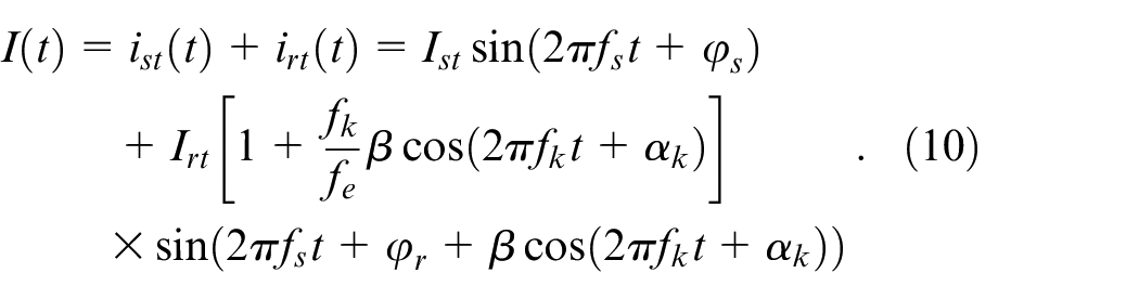
The current components of the stator and rotor, denoted by
When
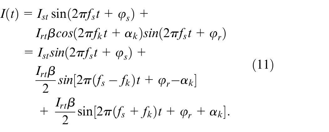
Equation (11) demonstrates that during machining operations under varying mechanical working conditions, the dynamic component causes variations in both torque and speed of the IM, leading to the appearance of additional frequencies in the current spectrum. Relevant frequency sidebands
Detection algorithm
The analysis presented in Section II B shows that the dynamic component contributes to the AM and PM of the stator current. Whereas AM results in only one pair of edge frequencies, PM leads to an “infinite” number of edge frequencies. The outcome of frequency modulation is an increase in side frequencies due to the phase difference between the PM and AM side frequency components. The coexistence of the two creates an asymmetric distribution of side frequencies.
Conventional bispectrum analysis does not adequately characterize the modulation of motor current signals. Therefore, MSB was employed in this study, calculated using the following expression 41 :

Equation (12) combines
Equation (12) can be formulated in terms of magnitude and phase in the following manner:

The MSB magnitude can then be expressed as

Simultaneously considering the variations in amplitude and phase difference of the two sidebands through MSB analysis can significantly improve the accuracy and timeliness of tool-condition monitoring and diagnosis.
The MSB phase can be mathematically expressed as

The MSB phase is independent of the fundamental frequency phase, enabling the MSB to estimate the phase without considering the fundamental frequency phase. It provides valuable information about the angular position of the modulating signal and operating parameters, independent of the starting point of the rotor angular displacement and signal acquisition. Therefore, using the magnitude and phase of MSB is a feasible means of characterizing machining conditions.
Numerical analysis of sideband responses
Due to the highly complex dynamics of motor drives, obtaining a closed analytical solution to demonstrate frequency transfer responses is challenging. Numerical simulations were conducted using a three-phase IM model, as presented in Table 1, to validate the applicability of the MSB to motor current signals in machining. The simulations were performed by solving equation (5) using the ode45 solver in MATLAB (version: R2021a).
Simulation parameters.
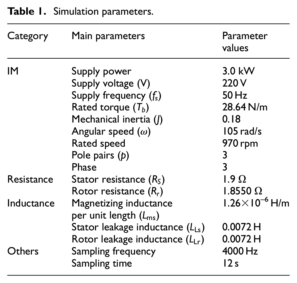
The combination of MCSA with MSB analysis was implemented under various loading conditions (10%, 50%, and 90% of Tb) to reflect different degrees of tool wear. The values 10%, 50%, and 90% of Tb correspond to light, medium, and heavy load conditions, respectively. These designations were established to facilitate comprehensive evaluation of the system. Additionally, the simulations accounted for inherent motor asymmetries. The presence of airgap eccentricity could be attributed to various factors, including manufacturing errors, unbalanced loads, bearing wear, and bent rotor shafts.
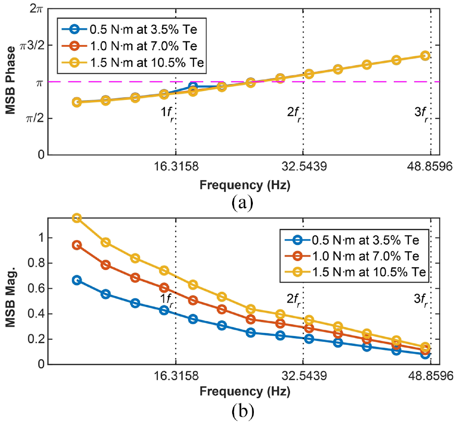
Sideband responses for static loads
First, an investigation was conducted on the variation in the static load of the motor under a dynamic force of 0.5 nm, with the analysis of MSB phase results presented in Figure 4(a). MSB phase values exhibited a proportional increase with the excitation frequency, indicating significant correlations at different frequencies. However, under different static loads (10%, 50%, and 90% of Tb), the phase trends exhibited notable shifts toward lower values. As seen in Figure 4(b), the MSB magnitudes display a significant inverse correlation with increasing frequency. Nevertheless, the values obtained under these different conditions do not exhibit substantial differences. The MSB phase demonstrates greater sensitivity to changes in the static force.
MSB phase and magnitude under different static loads: (a) phase characteristics and (b) magnitude characteristics.
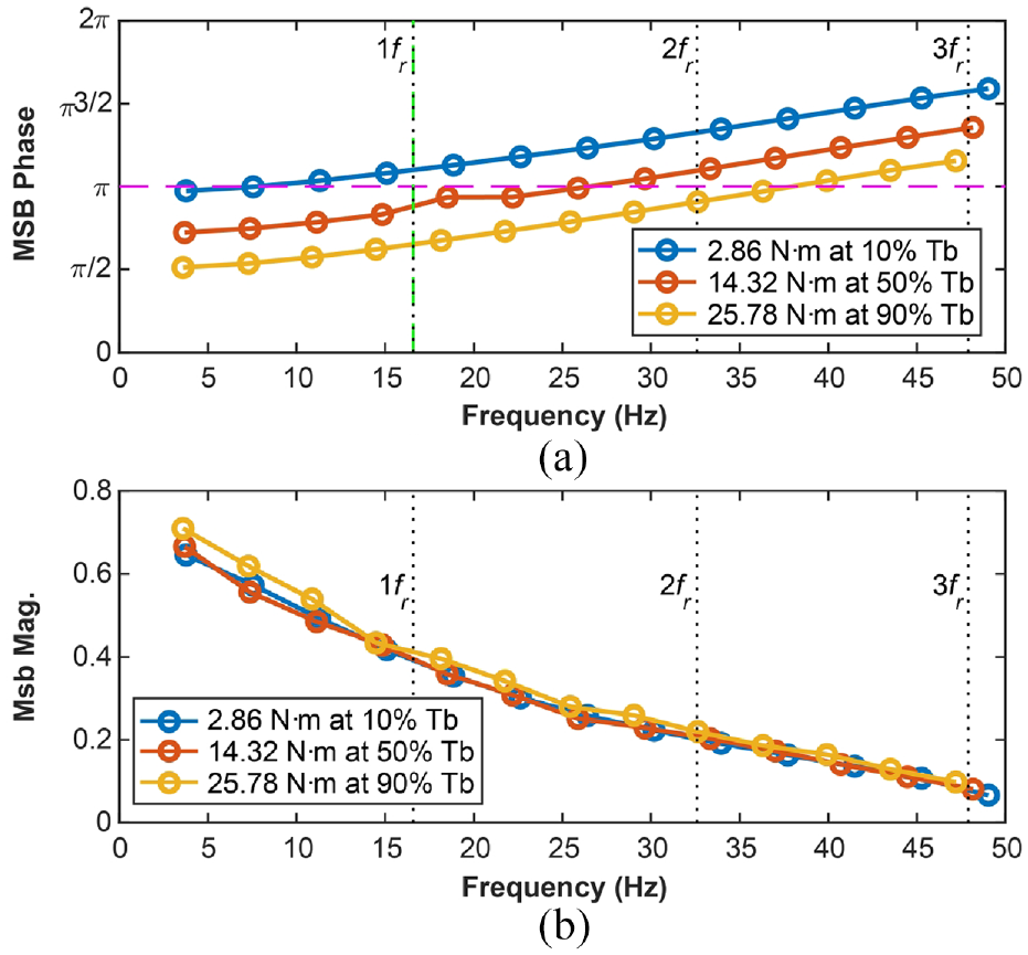
Sideband responses for dynamic loads
Next, the motor was set to operate at 50% of Tb (
MSB phase and magnitude under different dynamic loads: (a) phase characteristics and (b) magnitude characteristics.
During the turning process, fluctuations in machining parameters, tool wear, and spindle vibrations cause oscillations in the motor load. The aforementioned simulation results establish that the MSB magnitude and phase can effectively identify static and dynamic load variations in the motor, making them reliable indicators of turning conditions.
Experimental validation
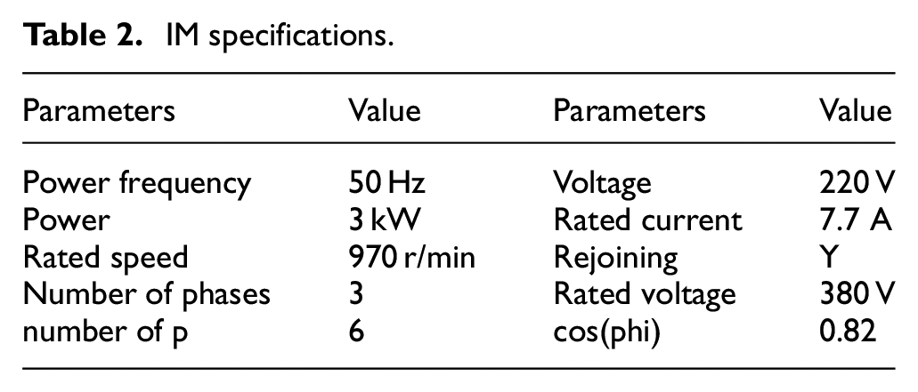
Experiments were conducted utilizing a universal lathe (CZ6132A) for shaft turning operations. To validate the analytical results and evaluate the efficacy of the proposed system for monitoring the turning process. The drive system of the lathe was powered by a three-phase IM, with all relevant parameters enumerated in Table 2. As illustrated in Figure 6, the IM propels the spindle via the belt pulley. Upon engagement of the clutch, the spindle box is actuated by the primary gear Z1/Z2, which serves dual functions of deceleration and power transmission, thereby enabling spindle rotation. Considering the working characteristics of mechanical machining and the structural composition of the cutting tool, it becomes apparent that the operational state of the driven components exerts a direct impact on the functioning status of the spindle-motor rotor assembly.
IM specifications.
Schematic of the universal lathe machining monitoring system.
To measure the motor current, a high-precision clamp meter was affixed to Phase B of the three-phase power supply of the motor. The measurement range of the current sensor extended up to 40 A, boasting an impressive accuracy of 2%, and an applicable frequency band ranging from 5 Hz to 10 kHz. The output signal from the current sensor was connected to a sophisticated data acquisition system, YMC9004, which was configured with a data accuracy of 24 bits and a sampling rate of 100 kHz.
Figure 7 presents the tool model and dimensions of the machined workpiece. The experimental parameters are documented in Table 3, which includes the spindle speed set at 1080 rpm, corresponding to a rotation frequency of 18 Hz. To assess the ability of current signal analysis in discerning different machining parameters, various DOCs were employed. Three DOCs were utilized in the experiment to match the simulation parameters. The circular shaft was subjected to turning using the RP930 general turning tool, resulting in a diameter reduction from 22 mm to 10 mm. Figure 8(a) visually displays two turning workpieces with different diameters (22 mm and 13 mm), showcasing a distinct periodic signal at 50 Hz. The spectral displays of these signals are presented in Figure 8(b), where numerous sidebands are clearly observed around 50 Hz. To identify and differentiate between these systems amid noise effectively, additional signal processing is necessary.
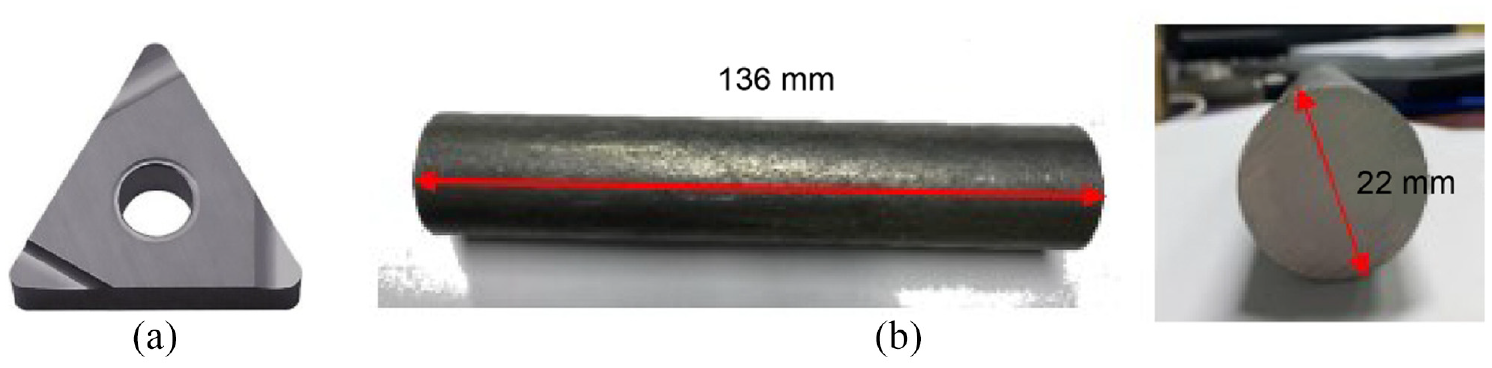
Experimental cutting tools and workpieces: (a) PR930 and (b) circular shaft.
Experimental parameters.
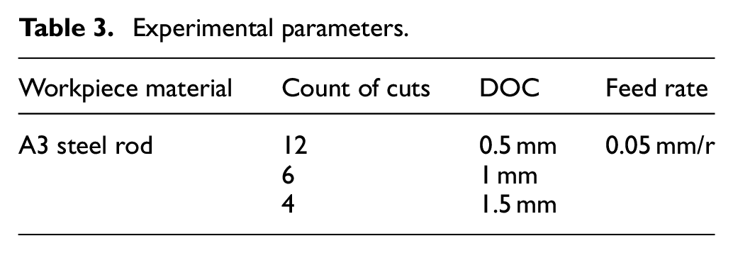
Waveforms and spectral comparisons: (a) time-domain waveform and (b) frequency-domain waveform.
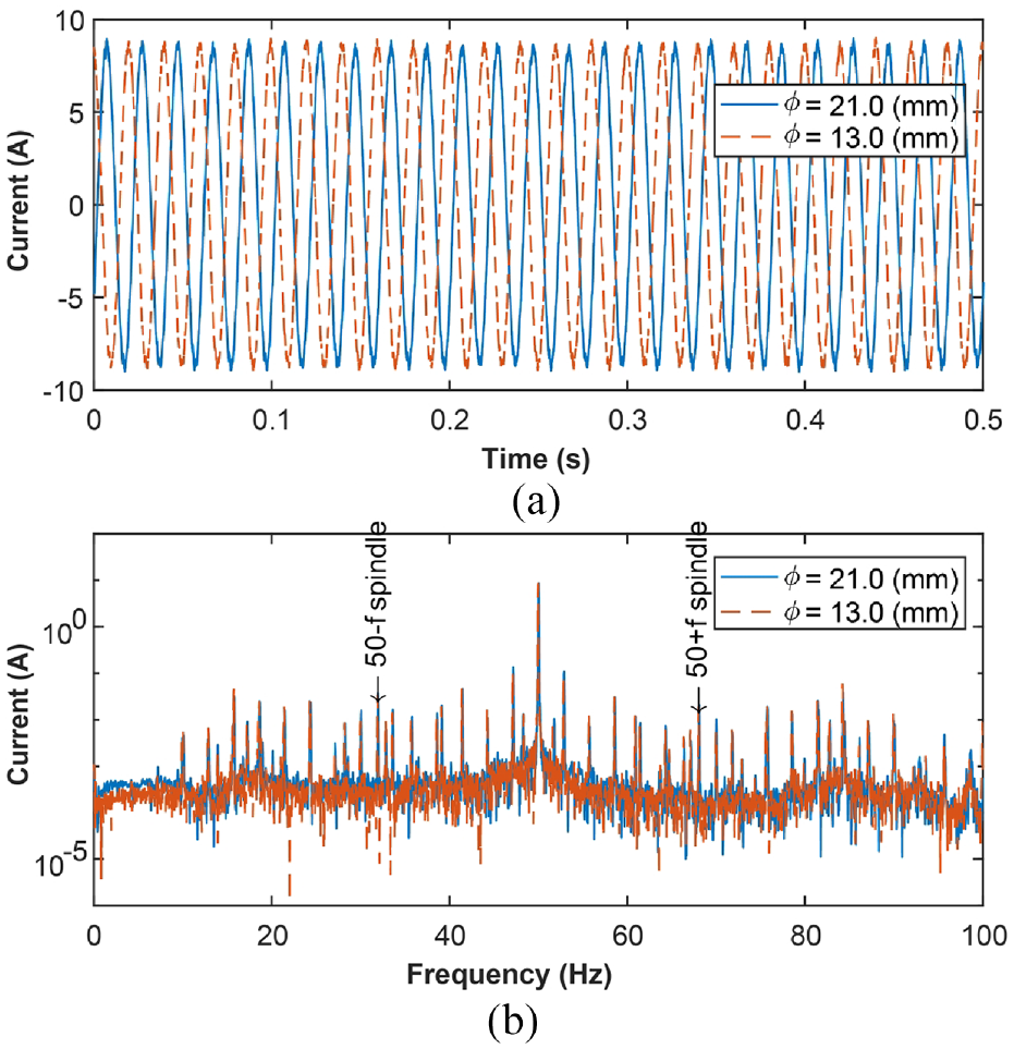
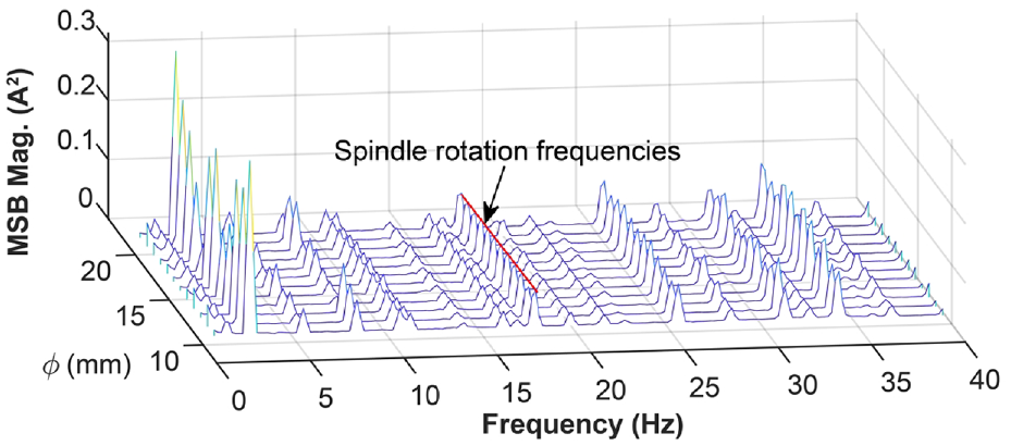
To validate the proposed method, the data underwent further processing using the algorithm described in Section II C. The Hanning window was employed to mitigate spectrum leakage in the data frames. Interference suppression involved a 40% overlap of frames, with an average of 100 calculations performed. Figure 9 illustrates typical calculation results, demonstrating that the magnitudes of the MSBs are predominantly concentrated in the frequency slice at
MSB analysis results (DOC = 0.5 mm, diameter = 13 mm).

MSB magnitudes for
The remaining frequencies shown in Figure 10 correspond to the rotations of the lathe spindle, motor shaft, and layshaft. Changes in these frequencies serve as indicators for the turning process. The amplitude at DOC = 1.0 mm is higher compared to that at DOC = 0.5 mm. The MSB results encompass ample information to reflect the machining conditions. To achieve a comprehensive monitoring analysis across various DOCs and workpiece diameters, the MSB analysis was employed to extract the magnitudes of MSB at critical frequencies. Figure 11 presents the 50 Hz slices of the MSB for different workpiece diameters (with DOC = 0.5 mm). Given the pivotal role of the spindle in driving the workpiece rotation, its rotation frequency serves as a key indicator of the overall machining state. Consequently, this feature was extracted for detailed comparative analysis.
MSB magnitude slices for DOC = 0.5 mm.
MSB phase results
Figure 12 presents the monitoring outcomes acquired from the MSB phases. As anticipated, the MSB phase values exhibited a increase in response to decreasing DOC and workpiece diameter, reinforcing the simulation outcomes discussed in Section III A. As per Section II C, the MSB phase values remain unaffected by the fundamental frequencies, indicating that during machining, the phase values are associated with the static component of the turning process.
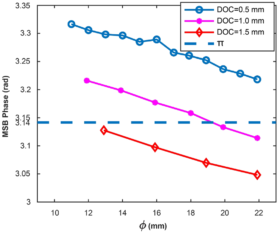
MSB phases for different DOCs.
The predominant influence on the cutting force trend is the quasi-static component, which mirrors alterations in the cutting force needed by the tool to extract metallic material from the workpiece surface. This metallic material mainly stems from the machining parameters and tool wear. Furthermore, equation (2) illustrates a significant correlation between the quasi-static component and the cutting parameters (
MSB magnitude results
Due to the direct impact of cutting force/torque on the spindle, the rotational frequency of the spindle was derived through frequency analysis. Figure 13 illustrates the magnitude results at the designated spindle frequency, effectively demonstrating the variation in the DOC. In the case of precision machining with a DOC of 0.5 mm, the magnitude results obtained from the MSB failed to differentiate between changes in machining diameter accurately, consistent with the numerical analysis presented in Section III B, indicating that the magnitude is influenced by both static and dynamic loads. However, its sensitivity to static loads is not significantly high, with its primary feedback mechanism pertaining to dynamic loads.
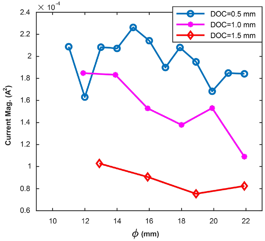
MSB magnitudes for different DOCs.
The dynamic cutting force has a negligible impact on the overall cutting force and exhibits a weak correlation with cutting process parameters. The dynamic component is intricate, and irregular wear of the cutting tool introduces dynamic and stochastic elements to the turning force. The system vibration further contributes to these dynamic components. Consequently, the magnitudes associated with the MSB serve not only to monitor changes in cutting parameters during rough machining but also as indicators for identifying abnormal system vibrations or anomalous tool wear.
The MSB phase results are highly sensitive to turning parameter variations and strongly correlate with machining parameters. These phase results mainly detect static changes in load, capturing the quasi-static elements of the turning process, such as machining parameters, tool wear, and cutting force changes. On the other hand, the MSB magnitude results, which are sensitive to turning parameter fluctuations and influenced by both static and dynamic loads, track variations in rough machining parameters and pinpoint unusual vibrations. In essence, the MSB is used to monitor changes in motor load conditions caused by factors such as tool wear, motor asymmetries, and system dynamics changes. It is also instrumental in distinguishing and identifying various machining states and conditions.
Comparison analysis
To analyze static loads, the root-mean-square (RMS) current is typically evaluated. Figure 14 displays the results of the current RMS analysis for different machining parameters. The RMS method effectively identifies changes among different DOCs, but it does not account for variations in the workpiece diameter.
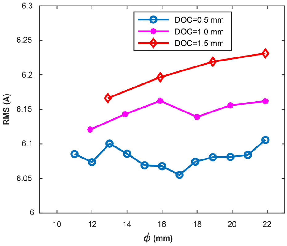
RMS results for different DOCs.
An envelope spectrum analysis was employed to identify variations in dynamic loads, as depicted in Figure 15. The results showed significant fluctuations near the spindle frequency. The envelope spectrum results indicate system dynamic loading variations. However, significant background noise precludes the use of spindle frequency amplitude from the envelope spectrum as a machining state indicator.
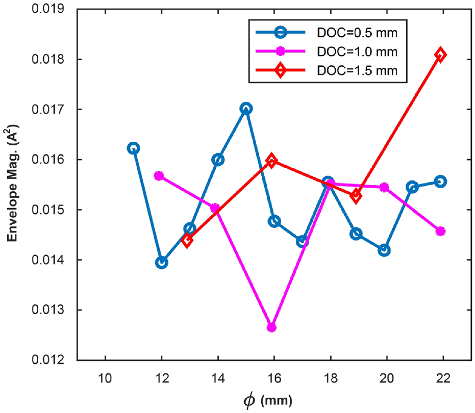
Envelope results for different DOCs.
The findings demonstrated that the MSB analysis suppresses system interference and reduces high background noise caused by transmission chains. Consequently, it provides reliable indicators for accurately assessing the machining status.
Conclusion
This study comprehensively investigated the effectiveness of MCSA with MSB analysis for detecting different machining states using theoretical analysis, numerical simulations, and experimental evaluations. Our experimental results demonstrated that the phase component of MSB analysis predominantly reflects variations in the quasi-static load, rendering it highly responsive to changes in the machining parameters. This sensitivity enables it to signal variations in the cutting depth and diameter to machinists effectively. In contrast, the magnitude component of MSB analysis, although less sensitive to the machining parameters, relies on both static and dynamic loads. Its sensitivity to dynamic load changes makes it suitable for monitoring system health. In particular, it can detect abnormal wear of turning tools and the presence of abnormal vibrations in the system.
Nonetheless, this study has certain limitations. Although the MSB provides comprehensive insights, refining its resolution could enhance its efficiency. Moreover, variabilities stemming from diverse operating settings or material traits could influence MSB outcomes, signifying the potential for expansive real-time assessments.
Footnotes
Acknowledgements
None.
Declaration of conflicting interests
The author(s) declared no potential conflicts of interest with respect to the research, authorship, and/or publication of this article.
Funding
The author(s) disclosed receipt of the following financial support for the research, authorship, and/or publication of this article: This work was supported in part by Open Fund Project of Key Laboratory of Science and Technology on Integrated Logistics Support under Grant 20210804023 and in part by Guangdong Basic and Applied Basic Research Fund Offshore Wind Power Scheme-General Project under Grant 2022A1515240042.