
Abstract
The formed surface quality of metallic sealing ring of aero-engine affects the aircraft service performance directly. However, existing inspection methods, such as the final destructive inspection and the line laser scanner section profile measurement, only evaluate the formed quality from a 2-D view, that is, single or multiple radial formed section profiles. The lack of geometric information of 3-D surface is not conducive to the comprehensive monitoring of forming quality and process planning. Therefore, based on the line laser scanners, this paper mainly proposes a vibration errors compensation method based on self-feature registration. Aiming at the problem of rigid transformation of the measurement profile caused by random vibration during the rotary motion of metallic sealing ring, the feature of measurement profile in stationary scene (MPSS), that is, the medial axis, is used as the reference for the correct pose of measurement profile. The principle of finding the correct pose of measurement profile in rotary motion scene (MPRMS) is to minimize the distance between the medial axes. Next, based on the rotary motion information of metallic sealing ring and the geometric information of measurement system, a 3-D reconstruction matrix is built, so as to convert each measurement profile to the base coordinate system in turn, and finally a 3-D dynamic measurement method for the metallic sealing ring forming surface is built. The effectiveness of the proposed method is verified through simulation experiment and real measurement.
Keywords
Introduction
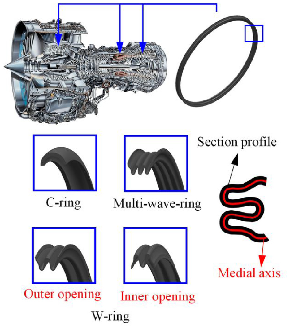
Metallic sealing ring is a key part widely used in aero-engine system, 1 its surface formed quality directly affects the sealing effect and plays an important role in the safe service of aircraft. To meet the sealing needs of different cases, metallic sealing rings have a variety of section forms, mainly divided into C-rings, W-rings (inner and outer openings), and multi-wave-rings. Due to the complex section, small size, overall ring closed, etc., metallic sealing rings are difficult to inspect. In the past decades, the formed result of metallic sealing ring heavily relied on the final destructive inspection, which involves randomly sampling from the same batch of products, cutting the rings radially, and scanning the section to obtain inspection results. The lack of inspection means in the forming process makes it difficult to find forming defects in time. In recent years, optical measurement has been widely used by virtue of its flexibility, portability, and high measurement accuracy. 2 In the work, 3 the non-destructive, on-machine measurement of the inner and outer radial section profiles of the metallic sealing ring is realized by means of two line laser scanners. However, the current works only evaluate the formed quality of metallic sealing ring from a 2-D view, that is, single or multiple radial formed section profiles, the lack of geometric information of 3-D surface is not conducive to the comprehensive monitoring of forming quality. Therefore, the 3-D measurement of the metallic sealing ring forming surface is very significant to provide support for process planning, and contributes to lower scrap rates and reduced production costs.
Although the measurement data of the on-machine measurement based on laser scanners is section profile point cloud, the metallic sealing ring rotates around its own axis during the forming process. Therefore, 3-D dynamic measurement of surface can be achieved with the help of the self-rotary motion. The 3-D dynamic measurement of surface mainly involves two aspects: 3-D reconstruction and dynamic measurement. The former works are represented by multi-view registration, where the measurement point clouds from different views are aligned to the common coordinate system, so as to achieve object reconstruction, such as aero-engine blade, 4 wind turbine blade, 5 but the sensor and the object are often stationary when performing fixed point measurements in different views. The latter is to measure the profile of object during its motion (some scenes for sensor motion). In motion scene, the decrease of measurement data precision and the relative random vibration between measurement object and sensor present new challenges, and dynamic measurement has thus become a technical challenge. For improving the measurement data precision, Pan et al. 6 built an online dynamic wheel size measurement method based on multisensory data fusion, the measurement mode is through multiple sets of data, with the shape-constant characteristics of a wheel body, which can remove measurement noise and fill up the missing data. Liu et al. 7 proposed an on-machine measurement method for out-of-round of wheel profile, a dynamic measurement model is built to separate wheel profile from the measurement data. In the dynamic measurement of rail profile, the random vibration between the laser sensor and the rail can cause the optical plane to be not parallel to the section profile of the rail, resulting in measurement profile distortion. Wang et al. 8 analyzed the triple primitive of the geometric difference between the positive and distorted section profiles, by constructing the coordinate set from the distorted profile projection to the standard profile, the self-compensation of the iterative external camera parameters attached to the predefined measurement coordinate system is realized, so as to ensure the light plane are parallel. Sun et al. 9 obtained the rail section profiles by a multi-line structured-light vision sensor, each profile can be segmented into two curves, one represents the rail waist is used to fit the rail longitudinal axis and establish an auxiliary plane perpendicular to the direction, the deviation rectifying process is to project the rail section profiles onto the auxiliary plane, to recover perpendicularity between the light plane and the rail. In addition to distortion, the random vibration associated with the motion also cause rigid transformation of the measurement profile (i.e. rotation and translation). Lim et al. 10 utilized the overlaps of the dual lasers after projection and measured the height difference between the objects to calculate the vibration errors. However, the method achieves vibration errors compensation in the vertical direction only. In summary, the work on dynamic measurement of geometric profile is less, and the lack of a dynamic measurement method under the rotary motion of ring part makes it impossible to accurately measure the 3-D surface. Therefore, this paper carries out the vibration errors compensation for the problem of rigid transformation of the measurement profile caused by random vibration during the rotary motion of metallic sealing ring, in order to realize 3-D dynamic measurement of surface.
In this paper, a vibration errors compensation method is proposed, so as to rigidly transform the measurement profile to the correct pose. Vibration errors compensation can be transformed into a registration problem, which is divided into two steps: (1) Determine the correct pose of the measurement profile in the motion scene; (2) Calculate the rigid transformation between the current pose and the correct pose of the measurement profile. However, the correct pose of measurement profile is unknown and the rigid transformation cannot be calculated. One method is to assume that the measurement profile in the stationary scene (MPSS) is the reference for the correct pose of the measurement profile in the rotary motion scene (MPRMS), then, the MPRMS is transformed to the reference by registration. In the above method, the assumption of correct pose does not provide evidence, the principle of finding the correct pose of the MPRMS is to minimize the distance between the measurement profiles, which may not be true. Therefore, how to define the correct pose and find the correct pose of MPRMS is the key to solve the above problems. In the section profile of metallic sealing ring, there is a special feature: the medial axis. As shown in Figure 1, the medial axis has the property of equal distance from each point on the line to the inner and outer profiles. The 3-D CAD model of metallic sealing ring is obtained by rotating the 2-D section profile in fixed axis, in the forming process, the roundness is controlled by the flexible restraint rollers, which is easier to control than the section shape, and when there are shape differences between the section profiles of the actual formed part, align the medial axes of measured profiles is more in line with the fact. Therefore, the medial axis of MPSS is used as the reference for the correct pose of MPRMS, and the principle of finding the correct pose of MPRMS is converted to minimizing the distance between the medial axes. After completing the vibration errors compensation, a 3-D reconstruction matrix is constructed based on the rotary motion information of metallic sealing ring and the geometric information of measurement system, and each measurement profile in the measurement coordinate system is sequentially transformed to the base system. Finally, a 3-D dynamic measurement method for metallic sealing ring forming surface is built. The main contribution and significance are as follows:
(1) Based on the laser scanners, a 3-D dynamic measurement method for metallic sealing ring forming surface is proposed, which supports the comprehensive monitoring of the forming quality, and provides a reference for the 3-D dynamic measurement of ring part surface under the rotary motion.
(2) A vibration errors compensation method based on self-feature registration is proposed. The Voronoi diagram is used to extract the medial axis of the section profile, the medial axis of the MPSS is used as the reference for the correct pose of measurement profile. The principle of finding the correct pose of the MPRMS is to minimize the distance between the medial axes, which effectively solves the problem of measurement profile transformation due to the random vibration associated with the rotary motion of the metallic sealing ring.
(3) The validity of the above methods are verified by simulation experiments, the real measurements provide a feasible example for comprehensively monitoring the forming quality of metallic sealing ring.
Metallic sealing ring and self-feature: medial axis.
The rest of this paper is organized as follows. In Section 2, the measurement system and problem are introduced. In Section 3, the vibration errors compensation method and the 3-D reconstruction method of surface is described in detail. Section 4 presents the simulation experiments, real measurement and corresponding results discussion, and Section 5 concludes this paper.
Measurement system and problem
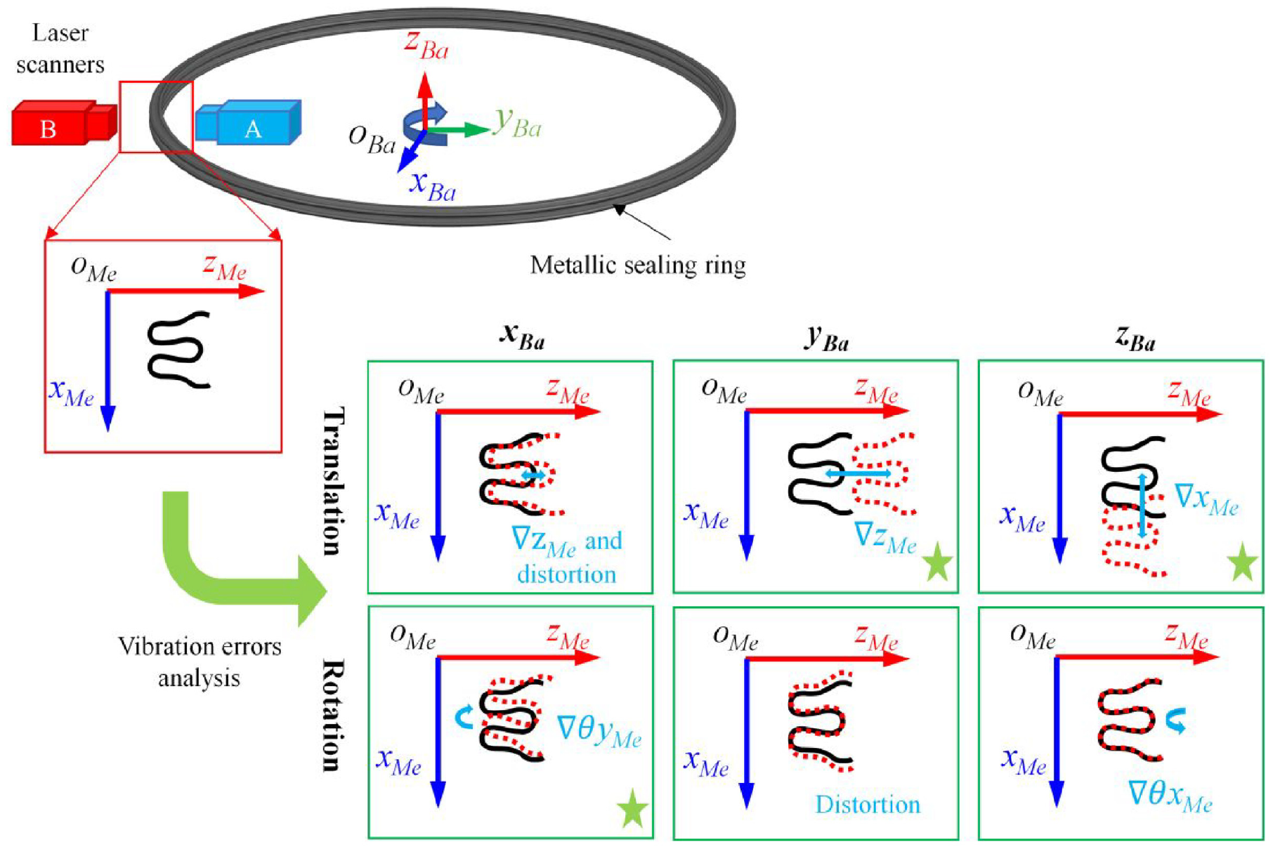
The schematic diagram of on-machine measurement system of metallic sealing ring is shown in Figure 2. The two laser scanners measure from the inner and outer sides of the radial section profile of the ring, and their optical planes are aligned to ensure that the measured section is the same. During the forming process, the metallic sealing ring rotates around its own axis, and the 3-D dynamic measurement of surface can be realized by the self-rotary motion. However, the random vibration during the rotary motion of the ring leads to rigid transformation of the measurement profile in measurement coordinate system, the measurement profile deviates from the correct pose, that is, it generates rotation and translation, resulting in vibration errors. Therefore, it is necessary to compensate for vibration errors, in other words, the measurement profile is transformed to the correct pose.
On-machine measurement system schematic diagram and vibration errors analysis.
In the following, the vibration errors analysis is given. Define the base coordinate system oBa-xBayBazBa and the measurement coordinate system oMe-xMeyMezMe, as shown in Figure 2. The axis of the metallic sealing ring is located on the zBa axis of the base coordinate system oBa-xBayBazBa, and the axis of the metallic sealing ring is ensured to be co-linear with the zBa axis by means of flexible clamps and restraining rollers. The xMe-zMe plane of the measurement coordinate system oMe-xMeyMezMe, the radial measurement section of the metallic sealing ring and the yBa-zBa plane of the base coordinate system are coplanar. The yBa axis is co-linear with the zMe axis. During the forming process, the metallic sealing ring is rotated around the zBa axis, and its radial section profiles pass through the xMe-zMe plane in turn, while the effect of random vibration associated with the rotary motion will be directly reflected in the xMe-zMe plane.
Decompose random vibration into three translational axes and three rotational axes. The translational vibration of xBa axis will cause the measurement profile to be non-radial, the measurement profile in xMe-zMe plane will be distorted and the translation in zMe axis direction will be generated. The rotation vibration of xBa axis will cause the measurement profile to rotate in xMe-zMe plane. The translational vibration of yBa axis will cause the measurement profile to translate in zMe axis direction. The rotation vibration of yBa axis will cause the measurement profile to be non-radial, the measurement profile in xMe-zMe plane will be distorted. The translational vibration of zBa axis will cause the measurement profile to translate in xMe axis direction, and the rotation vibration of zBa axis is the same as the rotation direction of the metallic sealing ring.
In summary, the rotation vibration of xMe-zMe plane, the translational vibration of yBa axis and the translational vibration of zBa axis will lead to a rigid transformation of the measurement profile in the measurement coordinate system, that is, the translation in two directions and the rotation in xMe-zMe plane. This paper focuses on compensating the vibration errors in the three directions mentioned above, and finally develops a 3-D dynamic measurement method for the metallic sealing ring forming surface.
The 3-D dynamic measurement method
Method overview
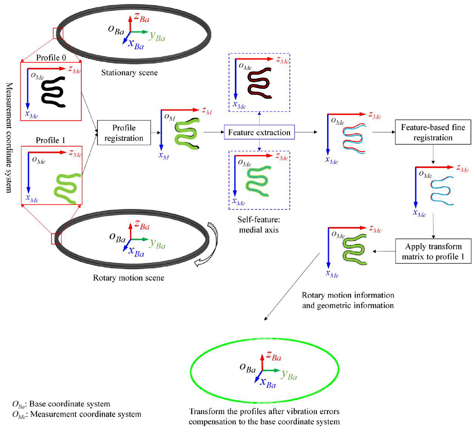
The 3-D dynamic measurement method for the metallic sealing ring forming surface mainly includes: (1) Vibration errors compensation; (2) 3-D reconstruction of surface. Assume that K section profiles are measured during a one-cycle of metallic sealing ring, denoted as Profile 0, Profile 1, …, and Profile K-1. Profile 0 is collected in stationary scene, while the remaining K-1 profiles are collected in rotary motion scene. The 3-D dynamic measurement method is shown in the Figure 3, take Profile 0 and Profile 1 as examples, the basic steps are as follows:
Step 1: Vibration errors compensation based on self-feature registration.
Step 1.1: Profile registration. Based on rigid registration, Profile 1 is rigidly transformed to Profile 0 to achieve optimal alignment between the two.
Step 1.2: Feature extraction. Extract the self-features of Profile 0 and Profile 1 based on Voronoi diagram, that is, medial axes.
Step 1.3: Feature-based fine registration. The transformation matrix is obtained by rigidly registering the medial axis of Profile 1 to the medial axis of Profile 0, and apply it to Profile 1, Profile 1 is transformed to correct pose.
Step 2: 3-D reconstruction of surface. Based on the rotary motion information of metallic sealing ring and the geometric information of measurement system, a 3-D reconstruction matrix is constructed, and transform the Profile 1 compensated for vibration errors in the measurement coordinate system to the base coordinate system.
Step 3: Perform the above steps on the measured Profile 2, …, and Profile K-1, to achieve the 3-D dynamic measurement of surface of metallic sealing ring.
The 3-D dynamic measurement method for the surface of metallic sealing ring.
Vibration error compensation
In the section profile of metallic sealing ring, there is a self-feature called medial axis, the medial axis has the property of equal distance from each point on the line to the inner and outer profiles, when the thickness of each radial section of the metallic sealing ring is different, align the medial axis of each measured profile is more in line with the fact. Therefore, the medial axis of the MPSS is used as the reference for correct pose. The principle of finding the correct pose of the MPRMS is to minimize the distance between the medial axes. The vibration errors compensation based on self-feature registration mainly includes two parts: registration and self-feature extraction.
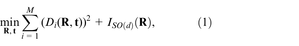
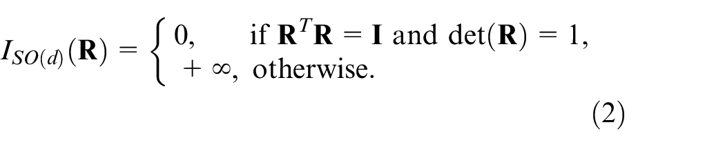
In vibration errors compensation, a total of two registrations are performed. The first registration is profile registration, and the second registration is feature-based registration. The purpose of profile registration is to provide initial pose for feature-based registration to obtain accurate results. Due to the data form of measurement profile is point cloud, the registration is point-to-point, and both registrations use the iterative closest point (ICP) algorithm.11,12 ICP is a classical rigid registration algorithm, which alternates between closest point query in the target set and minimization of distance between corresponding points, and is guaranteed to converge to a locally optimal alignment.
13
Define the point cloud of MPSS as
where
Equation (1) is solved by alternating between the correspondence step and alignment step. In the correspondence step, find the closest point
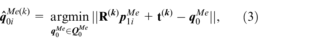
in the alignment step, update the transformation by minimizing the distance between the corresponding points:
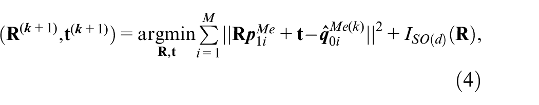
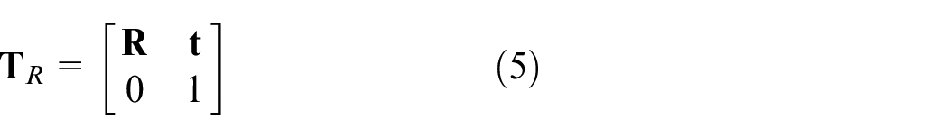
the alignment step can be solved in closed form by singular value decomposition (SVD). Finally, the rigid transformation matrix
In the self-features extraction, select the medial axis of the section profile of the metallic sealing ring for self-feature. The extraction methods of medial axis mainly include Topological Thinning, Distance Transform and Voronoi diagram.
14
Among them, the Topological Thinning and Distance Transform are mainly used for the extraction of medial axes of objects represented by pixels or voxels. Voronoi diagram is a geometric structure that divides spatial regions, take

where,
As shown in Figure 4, the basic steps are as follows:
Step 1: Profile division. Based on the maximum and minimum points in the xM axis direction of the measurement coordinate system,
Step 2: Calculation of Voronoi vertices. Perform Delaunay triangulation on
Step 3: Extract medial axis. Firstly, extract the union of
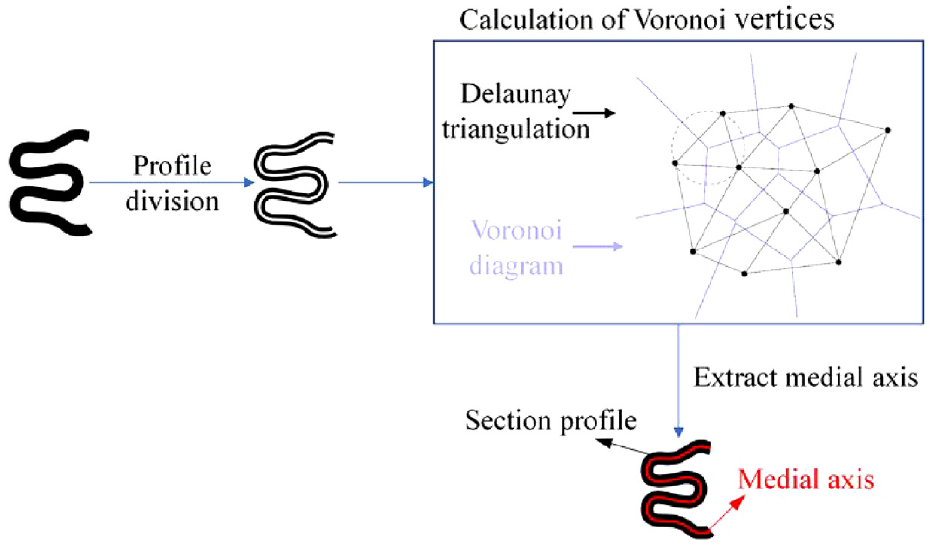
Self-features extraction.
The 3-D reconstruction of surface
After completing the vibration errors compensation, each measurement profile is still located in the measurement coordinate system. Therefore, based on the rotary motion information of metallic sealing ring and the geometry information of measurement system, a 3-D reconstruction matrix is built, and the measurement profiles are transformed into the base coordinate system to obtain the 3-D surface.
As shown in Figure 5, the rotary motion information is the rotation angle of the metallic sealing ring relative to the initial position. When the kth measurement profile is collected, the rotation angle is expressed as:

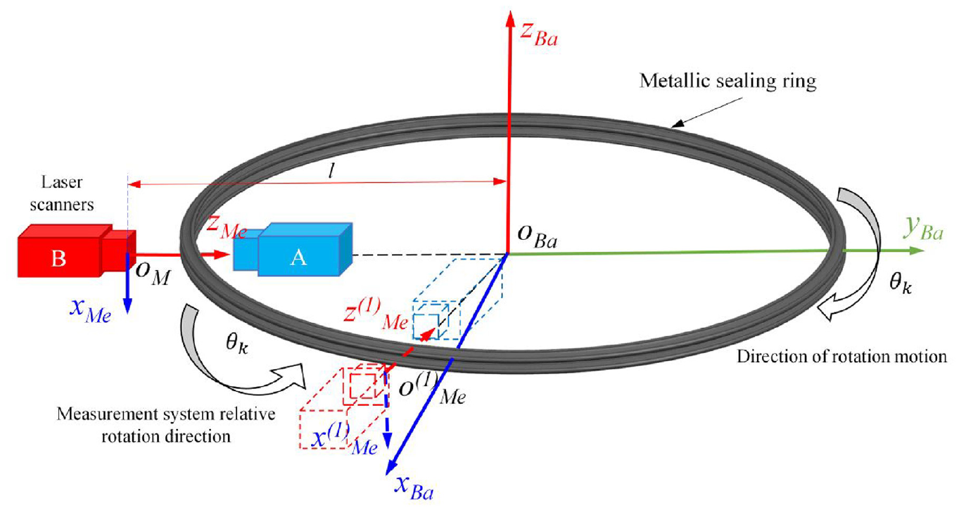
The schematic diagram of 3-D reconstruction.
the geometric information of the measurement system is the distance l between the origin oMe of measurement coordinate system and the origin oBa of base coordinate system, which can be obtained by calibration. Therefore, according to the coordinate transformation method 16 and Figure 5, the 3-D reconstruction matrix is:
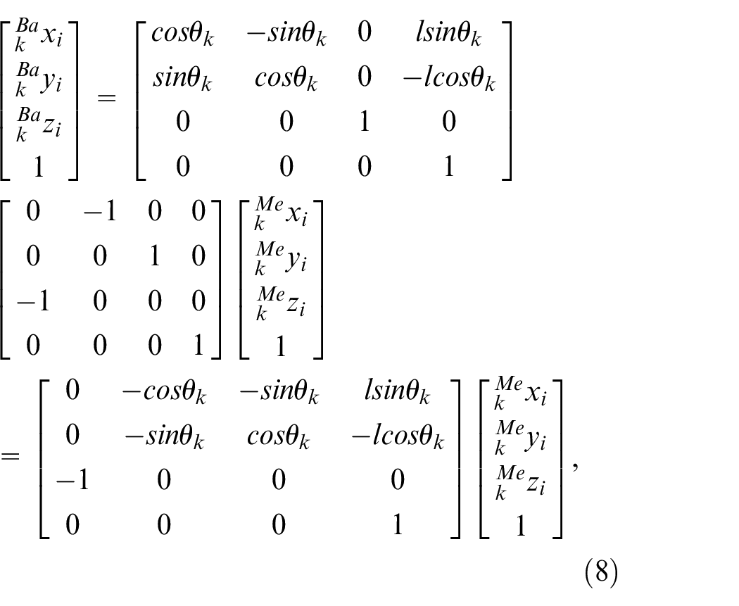
where
Simulation experiments and real measurement
Simulation experiments
Coordinate measuring machine (CMM) is a high-precision inspection method for precision surface,
17
but the metallic sealing ring has an irregular section and an overall annular closed structure, which severely limits the reachability of the probe. Therefore, the 3-D measurement of surface cannot be realized. Due to the lack of 3-D surface measurement methods for metallic sealing ring, the accuracy of the proposed method cannot be directly verified in real measurement, so the dynamic measurement of 3-D surface is simulated. The simulation experiment settings are as follows: (1) The measurement objects are as follows: A standard multi-wave-ring with diameter of 820 mm and section profile within
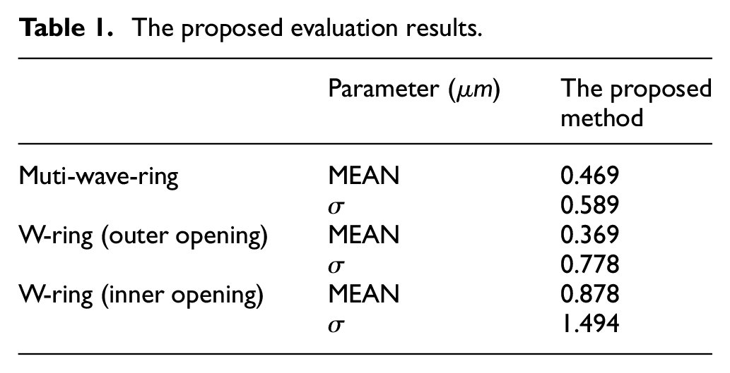
The 3-D point clouds of metallic sealing rings are obtained through the proposed method. Align the point clouds with the corresponding 3-D digital models, and calculate the deviation di of each point in the point clouds. The schematic diagram of the simulation and the deviation chromatogram of the point clouds are shown in the Figure 6. Use the MEAN and

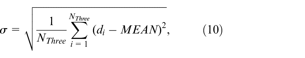
where, Nthree is the point number of 3-D point cloud. The evaluation results are shown in Table 1, the simulation results show that the processing results of the proposed method are very close to the standard measurement results.
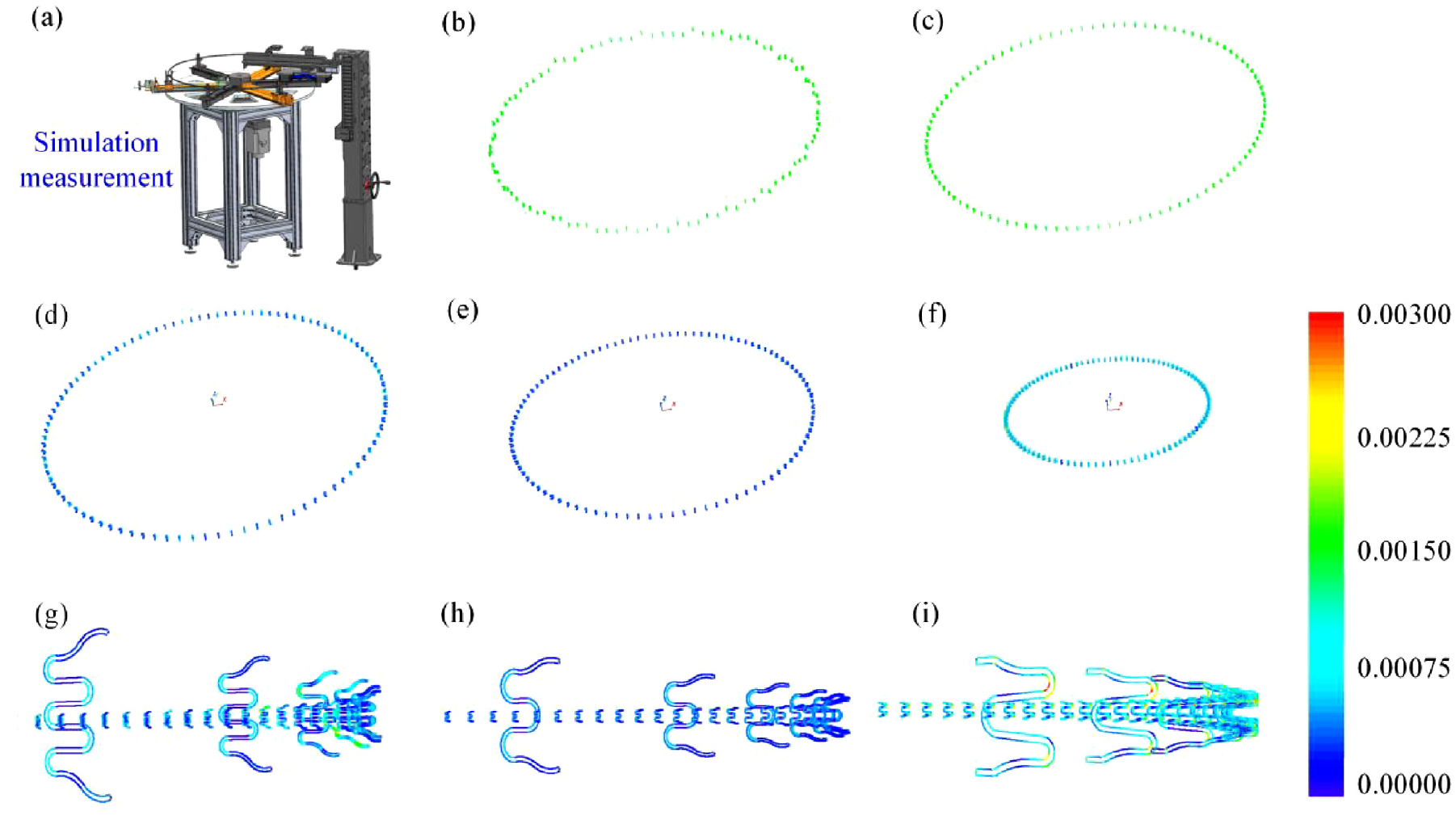
Simulation experiment and results: (a) Simulation measurement. (b) Measurement point cloud under the simulation. (c) Processing result. (d) Processing result of standard multi-wave-ring. (e) Processing result of standard W-ring (outer opening). (f) Processing result of standard W-ring (inner opening). (g) Local amplification of standard multi-wave-ring processing results. (h) Local amplification of standard W-ring (outer opening) and (i) Local amplification of standard W-ring (inner opening).
The proposed evaluation results.
Real measurement
In previous work, 3 the precise measurement of the section profile is achieved. In simulation experiment, the accuracy of the vibration errors compensation method and the 3-D reconstruction of surface method has been fully verified. Therefore, the accuracy of real measurements has also been proven.
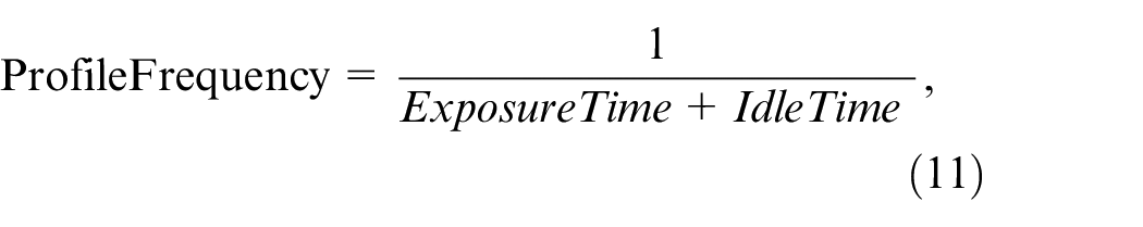
Next, the effect of the proposed method under experimental conditions is shown by real measurements, so as to provide a feasible case for comprehensive monitoring of the forming quality of metallic sealing ring: (1) In order to simulate the rotary motion in the forming process of metallic sealing ring, an on-line inspection test equipment for continuous rolling forming of metallic sealing ring is built, as shown in Figure 7, the equipment can simulate the rotary motion in the forming process of metallic sealing ring with a diameter of 250−850 mm. (2) The real measurement object is a multi-wave-ring with a diameter of 820 mm, it is placed on the test equipment and positioned and clamped by corresponding clamps, the rotation speed of the multi-wave-ring is set to 12 r/min, its section profile is measured by the on-machine measurement system. (3) The on-machine measurement system is equipped with two laser scanners of the same model, the zMe axis resolution is 1.5 μm, the xMe axis resolution is 2048 point/profile, the zMe axis measurement range is 15 mm, and the xMe axis measurement range is 25 mm, the profile frequency, exposure time, and idle time of the laser scanners satisfy the following equation the profile frequency is:
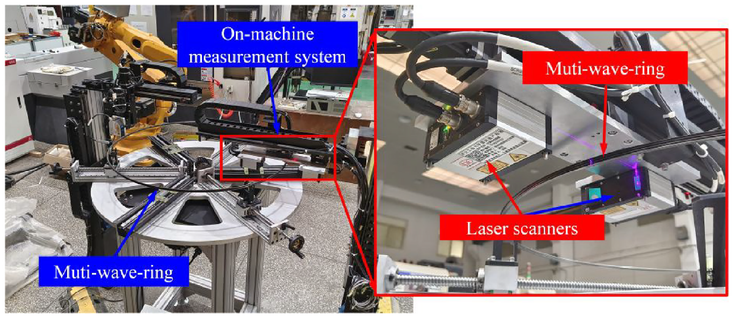
On-line inspection test equipment for continuous rolling forming of metallic sealing ring.
where, the three parameters can be adjusted according to the measurement requirements, and the maximum value of the profile frequency can be set to 1000 Hz theoretically. (4) In the rotation of the metallic sealing ring for one cycle, 10 section profiles are collected (i.e. Profile 0, Profile 1, Profile 2, …, Profile 9). (5) Because the measurement section is irregular, there are serious outliers, missing and noise in the measurement point cloud, therefore, before the vibration errors compensation and 3-D reconstruction of surface, the outliers removal, missing part repair and noise correction are performed.
The 3-D point cloud of the multi-wave-ring is obtained through the proposed method, align the point cloud with the corresponding CAD model, and calculate the deviation di of each point within the point clouds to form a comprehensive monitoring of forming quality. Figure 8 shows the 3-D reconstruction result and forming deviation, the calculation results of the forming deviation are shown in Table 2. In summary, the proposed method realizes the 3-D dynamic measurement of metallic sealing ring forming surface and provides a support for comprehensive monitoring of the forming quality.
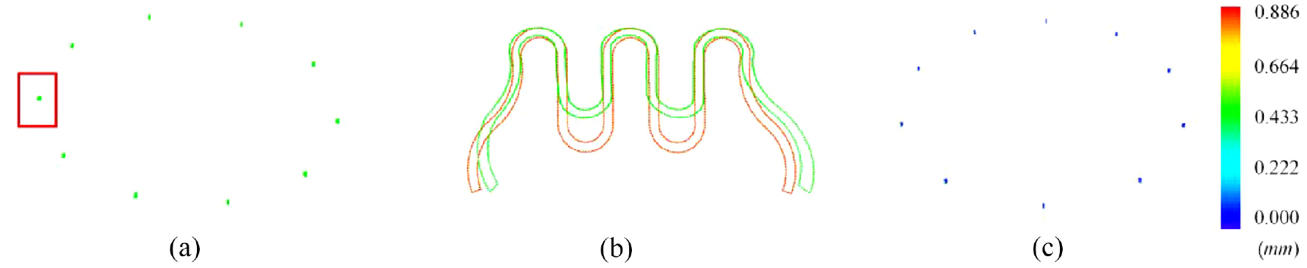
The 3-D reconstruction and forming deviation: (a) 3-D reconstruction. (b) Differences between measurement profile and CAD model point cloud (the green point cloud is the measurement profile, the red point cloud is the CAD model), and (c) Forming deviation.
The forming deviation of the measured object.
Conclusion and future works
In this paper, a 3-D dynamic measurement method for the metallic sealing ring forming surface is proposed. Based on the developed on-machine measurement system, the 3-D dynamic measurement of metallic sealing ring surface during the forming process is achieved, which supports the comprehensive monitoring of the forming quality, and provides a reference for the 3-D dynamic measurement of ring part surface under the rotary motion. Vibration errors compensation and 3-D reconstruction of surface are the main components of this method.
In vibration errors compensation, the medial axis of metallic sealing ring section profile is selected for the self-feature. The medial axis of MPSS is used as the reference for the correct pose of measurement profile, the principle of finding the correct pose of MPRMS is to minimize the distance between the medial axes, which effectively solves the problem of measurement profile transformation caused by random vibration associated with rotary motion. In terms of 3-D reconstruction of surface, a 3-D reconstruction matrix is built based on the rotary motion information of metallic sealing ring and the geometric information of measurement system, and each measurement profile is sequentially transformed to the base coordinate system to realize the 3-D reconstruction of ring part surface. The effectiveness and accuracy of this method have been verified through simulation experiment. Finally, the real measurement is performed, so as to provide a feasible case for comprehensive monitoring of the forming quality of metallic sealing ring, which contributes to lower scrap rates and reduced production costs.
In the future, the research will be carried out on the robustness of the vibration error compensation method to noisy and missing point clouds. In the Section of real measurement, a feasible case is provided. Next, the fast and continuous measurement method of 3-D surfaces and the method for comprehensive assessment of geometric quality based on 3-D surface point cloud will be continued.
Footnotes
Declaration of conflicting interests
The author(s) declared no potential conflicts of interest with respect to the research, authorship, and/or publication of this article.
Funding
The author(s) disclosed receipt of the following financial support for the research, authorship, and/or publication of this article: The work described in this paper was supported by a grant from the National Science and Technology Major Project of China (Project no. J2019-VII-0014-0154).