
Abstract
The mechanism of incremental sheet metal forming is based on plastic and localized deformation of sheet metal. The sheet metal is formed using a hemispherical-head tool in accordance with the path programmed into the computer numerical control milling machine controller. Experimental and numerical analyses have been performed previously on the application of ultrasonic vibration to various metal forming processes. However, thus far, the effects of ultrasonic vibration on incremental sheet metal forming have not been investigated. This article presents the process of design, analysis, manufacture and testing of a vibrating forming tool for the development of ultrasonic vibration–assisted incremental sheet metal forming. The results obtained from modal analysis and natural frequency measurement of the vibrating tool confirmed the emergence of a longitudinal vibration mode and resonance phenomenon in the forming tool. Then, the effect of ultrasonic vibration on incremental sheet metal forming was studied. The obtained experimental results from the straight groove test on Al 1050-O sheet metals showed that ultrasonic vibration led to decrease in the following parameters as compared with conventional incremental sheet metal forming: applied force on forming tool axis, spring-back and surface roughness of formed sample.
Introduction
In recent years, sheet metal-forming industries have been competing with each other to produce products in small volumes, reduce production costs and increase process flexibility. To these ends, conventional sheet metal forming is not economically viable due to the increase in cost and time required to manufacture and set up the equipment, especially for products with complex geometry.
Thus, incremental sheet metal forming (ISMF) was introduced as a method for rapid prototyping and producing products in small volumes.1,2 ISMF is based on localized plastic deformation of a sheet metal using a hemispherical-head tool that follows the path programmed into the controller of a computer numerical control (CNC) milling machine. 3 The method involves two processes: single-point incremental forming (SPIF) and two-point incremental forming (TPIF). 4 In SPIF, no die is used under the sheet metal for support, 5 whereas in TPIF, the sheet metal is supported by a part of a die or a full die.6,7 Many of the existing studies on ISMF have focused on the use of a rigid tool. However, other tools such as laser8,9 and water jet10,11 have been considered as well.
Studying the forming force behaviour in ISMF is one of the most important research subjects.12,13 The increases in the values of input parameters such as vertical step size, tool diameter, wall inclination angle and sheet thickness along with the application of high-strength sheet metals and lightweight alloys (such as AA2024, AZ31B and Ti6Al4V) lead to an increase in the force acting on the forming tool. In addition, improvement of ISMF efficiency by decreasing the spring-back14,15 and surface roughness of the product16,17 is an important challenge in industrializing the process.
Researchers have confirmed the useful effect of ultrasonic (US) energy on the deformation behaviour of metals and alloys.18–35 Thus, it seems that improving ISMF by applying US vibration is essential. No attempts have been made to study the effect of US vibration on ISMF. Therefore, in this study, the authors have focused on applying US vibration to ISMF for investigating the resulting deformation mechanism. Past studies have shown that the application of high-frequency US energy during tension and compression tests of different metals reduces the material’s yield strength under deformation.18–20
Blaha and Langenecker 18 reported the softening phenomenon of materials. This phenomenon is recognized mostly as the ‘Blaha effect’, ‘volume effect’ or ‘acoustoplastic effect’.21–23 It is defined as the reduction of yielding stress during plastic deformation accompanied by a constant strain rate or an increase in strain rate during plastic deformation under constant stress. Their findings show that the changes in mechanical properties under tension accompanied with US excitation are due to the activation of dislocations. This can be ascribed to the fact that the US vibration is preferably absorbed in dislocations, and with their activation, forming forces are reduced. In the beginning, dislocation activation was ascribed to the occurrence of resonance in dislocations. The natural frequency of dislocations is estimated to be about 100 MHz, 24 but the transmission of vibration energy cannot be explained based on dislocation resonance. Another group of researchers 25 found that the activation of dislocations and, consequently, the reduction of forming forces result from the superposition of oscillating and static stresses.
Green 26 conducted various deformation tests on different materials to study the effect of US energy. Consequently, the acoustic softening phenomenon was observed. Then, he concluded that the reduction of yielding strength is proportional to the intensity of the applied US energy.
Many advantages of US vibration application have been reported with respect to metal forming processes such as deep drawing, 27 bending, 28 pipe drawing, 29 wire drawing,30,31 micro-wire drawing,32,33 press forming 34 and tube spinning. 35
Thus, the reduction of variables such as material yielding strength, friction force, forming force, number of processing steps and improvement in the qualitative characteristics of formed samples can be considered part of the useful effects of the application of US vibration to various metal forming processes.
The effects of US vibration on metal forming processes are attributed to two major effects: volume effect and surface effect. The volume effect is related to changes in material properties during deformation, also known as the softening phenomenon. 20 The surface effect is related to changes in the frictional conditions during deformation. 24
In this study, the process of design, analysis, manufacture and testing of the vibrating forming tool was conducted for ISMF for the first time. The main objective of this research was to develop the ultrasonic vibration–assisted incremental sheet metal forming (UVaISMF) process to improve the quantitative and qualitative characteristics of ISMF, such as forming force, spring-back and surface roughness of sample.
Experimental system
UVaISMF equipment
The US equipment used in this research consists of two components: US generator and US vibration transmission system (piezoelectric transducer + tool holder).
To apply US vibration to the forming tool, a King generator with a power output of 1000 W at an operational frequency of 20 kHz was used. The US generator converts low-frequency input voltage (220 VAC, 50–60 Hz) into high-frequency US power (1000 W, 20 kHz).
Experiments were performed using a CNC horizontal milling machine. A Kistler piezoelectric dynamometer was employed for recording the vertical component of the applied force (
US vibration transmission system
The vibration transmission system is combined with the forming tool, so that it can transfer vibration energy efficiently to the sheet. In this study, US energy was applied longitudinally to the forming tool to be vibrated.
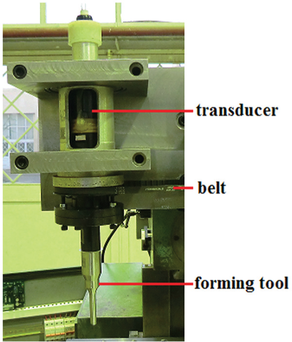
In addition, the vibration transmission system must induce rotational movement of the forming tool. Therefore, a bespoke system was ordered from the manufacturer (Figure 1).
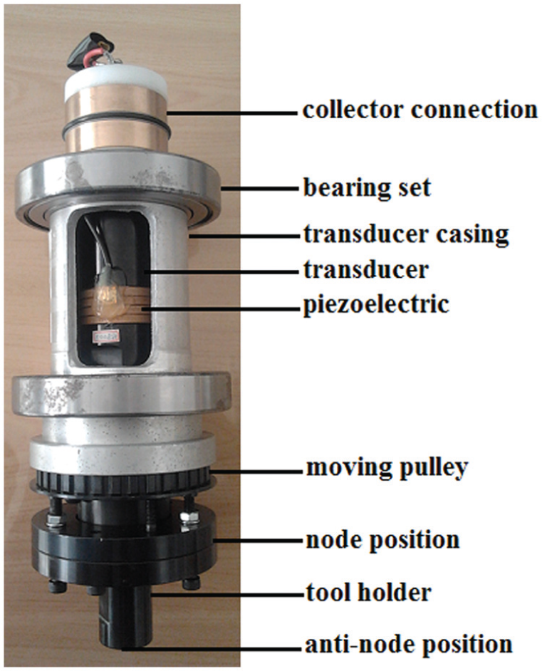
Ultrasonic vibration transmission system.
To set up and run the system on a CNC milling machine, the required fixture was designed and fabricated considering the positions of the spindle (driving part) and bearing set (Figure 2).
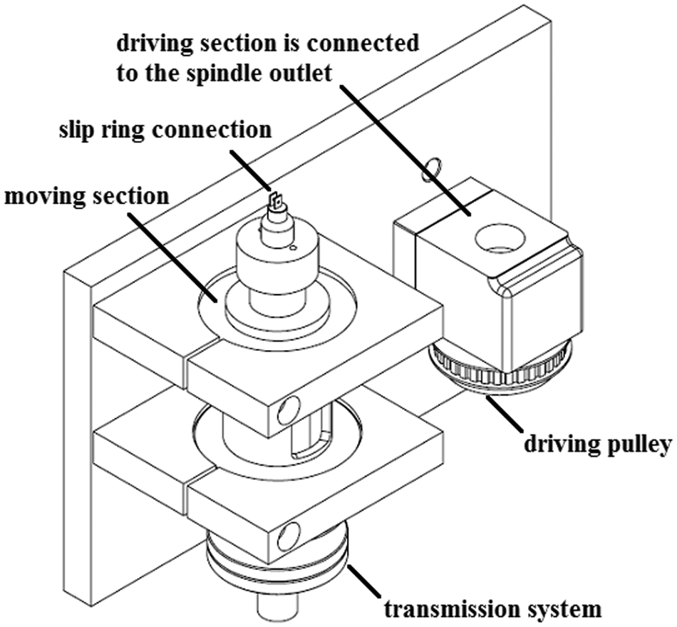
Fixture to set up the system on a CNC milling machine.
System components
According to Figure 1, the system is made of the following components:
Collector connection. In this system, the electrical connection between the generator and the transducer is established by the collector connection. The electrical connection between the system and the generator is static and devoid of rotation. In contrast, the electrical connection of the system with the transducer is of a rotational form. Therefore, this electrical connection should be established properly to avoid failure. To prevent failure resulting from the shortening of brushes or lack of efficiency of the spring part, the authors modified the electrical connection of the system. A ‘slip ring’ containing mercury was used to establish the electrical connection between the generator and transducer. This part acts as a rotary conductor, and there is no circuit disconnection in this state (Figure 3);
Bearing set. The system includes two ball bearings that act as supports, and they are used for positioning the system into the fixture (Figure 2);
Transducer casing. This part is the transducer holder and is pressed into the ball bearings;
Transducer. The transducer transforms electric power into mechanical vibration and transmits this vibration to the tool holder. The tool holder amplitude is reinforced with a concentrator (forming tool);
Moving pulley. This part receives the rotational motion of the driving pulley (spindle) through a belt. In other words, this part imparts rotational motion to the system;
Tool holder. The forming tool is installed on the tool holder.
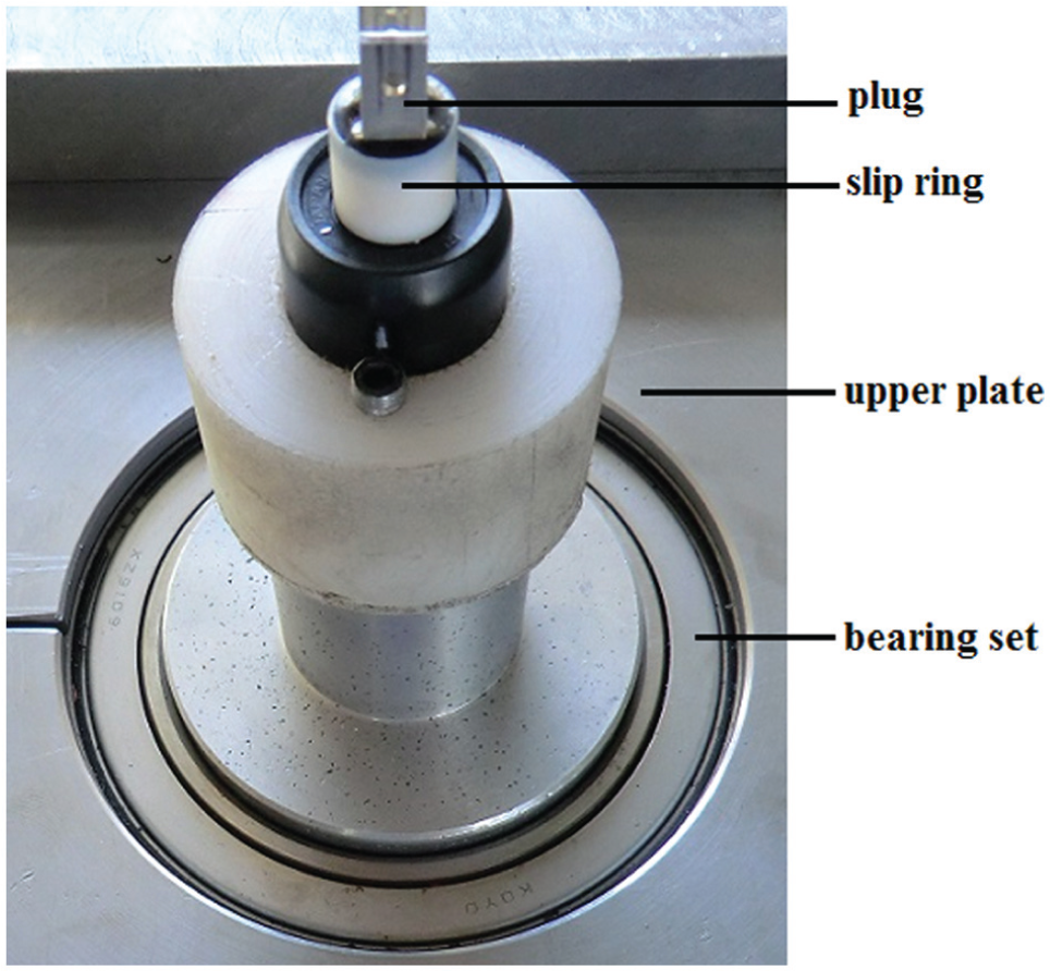
Mounting the slip ring on the system.
In this system, mechanical vibration is transmitted to the tool holder. The front section of the transducer (matching part) and the initial section of the tool holder are connected using two discs. The interface plane defined between two discs is known as the node position. The node position is a point or a plane with zero amplitude. The system is supported on the nodal plane, thus transmitting the maximum possible vibration amplitude to the tool holder. The node position can be adjusted using the connection bolts. Through suitable adjustments to the node position, amplified vibration is generated in the tool holder (anti-node position). The anti-node position (loop) is a point or a plane with non-zero amplitude.
Frequency measurement
The transducer’s resonance frequency was 20.5 kHz according to the manufacturer’s specifications. The equipment necessary for adjusting and confirming this resonance frequency was provided as well. This equipment included a piezodriver, function generator, an oscilloscope and connecting cables (Figure 4). The piezodriver was a piezoelectric actuator. It generated drive waveforms used for controlling piezoelectric transducer. The function generator was used to generate different types of electrical waveforms spanning a wide range of frequencies. The oscilloscope was used to display and analyse the waveforms of electronic signals. It draws a graph of the instantaneous signal voltage as a function of time. This set (frequency measurement equipment) operates as a frequency response function (FRF). Frequency response is the quantitative measure of the output frequency of the transducer in response to the piezodriver.
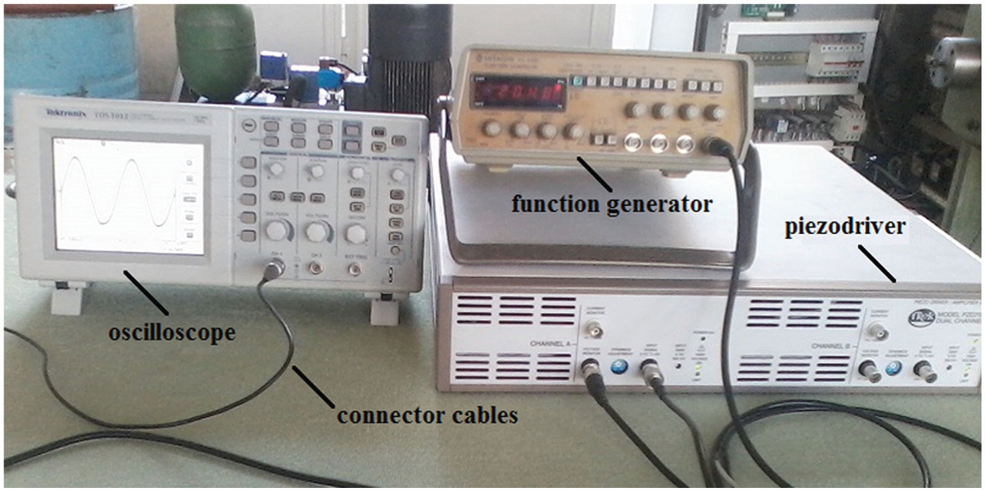
Frequency measurement equipment.
In the simplest terms, a sine wave is injected into the piezoelectric transducer at a given frequency. Then, the transducer responds as a linear structure at the same frequency with a certain magnitude. The frequency value was measured to be to 20.48 kHz, which confirmed the accuracy of the manufacturer-specified transducer frequency (20.5 kHz).
Vibrating forming tool
At this stage, it is necessary to design a hemispherical-head tool capable of reinforcing and transmitting vibration. Therefore, the forming tool is an energy concentrator that performs two functions concurrently:
Execution of the ISMF process;
Transmission and reinforcement of vibration amplitude.
The forming tool was designed and adjusted in the longitudinal vibration mode. For ensuring proper performance of the tool in UVaISMF, it was designed and fabricated based on the principles explained in the following subsections.
Conceptual design
At the outset, it is necessary to determine the geometrical, dimensional and vibrational constraints of the forming tool. The relevant sixfold constraints are as follows:
Base diameter. To set up and assemble the forming tool onto the tool holder, the base diameter of the forming tool should be equal to that of the tool holder (D = 31 mm) to ensure effective and waste-less transmission of vibration energy to the forming tool;
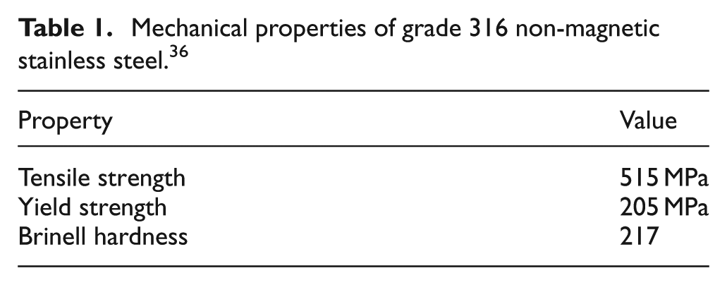
Material. With regard to tool geometry and its application to ISMF, characteristics such as rigidity, resistance against high temperature and machining abilities influenced material selection. High fatigue resistance and low acoustic loss (low absorption of vibration energy) were considered general necessities for a vibrating tool. Therefore, grade 316 non-magnetic stainless steel 36 was selected as the tool material (Table 1);
Natural frequency. The natural frequency of the tool will be in the domain of the generator frequency (20 kHz). Therefore, for establishing vibration (resonance) in the forming tool, its natural frequency was selected to be in agreement with the generator frequency;
Mode shape. The tool vibration was expected to be of the longitudinal mode;
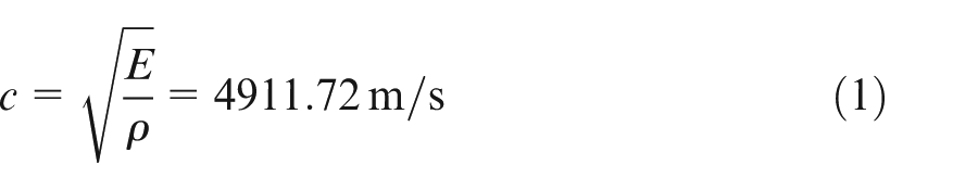
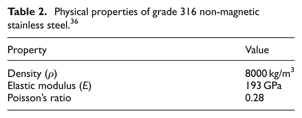
Length. For proper positioning of the vibrating node and anti-node, the tool length was selected to be half the wavelength. Table 2 lists the physical properties of the material. Thus, the propagation speed of the longitudinal elastic wave (
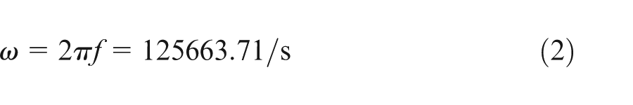
Given that the generator frequency is 20 kHz, the angular frequency (
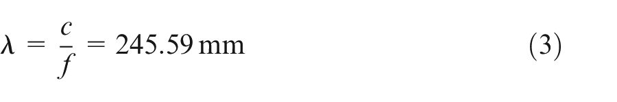
The wavelength (
The important point to consider here is the tuning allowance, which will provide for the inclusion of an additional tool length (of a few millimetres). Thus, after tuning, it is possible to machine the tool and, consequently, adjust the natural frequency of the tool according to constraint (3).
Geometry. With regard to the head shape of the ISMF tool and conventional tool diameters (d = 5, 10, 15, 20 mm), a hemispherical tool nose geometry and a tool diameter of 10 mm were selected. Diverse geometries for concentrator (forming tool) have been suggested, such as stepped, conical, exponential or a combination of them for transmission and reinforcement of vibration amplitude in the deformation zone. 37
Mechanical properties of grade 316 non-magnetic stainless steel. 36
Physical properties of grade 316 non-magnetic stainless steel. 36
For designing the vibrating forming tool, an initial design close to the mentioned constraints was modelled using Abaqus, a finite element method (FEM) software application. 38 Then, preliminary modal analysis was performed in the concerned frequency domain, and vibration specifications of the forming tool such as natural frequency and mode shape were extracted (section ‘Modal analysis’).
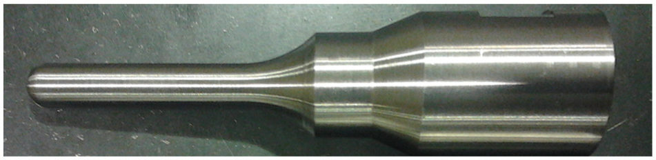
To achieve the ideal resonance frequency of the tool, minor changes to the geometrical and dimensional aspects of the initial design are inevitable. Therefore, through trial and error considering the design constraints, theoretical calculations and software analysis, a forming tool with a hemispherical head having a diameter of 10 mm and a length of 124 mm, as well as a combination of three geometries, namely, stepped, conical and exponential, was finalized (Figure 5).
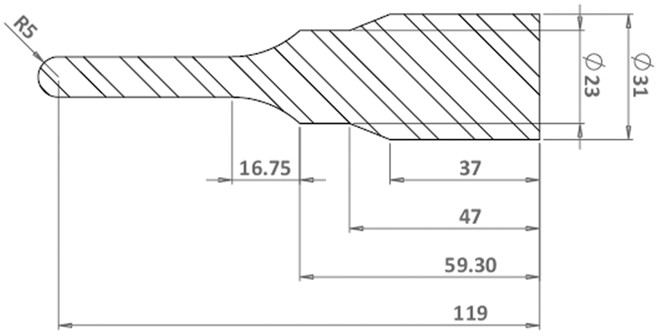
Design of the vibrating tool.
Modal analysis
Natural frequencies and mode shapes are important parameters in the design of a vibrating forming tool for dynamic loading conditions. Modal analysis was used to determine the natural frequencies of tool vibration and mode shapes corresponding to it. Abaqus finite element software, release 6.12, 38 was used to analyse the tool. After tool modelling, the physical and mechanical properties of the material were defined isotropically.
The block Lanczos method was employed in this study to compute the natural frequencies because this method is recommended by Abaqus instructions. 39 No structural constraint was used for modal analysis. For this study, modelling with C3D8R elements was employed for the forming tool. C3D8R has a hexahedral geometry with reduced integration and hourglass control capability. The element has eight nodes with up to six degrees of freedom at each node. The approximate element size was selected to be 1.5 mm. A total of 9728 elements were generated using this model. Figure 6 shows a three-dimensional model of the meshed tool.
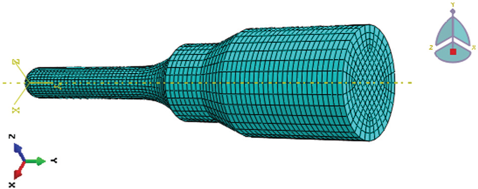
Three-dimensional model of the meshed tool.
Mode shapes are shown in Figure 7. The resonance and anti-resonance frequencies were found to be 20.846 and 21.645 kHz, respectively. It is clear that the bending mode of the forming tool (Figure 7(b)) is undesirable and can nullify the advantages of UVaISMF. In contrast, the longitudinal mode (Figure 7(a)) due to tool vibration with a resonance frequency of 20.846 kHz is the most suitable option for tool vibration.
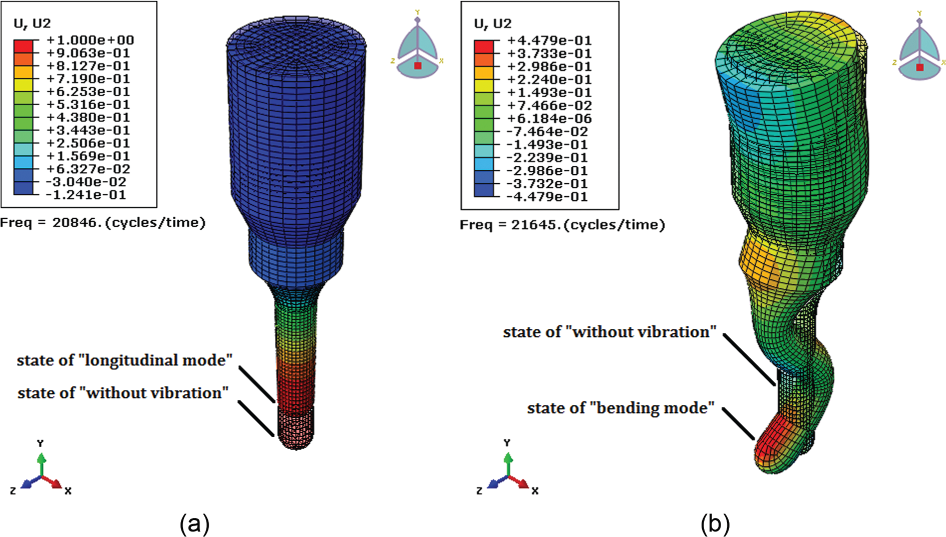
Mode shapes of the tool vibration: (a) longitudinal mode and (b) bending mode.
Vibrational test
The forming tool was fabricated based on the determined specifications (Figure 8). To achieve the maximum vibration amplitude at the tool nose, the connection between the vibration transmission system and the base diameter of the tool was established well by fastening the forming tool onto the tool holder with a bolt and a Mylar washer (Figure 9).
Manufacture of the forming tool.
Mounting the forming tool on the tool holder.
Measurement and adjustment of the tool’s resonance frequency were conducted in two static (without rotation) and dynamic (with rotation) states and in accordance with the method described in section ‘Frequency measurement’. For this purpose, the entire system assembly (transmission system of US vibration + vibrating forming tool) was examined using frequency measurement equipment (Figure 4). Table 3 shows the results of the natural frequency measurement.
Results of the natural frequency measurement.
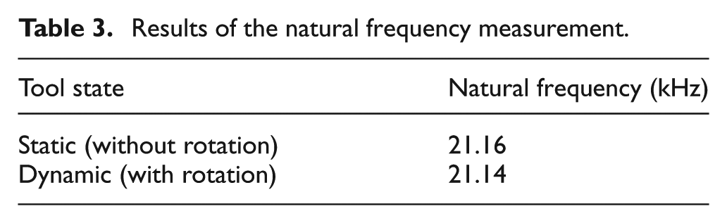
As observed, there is a very small difference between the tool natural frequency in the two static and dynamic states. For proper performance evaluation of the set, one can feel a slippery and frictionless surface in the tool nose upon touching with a finger touch, which confirms the presence of vibration in the tool nose.
The difference between the natural frequency predicted by modal analysis (20.846 kHz) and that obtained using frequency measurement equipment (21.15 kHz) is less than 1.5%. The difference between the generator frequency (20 kHz) and the natural frequency obtained using frequency measurement equipment (21.15 kHz) is less than 6%. Thus, the results obtained from modal analysis and natural frequency measurement of vibrating tool confirmed the emergence of a longitudinal mode of vibration and resonance phenomena under two static and dynamic conditions.
Experimental procedure
Process specifications
The SPIF method of the ISMF process was employed in this study. Figure 10 shows the fixture components.
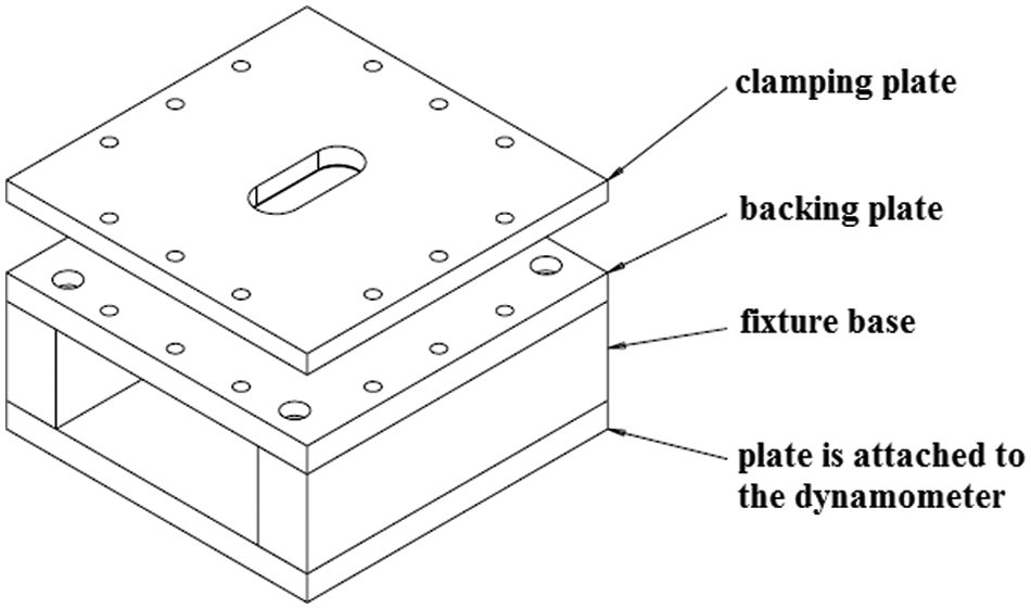
Fixture components of SPIF process.
An Al 1050-O sheet metal (annealed aluminium) was used in the experiments. Since the initial surface roughness of the sheet will influence the results, sheet metals with similar initial surface roughness were selected. Another effective factor was the surface quality of the forming tool, which was smooth and polished. The sheet metal was placed between the clamping and backing plates. Figure 11 shows a schematic diagram of the UVaISMF process.

Schematic diagram of the UVaISMF process.
The sample geometry is in the form of a 50-mm-long straight groove that creates a sequence of vertical and horizontal movements of the vibrating forming tool. The path travelled by the forming tool includes 10 equal penetrations with a vertical step size of 0.5 mm and 10 linear paths (Figure 12). The depth applied on the samples is 5 mm.
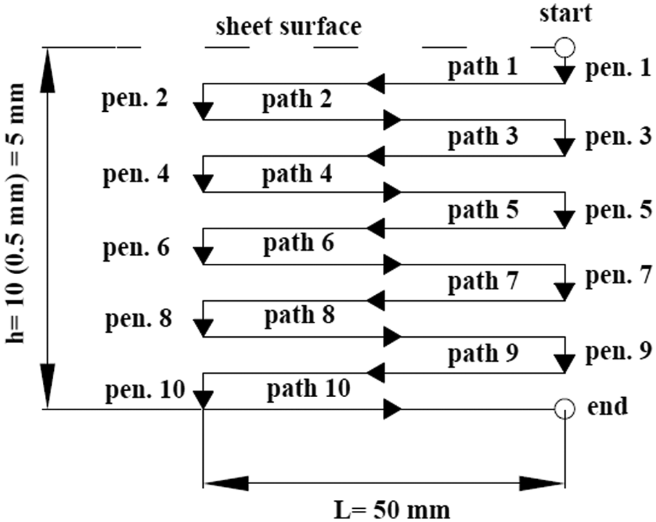
Tool path strategy.
To measure the nose vibration amplitude of the forming tool, a micron digital indicator was employed. The vibration amplitude of the forming tool was measured to be 7.5 µm.
Process parameters
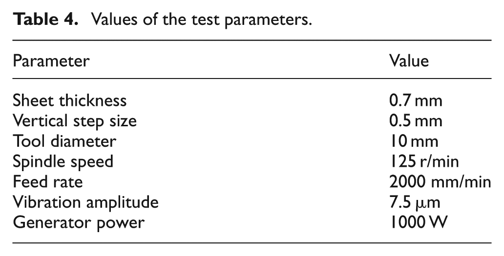
Table 4 shows the values of the test parameters both ‘without’ and ‘with’ application of US vibration.
Values of the test parameters.
Process execution
To exclude the effect of lubricant on the output results and prevent the interference of its effect with the effect of vibration application, the tests were conducted in the absence of lubricant. Figure 13 shows the formed samples both ‘without the application of vibration’ (without US) and ‘with the application of vibration’ (with US).
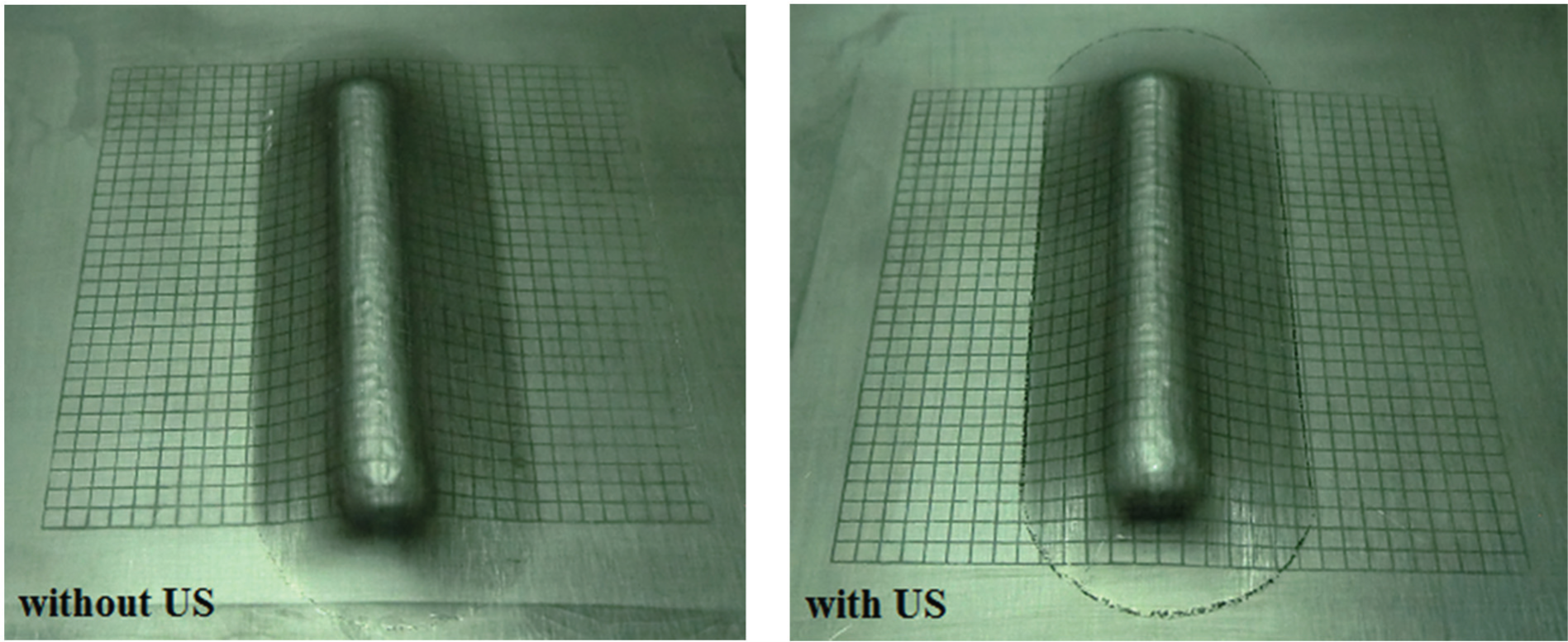
Formed samples in the straight groove test.
Results and discussion
Effect of US vibration on vertical component of forming force
The vertical component of forming force measured by the dynamometer is denoted by
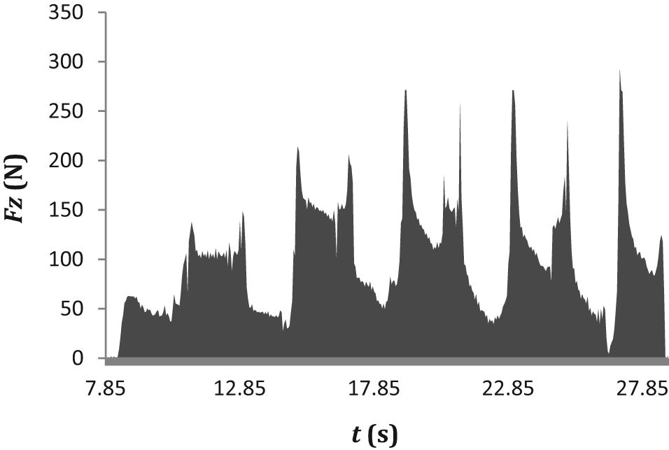
Behaviour of
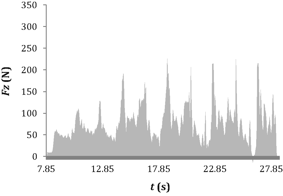
Behaviour of
Figure 16 shows a combination of Figures 14 and 15. The elliptical borders (in red colour) show the tool penetration positions. In these positions, the forming tool penetrates into the sheet metal vertically (0.5 mm). Hence, the peaks in Figure 16 arise from the vertical penetration of the tool into the sheet. Between successive peaks, the forming tool forms the straight path of the groove.
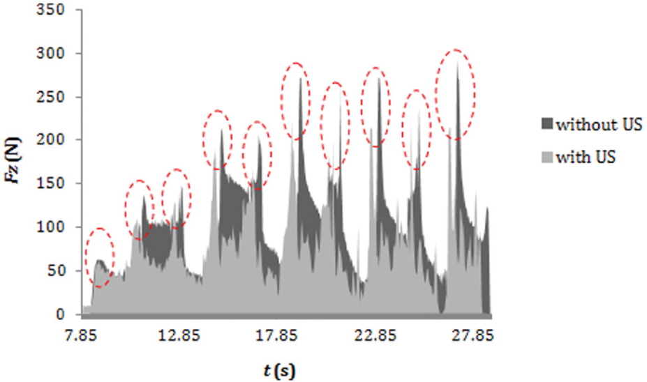
Positions of the penetration stages.
To analyse the measured results more accurately, the two situations of ‘without’ and ‘with’ the application of vibration were compared separately in the two stages, namely, vertical movement (penetration) and horizontal movement (path).
Figure 17 shows a comparative diagram of
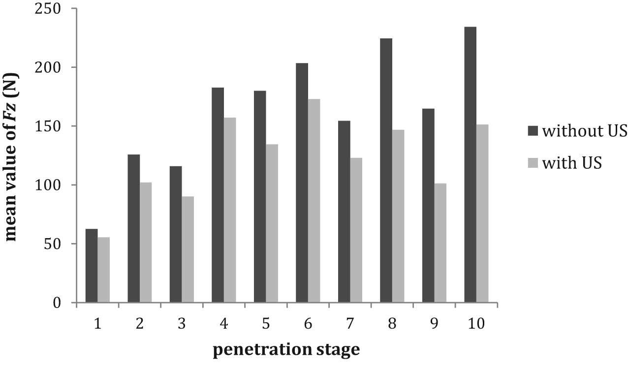
Comparative diagram of
Figure 18 shows a comparative diagram of
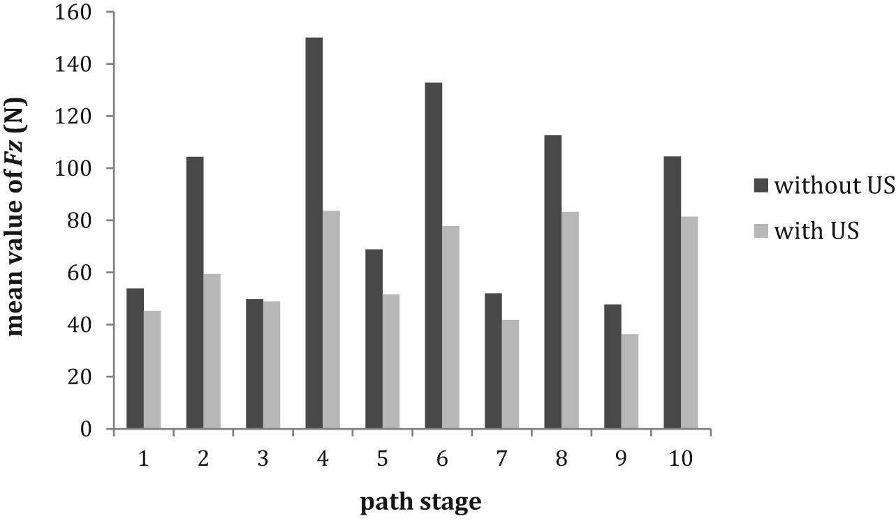
Comparative diagram of
Based on the experimental results, some of the effective factors in terms of force reduction in UVaISMF are as follows: frictional changes between forming tool and sheet metal, surface elastic–plastic deformation, dynamic effects of US vibration and changes in material flow. Generally, all of these factors are associated with the surface effects of US vibration.
Consequently, reduction in the vertical component of the forming force was mainly due to surface effects, or changes in tool–sheet contact conditions, and not due to volume effects.
Effect of US vibration on spring-back
The depth of the formed samples was measured using a contourograph at five points with an inter-point distance of 10 mm. The average of these measurements was registered as the formed depth after unclamping the sheet metal (
Results of the formed depth measurement.
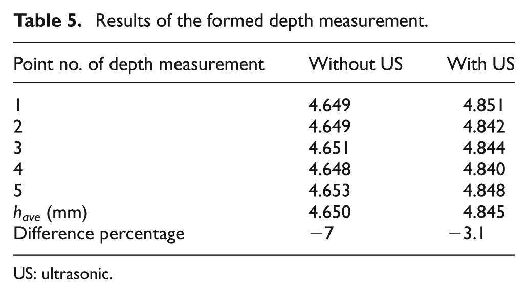
US: ultrasonic.
For evaluation of spring-back, a criterion called the ‘coefficient of spring-back’ determined by the following relationship was used 40

In the above expression,
Table 6 lists the spring-back coefficients of the formed samples. As can be inferred, the depth increased and the spring-back coefficient decreased when employing the vibrating tool in comparison with that when employing the non-vibrating tool.
Spring-back coefficients of the formed samples.
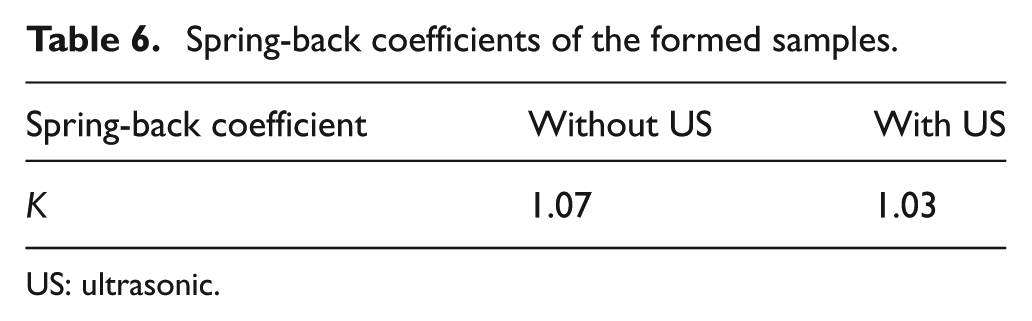
US: ultrasonic.
It seems that the surface elastic–plastic deformation due to US effects increases the temperature at the tool–sheet interface. An increase in temperature affects material flow. Therefore, the vertical component of forming force and the spring-back coefficient decreased.
Effect of US vibration on surface roughness
To measure and compare surface roughness of the formed samples, three parameters
The back surfaces of the samples were measured using a MarSurf PS1 Mahr profilometer. The plunger of this profilometer was made to travel in the direction of the formed groove. The measurements were conducted within the middle region of the samples. The middle region is at an adequate distance from both ends of the samples. Table 7 lists the measured values of the surface roughness parameters.
Measured values of the surface roughness parameters.
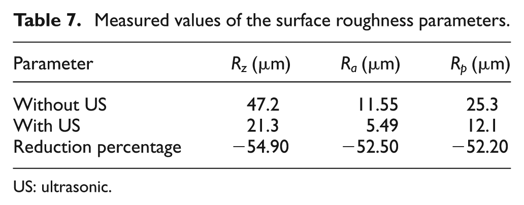
US: ultrasonic.
Figure 19 shows a comparative diagram of the surface roughness parameters ‘without’ and ‘with’ the application of vibration. As can be observed, the application of vibration to the forming tool led to decreased surface roughness.
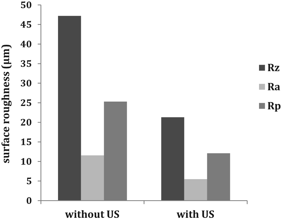
Comparative diagram of the surface roughness parameters.
Applying US vibration to the forming tool causes an alternating motion at the tool–sheet interface in the local deformation zone, which leads to the following results:
Static friction was changed to dynamic friction between the forming tool and the sheet metal surfaces, which finally reduced slippery–sticking behaviour. Thus, material flow and surface quality of the sample improved;
The alternating motion led to elastic–plastic deformation of surface asperities, as the hills have a greater tendency to move into the valleys. Therefore, surface quality of the sample improved.
Conclusion
In this article, the process of design, analysis, fabrication and testing of a vibrating forming tool for development of UVaISMF was presented. Accordingly, to test the performance of the developed vibrating tool, a straight groove test was conducted on Al 1050-O sheet metals both ‘with’ and ‘without’ the application of vibration. The important results of this research are summarized as follows:
The emergence of resonance in the longitudinal mode of the vibrating tool was confirmed in static (without rotation) and dynamic (with rotation) states based on the results of the numerical analysis (f = 20.846 kHz) and measurement of the tool’s natural frequency (f = 21.15 kHz). Thus, the vibrational performance of the tool in terms of its installation on the vibration transmission system and execution of UVaISMF was proved;
The results of the modal analysis show that the FEM package Abaqus can be used successfully as a powerful and reliable instrument predicting the vibrational behaviour of a vibrating forming tool;
The comparison between the behaviours of
The comparison between the average values of the formed depths ‘without’ (
The comparison between the spring-back coefficients of the formed samples ‘without’ (K = 1.07) and ‘with’ the application of vibration (K = 1.03) showed that the spring-back rate decreased under the US vibration effect;
The comparison between the values of surface roughness parameters achieved ‘without’ and ‘with’ the application of vibration showed that the values of
Footnotes
Appendix
Acknowledgements
The corresponding author gratefully acknowledges the support provided by Dr M. A. Rasoli and Dr A. Abdullah for technical assistance. He also takes the opportunity to appreciate friendly assistance of Mr Karimnejad and Mr Hosseinpour for providing machineries.
Declaration of conflicting interests
The author(s) declared no potential conflicts of interest with respect to the research, authorship, and/or publication of this article.
Funding
The author(s) received no financial support for the research, authorship, and/or publication of this article.