
Abstract
Tokamak is an important device for controlled nuclear fusion research. The plasma electronic density control system (PEDCS) is an important system for controlling the Tokamak discharge process, which should be of high stability, rapidity, and accuracy. Gas seeding systems are widely used in many Tokamak devices to achieve plasma electronic density control. According to the mechanism model analysis for the plasma electronic density object, an adapted single neuron proportion integration differentiation (PID) control algorithm with the radial basis function (RBF) neural network tuning is studied. The principle and the implementation of the intelligent control algorithm are described in detail in this paper. The intelligent controller enables the system to optimize the PID parameters online according to the density state in the discharge process. The experimental results show that the adapted algorithm achieves a good control effect and also improves the control performance. The proposed method provides a useful reference for Tokamak devices and other similar control systems.
Keywords
Introduction
The Tokamak is an important device for controlled nuclear fusion research. 1 Plasma electronic density is an essential parameter in studying plasma characteristics in Tokamak experiments, which is required to be stable to meet the experiment’s demand.2,3 How to achieve the effective control of plasma density under various experimental conditions and meet the requirements of experiments for stable and reliable plasma density is an important issue to be solved in Tokamak experimental devices. Accurate and effective control of plasma density in the Tokamak device is essential.
Many factors are affecting the plasma electronic density, such as gas seeding during the discharge process, the ionization rate and the purity of the working gas, the gas recycling rate of the vacuum conditions, and the vacuum degree of the chamber, etc.4–7 In general, the change in the total amount of gas can be controlled by manual gas seeding. The difference in ionization rate is also predictable, but the law of its change is not clear. The discharge breakdown voltage can be controlled to an appropriate value to minimize the difference in ionization rate so that the effect on plasma density is negligible. In the case of other factors, they are uncontrollable. There are many Tokamak devices, such as ASDEX-Upgrade, 8 KSTAR, 9 Tore Supra, 10 HT-7, 11 and EAST, 12 etc., achieving plasma density control with a gas seeding system using a piezo crystal valve, a projectile emitter, or supersonic molecular beam injection (SMBI).13,14 Because of the above-mentioned factors that affect the plasma electronic density, it is difficult to establish an accurate plasma electronic density control model, so it is difficult to achieve an accurate model-based control algorithm. At present, the plasma electronic density control system (PEDCS) of most Tokamak devices adopts a proportion integration differentiation (PID) control algorithm.15,16 The conventional PID algorithm has the properties of simple structure, flexibility, and reliability. The control mode is that the parameters of PID are set by experiment operators before each discharge. During the discharge, these parameters and other related elements are used to calculate and give the control signal. It has the advantages of a simple structure and easy adjustment of parameters. However, it is difficult to complete the control process for complex models with uncertain coupling and parameters. In the actual use process, it is necessary to rely on certain experiences and a large amount of experimental data to obtain the set parameters. Due to too many affecting factors, any set of fixed PID parameters can hardly satisfy the optimal control in the discharge process of the device. Therefore, the real-time, accuracy and effectiveness of the control algorithm in the PDCS need to be further optimized. Some improved PID algorithms have been well applied in many applications.17,18 In recent years, to avoid difficulties related to the control model, a recent methodology, model-free control, is developed and widely used.19,20 In this method, the control system is represented by an ultra-local low-order (mostly, first or second-order) differential equation, therefore, this approach with input-output data-driven does not need a large-scale precise mathematical model. This control strategy allows the synthesis of a simple PID controller type, which has already been successfully applied in many fields, such as power electronics control systems, 21 and vehicle control. 22 With the application of nonlinear and complex control objects in practice, the control methods based on the system model are difficult to solve the various uncertain factors and environmental disturbances. Some nonlinear feedback controller designs for time-delay uncertain systems are developed.23,24 The biggest feature of intelligent control is the ability to cope with complex and varied systems’ internal and external changes with good self-learning and self-adaptive capabilities. With the wide study of various intelligent control algorithms, it is the right time to design and establish an intelligent control algorithm for Tokamak devices.
Gas seeding systems are widely used in many Tokamak devices to achieve plasma density control. This paper first introduces the design of the PEDCS with a gas seeding system using a piezo crystal valve. At present, the neural network control, genetic algorithm control, immune regulation control, etc., which have been applied in the field of intelligent control, fully verify the various information recognition and processing mechanisms existing in the human body system from the perspective of human biology. They are conceptualized, theorized, and modeled, and then the appropriate intelligent control algorithm is proposed. For example, neural network control is based on the characteristics of adaptive and distributed information transmission processing of brain neural tissue. By analyzing the mechanism model of the plasma density object, an intelligent controller based on a single neuron PID with the radial basis function (RBF) neural network is designed and applied. In this work, the principle and the implementation of the intelligent control algorithm are described in detail. The intelligent controller enables the system to optimize the PID parameters online in real time according to the density state in the discharge process. The experimental results show that the proposed algorithm achieves a good control effect and improves the performance of the control system.
The rest of this paper mainly includes the following sections. Section II introduces the principle and system structure of the PEDCS. According to the requirements and the indicators of the control system, the proposed control algorithm based on the single neuron PID is presented in detail in Section III. The experimental results are given and discussions are performed in Section IV. Section V is a summary of the paper.
Structure of the PEDCS
Principle of gas seeding
During the discharge of the Tokamak device, the amount of variation of working gas particles in plasma could be expressed by equation (1):
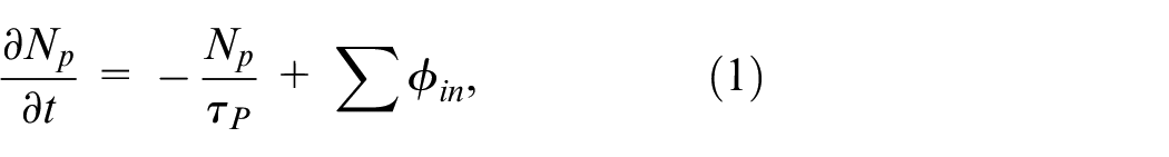
where τp is the particle confinement time. Σφin is the various particle sources. Np is the number of working gas particles, which generally depends on the working gas injected outside the plasma chamber and the recirculating working particle flow on the plasma wall and the pore barrier. Equation (1) can be simply written as:
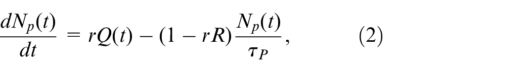
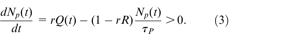
where r is the feeding efficiency. R is the recycling coefficient between the gas wall and the column. Seen from the above equations (1) and (2), according to the plasma particle confinement time and the recirculation coefficient, it is beneficial to control plasma density by injecting an appropriate amount of working gas at the right time during the plasma discharge. 19
To obtain a high slope of density rise in the plasma ramp-up phase, equation (2) should be satisfied with the following equation:
As seen from equation (3), if the working particle recirculation rate is less than the working particle decay rate, external working gas injection is required. The amount of injected gas is determined by the recycle factor and the density of the initial plasma.
To keep the plasma density unchanged at the flat top of the plasma current, equation (2) should be satisfied with equation (4):
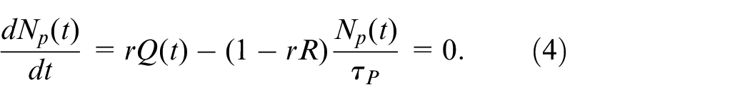
If the working particle recycling coefficient can maintain the plasma density, that is to say, that rR > 1, there is no need to inject gas at this time. If the recycling coefficient of the working particles is small (rR < 1), it is necessary to supply the working gas by injection, and the injection amount of working gas can be estimated by equation (5):
where Np (0) is the initial number of working gas at the beginning of external gas injection. Therefore the amount of gas injection is:
Those formulas are all the results under ideal conditions. These formulas are the basis for the design of the control system and should be appropriately corrected according to the actual situation in the experiment.
Control system structure
Gas seeding systems are widely used in many Tokamak devices to achieve plasma density control. This paper first presents the design of the PEDCS with a gas seeding system using a piezo crystal valve. The PEDCS mainly consists of three units: the density measurement subsystem, the feedback control subsystem, and the gas seeding subsystem. The schematic diagram of the density feedback control system is shown in Figure 1. The real-time density feedback control system of this design mainly adopts the control form based on the lower-upper machine with Windows & Linux operating systems. An industrial computer on-site is used as the lower machine, which runs the Linux operating system, and a Windows upper machine is located in the main control hall to perform the operator’s preset of the density waveform and transmit the data of the lower machine, etc. The first step is to set various preset parameters on the operating interface of the upper machine and transmit them to the lower machine through the network. The lower machine accepts the parameter trigger signal sent by the master control system, and then the master control system sends the acquisition trigger signal again. After the control system of the lower machine receives the acquisition command, it starts acquisition and processing and sends control signals. At the same time, it transmits collected signals to the Upper machine and processes information such as signal waveforms.
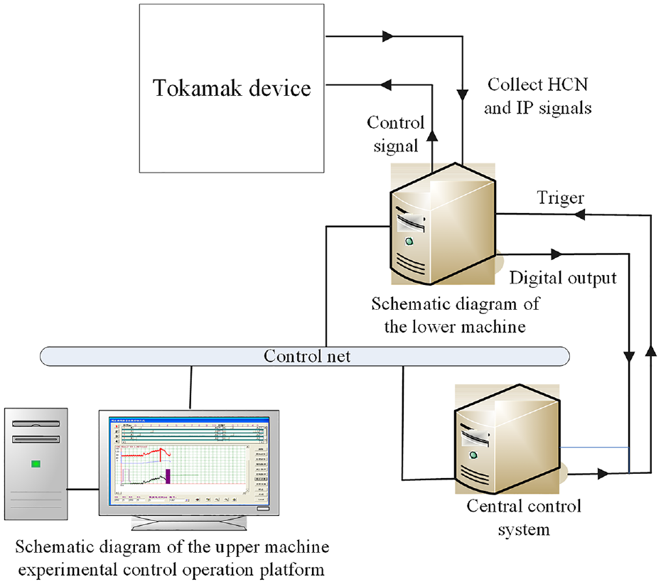
Schematic diagram of the density feedback control system.
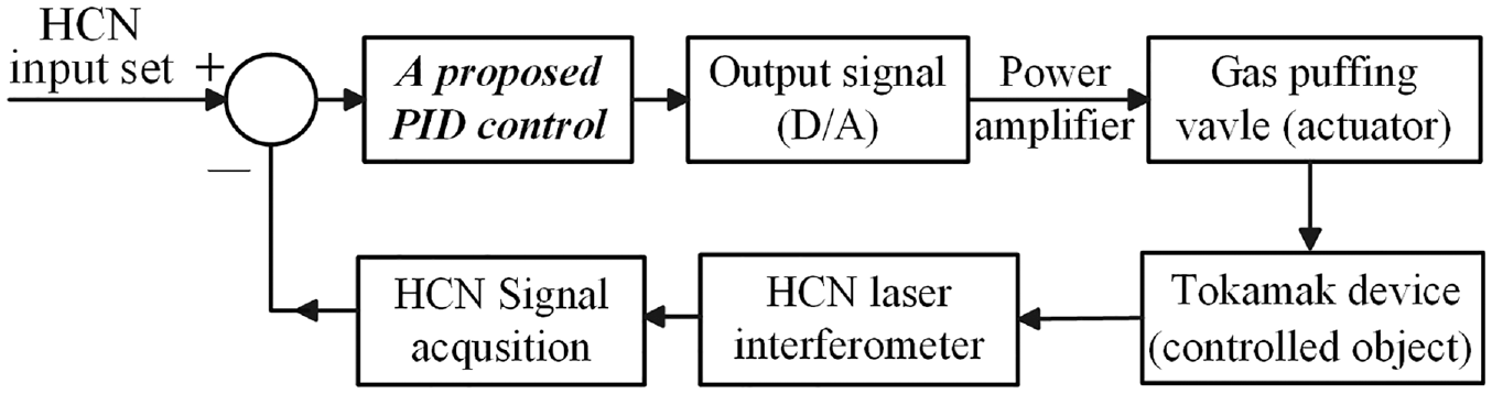
The detailed system structure is shown in Figure 2. As for the measurement subsystem, an HCN laser interferometer is employed for measuring the plasma electronic density, 25 and the signal is put into the signal processing circuit for getting a suitable voltage for analog-to-digital (A/D) acquisition. The far-infrared laser is used as the emission source and measurement signal, which greatly overcomes the problem that the electromagnetic wave has a long wavelength and can only measure lower-density plasma.
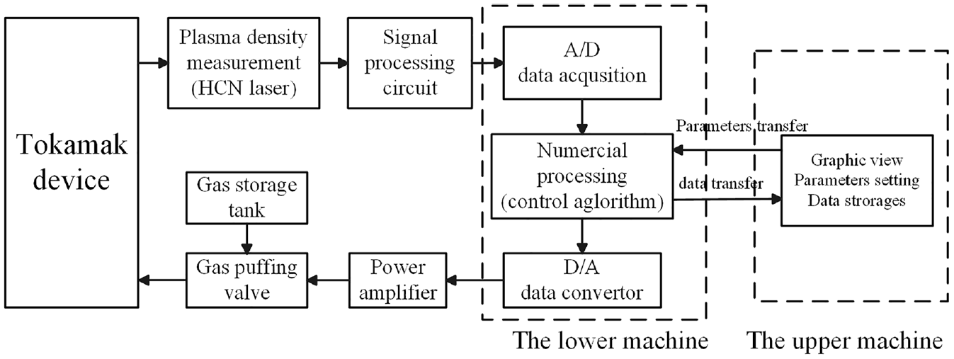
Structure of the PEDCS in the Tokamak device.
In the feedback control subsystem, a control signal is given from the analog-to-digital (D/A) port of the acquisition card through a certain control cycle after certain processing and operation on the collected original signal. The feedback control subsystem is a quasi-real-time computer control system with the structure of the upper machine and lower machine. The structural design of the upper and lower position machine fully exploits the advantages of the two operating systems, effectively improving the performance and control effect of the PEDCS. The upper computer located in the main control hall adopts the Windows operating system and has good human-computer interaction. It mainly realizes the functions of obtaining the shot number, parameter setting, data storage, data display, and communication with the lower computer. The lower computer at the control site adopts the Linux operating system. It has strong running stability and mainly realizes data acquisition, feedback control, and communication with the lower machine. As the core component of the whole feedback control system, the lower machine system includes the data acquisition module used as the detection link, the data processing module used as the controller, and the control output module employed as the actuator. These modules constitute the feedback control subsystem and also determine the stability, real-time, and robustness of the system.
Normally, the Tokamak gas seeding subsystem controls the flow of working gas into the Tokamak by selecting the closing and opening of the PEV-1 piezo crystal valve. 26 Based on experimental measurements, when the voltage affected by the PEV-1 piezo crystal valve is in the range of 50–100 V, the control of the amount of gas supplied is linear with the amplitude of the applied voltage. At the same time, the air intake also has a linear relationship with the time of voltage action.
At present, in most Tokamak devices, the PID controller is mostly used, which is designed to control the amount of seeding by the difference between the pre-set HCN signal and the actual measured value. The PID control mainly controls the controlled object by linearly combining the proportional, integral, and differential deviation between the pre-set value and the real value of the controlled object. This conventional PID algorithm is of simple structure, flexibility, and reliability. However, fixed PID parameter values are hard to meet the changeable control in the different processes of device discharge. This work mainly studies the adapted control algorithm of the PEDCS, which is shown in Figure 3. This work also gives a proposed PID control algorithm design.
Schematic of the feedback control system.
An intelligent solution is proposed to improve the controller performance and the superiority of the intelligent controller performance is verified by simulations and experiments. The PEDCS is achieved by controlling the closing and opening of the PEV-1 valve, including the time of closing or opening, or the applied voltage amplitude. The proposed PID control algorithm is described in detail in the following section.
An improved single neuron PID controller design
Density control system structure
When the traditional PID controller controls the plasma density, the key parameters including proportional, integral, and differential coefficients often need to be pre-set and continuously adjusted according to the experimental data, so the controlled object cannot be tracked in real-time accurately in most cases.27,28 Due to the self-adapting ability and self-learning ability of the neuron network algorithm, it is possible to design an intelligent controller combined with a PID controller.29,30 In this way, the PID parameters can be adjusted online in real time accordingly for achieving strong robustness and good adaptability of the control system. The process of the plasma control system and the proposed PID controller system is shown schematically in Figure 4.
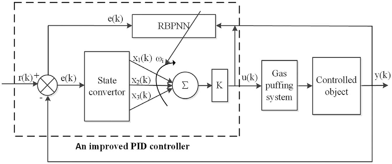
Structural diagram of the plasma control system (the diagram of the adapted PID controller inside the dotted box).
As shown in Figure 4, r(k) is the pre-set value of the system. The definition of error e(k) = r(k)−y(k) is the difference between the real output value and the expected value. Meanwhile, e(k) is also the input of the state convertor. Traditionally, the single neuron PID has the following parameters. xi, ωi (i = 1,2,3, …) are the inputs of the controller and the connection weight coefficients, respectively. K is a neuron proportionality coefficient. There are three input signals in a single neuron PID-controlled neural network, x1(k), x2(k), and x3(k), and they were defined as:
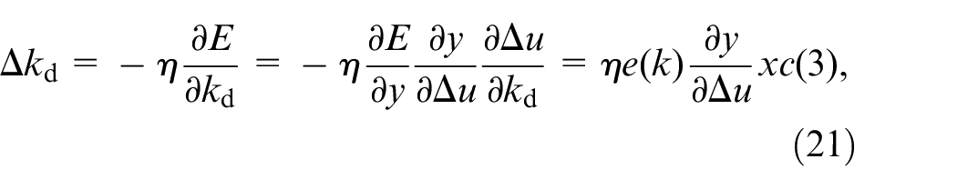
Using an incremental control algorithm, the control algorithm can be expressed as equation (8):
Through the above calculation, u(k) can be obtained, which is u(k) = u(k−1)+△u(k). The proposed neuron control algorithm has a good adaptive adjustment ability, that is to say, the algorithm structure adapts to the disturbance change of the control system through continuous learning.
Adjustment of RBF network parameters
Principle of the RBF neural network model
In the late 1980s, Moody and Darken Radial proposed a special neural network named basis function (RBF) neural network,31,32 which has a three-layer forward neural network. This RBF neural network has a single hidden layer with a linear mapping relationship from hidden layer space to output space linear. But the mapping from the first input layer to the output layer is nonlinear. This structure greatly accelerates the speed of learning and avoids the local minimization problem. The RBF neural network structure is shown in Figure 5.
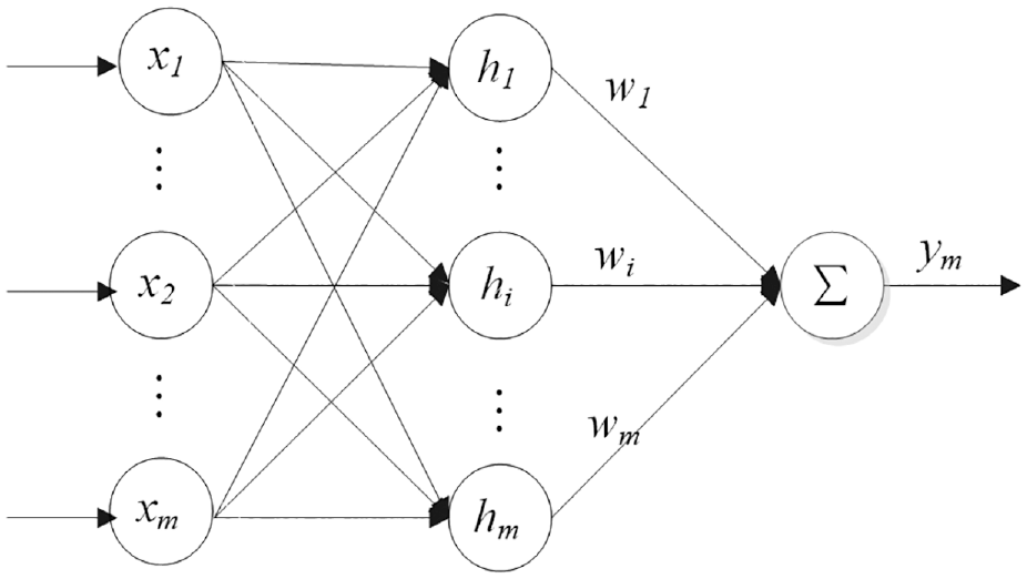
Structure diagram of the RBFNN.
In the RBFNN structure, the input data vector of the network is X = [x1, x2, …, xm ] T , where m is the number of inputs. The radial basis function vector of the RBFNN is assumed h = [h1, h2, …, hm ] T , where hj is calculated by the Gaussian basis function:
where cj is the center data vector of the j-th node of the network and it can be expressed as cj=[cj1, cj2, … cji…, cjm] T , i = 1, 2, …, n. Assured the base width data vector of the network is B=[b1, b2, …, bm] T , bj is the base width of the j-th node with the value of being greater than zero. The weight data vector of the network is W=[w1, w2, …, wm] T , and then the output of the identified network is calculated ym(k) = w1h1+w2h2+… + wmhm. Here, we set the performance index function is
Based on the gradient descent method, the iterative algorithms of the output weight, the node center, and the node base width parameters are as follows:

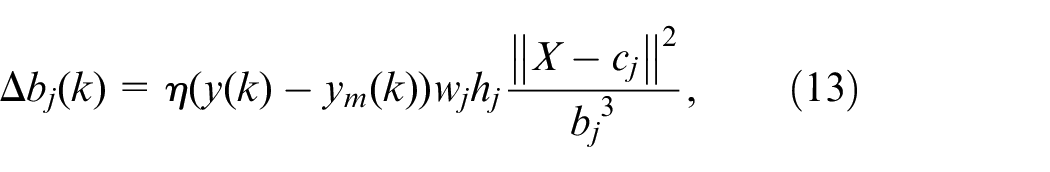
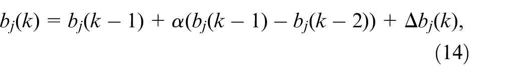
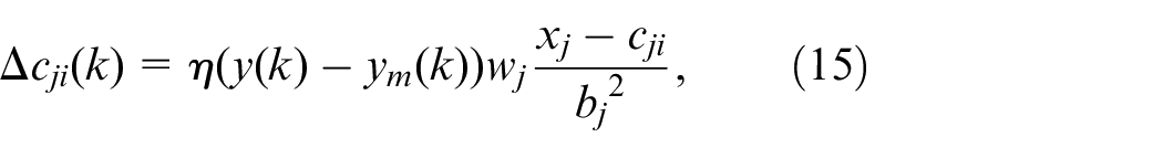
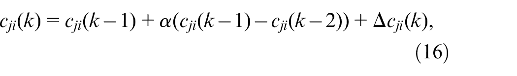
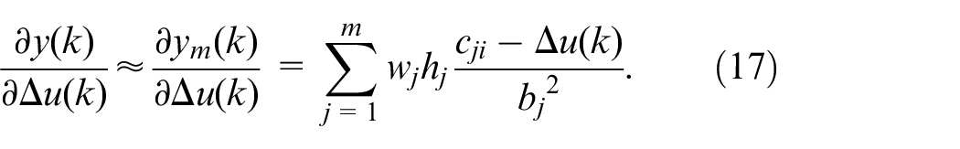
where η is the network learning rate and α is the momentum factor. The calculation method of the Jacobian matrix (the sensitivity index for the object output to the change of the control input) is as follows:
PID parameter tuning based on the RBFNN
The tuning performance of the RBF neural network is set to:
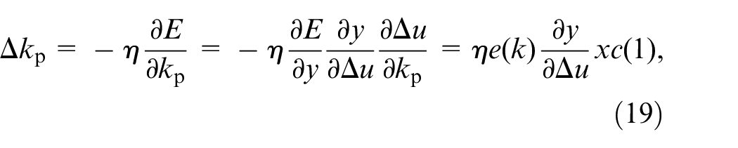
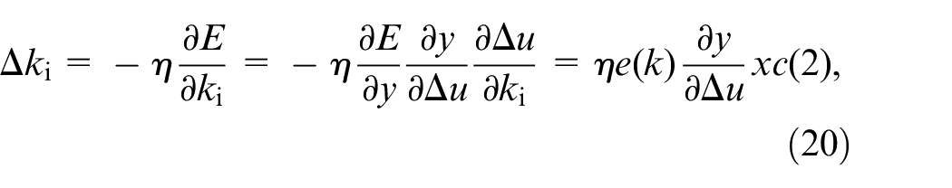
And then the gradient descent method is applied to adjust kp, ki, and kd. Finally, we can get:
where
According to the above algorithm, this single neuron control part is still a PID algorithm. However, the weights of the single neuron network can be adjusted online, which has a strong ability of self-adaptive and self-learning and can adapt to environmental changes or the model uncertainties and then enhance the robustness of the system.
K adjustment
The adjustment of the proportional coefficient K controller is performed in the proposed PID controller. The adjustment algorithm adjusts the proportional coefficient K(k) according to the change of the input error e(k). The adjustment factor adopts the general rule of hormone secretion.
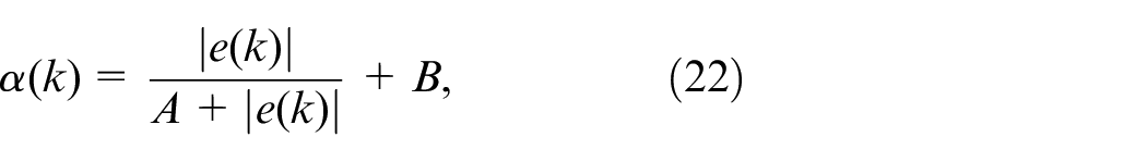
where k is the k-th sample time, α(k) is the adjustment factor, and e(k) is the difference between the real output value and the expected value. A and B are the parameters for the controller adjustment. In practice, A and B can be set to 1 and 0.5 respectively, which can be adjusted according to the actual situation. Therefore, the adjustment strategy for K is

where K(k) and K(k−1) are the proportional coefficients.
Experimental results and discussions
Approximate mathematical model of the control system
In Tokamak experiments, conventional model identification methods such as impulse response and step response are not allowed to obtain the plasma density object model. Therefore, this paper combines experiments and uses the physical principles of plasma density to carry out mechanism modeling to determine the object model. According to the above described in Section 2.1, the equation for the change of the plasma electronic density in the Tokamak device is:
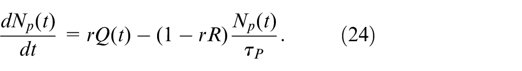
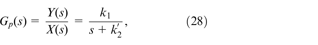
In the Tokamak density control system, Np is the total number of working gas particles, which can be considered as the density output y(t) in the controlled Tokamak device (that is the controlled object). The input Q(t) is considered as the input number of working gas particles of the controlled object x(t). The coefficients r and −(1−(rR)/τp can be substituted by coefficients k1 and k2 respectively. X(s) and Y(s) are Laplace transforms of x(t) and y(t), respectively. Then equation (24) can be expressed simply as:
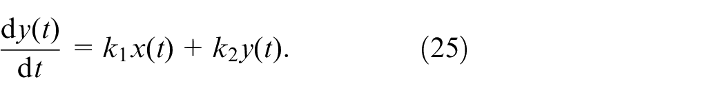
Then, through the Laplace transform of equation (25), equation (26) can be obtained.

When the initial state is zero, that is y(0) = 0, we can get:

Thus the transfer function of the controlled object is expressed as equation (28).
where
Normally, in the Tokamak experiments, the device is mainly gas puffed by the PEV-1 crystal valve. In the actual working process, due to the mechanical reasons of the valve and other ionization processes, therefore, there is a certain time delay between the piezoelectric crystal valve (the actuator) and the change of the controlled object. Here, the actuator is approximately regarded as a first-order inertial pure delay object. Experiments show that the delay time of the object is about 20 ms. Therefore the transfer function of the controlled object can be written as:
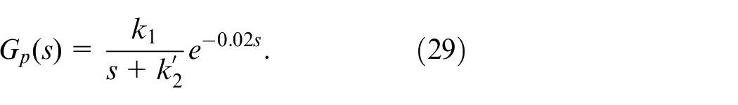
Of course, for different gas seeding types of equipment, such as SMBI, the delay time may not be 20 ms. In the design of the control system, only the transfer function of the system needs to be adjusted, which does not affect the analysis process of the PID control algorithm adopted in this work.
Algorithmic program
As mentioned above, the Tokamak plasma system is complex, and it is difficult to obtain an accurate control system model. The variation of the plasma density in the discharge process is more variable, and the plasma density feedback system is very complicated. It is difficult to establish a completely accurate and ideal mathematical model of the PEDCS based on physical and mathematical analysis. According to its principle, an approximate model is given above. To better simulate the plasma characteristics, k1 and k2 are set to 0.5 and −0.2 respectively in the simulation study.
In plasma control, RBPNN needs to be trained continuously to adjust the weight, to achieve the purpose of dynamically adjusting control parameters. The optimization steps are:
(1) Obtain the current e(k) value, meanwhile, e(k−1) and e(k−2) can also be obtained according to the saved values of the previous two moments
(2) e(k), e(k−1) and e(k−2) are brought into RBPNN neural network to train RBPNN.
(3) Check whether the iteration conditions are met, or the number of iterations has been reached.
(4) Adjust the kp, ki, and kd, otherwise continue to repeat step 3.
(5) According to equation (23), calculate the adjustment of K(k).
(6) Output the value of u(k).
(7) repeat step 1 until the end of the control cycle.
In this algorithm, unlike the standard gradient descent method, the random gradient descent method adds random factors to the gradient calculation to avoid local minima. So even if it falls into a local minimum, the gradient calculated may not be 0. In this way, it is possible to jump out of the local minimum and continue the search.
In practical PEDCS, the gas seeding system may use a piezoelectric crystal valve or SMBI. According to the requirements of the control system, the control cycle is set to 0.1 ms. In the actual neural network, we set the number of iterations of parameter adjustment not more than 50 times, or the value of convergence parameter EPS is 0.001, which can meet this control cycle in practical use. Because the industrial computer is employed for the density control system, the execution time of its algorithm is to some extent related to the configuration of the industrial computer. The higher the configuration, the faster the running speed, and the less time required for algorithm execution.
Results and discussions
For a better understanding of the control effect of the adapted control algorithm, the improved PID control algorithm is compared with the conventional PID control and model-free control algorithm using the above-mentioned control model. Figure 6 shows the response results and relative errors of the system. With the unit step and the pulse input, the simulation results of the control algorithm are shown in Figure 6(a). Setting the unit step input from 0 to 1.0 s, the response time of the proposed PID controller is smaller than that of the conventional PID controller and then keeps stable at t = 0.2 s. On the contrary, the conventional PID control reaches a stable state of about t = 0.4 s. The rise time difference between model-free control and the method proposed in this paper is not large, but its overshoot is smaller than the method proposed in this paper. Of course, by constantly adjusting parameters, the performance of the two control methods is relatively close. To further verify the adaptability and tracking speed of the control algorithm, a wide pulse with a width of 0.7 s and an amplitude of 0.5 v is put to the input at t = 1.0 s. The relative errors of the response time of the system are also shown in Figure 6(b). Figure 7 is the detailed results of Figure 6 from 0.95 to 1.75 s. When the step signal amplitude decreases, the response rise time of the system also decreases, which is also the basic characteristic of the control system. Through the comparison with the conventional PID controller, it is demonstrated that the proposed PID controller can adapt to the input change more quickly and that the tracking ability is improved. At the falling edge, the algorithm described in the article is faster than the normal PID control algorithm. The overall performance of the model-free control algorithm is very close to the method proposed in this paper.
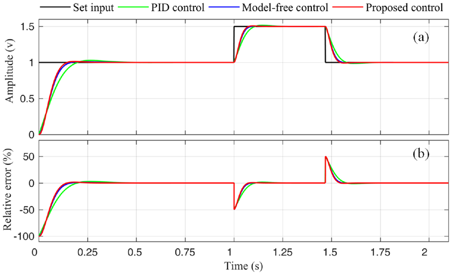
The response results and relative errors of the system: (a) simulation results between the proposed controller and the conventional PID control and model-free control and (b) the relative error of the response of the system.
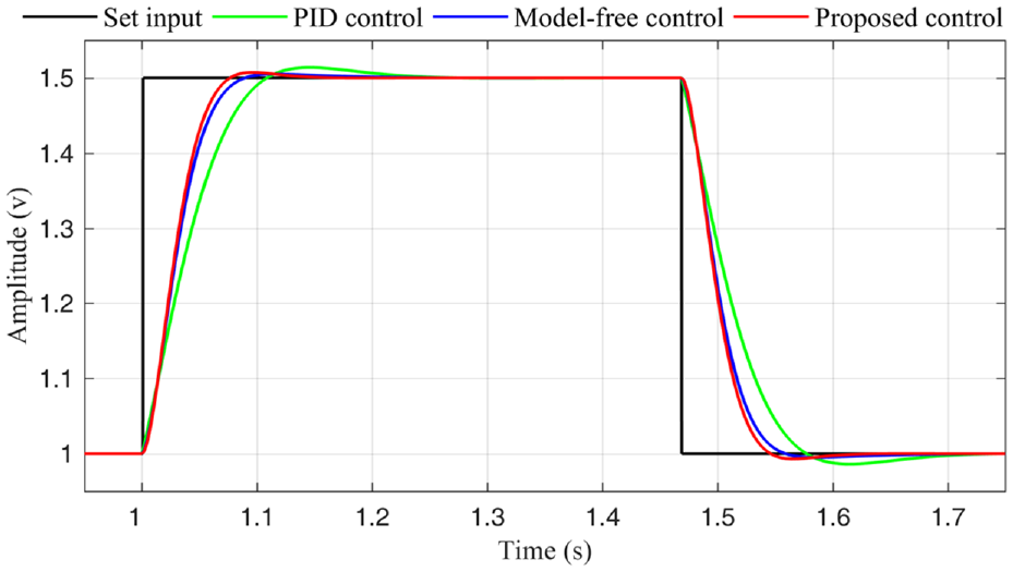
The detailed results of Figure 5 from 0.95 to 1.75 s.
In the actual plasma electronic density control system, the desired density value cannot be in the form of a step. The plasma density generally includes an ascending phase, a flat top phase, and a descending phase. Here, a density feedback control simulation similar to this type is performed using the algorithm. Figure 8 is the simulation results. As shown in Figure 8(a), the simulations show a good signal-tracking control effect compared with the conventional PID control algorithm. It can also be seen from Figure 8(b) that the maximum relative error of the proposed method is less than 3%. In the stage of relatively stable density change, the relative error of the control system shall not exceed 1%. Based on the above simulation results, it is demonstrated that the proposed control algorithm improves the adaptability, real-time performance, and stability of the system.
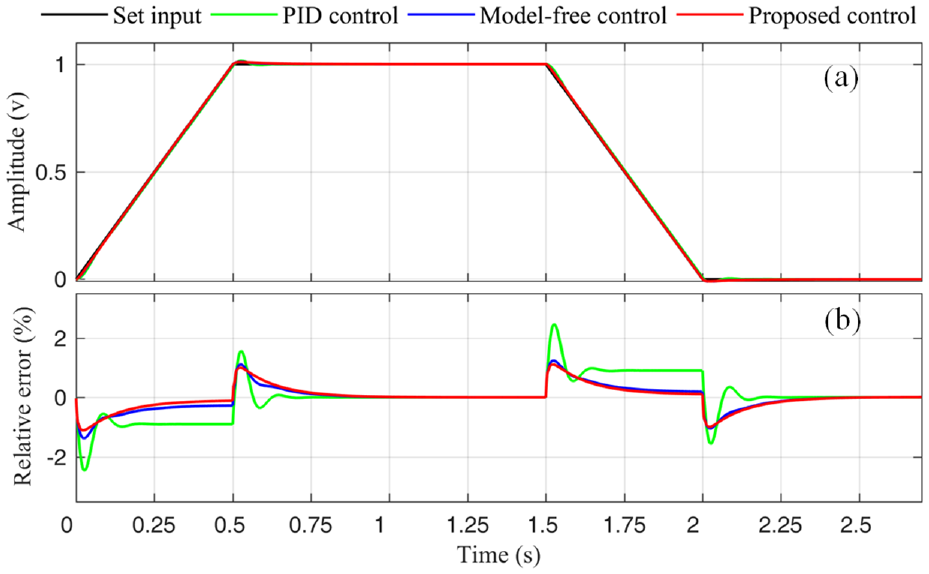
Comparison between two PID control algorithms and model-free control: (a) simulation results with the simulated three density phases and (b) the relative error of Simulation results of the system with different control algorithms.
Summary
Achieving intelligent, precise control of plasma electronic density is the expectation of nuclear fusion scientists. The composite control technology with multi-technology crossover will also become the future development direction. Due to the complexity of DFCS on the Tokamak device, the basic control algorithm is often chosen as the PID algorithm. However, because of the limitations of traditional PID, the optimization of the algorithm starts from the aspect of automatically adjusting the PID control parameters. Therefore, this work takes Tokamak devices as the object and further explores the PID parameter self-tuning algorithm applicable to the plasma electronic density control of the Tokamak device, and introduces the neural network theory in the research process. According to the mechanism model analysis of the plasma density object, an adapted single neuron PID control algorithm with the RBFNN tuning is studied and successfully applied in the Tokamak PDCS. From experimental results, it can be seen that the neural network is achievable when it is applied to the Tokamak device as a control algorithm, and it has certain effects on parameter tuning. The principle and design of the intelligent control algorithm are described in detail in this paper. The intelligent controller enables the system to optimize the PID parameters online in real-time with the density state in the discharge process. The simulation results show that the proposed algorithm achieves a good control effect and improves the control performance of the system.
The research on an artificial neural network system with information processing mechanisms can provide new control means for a large number of complex control objects in engineering, and improve complex control quality under variable conditions. The intelligent control algorithm of plasma electronic density proposed in this paper provides a theoretical basis for the development of the system. Of course, the control algorithm needs further development and optimization. In this paper, some experimental results of the proposed control method are compared with the PID control algorithm to verify the performance of the system. This paper gives the detailed design process and verification results of the proposed algorithm. Of course, there is more work to be done in the future, that is, to apply the algorithm to the actual discharge process. In the actual process, it is also a long-term process to continuously optimize and improve the algorithm. The proposed controller will be helpful to provide a useful reference for further research, which supplements and enriches the existing intelligent controller.
Footnotes
Declaration of conflicting interests
The author(s) declared no potential conflicts of interest with respect to the research, authorship, and/or publication of this article.
Funding
The author(s) disclosed receipt of the following financial support for the research, authorship, and/or publication of this article: This work was supported by the Fundamental Research Funds for the Central Universities (No. JZ2019HGTB0082) and the National Magnetic Confinement Fusion Science Program of China (No. 2015GB102004).