
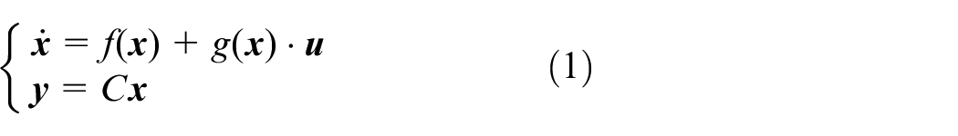
Abstract
The proton exchange membrane fuel cell gas control has been one key point in fuel cell management systems. The complexity and coupling of the air management system make it difficult to achieve precise air intake adjustment. In this paper, an accurate joint control method for the air flow and pressure regulation is proposed. The nonlinear mathematical model of the air management system is developed to describe the output characteristic and state change. Based on this, the feedback linearization method is proposed to obtain the direct correspondence between control variables and controlled variables. In addition, to solve the problem that the controlled variables cannot be measured directly, an extended state observer is applied to estimate the stack cathode pressure. The sliding mode predictive control method is proposed to control the oxygen excess ratio and cathode pressure simultaneously. The relative order of the system is used to design the sliding mode surface, and the corresponding predictive model is proposed. The results obtained by simulation experiments show that pressure and mass flow have little effect on each other through decoupling. The proposed algorithm has been verified to have high precision, fast response, and robustness through comparative experiments.
Keywords
Introduction
In the face of the current energy crisis and increasing environment pollution, clean new energy sources have gradually replaced traditional energy sources such as oil and coal, and have received attention and development from many countries in the world. Among them, fuel cells are one of the most promising power generation technologies due to the superiority of high power generation efficiency, low pollution, high specific energy, and high reliability.1,2 With the continuous maturity of fuel cell technology in recent years, there is a broad prospect for the commercial application of fuel cells. In the transportation field, new energy vehicles with fuel cells as their main power sources are considered to be able to replace traditional fuel vehicles. The proton exchange membrane fuel cell (PEMFC) is one of the most applied electric energy sources for electric vehicles because of its low pollution and fast start-up.3,4
The safe and efficient operation of a fuel cell stack is inseparable from its auxiliary system, which adjusts the reaction gas inlet, gas discharge, the temperature, and humidity of the reactor in real time according to the power required by the load, so as to ensure that the reactor runs in its ideal working environment. 5 The air management system is an important and complicated sub-part for PEMFC system. It is used to regulate the suitable air flow rate and pressure in stack cathode to meet the power demand and meanwhile maintain a stable stack pressure environment. However, the air management system is a highly nonlinear, time-delayed, and strongly coupled system, which is difficult to control it accurately and robustly.
The oxygen excess ratio (OER) control is a critical point in terms of fuel cell safe and efficient control. The OER characterizes the oxygen flow into the stack cathode. 6 The oxygen starvation phenomenon is usually caused by system inertia and occurs when the load current changes rapidly, which results in reduced output performance and accelerated fuel cell decay. Many literatures have studied the optimal control problem of OER. The feed-forward control was first proposed by Pukrushpan in Iqbal and Amin, 6 which is an open loop control. The problems with this method are the need to obtain controller parameters offline, poor anti-interference, and long response time. The proportional-integral-differential (PID) control is the most commonly used algorithm in industrial process. It is model-independent and easy to implement. However, the disadvantages of PID method are narrow controllable range and large overshoot. Hence, many enhanced algorithms were proposed to improve the performance of PID controller. For example, Baroud et al. 7 proposed a novel hybrid controller, which consists a fuzzy logic controller and a self-tuned PID controller. The results indicated that the hybrid controller had better performance than PID controller. AbouOmar et al. 8 built a fractional order fuzzy PID controller for the OER control, and the neural network was employed to optimize the algorithm. The proposed method showed good set point tracking ability and robustness. Xu et al. 9 developed a nonlinear PI algorithm to simultaneously regulate the air flow, pressure and humidity. The model predictive control is another useful method for OER control, which performs high accuracy and fast response. 10 Abdullah and Idres 11 proposed a constrained model predictive control (MPC) method to regulate the air flow rate and avoid the oxygen starvation. Nonlinear MPC,12,13 generalized predictive control, 14 explicit MPC, 15 robust MPC, 16 and other improved MPC algorithms17,18 were also widely applied in the OER regulation. In addition, the sliding mode control is an outstanding method for fuel cell system control due to its excellent non-linear processing ability, good robustness and fast response. In Deng et al., 19 the high-order sliding mode observer was employed to estimate the system internal states and realize the OER closed-loop feedback control. Liu et al. 20 used a model-based robust control method for air feed control based on the sliding mode theory, and the method was verified through a hardware-in-loop bench. Other kinds of methods, such as globally linearizing controller, 21 data-driven methods, 22 and adaptive control, 23 were applied and proven to be effective for the OER control problem.
The gas pressure regulation is another essential item that also cannot be ignored in the fuel cell air management. A higher pressure can improve the system output power, which, however, also causes an increase in the parasitic power and reduces the system efficiency. In addition, unstable pressure fluctuations and high pressure ripples may cause damage to the proton exchange membrane, which easily cause surge of the air compressor and make the system ineffective. 24 On the other hand, the gas pressure and flow are strongly coupled, especially in the high-power fuel cell system. Adjusting the OER will cause the cathode gas pressure to change accordingly, which has a negative impact on the stability of system safety and output performance, vice versa. So the joint control problem of pressure and air flow can better guarantee the working performance of the system. Most of the literatures mentioned above have not discussed the changes in pressure during OER control. Xu et al. 9 designed a multivariable control strategy for the air feed system. The control targets were determined through the offline tests, and the adaptive second order sliding mode controller was developed for the pressure and flow control. Liu et al. 25 proposed a double closed-loop fuzzy-PID control based on feedforward compensation decoupling for the air flow and pressure control, and thus the steady-state error was decreased. Da Fonseca et al. 26 designed a nonlinear control strategy to regulate the air-feed variables based on differential flatness control theory. In Zhao et al., 27 the neural network was applied to model the air compressor, and the sliding mode control was developed to control the flow and the pressure based on twisting and super twisting algorithm respectively. In Liu et al., 28 a dual-loop control method was proposed to control the air mass flow and pressure based on an easy-to-implement air system decoupling controller. In general, the above literatures show good control performance of the proposed methods. However, research in this area is still scarce. And the high non-linearity, mathematical complexity and the parametric coupling of the system are always difficult to handle and make the control strategy computationally expensive.
Based on the above discussion, in order to solve the multivariate control problem of the fuel cell air management system, improve control accuracy and dynamic performance, this paper focuses on the problem of the joint regulation of air pressure and flow, then proposes a corresponding control framework based on predictive control. The main contributions are summarized as follows:
(1) The control-oriented multi-input-multi-output model is developed to describe the working characteristics of the fuel cell air management system. An input-output feedback linearization method is proposed to decouple the model. The direct correspondence between the control variables and controlled variables is obtained through decoupling.
(2) An extended state observer (ESO) is used to estimate the cathode pressure. The observer uses a single measurement for state estimation, which is simple in structure and easy to implement.
(3) A sliding mode predictive control method is proposed to control the OER and cathode pressure simultaneously. The relative order of the system is used to design the sliding mode surface, and the predictive model of MPC is proposed based on this. The optimal control inputs are obtained in real time through a rolling optimization algorithm.
(4) The proposed method has been validated through simulation and comparative experiments. The proposed algorithm has been verified to have high precision, fast response, and robustness through simulation and comparative experiments.
The structure of this paper is listed as follows: section 2 introduces the simplified mathematical model of the fuel cell air management system. Section 3 describes the control objective and control algorithm design. Section 4 gives the simulation results, and the comparative experiments are showed to verify the superiority of the proposed method. The conclusions are summarized in Section 5. Finally, the calculation results of formulas in the paper are given in Appendix.
Modeling of fuel cell air management system
The structure of PEMFC air management system is shown in Figure 1, which mainly contains a fuel cell stack and two auxiliary subsystems: the hydrogen management system, which is used to feed proper fuel in the anode; the air management system for air supply and exhaust in the cathode. The water management the thermal management system which are independent of the air management system, are not discussed in this paper. Aiming at a better control of the air flow and pressure, the air management system is mainly analyzed and modeled in this paper. Irrelevant parameters and variables are idealized to eliminate their impact on system performance and simplify the modeling process. In this regard, the following assumptions are made: the temperature and humidity of the fuel cell stack are well controlled at their ideal values and the hydrogen is perfectly supplied. 19 The time response of temperature and humidity are much slower than the gas pressure and flow rate, and the hydrogen supply is independent of the air system, so the above assumptions are reasonable.
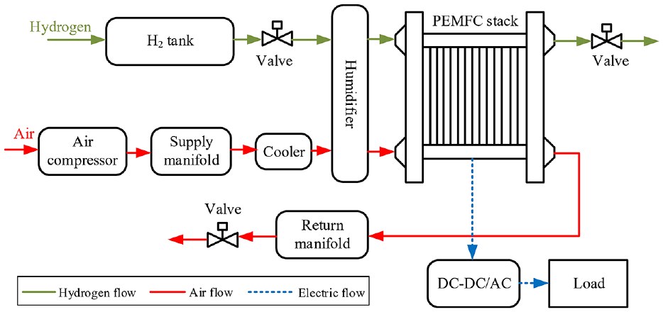
The diagram of the PEMFC air management system structure.
The air management system of PEMFC includes an air compressor, a supply manifold, a cooler, a return manifold and a backpressure valve. The air compressor is used to provide a proper air flow rate based on the power requirements and cathode pressure. The backpressure valve is for exhausting the remaining gas and maintaining the stack cathode pressure environment. The fuel cell performance is directly related to the gas pressure and mass flow. First, the gas pressure in the stack plays an important role for maintaining the output voltage. Inappropriate pressure and air flow will lead to reduced output performance and insufficient oxygen supply. Second, as the load demand changes quickly, large jitter in pressure and flow may damage the proton exchange membrane. In addition, the oxygen starvation phenomenon may occur during fast load variation due to system inertia, which means the system cannot provide enough oxygen for electrochemical reaction. And oxygen saturation occurs if intake air flow is too large, which will lead to high parasitic power and reduce the system net power. So realizing an efficient and fast response air management method is an essential work in fuel cell management system.
The ninth-order Pukrushpan model 6 was proposed primarily to describe the dynamic behavior of the gas supply and the electrical performance of the fuel cell stack. The model takes the compressor voltage as the input to control the air flow rate. However, when it comes to the joint control problem of flow and pressure of the fuel cell stack, this model cannot meet the controller design requirements. To meet this, the Pukrushpan model is further developed in this paper. The proposed model only considers the part of the air system and the dynamic changes of pressure and flow, and then reduces the original model to a sixth-order model. In addition, the opening degree of the backpressure valve is added as a model input to adjust the cathode pressure. The mathematical model of the fuel cell air management system can be expressed by the following nonlinear state space equation:
where the state vector
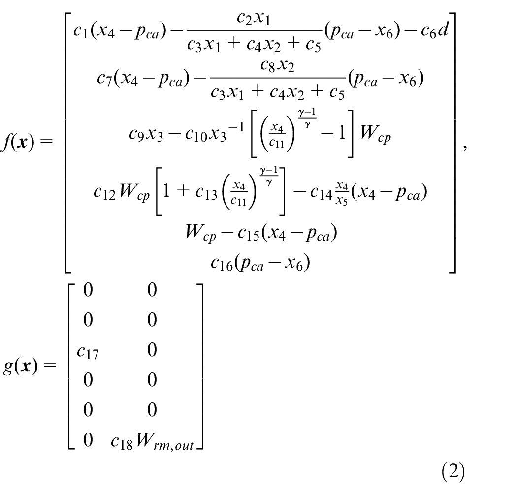
In equation (2), c1–c18 are model parameters obtained from the Pukrushpan model. d represents the fuel cell current Ist, which is considered as a known disturbance in the model. Cathode gas components include oxygen, nitrogen and water vapor, other trace gas elements are ignored. pca represents the pressure in the stack cathode, which can be calculated by equation (3):

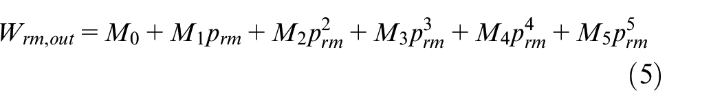
where c1–c18, and b1–b3 are model parameters and their calculation method is shown in the Appendix. The three items in equation (3) stand for oxygen partial pressure, nitrogen partial pressure and vapor partial pressure in the cathode. Wcp represents the mass flow rate out of the air compressor, which is related to the compressor outlet pressure and rotating speed and is obtained from the flow-speed-pressure map in the previous model. Wrm,out represents the mass flow outward from the backpressure valve and is modeled by the nozzle function. 6 In order to reduce the complexity of the model and facilitate the design of the controller, we use polynomials 29 to fit the above compressor map and the nozzle function, shown as equations (4) and (5), where B0–B5 and M0–M5 are constant coefficients obtained by curve fitting tool.

The control objective and extended state observer description
Control objective description
The control object of the air management system is to adjust the pressure and flow of the air in the stack cathode to ideal values. We try to control the fuel cell stack cathode pressure pca to the expected value and reduce the response time. For the mass flow control, the OER is used to reflect the inlet air flow, which is defined as:
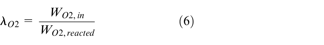
where WO2,in represents the oxygen mass flow into the cathode, WO2,reacted represents the oxygen flow that is actually consumed in the electrochemical reaction. WO2,in is given by a simplified formula, where the gas flow is approximately proportional to the pressure difference, as shown in equation (7):

where
The reacted oxygen flow WO2,reacted is calculated by equation (8):

where N is the fuel cell number, MO2 is the oxygen mole mass, F is the Faraday constant. Substituting equations (7) and (8) into (6), the OER is related to the state x4 and cathode pressure pca.
Based on the above calculation, define the system control objective:
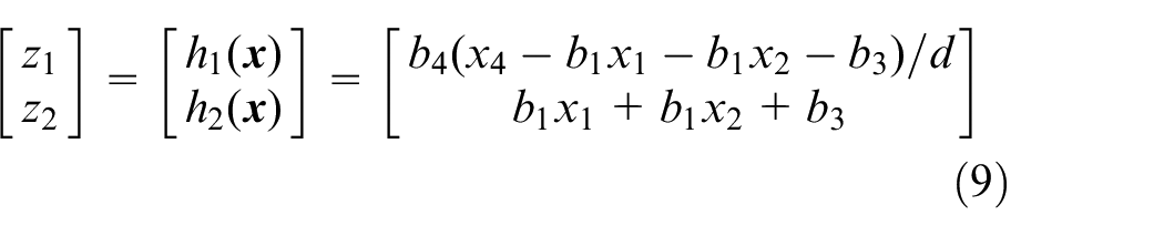
where
Extended state observer for cathode pressure
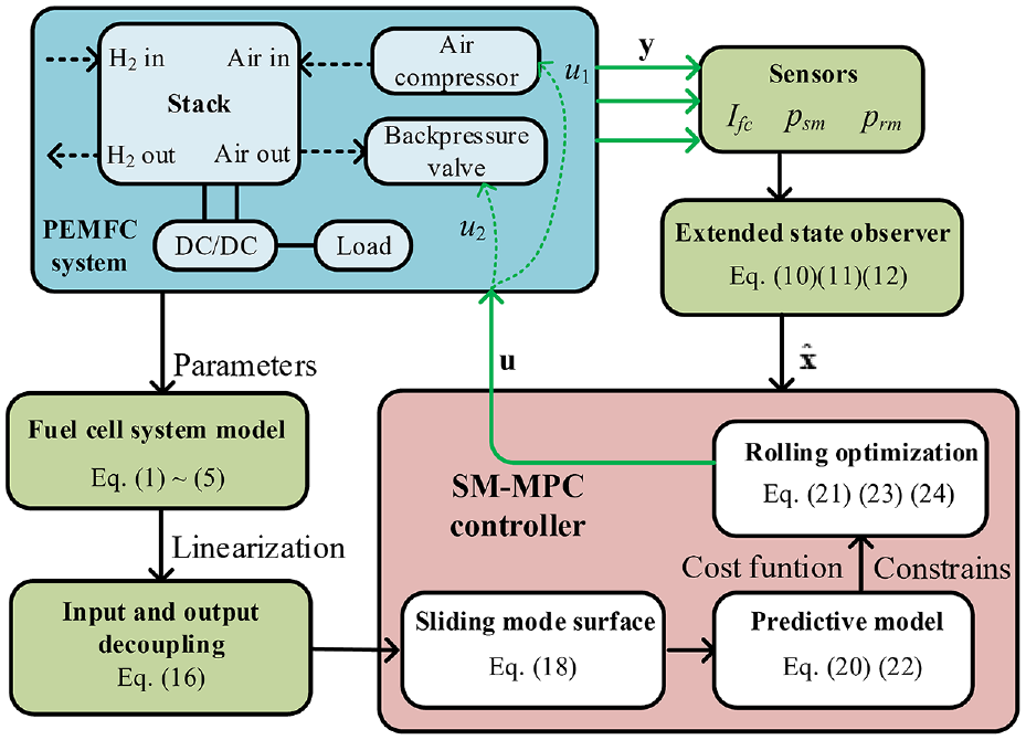
The control objectives: OER and pca, are unmeasurable. And the OER is directly related to pca from equations (6) to (8). Therefore, in order to observe the values of OER and pca, an ESO is designed to estimate the cathode pressure in this part. The ESO is developed from the Luenberger observer and is used for estimating the unknown disturbance in a nonlinear system. ESO is essentially a high-gain observer with the advantages of simple structure, easy implementation, and anti-interference.
We propose a first-order ESO for the pressure estimation. Consider the sixth term of equation (2) separately and extend the cathode pressure pca to be estimated to a new state x7, then the state function of x6 can be rewritten as:
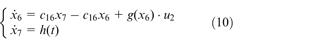
where
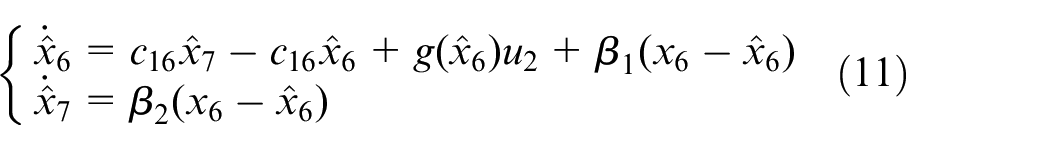
where
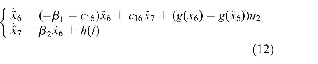
In order to ensure the convergence of the ESO, the polynomial
The proposed sliding mode predictive controller
In this section, the joint controller for air flow and pressure is proposed. As the OER and cathode pressure control are coupled, the first thing to do is to decouple the controlled variables. So the feedback linearization method is introduced. Then the framework of the model predictive controller is designed. The idea of sliding mode control is integrated into the model predictive control, and the predictive model is designed by using the sliding surface.
Decoupling based on feedback linearization
The feedback linearization method is applied to linearized the model and obtain the direct relationship between inputs and the control objective
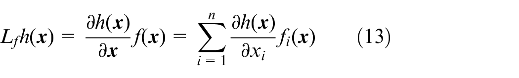
1. The Lie derivative is defined as the derivative of a scalar function along a vector field. The Lie derivative of the output function h(
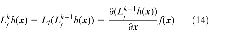
Similarly, the multiple Lie derivatives can be recursively defined as
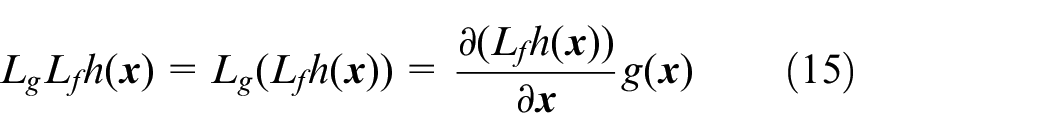
2. A multiple-input-multiple-output (MIMO) system is said to have a relative degree vector
(1)
(2) The
Based on these assumptions, we consider the performance indicator
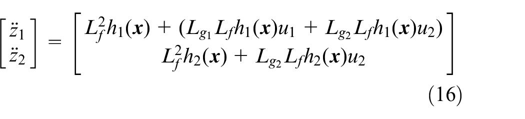
The specific expression of h1(
Define the equivalent inputs:
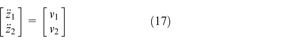
Based on equation (17), the main job is to design proper input
The sliding mode predictive controller design
The MPC is a model-based optimal control method. Its current control action is obtained by solving a global optimization problem in a finite time domain at each sampling interval. MPC has the advantages of good control effect and strong robustness, and can easily handle various constraints in the process volume. Hence it is used in this paper to solve the fuel cell air control problem. The main purpose of introducing the sliding mode (SM) control is to make MPC better adapt to nonlinear systems. Due to the highly nonlinear nature of fuel cell systems, directly applying predictive control algorithms can result in significant computational complexity. By designing the sliding mode control as the optimization objective, the control performance can be ensured, and the convergence and robustness of the algorithm to the nonlinear system can be improved.
For the fuel cell air management system equations (1), (2), and (12), define the following sliding mode surface
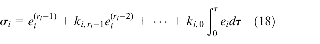
where i = 1,2, ri is the relative degree of the system, ei = zi,d−zi is the performance tracking error, zi,d represents the expected reference trajectory of zi. ki,j (j = 1,…,ri−1) is the sliding mode surface parameters to be designed. In order to make sure that the system error ei (i = 1,2) converges to 0 when the sliding mode surface

Derive the sliding mode surface along the system trajectory:
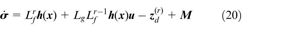
where r = r1 = r2 = 2,
Considering the following optimized indicator of the SM-MPC controller:
where Q and R are symmetric positive definite matrices, T > 0, which represents a small time interval. According to equation (20), the predictive model of
Then the control problem can be as solving the minimum of
where

The sequential quadratic programing method is applied to solve the constrained optimization problem shown in equation (23).
Based on the above controller design, the control block diagram can be summarized as Figure 2.
The proposed algorithm block diagram.
Simulation results and analysis
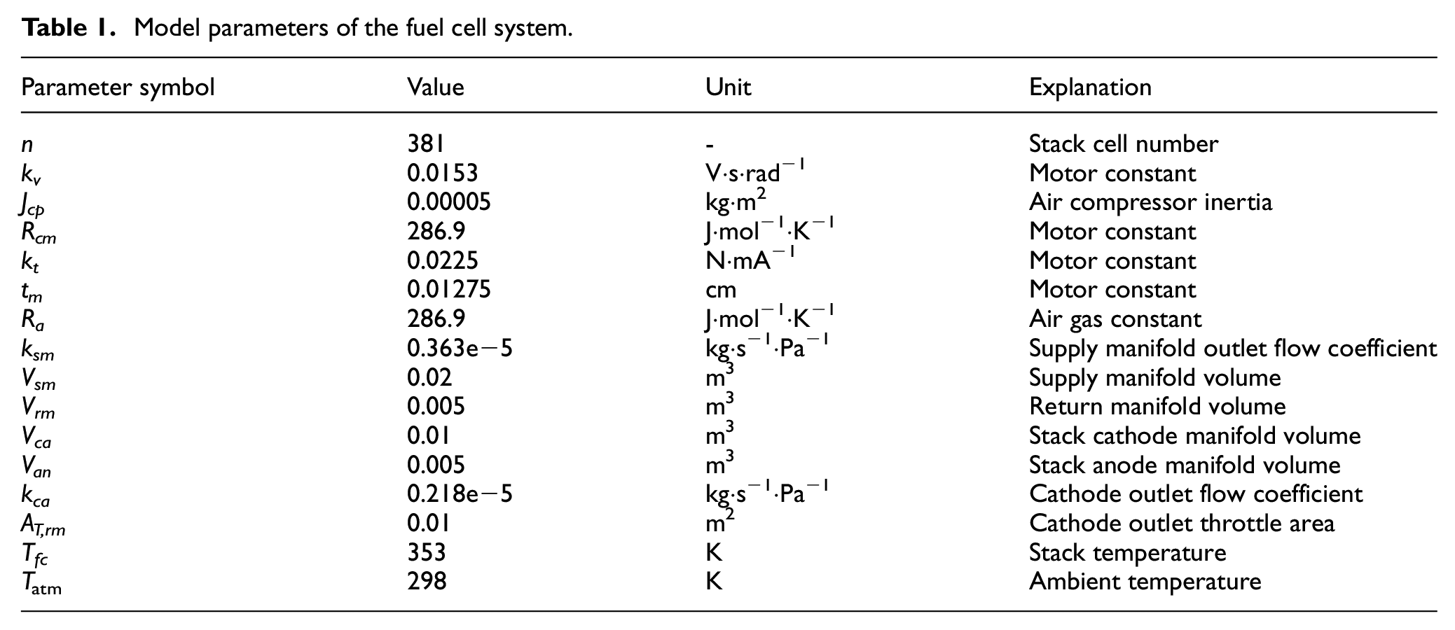
This part gives the detailed results and analysis to demonstrate the accuracy and robustness of the proposed controller. The simulation experiments were executed under the MATLAB2018b/SIMULINK8.6 environment, with the I7 core and 8G memory of the PC configuration. The vehicle 75 kW high-pressure direct hydrogen fuel cell system in Ref. 6 is applied in this paper. The main parameters of this fuel cell system are shown in Table 1. In order to more clearly show the performance of the method and eliminate the interference of unrelated factors, the assumptions listed in Section 2 are satisfied in the simulation.
Model parameters of the fuel cell system.
The results by the proposed method under a step profile
In order to verify the effectiveness and precision of the proposed method, we apply a step current profile on the fuel cell system. The current profile is shown in Figure 3(a), where the fuel cell is working in high power range. In addition, to further test and verify the robustness of the proposed method, the zero mean white noise is added to the output pressure signals (psm and prm) to simulate the sensor measurement noise, 30 which is shown as Figure 3(b).
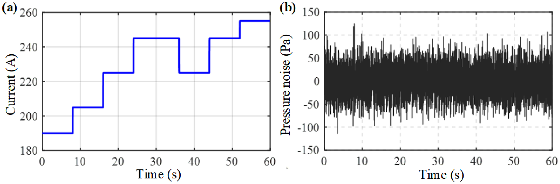
(a) The step current profile and (b) the pressure measurement noise.
In this condition, we set the control targets are: z1, d = 2, z2, d = 2.1 bar, which means the fuel cell stack pressure is fixed, and the OER is expected to be 2 during the work time. In a real application, the inlet air mass flow provided by the air compressor changes according to the load variation. And the stack pressure remains constant no matter how the mass flow changes, which helps to maintain stable stack performance and improve system safety. During the operation, controller needs to reasonably adjust the air compressor input and valve opening to suppress oxygen starvation and air compressor surge.
The OER and cathode pressure control results are shown in Figure 4. The red dot lines represent the control results by the proposed method. And the values are obtained from the ESO estimation results by equation (10). The blue lines give the control target expectations. The results indicate that the proposed SM-MPC controller can accurately and quickly control the OER and air pressure simultaneously. The small fluctuations in the estimated value that occur during the steady state phase are due to the applied sensor noise. The large mutation in the figures is caused by the load current mutation. When the load demand suddenly changes, the internal environment and states change accordingly due to the system inertia. Figure 5 shows a partial enlarged view of Figure 4, which can reflect the response time of the proposed method. The figure shows the changing trend of the system’s OER and cathode pressure when the current has a sudden change of 20 A.
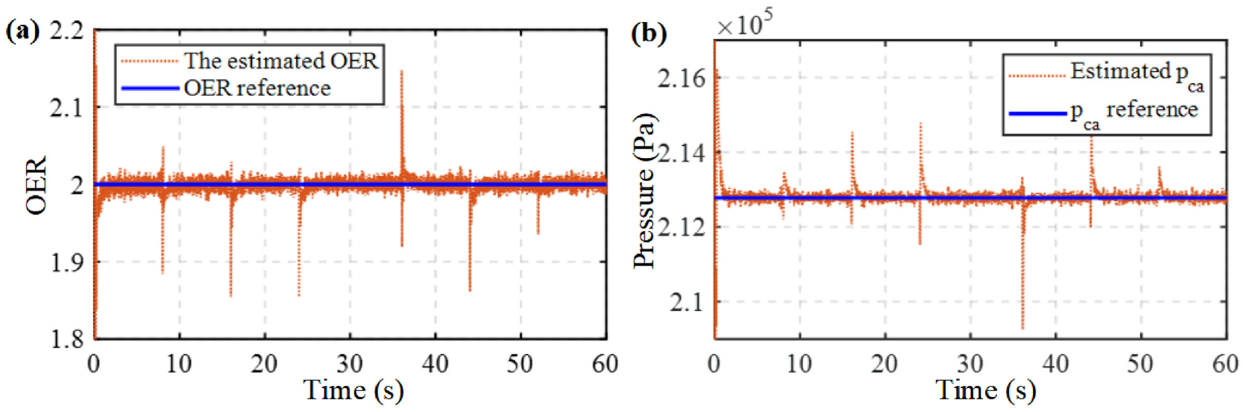
The control results: (a) the OER control results based on the proposed method and (b) the pca control results based on the proposed method.
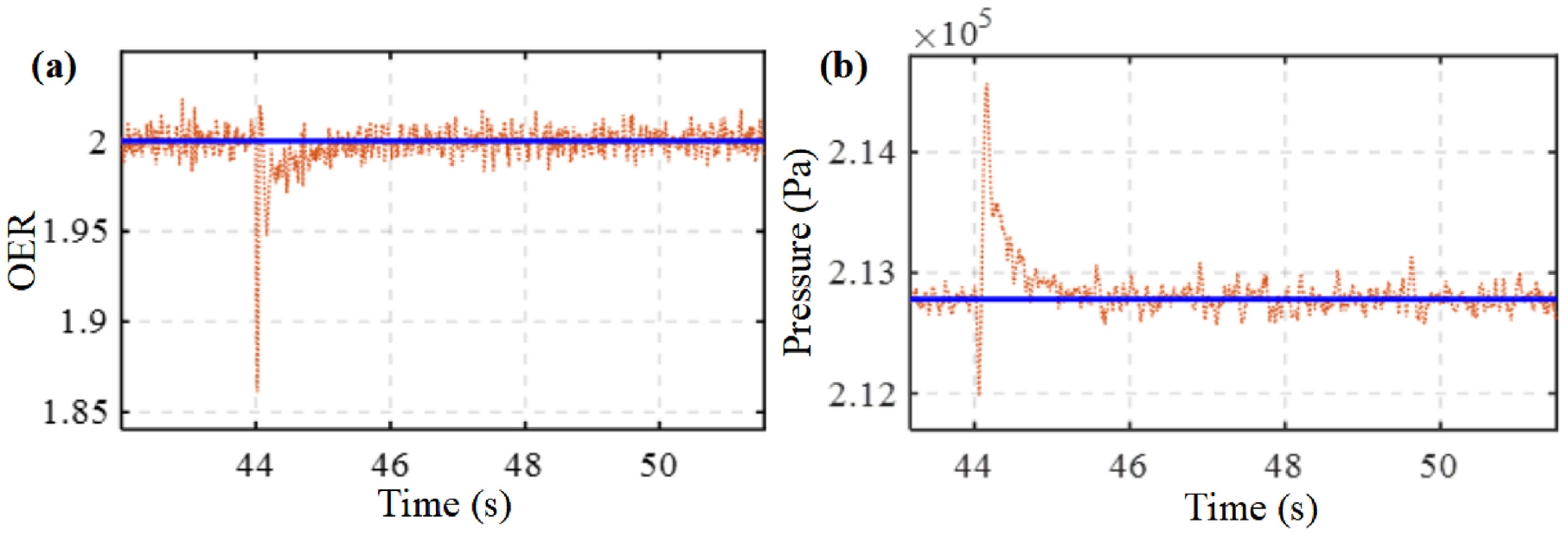
The partial enlarged view of Figure 4: (a) partial view of OER and (b) partial view of pca.
The air compressor speed and the backpressure valve opening degree are shown in Figure 6. The change trend of the two also follows the load demand. The ordinate of Figure 6(b) represents the valve opening. The value of 0.5, that is, 50%, indicates that the valve is half-open.
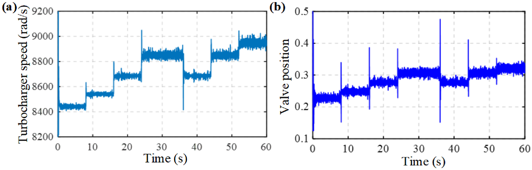
(a) The turbocharger speed of air compressor and (b) the backpressure valve position.
Comparison with the decoupled PI controller
To further demonstrate the effectiveness and quick response of the proposed method, a comparative experiment is conducted on the fuel cell simulation model. The decoupled PI controller, 31 which is a common used nonlinear control algorithm, is applied in this research. Considering equation (17), the virtual inputs of the decoupled PI controller can be written as:
where
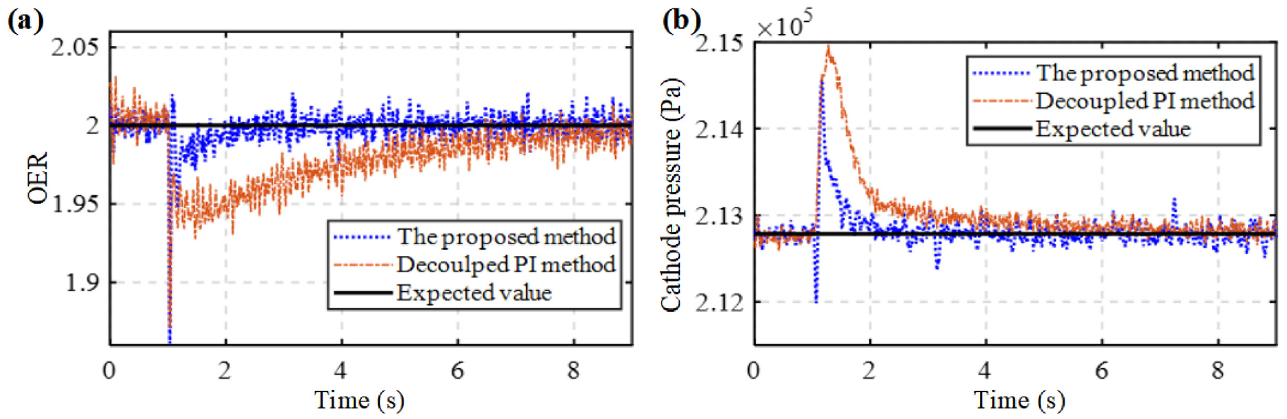
First, the response time of the controller and the overshoot performance of the control results when the load changes suddenly are compared. Consider the working condition when the load current changes from 225 to 245 A at 1 s, and the control targets are set: z1, d = 2 (the expected air mass flow changes from 0.0610 to 0.0664 kg/s), z2, d = 2.128 bar, which is equal to 2.1 atm. Figure 7 displays the control results of OER and cathode pressure. From the figure, the proposed method shows significantly better performance than the comparison method in terms of the load response time and overshoot. And the results show that pressure and flow have lower effect on each other through the proposed controller.
The results comparison when load changes: (a) the OER control results and (b) the cathode pressure results.
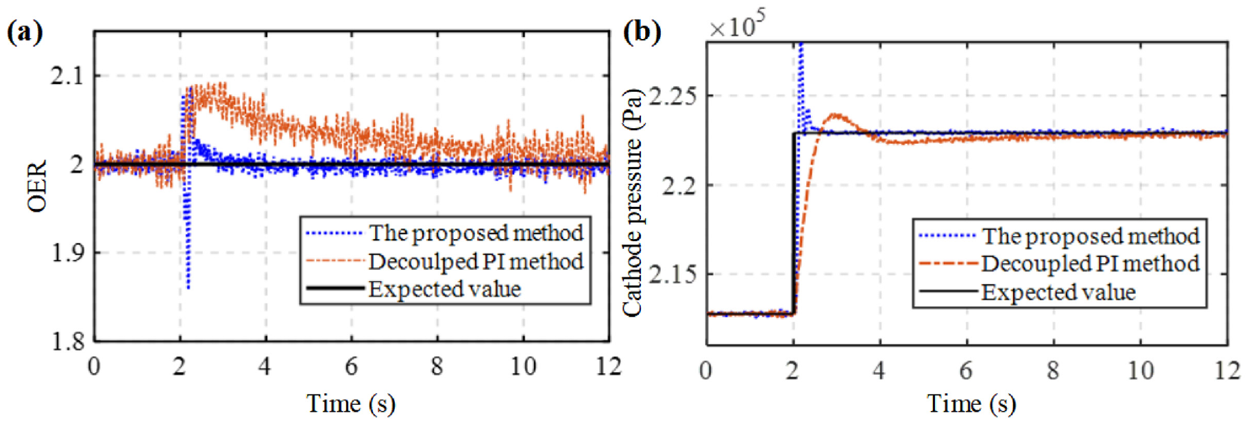
On the other hand, the performance comparison when the control command of the expected value changes is conducted. During the stable operation of the fuel cell system, if the pressure control target of the fuel cell cathode is changed from 2.128 to 2.229 bar at 2 s and the inlet air mass flow remains unchanged, test the performance of the controller in this case. The intuitive control results are shown in Figure 8. Figure 8(a) demonstrates that the OER results by the proposed method shows faster response time, and the estimated value fluctuation due to measurement noise is relatively small. The overshoot of the cathode pressure shown in Figure 8(b) is larger, however, the overshoot can be recovered quickly, and the overall control effect is better than the decoupled PI controller.
The results comparison when control target changes: (a) the OER control results and (b) the cathode pressure results.
To further quantify the control effect, the root mean square error (RMSE) and mean absolute error (MAE) indicators are used. Tables 2 and 3 shows the calculation results of the mentioned methods in the above two cases. The statistical indicators of error show that the proposed control method has better performance.
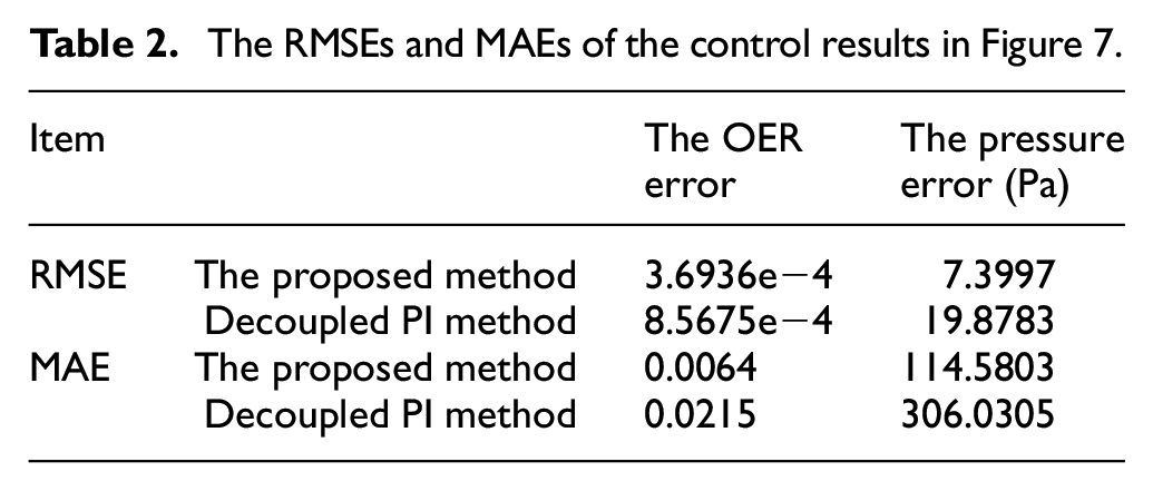
The RMSEs and MAEs of the control results in Figure 7.
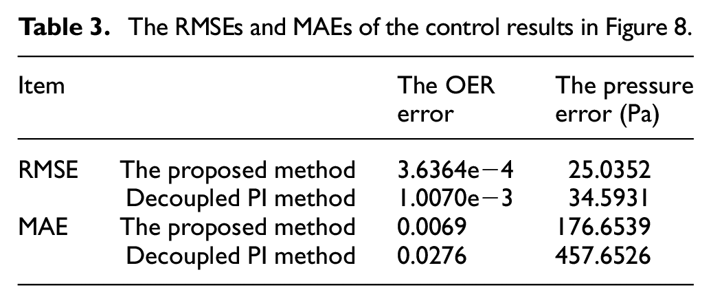
The RMSEs and MAEs of the control results in Figure 8.
The output electrical performance analysis
In this work, we aim to shorten the response time and improve the system dynamics. To demonstrate this more intuitively, the output electrical performance is discussed finally. The voltage model is referred to Abdin et al. 33 First, the fuel cell V–I curve is tested to show the model accuracy. Figure 9(a) shows a 3 kW fuel cell test bench, which was used to obtained the cell voltage by the stack voltage divided by fuel cell number. Figure 9(b) and (c) show the comparison between the test value and the fuel cell model. The results show the proposed method is accurate and effective for applying in the proposed method and the fuel cell electrical performance analysis.
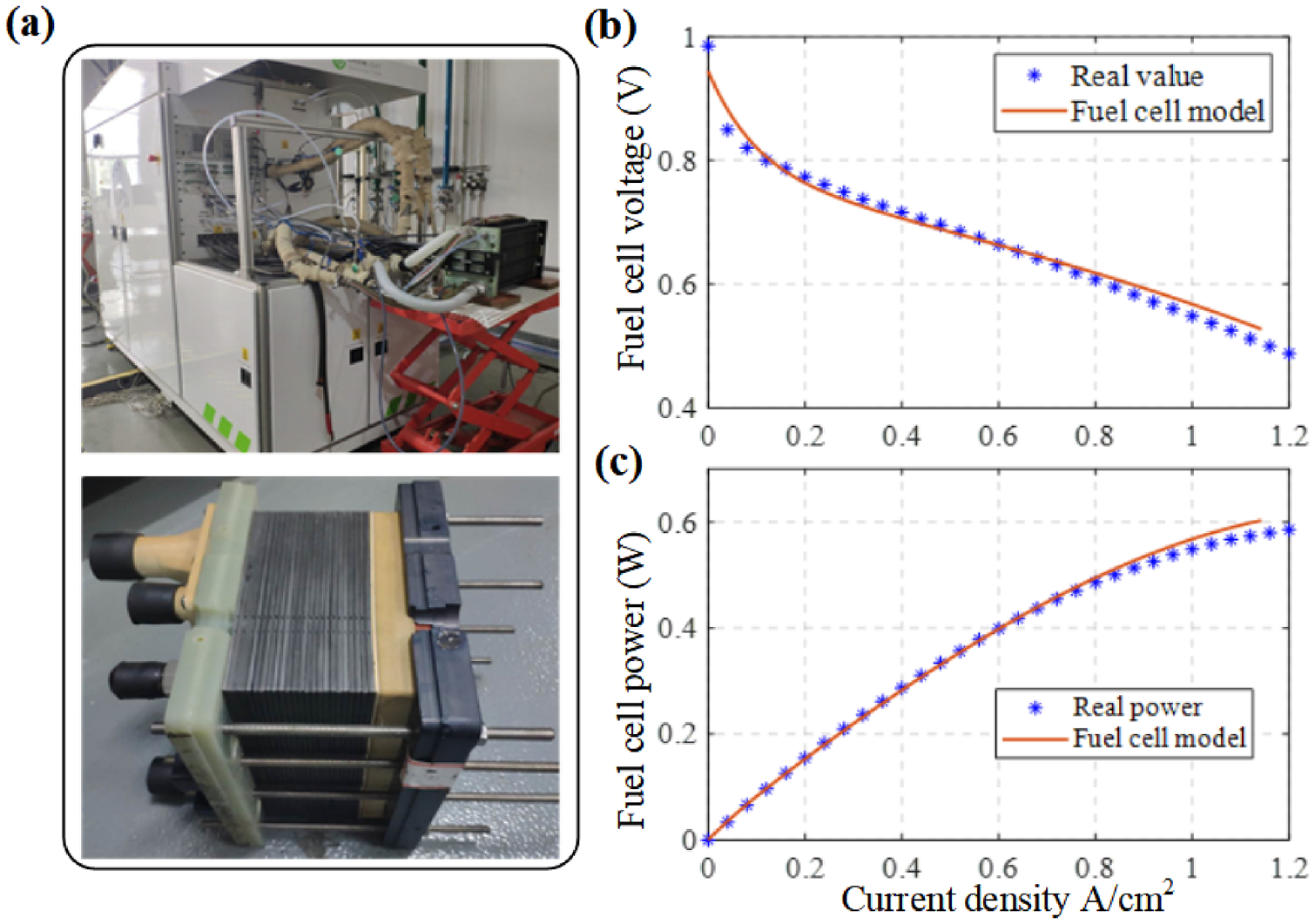
(a) Test bench, (b) fuel cell V–I curve, and (c) fuel cell P–I curve.
The electrical model shows the voltage and power variation during operation. The stack voltage Vst is shown as:

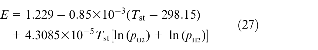
where N is the cell number, E is the Nernst voltage, the remaining three items Vact, Vohm, and Vconc refer to voltage losses during operation. The changes in gas parameters are mainly reflected in the Nernst voltage:
where Tst is the stack temperature.
Then the fuel cell power is calculated by the products of stack voltage and current:

Based on the system voltage model, Figures 10 and 11 show the corresponding voltage and power variation under the cases which are designed in Section 5.2. These figures clearly show that the change of air pressure or flow rate has a great impact on the output performance. While the fluctuation seems smaller than that in Figure 8. This is because: (1) The logarithm of voltage and pressure is positively correlated. After a logarithmic change, the fluctuation of cathode pressure in terms of voltage and power will be much smaller. (2) The cathode oxygen partial pressure is directly proportional to the mass of oxygen inside the cathode from the ideal gas function. And the mass of oxygen is related to the oxygen flow rate entering the cathode, which is positively correlated with the air excess ratio. So the curve changes and overshoot in Figure 11 are more related to changes in the oxygen excess ratio. So to sum up, the proposed controller can significantly improve the dynamic performance of the system, and reduce the control overshoot, so that the system can quickly reach stability.
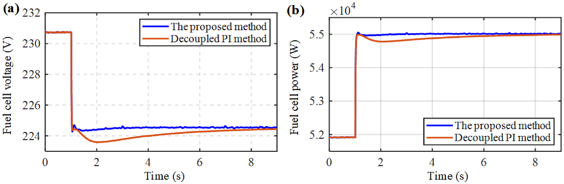
The electric performance in the case of Figure 7: (a) voltage and (b) power.
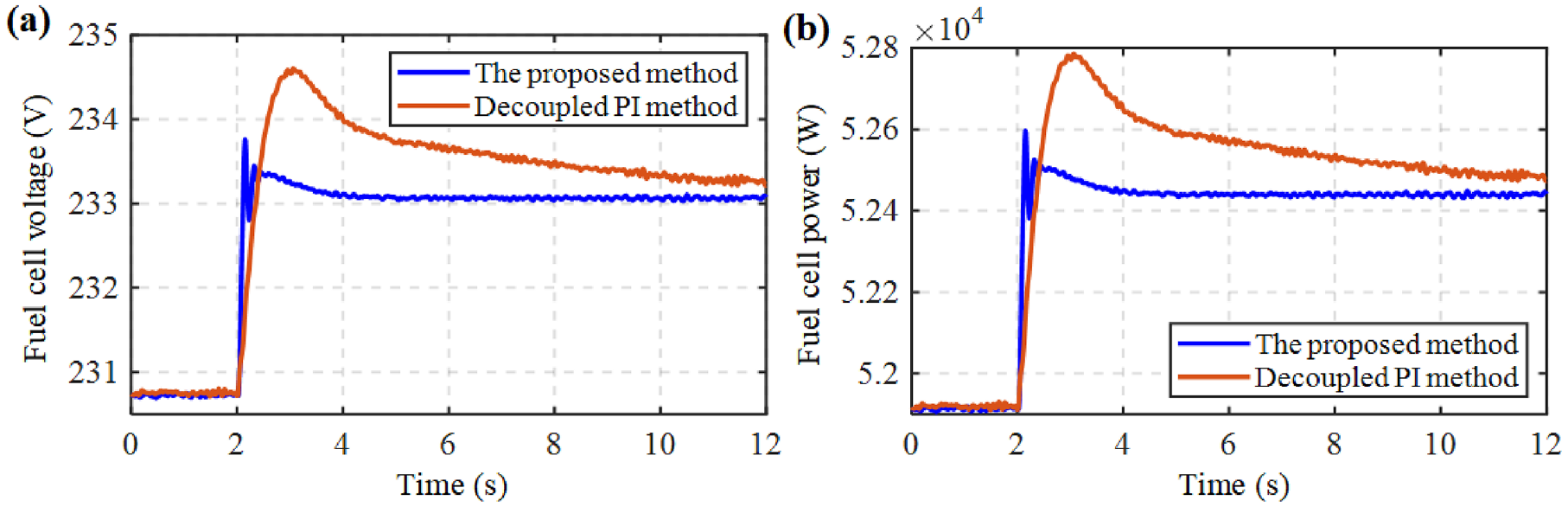
The electric performance in the case of Figure 8: (a) voltage and (b) power.
Conclusion
In this paper, a joint control method based on sliding mode predictive control for the air flow and pressure regulation of the fuel cell system is proposed. The control-oriented MIMO model is developed, which reflects the dynamic and static characteristics of the fuel cell air management system. Considering the strong coupling between gas pressure and flow, a decoupling method based on the input-output feedback linearization is proposed. In addition, because the OER and cathode pressure cannot be directly measured, the ESO is used to estimate the cathode pressure, so as to obtain the estimated value of the OER. Based on the decoupling model, the SM-MPC method is proposed to control system OER and cathode pressure simultaneously. The relative order of the system is used to design the sliding mode surface. The proposed method has been validated through simulation experiments. The results show that pressure and flow have little effect on each other through decoupling. The control errors of the pressure and OER are on the order of 10 Pa and 1e−4 respectively. The proposed algorithm has been verified to have high precision, fast response and robustness through simulation and comparative experiments.
In the future, we aim to implement the method in an actual fuel cell applications. And we will devote to further optimization of the proposed method, research on the environment and the uncertainty of system parameters, and improve the robustness and adaptability of the proposed method.
Footnotes
Appendix
The specific expression of parameters in equation (2):
where:
M O2, MN2, and Mv represent the mole mass of oxygen, nitrogen, and vapor, respectively;
ηcm is the is driving efficiency of the motor, ηcp the efficiency of air compressor, whose detailed value can be found in Pukrushpan et al. 34
p atm is the atmospheric pressure, T atm is the ambient temperature, which is set 25°C in this work;
The specific expression of parameters in equation (3):
where p sat represents the saturated vapor pressure when the stack temperature is Tst, and they meet the following function relationship 6 :
where the psat is in kPa and Tst is in K in the above function.
Other parameters can be found in Table 1.
The calculation results of the Lie derivative of the fuel cell system, as mentioned in equation (16), are shown as follows:
In the above equations, fi(x), i = 1,…,6, represent the function in the i-th row of f(
Declaration of conflicting interests
The author(s) declared no potential conflicts of interest with respect to the research, authorship, and/or publication of this article.
Funding
The author(s) disclosed receipt of the following financial support for the research, authorship, and/or publication of this article: This paper is supported by the China Postdoctoral Science Foundation (2022M722871) and the National Natural Science Foundation of China (61103396).