
Abstract
The underwater tactile force measurement was prone to cross-sensitivity, causing the difficulty in distinguishing tactile force signal with the underwater complex environment of water pressure influence. For this problem, an underwater tactile force sensor whose sensing core was based on Microelectromechanical Systems (MEMS) was designed with differential pressure typed structure. The hollow hemispherical flexible contacts located at the upper and lower end, and the hollow cylindrical shell in the middle part composed the structure of the capsule-shaped sensor. The upper flexible contact could sense the compound signal composed of water pressure and tactile force, at the same time, the lower flexible contact could measure the water pressure information. The deformation signal of the upper and lower flexible contacts could be transformed to the force sensor core’s upper and lower surfaces with silicon oil filled in the inner hollow part of the sensor. The tactile force signal could be obtained with water pressure eliminated through vector superposition method under the influence of static pressure of water. The structure and manufacture technology were introduced, and the Backpropagation (BP) neural network data regression algorithm was designed for the cross sensitivity. The experiments are conducted to demonstrate the effectiveness of the differential pressure structure in eliminating the influence of water static pressure. The results indicated that the BP neural network data regression algorithm successfully produced real tactile force signals, which is highly beneficial for the intelligent operation of underwater dexterous hand. Additionally, the sensor has an accuracy of 5%.
Introduction
The marine exploration, underwater explosion exclusion, underwater sample collection are important tasks in underwater operation, 1 and the underwater vehicle equipped with manipulator is an important tool for underwater operation. 2 The underwater robot technology is of great significance to the underwater defense technology. In the operation process, the operator located in the operation cabin of the manned submersible or in the surface vehicle, observes the operation area environment and operation objects through the camera, and remotely operates the manipulator to complete the operation task. 3 Therefore, the underwater manipulator is an important tool to realize the interaction between the underwater robot and the operation object. Notice that the harsh underwater environment such as high water pressure, 4 lower visibility even invisible, undoubtedly brings certain psychological pressure to the operator. 5 At present, the existing underwater robot is not generally equipment with tactile sensors such as “JIAOLONG” manned submersible, so that the operator’s experience plays a decisive role in the operation process. It is easy to cause the manipulator’s loose grip to miss the target or too tight grip to damage the target because of the manipulator’s low precision control without tactile sensor equipment. Due to the lack of force perception, 6 the underwater manipulator can easily grasp stationary or slow-moving target with operating experience. However, for moving object or animal, 7 it will be difficult to grasp firmly due to the lack of rapid decision-making capacity by the operator without force perception, which results in failing to complete the operation. Therefore, the underwater dexterous hand with tactile sensor equipment is an important direction for intelligent operation. 8
The design and research of underwater tactile force sensor is of great significance to the intelligent operation of underwater manipulator and the enrichment collection of underwater information. 9 With the result of the special underwater environment, the pressure caused by the water depth will interfere with the output of the tactile force sensor. If the tactile force is directly measured, the output water pressure signal and the tactile force signal will be coupled. Furthermore, it is difficult to distinguish the water depth signal and the real tactile force signal because of the compound with a big range and small range. Therefore, the non-underwater environment tactile force sensor cannot be directly employed in underwater environment. In addition, the resistance and inertial force generated by the water flow will interfere with the measurement of the tactile force sensor, and even affect the true value of the tactile force sensor output. The salinity and density of seawater have an influence on the anticorrosion, sealing and insulation of the underwater tactile force sensor, thus putting forward high requirements for the insulation and sealing of the tactile force sensor.
The fundamental principle of the underwater tactile force sensor is to enable underwater tactile measurement through the vector superposition of water pressure on the force-sensitive element. This is achieved by designing the sensor as a differential pressure structure that eliminates the impact of water pressure on the structure. Consequently, the force-sensitive element only measures tactile force information, fulfilling the intended purpose of the sensor. The underwater force sensor has the problems of server output accuracy and non-linearity, and poor repeatability. The six-dimensional force-torque sensor is installed at the manipulator joint, 10 which can avoid the waterproof design and obtain abundant manipulator force and torque information. 11 However, the six-dimensional force-torque sensor can’t judge the force generating position and easily suffers from the nonlinear coupling disturbance between each dimension, what is more, the structure is complex which brings difficulty to the calibration. In addition, the underwater tactile force sensor still has the following problems: first of all with the development of micro-electromechanical systems, the piezoresistive sensor and resistance strain sensor have developed to a certain extent, 12 among which the piezoresistive sensor have achieved certain development due to advantages such as stability and reliability. However, the piezoresistive tactile force sensor has the effect of temperature drift, which causes the output drift problem, and causes the problem of low output accuracy or poor linearity. Secondly during the use of the tactile force sensor, the true tactile force value cannot be obtained because it is not calibrated, and only an estimated tactile force signal can be obtained, which cannot meet the requirements in occasions with strict requirements for tactile force measurement. 13 Thirdly although the differential pressure type structure of the underwater tactile force sensor theoretically solves the influence of the static water pressure on the output, it is difficult to completely eliminate the cross-sensitivity problem in the real experiment. There is no relevant literature that has discussed the water pressure cause the force sensor cross sensitivity problem. Finally, the underwater tactile force sensor output drift problem caused by the water temperature is rarely recognized and seriously considered to solution.
Recently, lots of scholars have studied two-dimensional or multi-dimensional typed force sensors with abundant information acquirement, 14 the principle of which is to convert the mechanical deformation of sensing elastomer to the regular signal output such as voltage. 15 Many underwater tactile force measurement scheme and structural design have been studied for so much time. with the development of the micro-electromechanical system (MEMS) technology, the typical measurement method is to use resistance strain, and its components are consistent with the elastic structure and semiconductor sensitive components. The tactile sensors based on strain gauges realize the tactile force signal acquirement under the requirement of water pressure balance, however, each strain gauge needs to correspond to a Wheatstone bridge, which will cause circuit complexity if array sensor needed. 16 What is more, the process of attaching the strain gauge has an influence on the signal output. The optoelectronic typed force sensor in paper 17 and the fiber bragg grating (FBG) force sensor in paper 18 are proposed for the underwater force sensing, 19 however, the sensor light is easily to be effected by the external cover light and the it brings difficulty to the sensor calibration. 20
The underwater tactile force sensor is generally used in underwater manipulator to improve the intelligence and flexibility. The typical commercial manipulation system for underwater research and operation is Orion 7P deep-sea manipulator, whose gripping force in the claw reaches 4448 N, and the force sensor improves the flexible operation of the manipulator. 21 O’Brien and Lane designed a dexterous hand named AMADEUS to enhance the intelligent manipulation and flexibility for target grasping. 22 The hand utilizes a strain gauge force sensor and a PVDF (Polyvinylidene Fluoride) piezoelectric film-based vibration sensor to acquire information on force and slip. However, the hand’s overall structure cannot determine the direction of slipping or the location of force contact in a single fingertip, and it neglects sensor temperature drift. In addition to tactile force measurement, the tactile force sensor can be employed to achieve the object shape preconization, 23 the material judgement, 24 and the posture estimation 25 and so on. To enhance the information obtained during operation, Kampmann and Kirchner designed an underwater dexterous hand that incorporates piezoelectric sensors and a fiber optic sensor array on the end-effector’s planar surface. Force-torque sensors are fitted onto the joint connections to integrate the measurement system. 26 However, the sensor’s structure is complex. 27 Liang et al. proposed an underwater manipulator structure 28 that employs a novel 4-D fingertip force sensor equipped with an E-type membrane. This sensor can sample an abundance of force and torque information, exhibiting high sensitivity and good linearity in experiment verification. 29
Wang Hua proposed a cylinder multi-dimensional force sensor, 14 which measures the tactile force information of line strain and shear strain by strain gauge mounted in different directions inside the cylinder structure, 16 but the paste of the strain gauge may lose the accuracy of the sensor output. A force-torque measurement system based on optical sensing principle is installed in the fingertip by Palli et al. 17 The sensor consisted of a light-emitting diode (LED), a skin, a mirror and photodetectors, however, the installation of the emission and receiving device tended to increase the volume of the sensor. In order to achieve the accuracy and stability of underwater tactile force output under the underwater pressure environment, a lot of work should be done on zero point compensation, temperature compensation, structure design, calibration algorithm study and calibration equipment design.
The BP neural network is a large-scale and non-linear mapping system that has the ability of self-organize and self-learning. Through its own data fusion, the cross sensitivity of underwater tactile sensors is eliminated, and temperature and hydraulic compensation are performed to improve the tactile force sensor accuracy. 30 The BP network dynamically adjusts its weights and thresholds through the gradient descent method through the forward propagation of signals and the reverse propagation of errors, and realizes the purpose of nonlinear mapping through the minimum approximation error. The BP neural network algorithm is a multi-layer feedforward network and is one of the most widely applied neural network models. It can be used to learn and store a great deal of mapping relations of input-output model, and no need to disclose in advance the mathematical equation that describes these mapping relations. 31 In the era of big data, deep learning theory 32 and convolutional neural network learning 33 has made breakthrough progress, providing a strong support at the level of data and algorithm, and a certain application in non-linear data fitting.
For these problems, this paper proposed a novel underwater tactile force sensor including the structure design, measuring principal illustration, prototype design, experiment verification and the sensor data regression application with BP neural network. The designed tactile force sensor takes the shape of a capsule, uses a silicon cup as a force sensitive unit, and has a differential pressure structure. The water pressure and tactile force can be sensed on the upper side, and the water pressure can be measured on the lower side. The static pressure of the water can be eliminated by vector superposition to realize the measurement of the tactile force signal. The stress and strain distribution on the force sensitive element is analyzed. The structure and installation process of the tactile force sensor are introduced, and the BP neural network data regression algorithm is designed for the cross sensitivity of the tactile force sensor output caused by water temperature and water pressure. A four-layer BP neural is established, the temperature, water depth, and tactile force signal data are collected for offline training of the BP neural network to realize the real tactile force value output, and the sensor data regression accuracy is 5%, and the data experiment verification is carried out.
This paper is organized as follows: The underwater force sensor structure design and the measuring principle of silicon bottom as the elastomer are implemented in Section 2. The mechanical structure design and component assembly of the underwater tactile force sensor are carried out in Section 3. The experimental environment equipment and the experimental circuit system are put into effect in order to verify the performance of the tactile force sensor in Section 4. The realization of experiment data collection and diagram display, BP neural data regression are completed in Section 5, and conclude the paper in Section 6. The whole structure instruction of the paper is expressed as Figure 1.
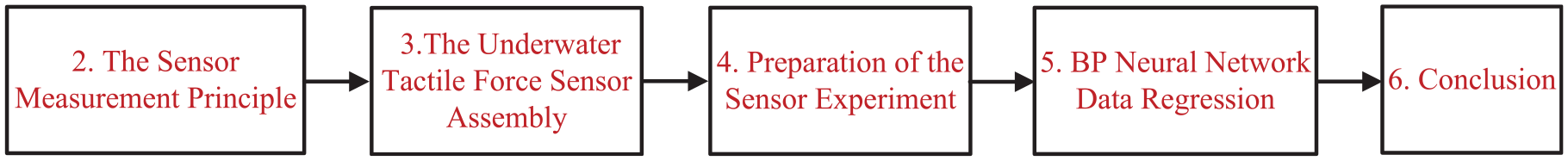
The structure instruction.
The sensor measurement principle
The sensor structure design
The sensor has a capsule shape and a differential pressure structure, and employs a silicon cup as the force sensitive element to achieve force signal measurement which is shown in Figure 2.
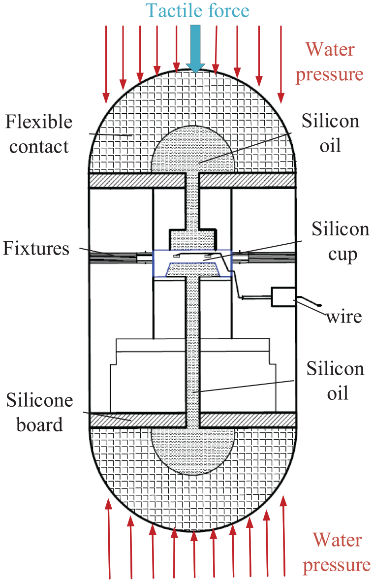
The structure diagram of force sensor.
There are two flexible contacts locating in the upper and lower sides of the capsule-type tactile force sensor, and the flexible contacts are hemispherical. The principle of human skin’s ability to perceive external information inspired the design of a soft, hemispherical, rubber material contact that can transmit external pressure information to the internal silicone oil with flexible contact deformation without any loss. The upper flexible contact converts tactile force-induced deformation into internal upper silicone oil pressure while simultaneously converting external water static pressure into internal upper silicone oil pressure. Similarly, the lower flexible contact converts external water pressure into lower internal silicone oil pressure through the silicone oil. This allows upper and lower pressure information to be directed to the dual surfaces of the silicon cup bottom, including the force measurement unit. The silicon cup bottom functions as a sensing elastomer, with its strain reflecting the deformation information of the flexible contact caused by the upper tactile force through vector superposition. The vector superposition scheme diminishes the influence of the water pressure so that it realizes the real tactile perception on the upper surface of the silicon cup bottom. The tactile force signal measurement is realized by the deformation of silicon cup bottom and four force sensitive units are distributed on the high strain zone of the silicon cup bottom. The Wheatstone bridge consists of four force sensitive units to achieve force signal output. The differential pressure structure design avoids the impact of large water depth and large water pressure on the signal output, which makes it impossible to measure the weak tactile force signal under the influence of huge water pressure.
When the tactile force sensor is not loaded with tactile force, the pressure on the upper and lower sides of the silicon cup demonstrates water pressure information, and the silicon cup is not deformed. On the contrary the tactile force is loaded, the differential pressure structure of the silicon cup eliminates the influence of water pressure, the deformation of the silicon cup is still caused by the tactile force signal and the tactile force information is still achieved.
The thinner part in the middle of the silicon cup and the bottom of the silicon cup can be regarded as a square diaphragm, which is the part that mainly bears pressure and produces deformation, and it is the dominant of realizing underwater tactile force measurement. As the measurement core of underwater sensor, the silicon cup has the advantages to the strain gauge. Four force sensitive units are corroded in the high stress area at the bottom of the diaphragm through the silicon cup corrosion process as a variable measuring resistor, which avoids accuracy loss through the strain gauge’s bonding process. The linear output map between the force sensitive element’s strain and the Wheatstone bridge resistance changes can be implemented with the load pressure measurement.
The Wheatstone bridge principle
In order to obtain the greatest possible sensitivity, the force-sensitive components are mounted on the high-stress area, where the stress is high and the distribution is concentrated. The bottom of the silicon cup is a pressure sensitive part, and its deformation under force loading will change the resistance of the varistor arranged in the sensitive area, and realize the sensor signal output. The maximum sensor sensitivity can be obtained by arranging the force-sensitive element at the place where the stress is the greatest at the bottom of the silicon cup. The stress and strain verification analysis of the square thin plate at the bottom of the silicon cup is carried out by the numerical calculation method, and the stress and strain distribution at the bottom of the silicon cup are obtained. 34
The high stress area at the midpoint of the quadrilateral at the bottom of the silicon cup is distributed by photolithography, sputtering, corrosion and other processes to distribute four force-sensitive units, and the four force-sensitive units are built into a Wheatstone Bridge circuit, as shown in Figure 3.
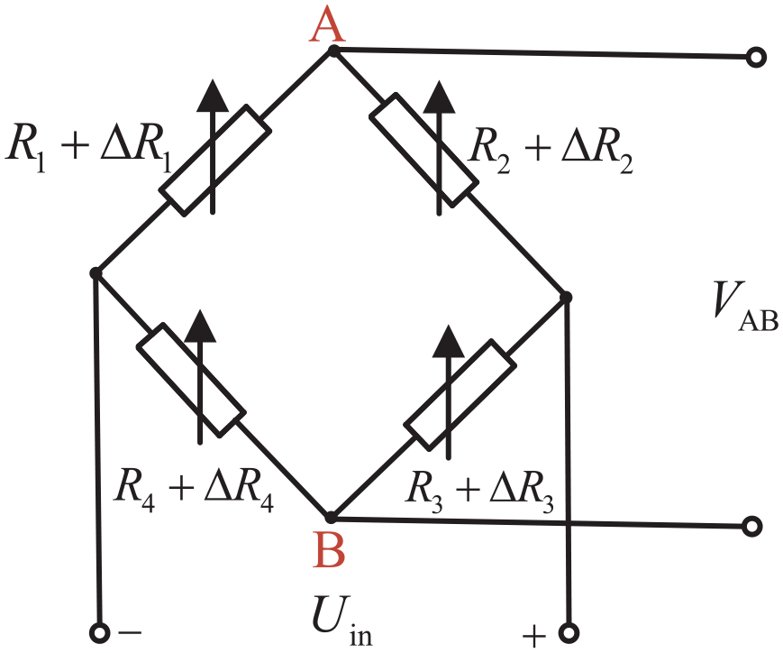
The schematic diagram of force sensor full-bridge circuit.
Among them,
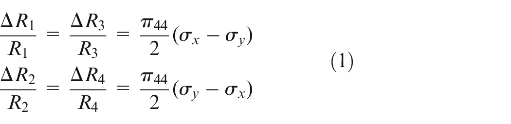
When the input voltage of the Wheatstone bridge is
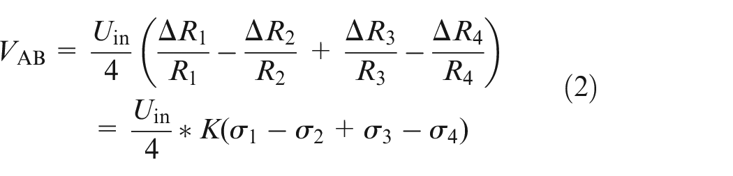
where
The underwater tactile force sensor assembly
The manufacturing process and installation technology of the tactile sensor play an important role in the output performance such as sensitivity and linearity. According to the measurement principle of the differential pressure structure described in Section 2, the structure of the underwater tactile force sensor is designed and manufactured, and the profile of the designed underwater sensor is expressed in Figure 4.
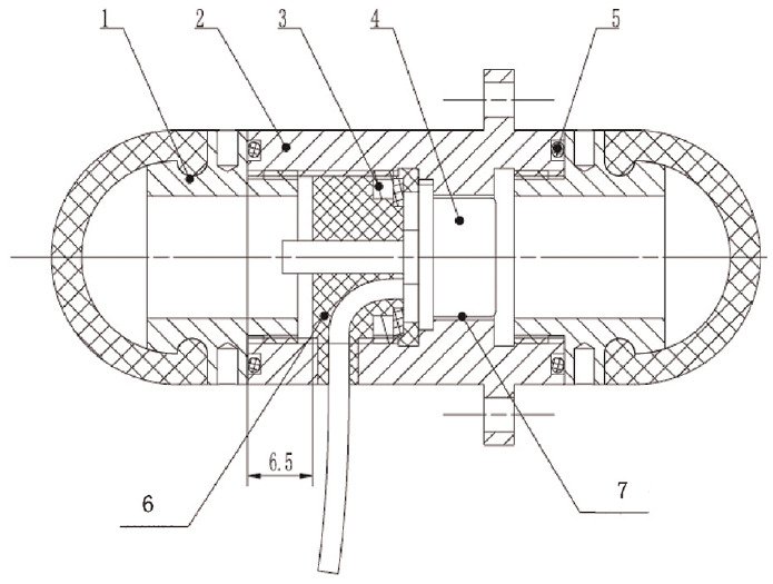
The diagram of the underwater tactile force sensor assembly. (1. Flexible contact; 2. Sensor shell; 3. Snap ring; 4. Sensor core; 5. O-shaped sealing ring; 6. Epoxy Resin AB glue; 7. Glue filling cavity).
The similar with the sensor principle in Figure 2, it can be seen from Figure 4 that the force sensor is mainly composed of the sensor core, the flexible contact, the stainless steel shell, snap rings, the Poly Tetra Fluoroethylene (PTFE) pad and other parts. The force sensor is composed of upper and lower flexible contacts and a stainless-steel shell in the middle part. The hemispherical flexible part of the flexible contact is made of a mixture of silica gel and nitrile rubber (NBR), which can maintain the hemispherical shape and has software material to easily convert into internal silicone oil pressure through deformation. The hemispherical flexible part of the flexible contact has stable insulation properties and corrosion resistance. In order to facilitate the installation and connection of the flexible contact to the stainless-steel shell, the hemispherical flexible part is firmly bonded to the cylindrical stainless steel metal part through a vulcanization process, which has a good sealing effect. The cylindrical stainless steel metal part is assembled and connected with the stainless-steel shell in the middle of the sensor through the thread. The sensor core is installed in the shell of the tactile force sensor, and is firmly fixed by a small inner diameter on one side, and the sensor core is fixed and compacted by a snap ring on the other side. In order to prevent the compaction process from damaging the small circuit board of the sensor core, a PTFE insulating pad is used for isolation and protection. The sensor core has been designed as a differential pressure structure. The upper side is essentially the bottom of the silicon cup that can directly sense the hydraulic pressure of the silicon oil; the lower side can guide the silicon oil to the other side of the silicon cup through a metal tube to form a differential pressure structure.
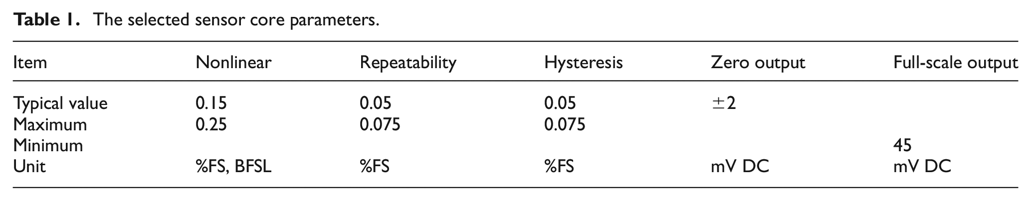
The sensor core measurement circuit is essentially a Wheatstone bridge. Two power supply wires and two signal wires are guided to the outside of the sensor through holes in the force sensor shell. The epoxy resin AB glue is used to pour and seal the gaps inside the force sensor shell to fix the sensor core conduits and wires. The upper end of the sensor core is also poured with epoxy resin AB glue to ensure that there are two independent cavities inside the force sensor to prepare to the silicon oil filled. The prototype of the tactile force sensor and some parts are shown in Figure 5. The inside of the flexible contact is hollow, and the inside of the flexible contact and the sensor shell are filled with silicone oil. Two separate containers filled with silicone oil will cause interference from bubbles due to insufficient filling. Or, during the installation process, the silicone oil cannot be discharged to produce a pressure signal, which causes a problem of zero drift of the force sensor output. In the actual installation process, the assembly process of the flexible contact and the sensor housing is completed in a silicone oil environment. This installation method ensures that the silicone oil can be filled and the bubble problem is avoided. The thread of the flexible contact and the thread of the sensor housing have a large tolerance, so when the flexible contact is rotated and tightened, the excess silicone oil will be discharged out of the housing, and finally the sealing ring after tightening is ensured. The selected sensor core parameters are shown at Table 1. It can be seen from Table 1 that the typical value of nonlinear and repeatability are 0.15% and 0.05%, the sensor core having a linear output capacity can be concluded.
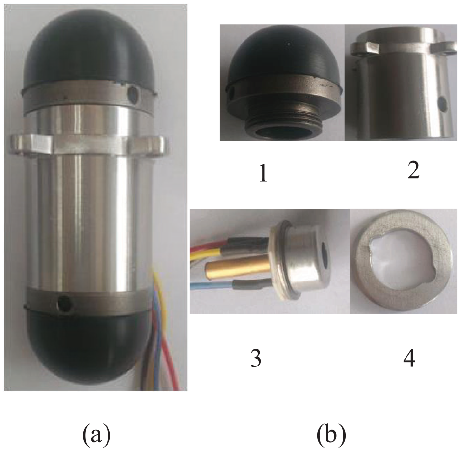
The prototype and part components: (a) the overall sensor picture and (b) part components (1. Flexible contact; 2. Sensor shell; 3. Sensor core; 4. Snap ring).
The selected sensor core parameters.
Preparation of the sensor experiment
For the designed underwater tactile force sensor, in order to verify its output performance and achieve sensor calibration, the experiment tests are required. The test process is to load the set known tactile force to verify the sensor signal output characteristics. In the non-underwater environment, the tactile force test can be directly loaded with the weight or the load cell. However, the underwater tactile force sensor is easily affected by the water environment, and it is difficult to load the tactile force in the water environment. The underwater tactile force sensor experiment is mainly to test the relationship between the sensor’s zero output and the water depth, and the output characteristics of the sensor under the influence of water depth and water temperature.
Experiment equipment setup
The stable placement of the tactile force sensor is essential for achieving reliable and accurate measurements of standard force signals during testing. However, due to the contact-based tactile force perception mechanism between the hemispherical flexible contact and external force, it is challenging to maintain a stable placement of the sensor, especially in underwater environments where it can be difficult to load a certain standard force signal under the influence of water pressure. The water environment cannot provide a certain temperature for the designed sensor. The ideal underwater tactile force sensor calibration equipment should be in the form of a thermostat container, which can provide a certain adjustable underwater pressure and a standard tactile force loading. What is more, it should have the function of providing the water with certain temperature. It is ensured that the underwater tactile force sensor can be calibrated in the laboratory environment. During the experimental testing and calibration process, it is possible to simulate the underwater environment at different water depths by applying corresponding pressures. However, currently, there is no available calibration equipment on the market for the underwater tactile force sensor. Even if such equipment becomes available in the future, it is expected to be expensive. Due to the limitation of the conditions, and preliminary verification of the performance of underwater tactile force measurement of the designed tactile force sensor, the measurement is realized through the calibration equipment whose structure is shown in Figure 6.
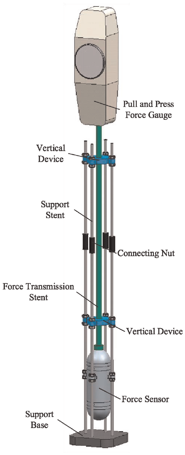
Force loading equipment.
It can be seen from Figure 6 that it is a simple device which called calibration equipment for the realizing underwater tactile force loading. The four screw holes on the sensor are equipped with four support stents to realize the fixed installation of the sensor, and the four support stents are fixed on the support base. The upper end of the sensor and the upper end of the support stent are equipped with a vertical device to realize the vertical of the force application rod, and ensure the vertical contact between the force application rod and the tactile force sensor. The force is achieved to load on the sensor contact by the pull and press force gauge through the force transmission stent, and the force transmission stent which parallels the four support stents is contacted to the force sensor vertically by the vertical device. The four support stents and the force transmission stent both have threads on the surface, and the corresponding extension can be realized by the connecting nut to ensure the realization of different water depth measurement. The supporting base realizes the supporting and fixing function of the whole device. This design method ensures that when the operator is located outside the water surface, the force can be applied to the flexible contact of the sensor with adjustable water depth environment.
In the test process, four stents are needed to bring the tactile force sensor to a certain water depth, and the force can be transmitted to the underwater force sensor by the force transmission stent through the vertical device, thus avoiding the inconvenience that the operator needs to load the standard force signal in the underwater environment. The four stents can be extended by using a connecting nut, and the gravity of the force transmission stent can be measured using a pull and push force gauge. Similarly, the force applied to the tactile force sensor can also be measured using a pull and push force gauge, thereby achieving the loading of a standard tactile force signal on the underwater sensor. This design ensures that the operator is located outside the water surface and can load the force onto the flexible head of the sensor in an adjustable water depth environment.
During the experiment, the water depth environment can be produced by changing the pressure of the water through outer mechanical device, but there is no appropriate equipment purchased on the market at present. Because of this limitation, a cylindrical sink which can provide a constant temperature water and a constant water pressure is essential to design. As shown in Figure 7, there is a metal round pipe with a faucet on the base. The metal round pipe and the base are connected by the thread, and the pipe can be prolonged by threaded connection. A certain underwater environment is achieved when a certain temperature of water injected in the cylindrical sink. The cylindrical sink can stand and be fixed upright with the support of the building. The calibration equipment with the underwater force fixed on the supporting base is taken in the cylindrical sink, and the stranded force is loaded on the top surface of the flexible contact to achieve the sensor output with certain depth and certain temperature.
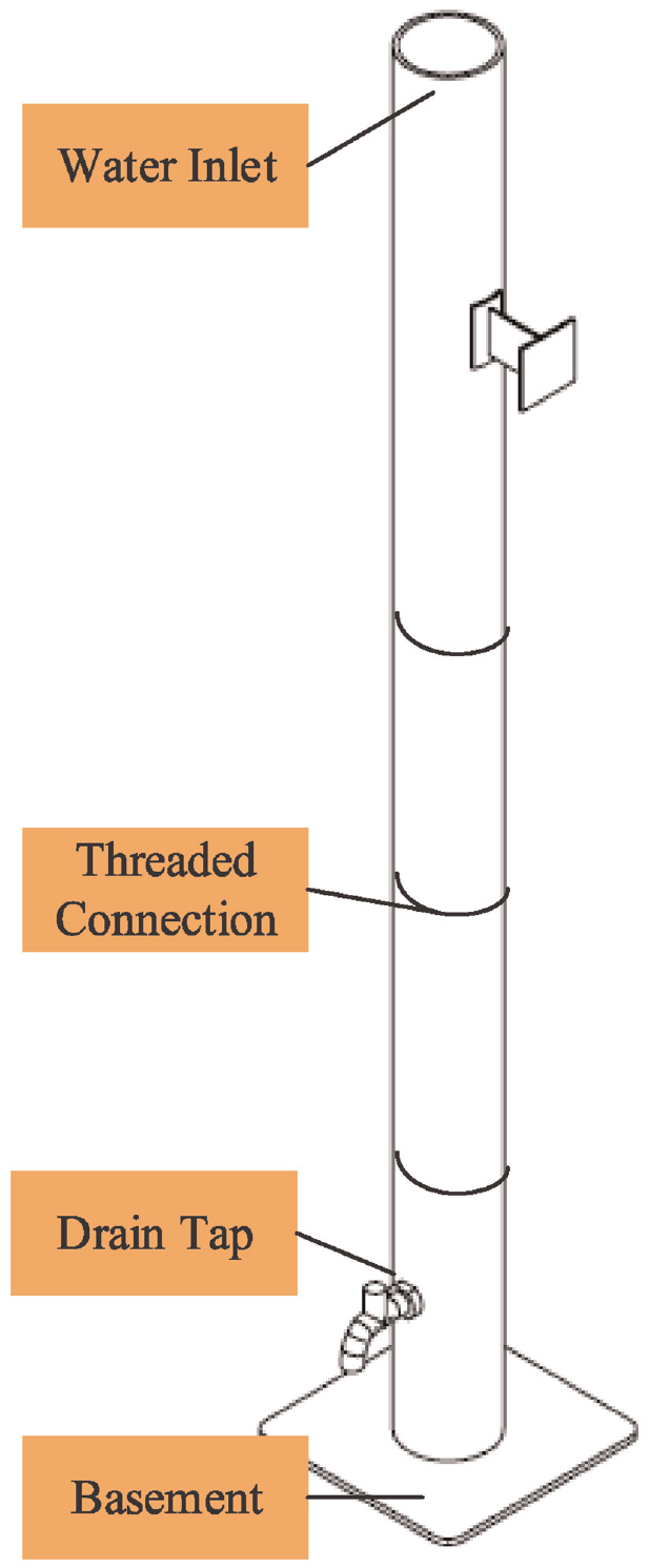
Water environment supply equipment.
Circuit system
To achieve a standard tactile force signal output through BP neural network data regression, a hardware circuit system has been designed in this study. The silicon piezoresistive sensor used in the system is susceptible to temperature drift due to the temperature effect, and previous experimental results have shown that the tactile force signal output of the sensor core cannot completely eliminate the influence of water pressure, which may be attributed to a manufacturing process problem. To compensate for the temperature and water pressure signals using the BP neural algorithm, it is necessary to collect the temperature and water pressure signals as training data for the BP neural network. The sensor core output signal is collected under a known water temperature and water depth environment, and the loading force is applied in a regular sequence to ensure that the BP neural network has a wide range, strong robust performance, and local generalization ability. The known water temperature and water depth signal is collected as the training data for the BP neural network. The circuit system diagram of the underwater tactile force sensor is shown in Figure 8.
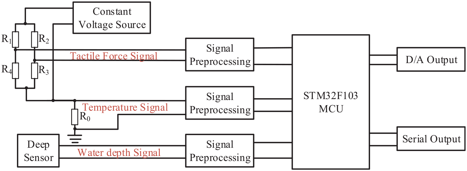
The schematic diagram of the sensor circuit system.
As illustrated in Figure 8, the Wheatstone bridge in the tactile force sensor core is powered by a constant voltage source, and the bridge outputs millivolt-level tactile force voltage signals for tactile force signal collection. However, since the four resistors in the Wheatstone bridge are composed of semiconductor materials, they are sensitive to temperature signals. Therefore, the four resistors can be considered equivalent to a temperature-sensitive resistor, and the temperature signal can be measured by measuring the voltage across
The realization process of BP neural network in STM32 microcontroller involves an online calibration process and a trained network data regression process. The use of BP neural network for data regression requires offline training of the constructed BP neural network. 37 The training process is conducted on a computer, which is connected to the STM32 microcontroller through serial communication. In the online calibration process, the collected tactile force signal, temperature signal, and depth signal are sent by the STM32 microcontroller to the computer. At the same time the computer software receives the three kinds of signals and adds the actual tactile force value to form a set of data. This calibration data is then used to establish a BP neural network for training.
The trained BP neural network is tested using test samples to verify its data regression performance. If the approximation error is within a set range, the BP neural network is considered well trained and can be used for data regression. The well-trained BP neural network weights, thresholds, and other data are sent to the STM32 microcontroller via serial communication according to a specific protocol, completing the online calibration process. After completing the online calibration, the STM32 microcontroller program is transferred to the trained network data regression process. This process involves real-time collection of tactile force signals, temperature signals, and depth signals, and the output of real tactile force values is achieved through trained network function data regression.
BP neural network data regression
The equipment required for calibration experimental sample collection is: the designed underwater tactile force measurement sensor, depth sensor, signal measurement and control circuit board, standard force loading force gauge, water container, test and calibration device, the computer and so on. The underwater tactile force sensor is positioned within the calibration device, which is situated inside a water container. A depth sensor is installed on the calibration device, and the power supply line extends to the water surface to link to the signal measurement and control circuit board. The signal circuit board is then connected to the testing computer through serial communication. In the process of collecting training samples and testing samples of the neural network, the microcontroller completes the power-on initialization, and the timer interrupts to realize the A/D conversion measurement of temperature and tactile force signals. The deep signal collection is realized through serial communication, and the three channels are collected. The data is sent to the test computer through serial communication, and three data of tactile force, temperature and depth are recorded on the test computer.
The zero point output measurement with different water depth
In order to ensure the reliability and stability of the sensor, the zero-point test of the sensor under different water depths is first carried out. We place the sensor under different water depths of 0–6 m, and when the sensor does not apply tactile force, add 7.4 V voltage power supply to measure the output of the Wheatstone bridge circuit. The zero-point output voltage diagram of the sensor at different depth is shown in Figure 9. It can be concluded from Figure 9 that there is an approximately linear relationship between the sensor zero-point output and the water depth. The sensor zero output value changes from 83 mV at depth 0 m to 89 mV at depth 6 m.
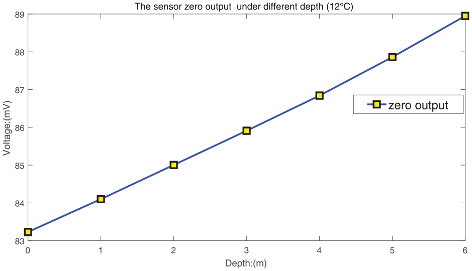
The sensor zero point output with different water depth.
Although the ideal condition differential pressure structure eliminates the influence of water pressure, it is found in actual tests that the influence of water pressure is not completely eliminated, and a phenomenon of fixed drift is formed. The main reason is the processing technology and installation problems. It is not possible to guarantee the same volume of filled silicone oil on the upper and lower sides. As the external water pressure changes, the pressure of the silicone oil on the upper and lower sides of the bottom of the silicon cup changes.
The sensor output under water depth
After the zero-point experiment, it is necessary to load different known tactile force at a constant temperature water environment to realize the sensor output experiment. Place the underwater tactile force sensor in a water depth of 0, 2, 4, and 6 m, and load a known force in each water depth environment. Take a tactile force value every 3 N between 0 and 30 N, record the sensor output and plot the curve as shown in Figure 10. According to Figures 9 and 10, it can be concluded that the output of the tactile force sensor under a certain water depth has linear characteristics, and it has the features that the output sensitivity is high and the output nonlinearity is small. Because of the influence of water pressure, the zero-output drift of the underwater tactile force sensor is caused, which causes the sensor output to drift regularly when the same standard force is loaded at different water depth. The sensor output curve at each depth is approximately parallel.
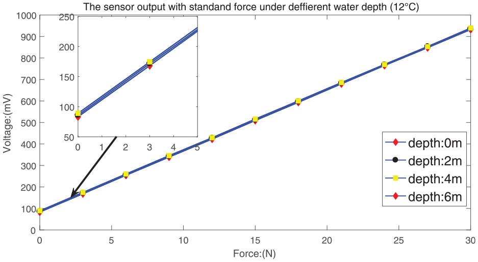
The sensor output with different water depth.
The sensor output under temperature influence
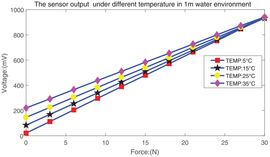
The manufacturing processes used to produce the four force sensitive units in the silicon cup sensor core, such as ion injection or impurity diffusion, make it impossible to guarantee that each unit has the exact same shape, size, and temperature coefficient. As a result, the output of the silicon cup underwater tactile sensor may exhibit temperature drift. In order to ensure the reliability and output stability of the underwater tactile force sensor in the temperature range of
The sensor output with different water temperature.
It can be concluded from Figure 11 that the designed force sensor has the output with temperature drift problem. The maximum temperature drift takes place at the zero point output, and the force sensor output is shifted from 21 mV at water temperature
BP neural network data regression
The BP neural network does not need to determine the mathematical equations of the mapping relationship between the input and output in advance. It only learns a certain rule through its own training, and obtains the result that is closest to the expected output value when the input value is given. 38 The BP neural network data regression performance is better than the least square method and polynomial data regression algorithm. 39 As can be seen from Figures 10 and 11 above, the output of the underwater tactile force sensor is not only determined by the loaded tactile force, but also affected by the water pressure and the water temperature, which forms the problem of cross sensitivity. The output zero drifts from 21 mV at the depth of 0 m to 220 mV at the depth of 6 m, and 935 mV at the depth of 0 m to 941 mV at the depth of 6 m when loaded at full scale. At different temperature point, the tactile force output under the same water depth conditions drifts regularly, so the temperature and depth data compensation are to be carried out with BP neural network algorithm to achieve the real force value output.
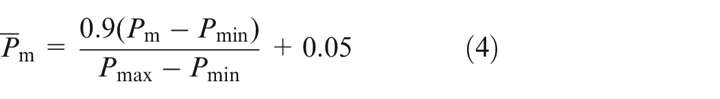
In order to improve the parameter adjustment of the BP neural network and enhance its convergence speed, it is essential to normalize the original measurement data. This involves normalizing the input and output data using equations such as equations (3) and (4).
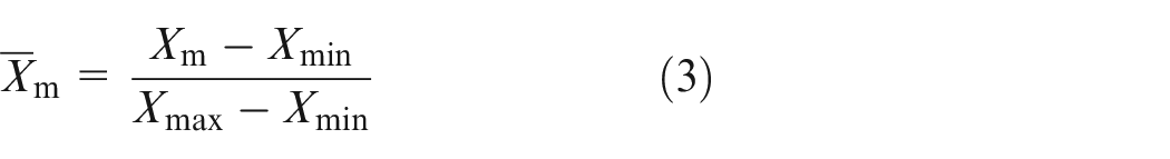
where

where
The BP neural network data regression algorithm is employed to realize the compensation for the cross sensitivity caused by water temperature and water depth. A multi-hidden layer neural network structure is established by using the tactile force measurement value, temperature measurement value, and water depth measurement value signals as the input of the BP neural network, and the standard tactile force output as the one-dimensional variable output. 40 The offline training of reasoning ability realizes the nonlinear mapping from input to output signal, and obtains the data regression function based on BP neural network weight and threshold. The schematic diagram of the built BP neural network is shown in Figure 12. The training of BP neural network adopts the Levenberg-Marquardt (LM) algorithm with variable step size and momentum factor, which can speed up the network training speed and prevent the network from being locally limited to the minimum points.
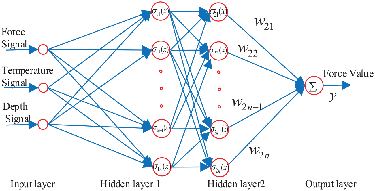
The Schematic diagram of the built BP neural network.
Open the neural network toolbox in Matlab and create a four-layer network. The first layer is the input layer with three neurons representing the sensor core output signal, the temperature signal and the water depth signal. The output signal of the sensor core means the voltage form signal output by the sensor core, which is the voltage signal that reacts to the tactile force information before data fitting. It is essentially the silicone oil pressure signal inside the designed force sensor. The input layer is the normalized value of the three variables, at the same time, the output layer is mapped to the normalized value of the loaded standard force. The first hidden layer, the second hidden layer and the output layer has respectively 10 neurons, eight neurons, and one neuron, and the activation functions of the input layer, hidden layer, and output layer are all tansig function.
There are three dimensions of BP neural network training sample input data, namely, representing the tactile force sensor signal, the temperature measurement signal, and the depth sensor signal. Among them, take the tactile force value every 3 N between 0 N and 30 N as the force point, and take the temperature value every
Set the training parameters for the created BP neural network. The approximation error is
In order to further verify the effectiveness of the well-trained BP neural network for temperature and depth compensation and to test the data regression ability, the force sensor are used to verify the trained neural network performance. According to the output characteristics of the sensor, under the same tactile conditions, under different temperature and strong water pressure conditions, the output force after BP network processing will no longer change. The output value of the neural network is de-normalized and the regression value is obtained. The weights and thresholds of the well-trained BP neural network is transplanted to the STM32 microcontroller to achieve the tactile force signal data regression. The experiment is divided into two step. Firstly the temperature is kept constant, and the same tactile force is loaded under different water depth condition to test the sensor data regression output, and the sensor regression output data is shown in Figure 13. For the second time, keeping the water depth constant, loading the same tactile force under different water temperature conditions to test the sensor data regression output, and the sensor regression output data is shown in Figure 14.
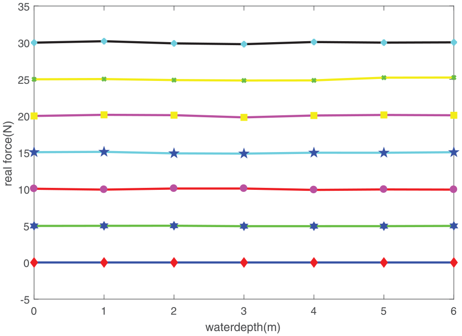
The sensor output under BP neural network processed with different water depth.
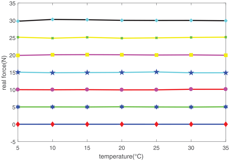
The sensor output under BP neural network processed with different water temperature.
It can be seen from Figures 13 and 14 that when the same force is loaded at the same temperature point and the water depth changes, the output value of the tactile force signal remains constant after the BP neural network data regression. When the same force is loaded at the same water depth while the water temperature changes, the output value of the tactile force value still remains constant after regression of BP neural network data. When the sensor is loaded with the same tactile force, its output value remains basically constant under different water depths and different temperature conditions. The BP neural network data regression algorithm eliminates the influence of water depth and water temperature on the output of the tactile force sensor, and it has a good data regression effect. The output accuracy of the tactile force sensor is 5% after fitting the BP neural network data.
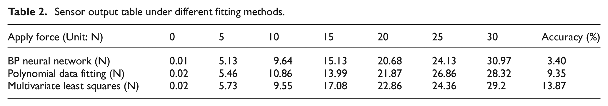
In order to verify the advanced performance of BP neural network data fitting, the different fitting functions, including the multivariate least squares 41 and polynomial data fitting method, 42 are used to the underwater tactile data fitting to achieve a comparison with the BP neural network.
The output of different water depth, different temperature, and tactile force signals is employed as the input date of the fitting function. The loaded tactile force value is used as the output data to calibrate the fitting function. The same test sample is utilized to test the performance of different calibrated fitting functions. Under the condition of tactile force applying with the range of 0–30 N, the output force value of different calibrated fitting functions are indicated in Table 2. It can be concluded that the output with BP neural network calibration algorithm has high output accuracy, good fitting linearity, and good output stability.
Sensor output table under different fitting methods.
Discussion
The designed tactile force sensor has a length of 31.5 mm and a shell radius of 25 mm, which achieves a linear relationship between the contact force and the sensor output when the hemispherical flexible contact is in contact with the outside. It can be seen from Figure 4 that the selected silicon cup core of the sensor has a shell, and the tactile force sensor also has a shell. The dual shell structure limits the reduction of the sensor volume. Therefore, the next step of research and design can remove the shell of the sensor core, and directly install the sensor core with the shell removed into the shell of the tactile force sensor. It can even be directly made into a manipulator finger joint to further reduce the volume of the underwater tactile force sensor to achieve the characteristics of a high-density array type tactile force sensor. Due to the rudimentary equipment for sensor measurement and calibration, only data measurement and calibration experiment at a depth of 6 m have been implemented, and it cannot be extended to deeper underwater environments. Therefore, the underwater tactile force sensor calibration equipment that provides a certain water pressure, a certain water temperature and can achieve array calibration is of great significance to the development of the force sensor.
The designed tactile force sensor is easy to install, and the silicon cup-type sensitive core has high output accuracy, which avoids the construction of a Wheatstone bridge and has the standard signal output. The designed tactile force sensor is better than the strain gauge type sensor. 14 And it reduces the complicated circuit system and it is easy to calibrate, 16 which is better than the optical fiber tactile force sensor. 17 The experiment and calibration process of the underwater tactile force sensor is realized under the static pressure of water. The flexible contact has a certain thickness and waterproof insulation characteristics, and it has a certain robust performance against water flow interference which is anti-corrosive feature in combination with a stainless-steel shell. The signal processing of the corresponding sensor and the circuit board based on STM32 calibration are located outside the sensor to realize the calibration process in a non-underwater environment. In the future, the circuit board and micro-controller which is installed inside the sensor to reduce the volume of the sensor to realize the processed standard force signal output is also a research direction.
Conclusion
This paper presents a solution to the cross-sensitivity issue in underwater tactile force measurement, which is often impacted by changes in water pressure and temperature. To address this problem, we designed a new differential pressure structure MEMS tactile force sensor and used a BP neural network data regression algorithm to calibrate the sensor. The designed tactile force sensor measures external tactile force information through two flexible contact on the upper and lower side. The upper flexible contact of the tactile force sensor is capable of sensing both water pressure and tactile force. Meanwhile, the lower flexible contacts are used to measure only water pressure. The MEMS force sensitive elements are connected to the upper and lower ends of the sensor through an internal silicone oil guide, and the tactile signal measurement is achieved by vector overlay.
The structure and manufacture technology of the sensor were introduced, and the BP neural network data regression algorithm was designed for the cross sensitivity of the tactile force sensor output caused by water temperature and water static pressure. The four-layer BP neural network was established and offline trained with the collected data of water temperature, water depth and force voltage signal as input data and desired data as output data, achieving to real tactile data regression value output with high accuracy. Experimental results demonstrate that the differential pressure structure effectively eliminates the influence of water static pressure, while the BP neural network data regression algorithm enables the output of real tactile force signals. These findings have significant implications for the intelligent operation of underwater dexterous hands. Moreover, the sensor accuracy was determined to be 5%. The designed tactile force sensor realizes the real tactile force output through data regression, eliminates the influence of water temperature and pressure on the tactile force output, and is of great significance to the intelligent operation of underwater robots.
In addition, the new measurement methods, new materials, and new processes are all directions for the development of underwater tactile force measurement technology. During the calibration of underwater tactile sensors, the water pressure environment supply, the temperature environment supply, and the loading of the tactile force require further research. The output form of the tactile value after calibration can be further enriched. For example, it can realize industrial Ethernet force output, WIFI mode output, and the form output based on the CAN bus. It is worth digital output to achieve further implementation direction.
Footnotes
Acknowledgements
The authors are grateful to the editor and anonymous reviewers for their valuable suggestions that helped in improving the initial version of the manuscript. The authors would like to express their appreciation to the referees for their helpful comments and suggestions.
Declaration of conflicting interests
The author(s) declared no potential conflicts of interest with respect to the research, authorship, and/or publication of this article.
Funding
The author(s) disclosed receipt of the following financial support for the research, authorship, and/or publication of this article: This work was supported by National Natural Science Foundation of China (NSFC) (No.52177039), Natural Science Foundation of Henan (No. 232300421152), Henan Province Scientific and Technological Project of China (Nos. 232102240036, 232102220030, 232102240103, and 232102211004) and The Basic Research Business Fund Special Project of Henan Polytechnic University (No. NSFRF230434).