
Abstract
In searching for the optimal control strategy of sub-module capacitance voltage equalization of Modular Multilevel Converter (MMC), the most important issue is how to address the significant increase in computing time of the controller, switching frequency of the sub-module, device switching loss and MMC fault rate led by the increase in the number of sub-modules of the upper/lower bridge arm of the MMC. Therefore, this paper proposes a control strategy based on the retaining factor method + improved quick sort, namely, an improved quick sort algorithm is used to sort the sub-module capacitance voltages to reduce the amount of computation of the MMC controller; at the same time, a retaining factor is introduced to participate in the improved quick sort to significantly reduce the switching frequency of the sub-module. MMC of large ship grid-connected photovoltaic power system is taken as a research object in this paper, a 31-level MMC model is built in Matlab/Simulink. Simulation results verify that the improved quick sort has a good rapidity compared to the algorithms of bubble sort, quick sort, bidirectional bubble sort, and improved merge sort, that the retention factor method has a good frequency reduction effect, and that the proposed retention factor + improved quick sort can provide a good performance compared to improved quick sort and retention factor + improved merge sort under conditions of the normal operation and introducing disturbance.
Keywords
Introduction
In recent years, Modular Multilevel Converter (MMC) has been widely used in the field of medium and high voltage due to its advantages of modular design, good output waveform quality, low switching frequency and strong fault handling capability. 1 MMC mainly adopts Nearest Level Modulation (NLM) technology, which greatly reduces its switching loss. At the same time the modular design of MMC makes it good expandability and greatly reduces the manufacturing difficulty. Therefore, MMC has unparalleled engineering advantages in enhancement of voltage level and transmission capacity, and become the mainstream choice for converters in VSC-HVDC systems. 2 MMC sub-module capacitance voltage equalization is a premise for its stable operation. The fluctuation of the sub-module capacitance voltage causes uneven energy distribution and distortion of the output waveform between the sub-module, which requires voltage equalization control of the MMC sub-module. 3
At present, the main MMC sub-module capacitance voltage sort algorithms are prime factor decomposition method, 4 shell sort method, 5 bubbling method, 6 and hybrid sort method. Literature7,8 proposed a quick selection sorting algorithm, which rapidly determines the position of the kth statistic in the voltage sequence in an iterative manner and uses this position as a dividing line for group sorting; this method reduces the system workload, but does not optimize the switching frequency of submodules. The literature9,10 reduces the workload of the system respectively by dynamic hierarchical sorting and parity parallel sorting, but the large number of indexing and calling instructions places higher demands on the hardware. The literature11,12 adopted the principle of algorithmic combination, using two sorting algorithms to perform mixed sorting for submodule capacitance voltage sequences, which reduces the number of elements to be compared and without changing the sorting results, but the effect on frequency reduction is not obvious. The literature13,14 reduces the switching losses and voltage deviations of the submodule respectively by controlling the dynamic threshold, the difference between the submodule voltage and its average value, but the sorting process of the submodule capacitance voltage is not optimized. The quality of MMC output voltage waveform in literature15–17 is closely related to the selection of retention factor, Modulation index and MPC input value, but the selection rules of optimal value are not described. The literature18,19 introduced improved quick sort algorithm and improved bucket sort algorithm for capacitance voltage equalization control, meanwhile the sub-module capacitance voltage sequence is sorted respectively in blocks and buckets, which reduces the amount of sorting to improve the computational efficiency, but the system still has excessive switching frequency.
The analysis conducted above highlights two primary issues with the MMC submodule capacitance voltage equalization control. These issues pertain to the sorting time and submodule switching frequency, and can be addressed by reducing the sorting time and decreasing the switching frequency.
By reducing the amount of sequencing operations, the submodule voltage equalization speed can be improved. Reducing the switching frequency of the submodules avoids frequent switching of devices and small changes in capacitance voltage, which can reduce the switching losses of the system and extend the life of the devices. 20
Therefore, this paper proposes a control strategy that combines the retention factor method with an improved quick sorting algorithm, and the main contributions are outlined below:
1. Enhancing the traditional quick sort method, enabling it to sort submodule capacitance voltages with only half the number of comparisons required by the traditional quick sort algorithm. This reduces the computation requirements of the control system and improves the response speed.
2. Incorporating the retention factor method into the improved quick sorting process, which increases the likelihood that submodules invested in the first cycle will remain engaged in the second cycle. This reduces the submodule switching frequency, leading to improved efficiency and reduced wear and tear on the system.
3. Designing and implementing the improved quick sort+retention factor method using MATLAB/Simulink, and building a 31-level modular multilevel converter simulation model. Various perturbation cases were simulated to verify the proposed control strategy’s feasibility, efficiency, and robustness.
Control for MMC
This paper chooses large ship photovoltaic power system as the application background, and the grid-connection structure diagram of ship photovoltaic power system is shown in Figure 1.
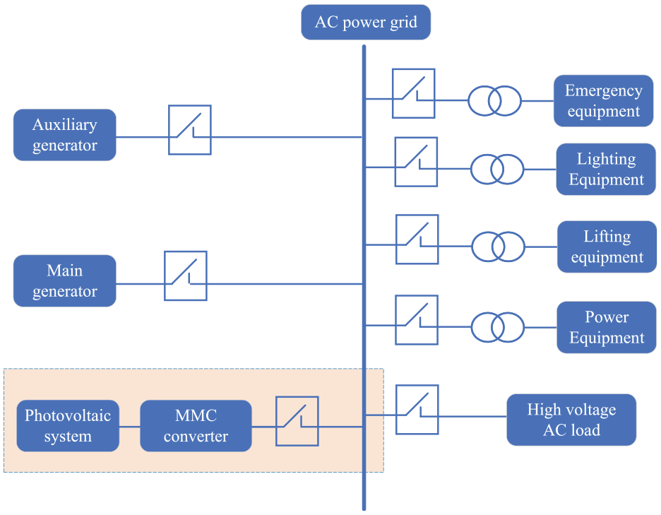
Grid connection structure diagram of ship photovoltaic power system.
In Figure 1, the DC power generated by the PV system is converted into AC power by the MMC, and the AC power is incorporated into the ship’s power grid, then supplied to various loads through the step-down transformer, or directly supplied to high-voltage AC loads.
Three-phase MMC is composed of six bridge arms with the same parameters and structure. The upper and lower bridge arms of each phase form a phase unit of MMC. Each bridge arm is composed of
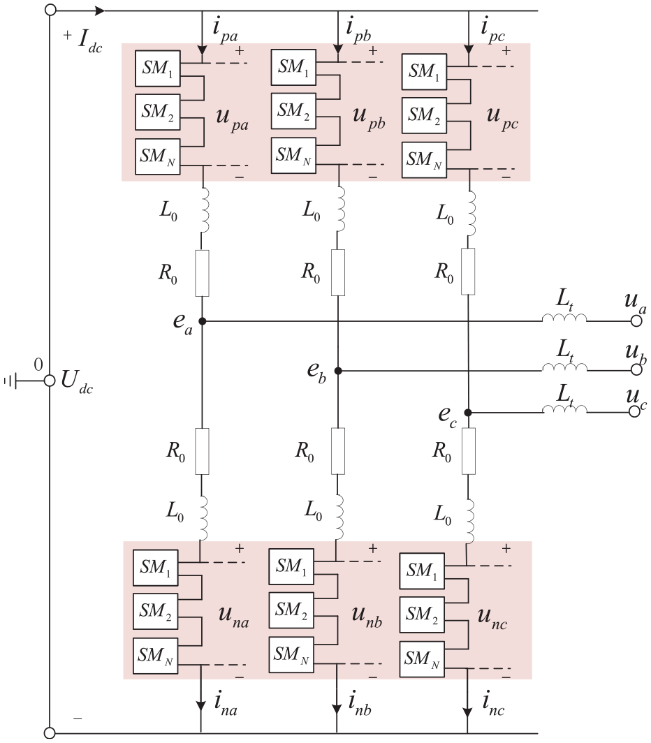
Three-phase MMC topology diagram.
The control diagram of the modular multilevel converter is depicted in Figure 3. The realization of MMC function consists of four parts: double closed-loop vector control, inter-phase circulating current suppression control, sub-module capacitance voltage equalization control, and modulation wave generation control. This paper mainly focuses on the research of the sub-module capacitance voltage equalization control.
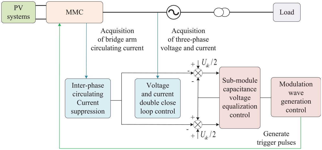
MMC control block diagram.
Equalization voltage control strategy based on improved quick sort
Conventional sub-module voltage equalization strategy
The traditional sub-module voltage equalization method determines which sub-modules need to be put into use according to the direction of the bridge arm current and the conduction number of the sub-modules. When the bridge arm current
The speed of the sub-module capacitance voltage sort algorithm determines the efficiency of the controller. When the number of sub-modules increases, if the sort algorithm is not good enough, which will increase the amount of computation of the controller and reduce the efficiency of the system. The analysis in introduction also shows that traditional sort algorithms such as bubble sort, quick sort, merge sort, Hill sort, and insert sort take up a lot of computer resources, resulting in lower system speed and heavier controller burden, therefore, some more effective sort algorithms such as bidirectional bubble sort, improved insert sort, improved merge sort, quick sort etc. have been proposed to improve the switching efficiency of sub-modular multilevel converters.
Principle and program design of quick sort algorithm
The quick sort algorithm was proposed by C.A.R. Hoare in 1962. The central idea of quick sort is to divide the original array into two parts by sorting, where any value in one part is greater than any value in the other part, and then repeat the above operation until the whole array is ordered.
According to the voltage level of the ship’s AC grid and sub-module number, assuming random sampling of 30 sub-module voltages are: [201, 202, 207, 209, 203, 204, 204.7,205, 210.1,210, 208, 196, 198.6, 191, 192, 197,199,193.9,193, 194, 195, 200, 198, 208.6, 206,205.2, 194.3, 196.5, 202.8, 206.5 V]. For easier illustration of the sub-module quick sort principle, 10 data are randomly selected and saved to a[10] = [206, 201, 202, 207, 209, 203, 204, 205, 210, 208]. The schematic diagram of quick sort is shown in Figure 4.
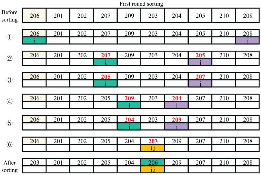
Schematic diagram of quick sort.
In first round sorting, the main steps are as follows:
First the pointer j is moved to the left (namely, j−−) until it finds a value less than 206 and stops. Then pointer i moves to the right (namely, i++) until it finds a value greater than 206 and stops. Finally pointer j points to value 205 and pointer i points to value 207. now exchange the values pointed to by pointers i and j. Next, simply repeat the above method to divide the original array into two groups using base value 206 as the dividing line.
Applying the quick sorting algorithm to the MMC submodule switching, the other issue that must be considered is which submodule corresponds to the smallest voltage value after sorting so that the trigger pulse signal can further be given. Therefore, the quick sorting algorithm procedure is designed as shown in Figure 5.
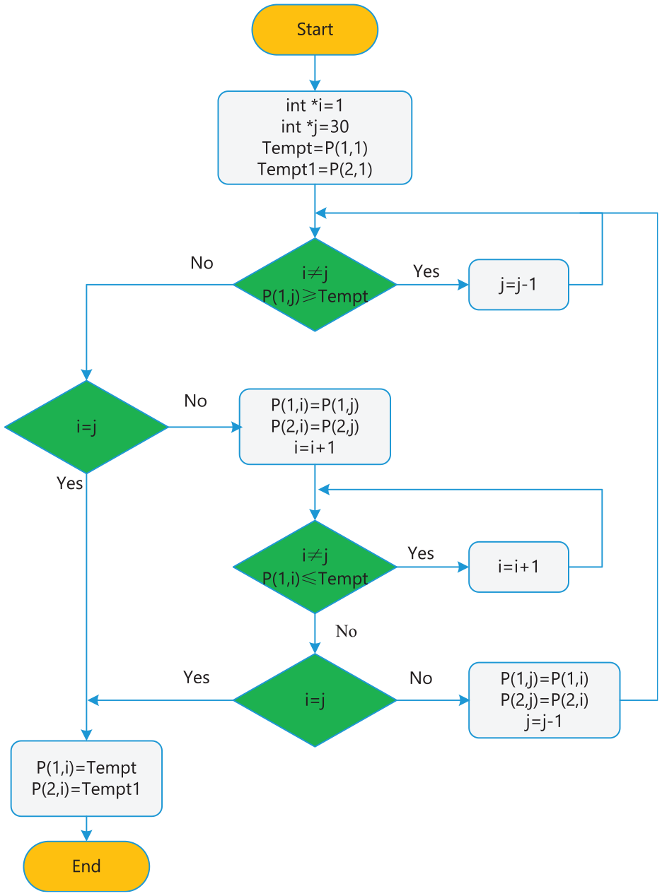
Quick sort flow chart.
In Figure 5, the first row of the matrix P is used to store the capacitance voltage values of the 30 submodules, and its second row stores the corresponding submodule serial numbers. The variables i and j are initially assigned values 1 and 30, which means that the pointers i and j point to the first and last positions of the matrix P, respectively. Tempt and Tempt1 are fixed variables to store the capacitance voltage value and serial number of the first sub-module. When the values of the first row of the P matrix are sorted according to the quick sorting principle, its second row always follows the first row to change (i.e. the columns of the matrix P exhibit overall changes).
Principle and program of improved quick sort algorithm
After the first round of quick sorting, the array is divided into two groups with the base value as the dividing line. The central idea of the improved quick sort algorithm is to compare the number of sub-modules that need to be conducted with the size of the arrays on both sides of the base value, and select the corresponding sub-module to give the trigger pulse signal according to the different bridge arm current directions.
The schematic diagram of the improved quick sort is shown in Figure 6, and the array in Figure 4 is still used as an example for a more intuitive illustration.
Schematic diagram of improved quick sort.
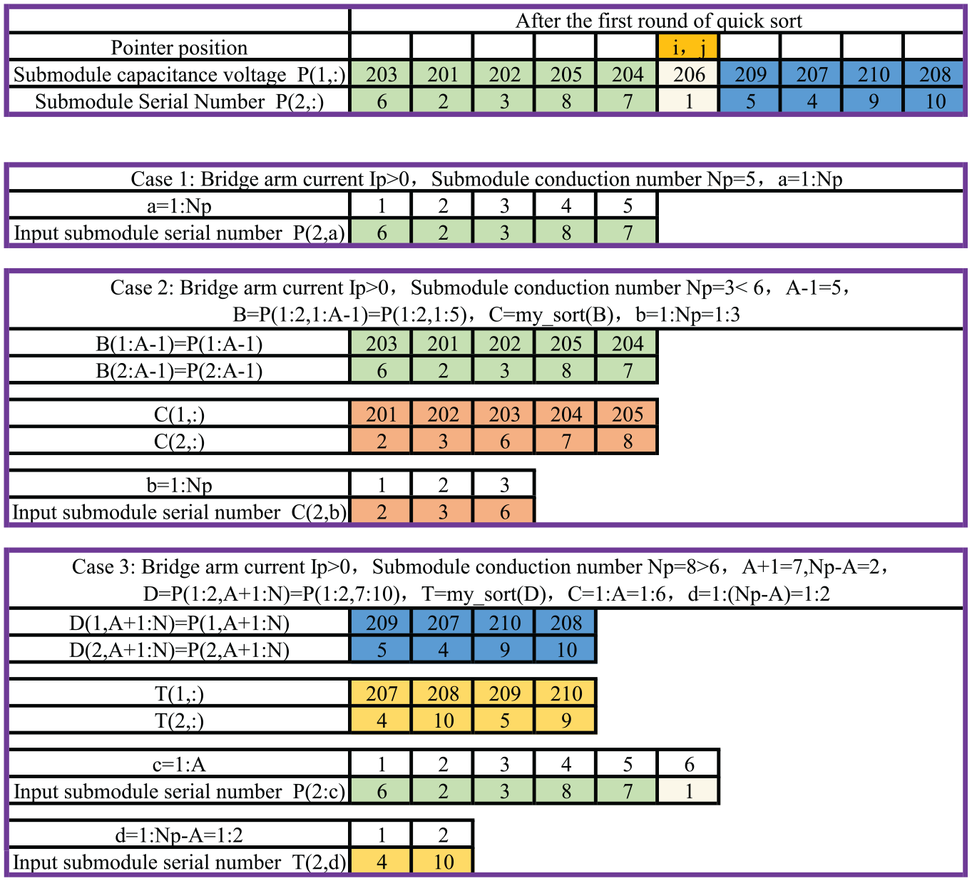
In Figure 6, after the first round of quick sorting, the base value 206 of the array is located at position
When case (i) occurs, the number of submodule conduction
By summarizing the above principles, the improved quick sort procedure can be obtained as shown in Figure 7. After the first round of quick sort, the base value by counting program returns the new address assigned to the fixed variable
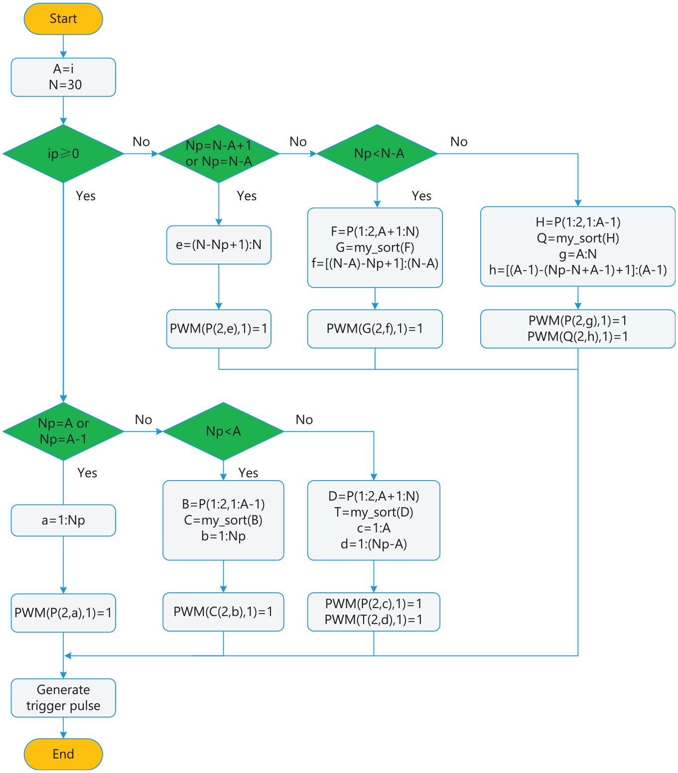
Improved quick sort flow chart.
Execution time comparison of sort algorithms
An array of random integer in [1, 1000] is used to verify the rapidity of the improved quick sort algorithm compared to the bubble sort algorithm, the quick sort algorithm, the bidirectional bubble method, the improved merge sort algorithm, 23 and the running time of each sort algorithm by using the timing function are obtained in Figure 8.
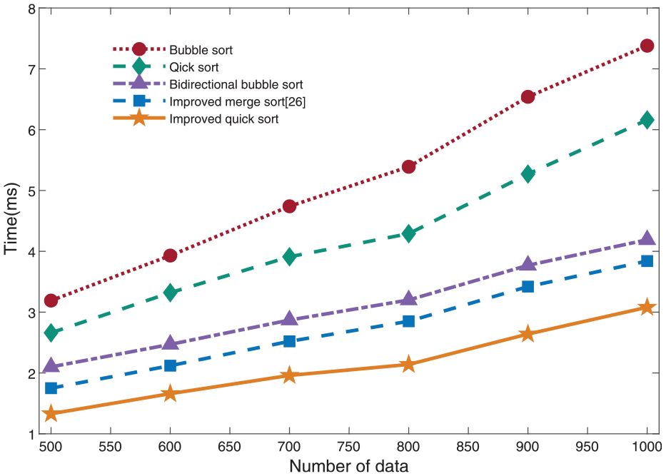
Running time of sort algorithms.
From Figure 8, it can be seen that compared with the bubble sort method, the quick sort method, the bidirectional bubble method and the improved merge sort algorithm, the improved quick sort method significantly reduces the sort time, and the more the number of elements in the array the more obvious the efficiency improvement, which verifies the efficiency of the improved quick sort algorithm.
Improved equalization voltage control strategy
In order to balance the control effect of capacitance voltage and device switching frequency, it is necessary to stabilize the capacitance voltage fluctuation in a suitable range on the one hand, and reduce the switching frequency of the device on the other hand. Therefore, the retention factor method is introduced to realize the frequency reduction optimization of the sorting algorithm.
Frequency reduction strategy
The principle of frequency reduction by the retention factor method is shown in Figure 9, in order to illustrate more intuitively, case one in Figure 6 is used as an example to expand the description. As can be seen in Figure 9, the serial numbers of the submodules put into the first control cycle are 6, 2, 3, 8, and 7, and the corresponding submodule voltages are 203, 201, 202, 205, and 204 V, respectively. It is assumed that the voltage of each submodule increases by 3 V after charging, that is, at the end of the first control cycle, the corresponding capacitance voltage values of each submodule are 206, 204, 205, 208, 207, 206, 209, 207, 210, 208 V. Assume that the second control cycle conditions remain the same, that is, the bridge arm current
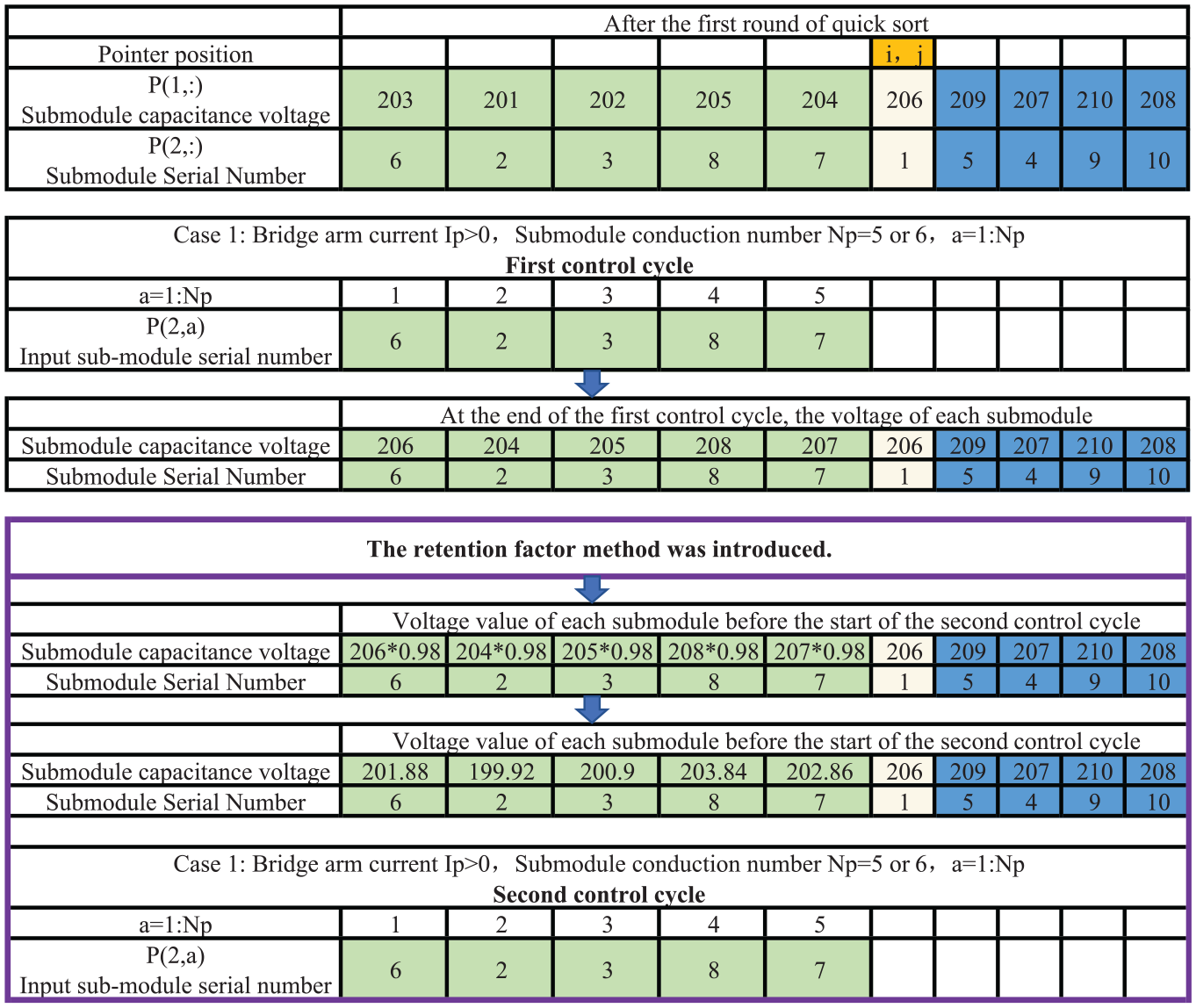
Retention factor method frequency reduction principle.
When the bridge arm current
When the bridge arm current
Retention factor method combined with improved quick sort
It is necessary to set the capacitance voltage threshold according to the requested capacitance voltage fluctuation rate of the sub-module which meets the requirement of system stability, namely, a judgment instruction is added before generating a new array by the retention factor method, which can guarantee that the capacitance voltage of the sub-module fluctuates within the specified range.
The specific process is shown in Figure 10, where
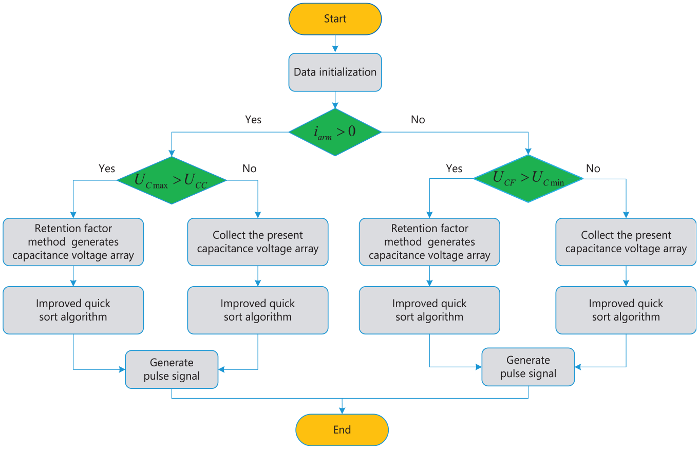
Combination of retention factor method and improved quick sort.
Simulation verification
Setting parameters
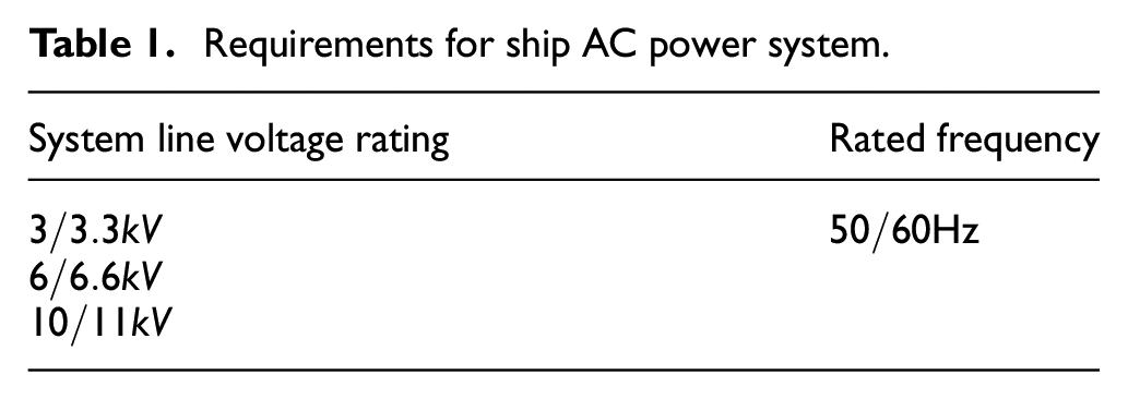
Referring to GB/T 13031-1991 requirements for ship AC power system with voltage 1–11 kV, 24 the voltage and frequency of the ship power system must conform to the regulations of Table 1.
Requirements for ship AC power system.
The MMC modulation ratio
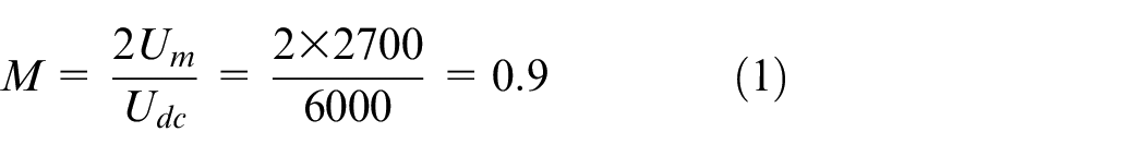
The rated value of ship AC power grid line voltage is 3.3 kV, thus the phase voltage amplitude is 2.7 kV. According to the MMC modulation ratio is 0.9, the DC side voltage of 6 kV is obtained. The number of sub-module is 30, therefore the rated sub-module capacitance voltage is 200 V. In order to reduce the fluctuation of sub-module capacitance voltage as much as possible, the fluctuation rate of sub-module capacitance voltage is set as 5%. The MMC output active power and reactive power are set as 3 and 1 MW, respectively. The specific setting parameters of the MMC converter are summarized in Table 2.
Setting parameters of MMC converter.
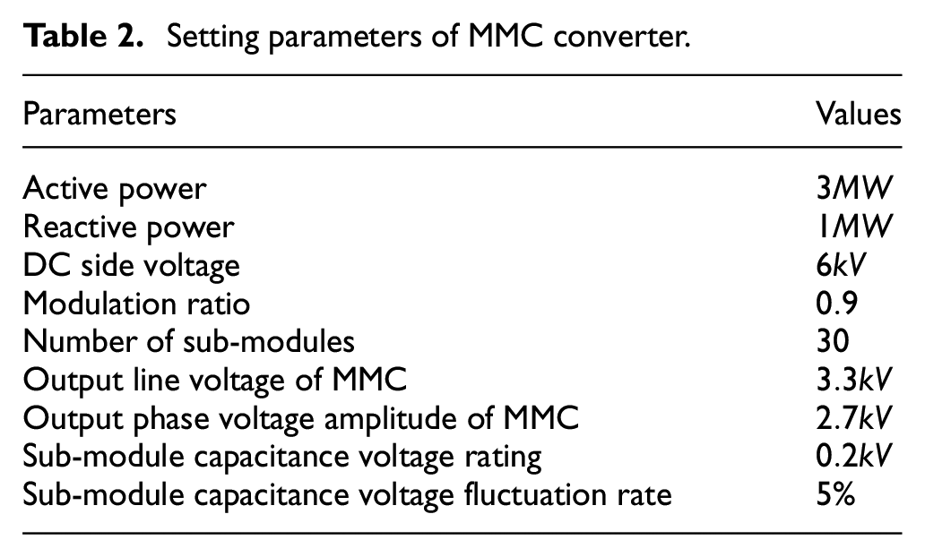
According to parameters in Table 2, the other parameters of MMC converter can be obtained as follows:
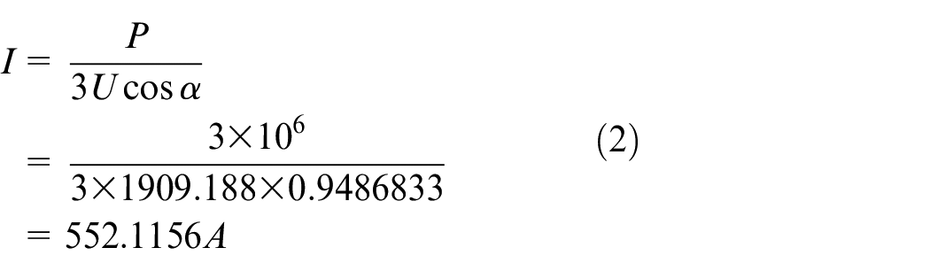
MMC phase current:
MMC phase current amplitude:

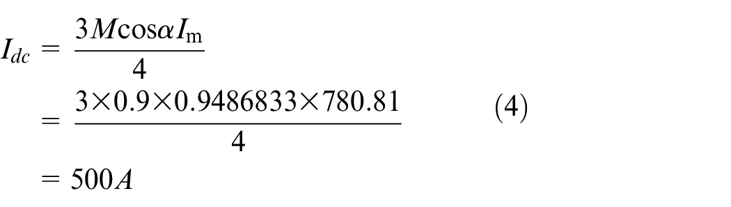
MMC DC side current:
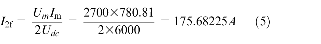
MMC Circulation Component Amplitude:
Filter inductance: The voltage drop on the inductor is within 5% of the rated phase voltage, inductance can be expressed by
Sub-module capacitance:
Bridge arm inductance:
In order to verify the effectiveness of the proposed strategy, a 31-level modular multilevel converter simulation model is built on the Matlab/Simulink platform.
Optimization effect of retention factor method
In order to verify the effect of the retention factor method, the changes of the sub-module switching frequency and capacitance voltage before and after the introduction of the retention factor method involved in the improved quick sort are compared. Figure 11(a) shows that the trigger pulse generate by only the improved quick sort, and Figure 11(b) shows that the trigger pulse generate by the retention factor+improved quick sort. The results indicate that the sub-module switching frequency is significantly reduced after the introduction of the retention factor. The peak capacitance voltage of the sub-module optimized by introducing the retention factor method is obtained in Figure 12, the results indicate that the peak capacitance voltage increases but still varies within the set threshold, and the fluctuation of the sub-module capacitance voltage is more stable and smoother.
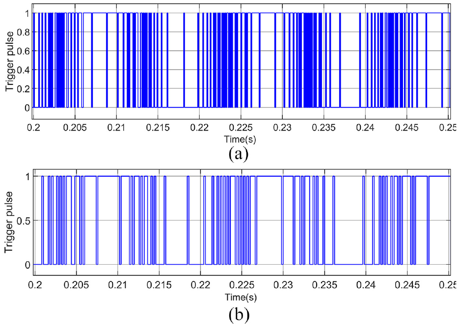
Trigger pulse comparison: (a) improved quick sort and (b) improved quick sort+retention factor.
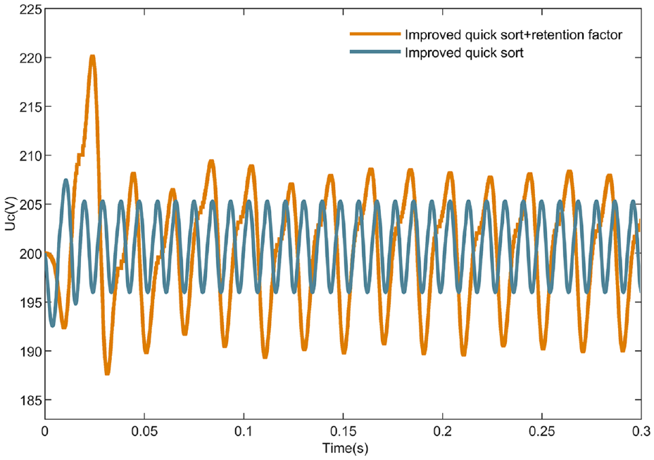
Sub-module capacitance voltage comparison.
Simulation results under different operation conditions
Scenario of without disturbance
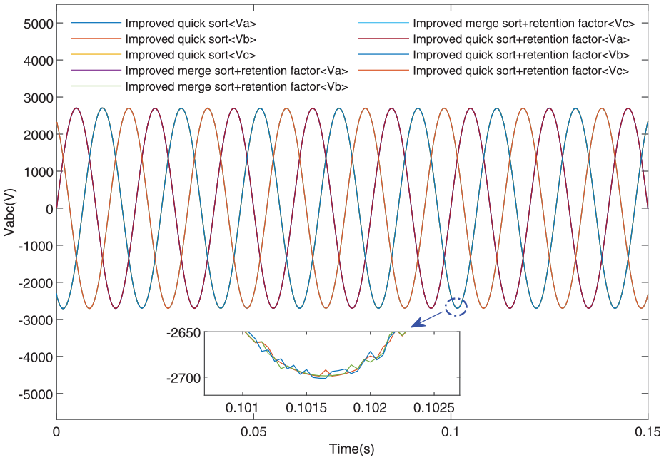
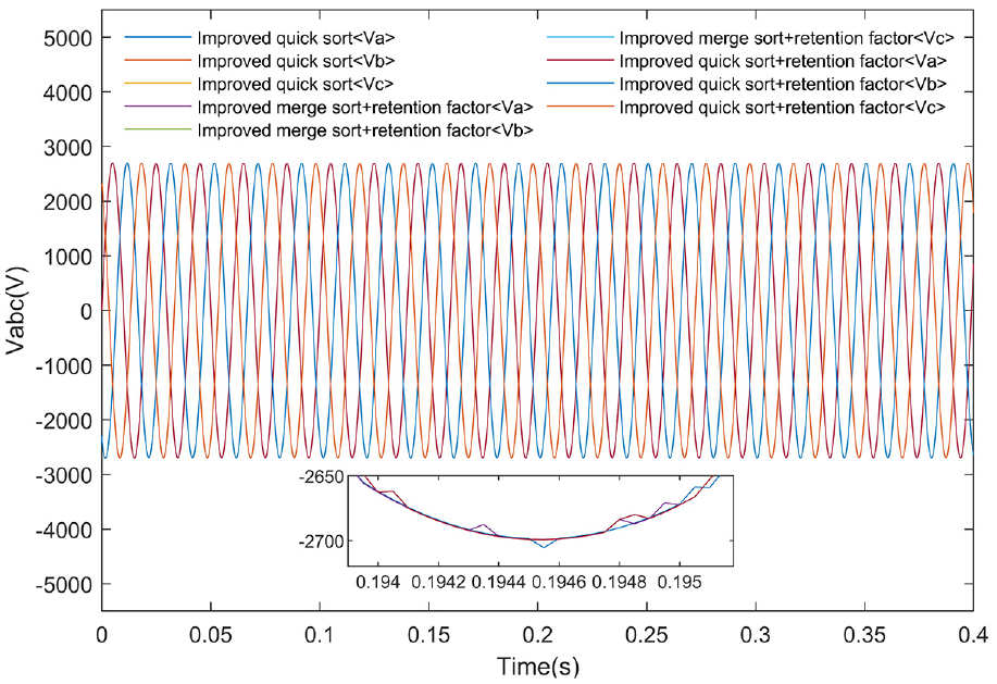
When the disturbance is not introduced into the power grid, the three-phase voltage of the MMC under improved quick sort, retention factor+improved merge sort, retention factor+improved quick sort control methods are obtained in Figure 13. Results show that the output three-phase voltage waveforms of the MMC under the three control methods are basically consistent. Actual output phase voltage amplitude of MMC is the same as 2.7 kV in Table 2, and the output waveform are smooth to meet the requirements of grid connection.
Three-phase voltages when using the three control methods.
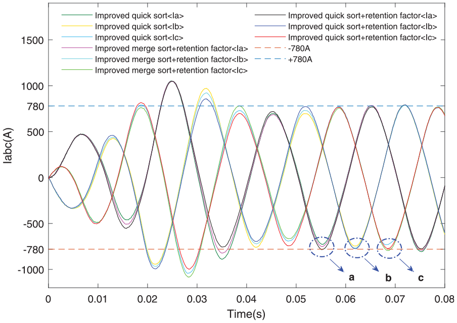
When the disturbance is not introduced into the power grid, the three-phase current of the MMC under improved quick sort, retention factor+improved merge sort, retention factor+improved quick sort control methods are obtained in Figure 14. Results indicate that the MMC converter output three-phase current under the three control methods all tends to stabilize after 0.06s, and the actual output phase current amplitude is stable at about 780 A, which is the same as the theoretical value calculated by equation (4). However, compared with the other two control methods, the retention factor+improved quick sort control strategy can enter the steady state earlier, and output a smoother current waveform.
Three-phase current when using the three control methods without disturbance.
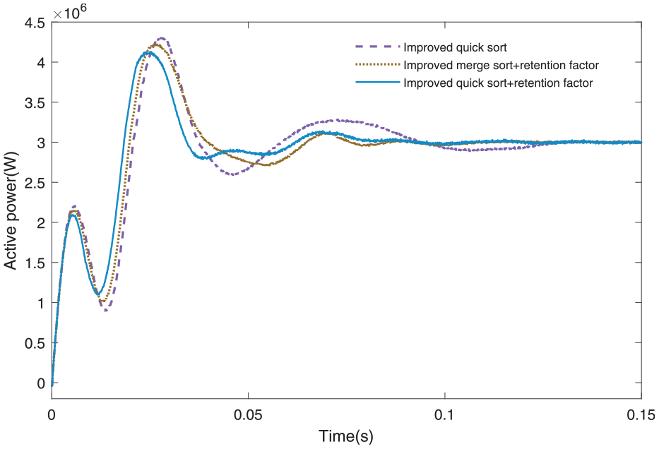
By analyzing Figures 15 and 16, it can be seen that MMC actual output active power and reactive power under three control methods all tends to stabilize after 0.12 s, and the active power and reactive power are stabilized at 3 and 1 MW, respectively. The three control methods all ensure the effective tracking of active and reactive power set in Table 2. However, compared with the other two control methods, the retention factor+improved quick sort control strategy can faster complete the dynamic regulation of active power and reactive power, which shows the correctness, effectiveness and rapidity of the proposed strategy.
Output active powers when using the three control methods without disturbance.
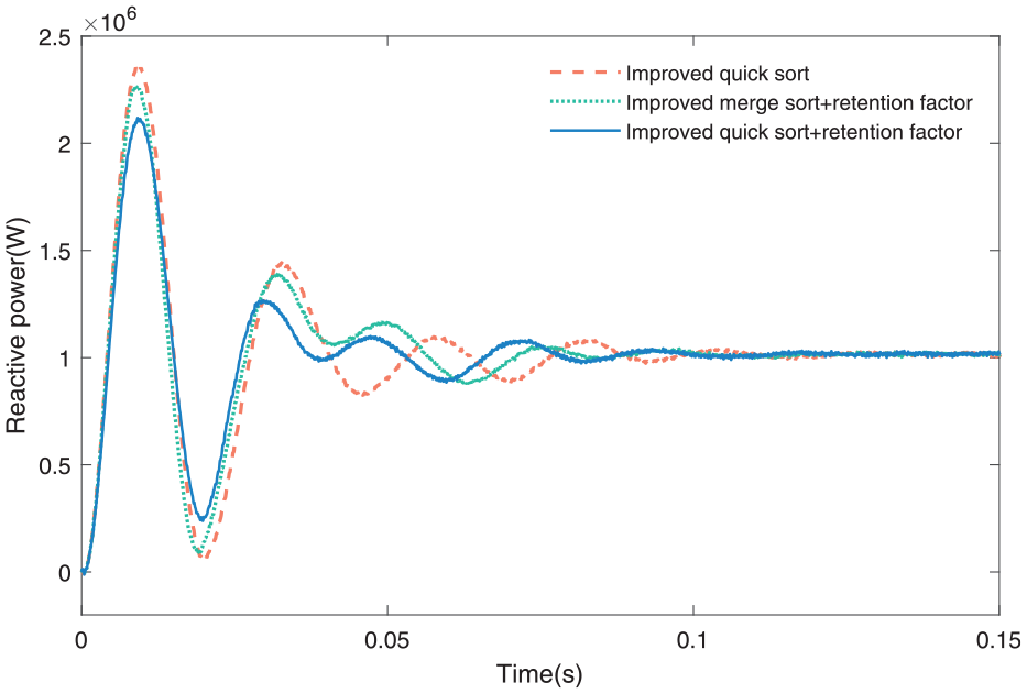
Output reactive powers when using the three control methods without disturbance.
Scenario of frequency fluctuation
Compared with the land power system, the capacity of ship power system is smaller, and the change of its operating load is easier to cause the fluctuation of power grid voltage and frequency, therefore, the ship power system generally has higher requirements for stability. 25 In order to further verify the robustness and rapidity of the strategy proposed in this paper, the power grid frequency fluctuation is increased by 0.5 Hz at 0.15 s and removed at 0.25 s.
Three-phase voltage when using three control methods during MMC frequency fluctuations is obtained in Figure 17, which shows that the MMC output three-phase voltage amplitude can be stabilized at 2.7 kV under the three control methods. According to Figure 18, the MMC output three-phase current under the three control methods all can be quickly self-regulated and without large drops after frequency abrupt changes, and the current quickly returns to the set value after the disturbance is removed.
Output three-phase voltage when using the three control methods under frequency fluctuations.

Output three-phase current when using the three control methods under frequency fluctuations.
The MMC output A-phase current waveform during the frequency fluctuation time period is obtained in Figure 19, which indicates that the MMC output phase-current amplitude eventually stabilizes at 647 A under the three control methods, but the retention factor+improved quick sort control strategy can make the system earlier enter the steady state and has better dynamic performance and regulation capability.
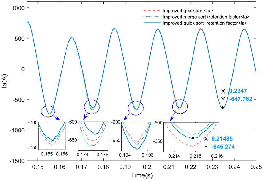
Output A-phase current when using the three control methods under frequency fluctuations.
Figures 20 and 21 receptively show the active power and reactive power waveforms output by the three control methods when the MMC frequency fluctuates. The conclusion can be drawn that the retention factor+improved quick sort control strategy has stronger regulation ability for disturbances and the shock amplitude is smoother, which can make the system more safe and reliable operation.

Output active power when using the three control methods under frequency fluctuations.
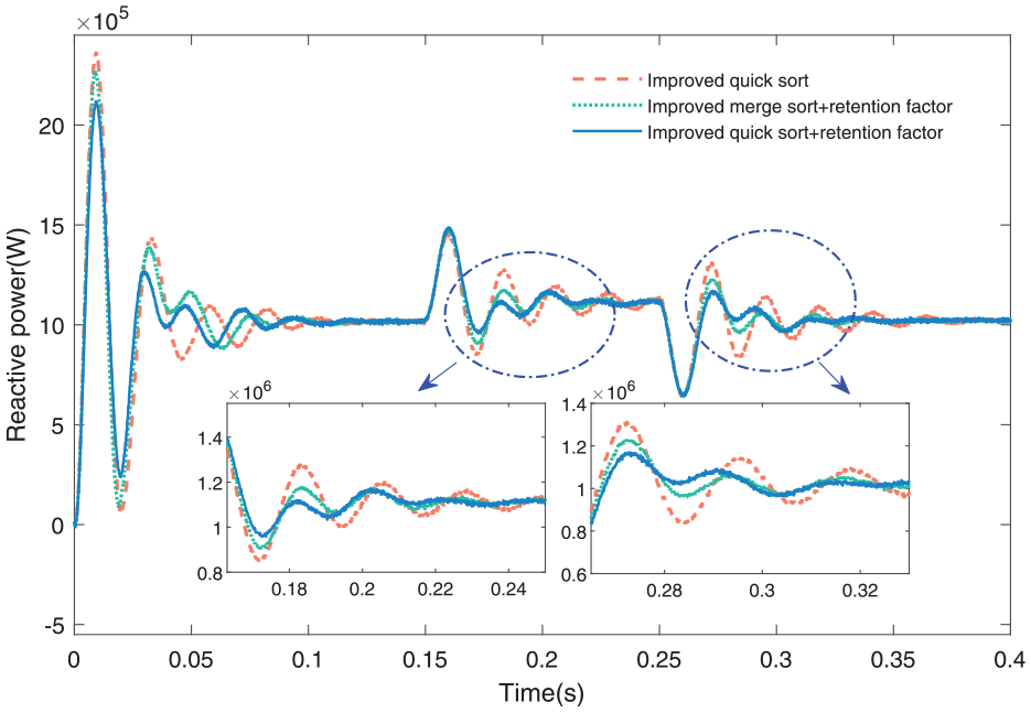
Output reactive power when using the three control methods under frequency fluctuations.
Scenario of voltage fluctuation
Any form of power grid voltage/frequency fluctuations will affect the grid-connected operation process of the PV system, 26 In order to further verify the robustness and rapidity of the strategy proposed in this paper, a certain the power grid voltage amplitude is dropped by 5% at 0.15 s and removed at 0.25 s.
The output active power and reactive power when using three control methods during MMC converter voltage fluctuations is obtained in Figures 22 and 23, which shows that the retention factor+improved quick sort control strategy significantly reduces the amplitude of oscillation, has better adjustment effect for disturbances, and makes the system has higher stability and safety.
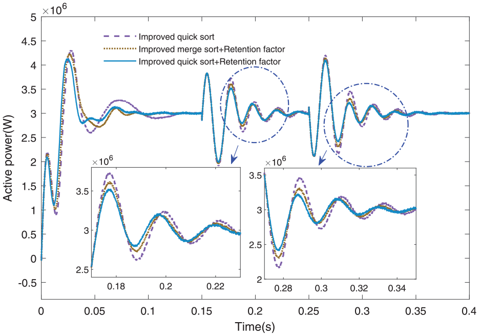
Output active power when using the three control methods under voltage fluctuations.
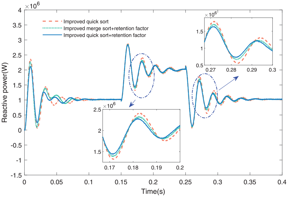
Output reactive power when using the three control methods under voltage fluctuations.
Conclusion
In this paper, a control strategy based on retention factor+improved quick sort is proposed to improve robustness and rapidity of the MMC sub-module capacitance voltage equalization control. A 31-level MMC model of large ships’ grid-connected photovoltaic power generation system is established for simulation verification and the following conclusions are drawn.
(1) Compared with bubble sort, quick sort, bidirectional bubble sort, and improved merge sort, the improved quick sort can sort arrays faster, and the more elements in the array, the more obvious the speed improvement, which verifies the efficiency of the improved quick sorting algorithm.
(2) After the retention factor method is introduced to the improved fast sort, the fluctuation of the sub-module capacitance voltage is still within the allowable range of the system, what’s more important the switching frequency of the sub-module capacitance is significantly reduced, which verifies the correctness and feasibility of the retention factor method.
(3) The proposed retention factor+improved quick sort has better control effect and regulation ability compared with improved quick sort and retention factor+improved merge sort in both normal operation and introduced disturbance conditions, and improves the dynamic performance and control accuracy of the system.
Footnotes
Declaration of conflicting interests
The author(s) declared no potential conflicts of interest with respect to the research, authorship, and/or publication of this article.
Funding
The author(s) disclosed receipt of the following financial support for the research, authorship, and/or publication of this article: The paper was supported by the education department of Jilin Province (Grant: JJKH20200044KJ), the Jilin Provincial development and reform Commission (Grant: 2022C045-11), Project of Beihua University (Grant: 201901012), Research and Innovation Project of Beihua University (Grant: [2023] 009).